

Allen-Bradley 836P-D1NMGA60PA-D4, 836P-D2NMGB20PP-D4, 836P-D1NFGA14PP-D4, 836P-D2NFGB50PP-D4, 836P-D1NFGB20PA-D4 Installation Manual
...
Installation Instructions
Original Instructions
Display Solid-state Pressure Switch with IO-Link
Catalog Numbers
836P-D1x, 836P-D2x, 836PF-D1x, 836PF-D2x
Summary of Changes
This publication contains new and updated information as indicated in the following table.
Topi c Page
Two new catalog numbers 1
New bullet under Safety Considerations regarding flush diaphragm 1
G 1/2 B Flush Diaphragm added to Process Connection table 3
G 1/2 B Flush Diaphragm dimensional drawing added to Process Connection dimensions 3
Added new bullet to beginning of Making the Mechanical Connection section 4
Safety Considerations
• Read this document for information on installation, handling, mounting, general product specifications, and operation of this product.
These installation instructions contain important information on handling the instrument.
• Working safety requires that all safety instructions and work instructions are observed.
• Observe the relevant local accident prevention regulations and general safety regulations for the range of use of the instrument.
• The installation instructions are part of the product and must be kept in the immediate vicinity of the instrument and readily accessible to
skilled personnel at any time.
• Skilled personnel must have carefully read and understood the operating instructions before any work begins.
• The Bulletin 836P-D is a pressure switch for measuring and monitoring absolute and gauge pressures. The device has been safely built with
state-of-the-art technology and meets the applicable requirements and EC directives. It can, however, be a source of danger if used
incorrectly or for anything other than the designated use.
• The Bulletin 836P-D has flush diaphragm for highly viscous or crystallizing media that can clog the bore of the process connection.
• Qualified individuals are required for installation and commissioning. Failure to comply results in personal injury or equipment damage.
• Before installation, commissioning and operation, be sure that the appropriate pressure switch has been selected in terms of range of
measurement, design, and specific conditions of measurement.
Qualified Personnel
Qualified personnel are understood to be personnel who, based on their technical training, knowledge of measurement and control technology, and
on their experience and knowledge of the country-specific regulations, current standards and directives, can implement the work that is described
and independently recognize potential hazards.
Recommended Installation for Optimal Performance
Gas Steam Liquid

Display Solid-state Pressure Switch with IO-Link
Specifications
c-UL-us, safety (for example, Electr.safety overpressure, …), USA, Canada
Certifications
Environment: Operating Conditions
Ambient Temperature Range -20…+80 °C (-4…+176 °F)
Media -20…_85 °C (-4…+185 °F)
Storage Temperature -20…+80 °C (-4…+176 °F)
Vibration Resistance 10 g (0.35 oz) (IEC 60068-2-6, under resonance)
Shock Resistance 50 g (1.76 oz) (IEC 60068-2-27, mechanical)
Humidity 45…75% RH
Ingress protection
Overpressure Limit 1.7 times for the relative pressure measuring ranges 16 psi, 1,000 psi, and 1,500 psi. Two times for the remaining available models.
Electrical
Power Supply 15…35 V DC
Current Consumpti on
Total Current Consumption With IO-Link: maximum 450 mA including switching current
Outputs
Output Type 2 x PNP, 1 PNP, and 4…20 mA analog
Zero Offset Adjustment Maximum 3% of span
Output Thresholds OUT 1 and OUT 2 are individually adjus table
Output Modes Selectable - Normally open, normally closed, window, hysteresis
Output Voltage (Power Supply -1V)
Output Current With IO-Link: OUT1 maximum 100 mA, OUT2 maximum 250 mA
Load Analog signal 4…20 mA: ≤ 0.5 kΩ
Service Life 100 million switching cycles
Time to Settle
Accurac y Data
Analog Signal
Non-linearity ≤ ±0.5% of span (BFSL, IEC 61298-2)
Long Term Drift ≤ ±0.2% of span (IEC 61298-2)
Switching Output Switch point accuracy: ≤ ±1% of span; Adjustment accuracy: ≤ ±0.5% of span
Display ≤ ±1.0% of span ± 1 digit
Temperature Error in Rate Temperature Range Typical: ≤ ±1.0% of span; Maximum: ≤ ±2.5 % of span
Temperature Coefficients in Rated Temperature Range Mean TC zero point: ≤ ±0.2% of span/10 K (typical); Mean TC span: ≤ ±0.1% of span/10 K (typical)
Reference Operation Conditions
Operating Temperature 15…25 °C (59…77 °F)
Atmospheric Pressure 950…1,050 mbar (13.78…15.23 psi)
Humidity 45…75% r. h.
Nominal Position Process connection lower mount (LM)
Electrical S afety
Short-circuit Protection 4…20 mA, Out 1/Out 2 vs. V-
Reverse Polarity Protection V+ vs. V-
Insulation Voltage 500V DC
Overvoltage Protection 40V DC
CE conformity - Pressure equipment directive 97/23/EC
EMC Directive 2004/108/EC/,EN 61326 emission (group 1 , class B), and interference immunity (industrial application)
RoHs conformity - 2011/65/EU
IP65 and IP67. The stated ingress protection (per IEC 60529) only applies when plugged in using mating connectors that have the
appropriate ingress protection.
Switching outputs with :
Analog signal 4…20 mA; 70 mA;
Without analog signal: 45 mA
Analog Signal: 3 ms
Switching Output: 20 ms with IO-Link
≤ ±1.0% of span
Including non-linearity, hysteresis, zero offset, and end value deviation (corresponds to measured error per
IEC 61298-2). Calibrated in vertical mounting position with process connection facing downwards.
2 Rockwell Automation Publication 836P-IN001B-EN-P - December 2017

Specifications (Continued)
38
(1.5) dia.
36
(1.42)
72
(2.83)
92.3
(3.63)
45
(1.77)
35
(1.38) dia.
27
(1.06)
20
(0.79)
14
(0.55)
1/4 in. NPT
25 (0.98) ± 0.1 dia.
29.5 (1.16) dia.
M12x1
5 plg./5-pole
29.5
(1.16)
Weight approximately 220 g (7.76 oz)
OUT1
4…20 mA
15…35V DC
(+)
(-)
14
23
OUT1
OUT2
15…35V DC
(+)
(-)
14
23
1 PNP x 4…20 mA
2 PNP
Material
Wette d Par ts
Process Connection Stainle ss Steel 316 L
Pressure Sensing Elements
Non-wetted Par ts
Housing Stainless Steel 304
Keyboard TPE-E
Display Window Polycarbonate
Display Head Polycarbonate and ABS
Process Connection
Thread
< 9.8 bar (142 psi): Stainless Steel 316 L
≥ 9.8 bar (42 psi): Stainless Steel 13- 8 PH
1/4 in. NPT Male
1/4 in. NPT Female
G 1/4 in. BSPP Male
G 1/4 in. BSPP Female
G 1/2 in. B Blush
Display Solid-state Pressure Switch w ith IO-Link
IO-Link Specifications
IO-Link Protocol:
Minimum Cycle Time:
Rate:
Process Data Length:
Data Storage Support:
Vers ion 1 .1
3 ms
COM2 (38.4 k Baud)
16 bit (Frame 2.2)
Yes
1/4 in. NPT Female Dimensions [mm (in.)]
Wiring Diagrams
IMPORTANT IO-Link operation is only available when connected to an IO-
Link Master such as the 1734-4IOL or any competitive IO-Link
Master. While in Standard IO mode (SIO), the sensor operates as
a discrete PNP output.
Mating Cables
Catalog Number 889D – F4AC-2 (M12x1 connector)
Catalog Number 889D-R4AC-2 (M12x1 right angle connector)
Process Connection
Attribute Description
Measuring Cell Piezoresistive measuring cell and metallic measuring diaphragm
Application Measurement and monitoring of absolute and gauge pressures
Rockwell Automation Publication 836P-IN001B-EN-P - December 2017 3
Process Connection
Thread
− 1/4 in. NPT female
− 1/4 in. NPT male
− G 1/4 in. BSPP female
− G 1/4 in. BSPP male
− G 1/2 in. B Flush Diaphragm

Display Solid-state Pressure Switch with IO-Link
G
L1
G
L1
D1
L3
L2
L1
G
Process Connection [mm (in.)] (Continued)
G 1/4 in. BSPP Male 1/4 in. NPT Male G 1/4 in. BSPP Female G 1/2 in. B Flush Diaphragm
L1
L2
L3
G
D1
G L1 G L1 G L1 L2 L3 D1 G L1 L2 L3 D1
G 1/4 13 (0.51) 1/4 in. NPT 13 (0.51) G 1/4 in. 20 (0.79) 13 (0.51) 10 (0.39) 25 (0.98) G 1/2 in. B 23 (0.91) 20.5 (0.81) 10 (0.39) Ø 18 (0.71)
Range of Measurement [bar (psi)]
Switch
Gauge Pressure -1…+20 (-14.5…+300) 0…551 (0…8000)
Absolute Pressure/Vacuum -1…+20 (-14.5…+300) 0…20 (0…300)
836P-D1
836PF-D1
836P-D2
836PF-D2
IMPORTANT Overpressure Limit 2 times; 1.7 times for the relative pressure
measuring ranges 160 psi, 1000 psi, and 1500 psi.
Output Signals
Output Model Type Switching Output 1 Switching Output 2 Analog Signal
1 PNP x 4…20 mA PNP — 4…20 mA (3 wi re)
2 PNP PNP PNP —
Commissioning
ATT EN TI ON : Only for use with the pressure switch if it is in perfect condition for safety.
Check the following points before commissioning:
• Fluid leakage is indicative of damage.
• Since this product is a safety-relevant component, check the diaphragm for any visible damage.
Required tool: Wrench size 27 open-ended wrench and screwdriver.
Making the Mechanical Connection
• For the flush mount connection option, do not remove the protective cap until shortly before mounting. During installation, confirm that
the diaphragm is not damaged.
• While mounting, make sure that the sealing faces at the instrument are clean and undamaged.
• Only screw in or unscrew the instrument via the wrench. Never use the case as a working surface.
• The correct torque depends on the dimensions of the process connection and the gasket used (form/material).
• When screwing in, be careful not to cross the threads.
4 Rockwell Automation Publication 836P-IN001B-EN-P - December 2017

Display Solid-state Pressure Switch w ith IO-Link
per EN 837 per DIN 3852-E
NPT
Types of Sealing
Figure 1 - Parallel Thread Tapered Thread (NPT)
Correct sealing of the process connections with parallel threads at the sealing face must be made using suitable flat gaskets and sealing rings.
The sealing of the tapered threads (for example, NPT thread) is made by providing the thread with additional sealing material such as, PTFE tape
(EN 837-2).
Making the Electrical Connection
• The instrument must be grounded via the process connection.
• The power supply for the pressure switch must be made via an energy-limited electrical circuit in accordance with section 9.3 of
UL/EN/IEC 61010-1 or an LPS to UL/EN/IEC 60950-1 or class 2 in accordance with UL1310/UL1585 (NEC or CEC). The power
supply must be suitable for operation above 2000 m (6561.6 ft) in case the pressure switch be used at this altitude.
• For cable outlets, make sure that no moisture enters at the cable end.
Disconnect and Disposal
ATT EN TI ON : Residual media in the dismounted pressure transmitter can result in a risk to persons, the environment, and equipment. Take sufficient
precautionary measures.
Disconnect: Only disconnect the pressure transmitter once the system has been depressurized.
Disposal: Incorrect disposal can put the environment at risk.
Dispose of instrument and packaging materials in an environmentally compatible way and in accordance with the country-specific waste disposal
regulations.
Rockwell Automation Publication 836P-IN001B-EN-P - December 2017 5

Display Solid-state Pressure Switch with IO-Link
Status switching output2 (optional)
Status switching output1
Display mode
•Short press
Display of the unit
• Long press
Display of the set parameters
Programming mode
•Short press
Menu up
Parameter value up (step-wise)
• Long press
Menu up
Parameter value up (fast)
Display mode
•Short press
Display of the unit
• Long press
Enter the programming mode
Programming mode
•Short press
Menu up
Parameter value up (step-wi se)
• Long press
Menu down
Param eter valu e down (f ast)
Display mode
•Short press
Display of the unit
Four-digit LED display
•Display pressure value
• Display menu item
•Display parameter
Programming mode
•Short press
Select menu item
Confirmation of the input
Note: The pressure switch has two operating
modes, the display mode and the programming
mode. The function of the keys depends on the
selected operating mode.
Enter key: In programming mode, press the
enter key once to set the values for the selected
parameters.
Note: Short press equals three seconds; long press equals five seconds.
Programming
Figure 2 - Keys and Functions
Keys (Simultaneously press the Info and Menu
Keys to Exit the Programming Mode and return
to Display Mode.)
Function
Display Mode Programming Mode (Press the Menu Key for five seconds to enter Programming Mode.)
Short Press:
Display of the unit
Long Pres s:
Display of set parameters
Short Press:
Display of the unit
Long Pres s:
Enters programming mode
Short press: toggle paramete r up (step-wise) Shor t press: toggle parameter up (fast scroll)
Short press: toggle parameter dow n
(step-wise)
Table 3 - Parameters
Parame ter Descri ption Parame ter Descr iption
SP1/SP2 Hysteresis function: Switch point switching output (1 or 2) UNIT Unit switching
FH1/FH2 Window function: Window high switching output (1 or 2) 0SET Of fset adjustment (3% of span)
RP1/RP2 Hysteresis function: reset point switching output (1 or 2)
FL1/FL2 Window function: Window low switch output (1 or 2)
EF Extended programming functions
RES Re turn the set parameter to the factory settings
DS1/DS2
DR1/DR2
OU1 Switching function switching output (1 or 2)
OU2
Switch delay time, which must occur without interruption before any electrical signal change
occurs (SP1 or SP2)
Switch delay time, which must occur without interruption before any electrical signal change
occurs (RP1 or RP2)
HNO = hysteresis function, normally open
HNC = hysteresis function, normally closed
FNO = window function, normally open
FNC = window function, normally closed
Display value in display mode
DISM
DISU Display update 1,2,5,10 updates/second
DISR Rotate display indicator by 180°
RHL Clear the minimum- and maximum - value memories
PAS
TAG Input of a 16-figure alphanumeric measuring point number
CT= actual pressure value; LOW, HIGH = minimum, maximum pressure value OFF= display
off;
SP1/FH1 = function switch po int 1, RP1/FL1 = function reset point 1,
SP2/FH2= function switch point 2, RP2/FL2 = function reset point 2
Password input, 0000= no password
Password input digit by digit
Long press: toggle parameter down (fast scroll)
6 Rockwell Automation Publication 836P-IN001B-EN-P - December 2017
Display Solid-state Pressure Switch w ith IO-Link
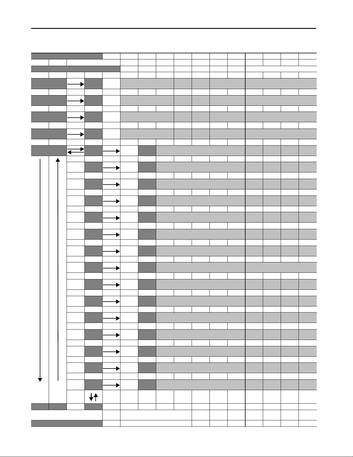
Menu (Programming and Factory Setting)
Display Mode
▼▲ Press menu key for 5 se conds
Programming Mode (to set values, press enter) Factory setting:
▼▲ Enter
SP1/FH1 Valu e (Minimum: MBA +0.5% Maximum: MBE) Instrument nominal pressure
▼▲ Enter
RP1/FL1 Val ue (Minimum: MBA Maximum: SP1 -0.5%) Instrument nominal pressure -10%
▼? ▲ Enter
SP2/FH2 Valu e (Minimum: MBA +0.5% Maximum: MBE) Instrument nominal pressure
▼? ▲ Enter
RP2/FL2 Val ue (Minimum: MBA Maximum: SP2-0.5%) Instrument nominal pressure -10%
▼? ▲ Enter Enter
EF RES Yes /N o Reset to factory setting
▼ ▲ Enter
DS1 Valu e 0…50 s 0 s
▼ ▲? Enter
DR1 Value 0…50 s 0 s
? ▼ ▲? Enter
DS2 Valu e 0… 50 s 0 s
? ▼ ▲? Enter
DR2 Value 0… 50 s 0 s
? ▼ ▲? Enter
OU1 PAR A HNO,HNC,FNO,FNC HNO
? ▼ ▲? Enter
OU2 PAR A HNO,HNC,FNO,FNC HNO
? ▼ ▲? Enter
UNIT Unit BAR,MPA,KPA,PSI,KG/cm2 Order-related
? ▼ ▲? Enter
0SET Yes /N o Zero point adjustment 3% of span
? ▼ ▲? Enter
DISM PAR A ACT, HIGH, LOW,OFF,SP1/FH1,RP1/FL1,SP2/FH2,RP2/FL2 ACT
? ▼ ▲? Enter
DISU Val ue 1/2/5/10 update/second 5
? ▼ ▲? Enter
DISR Yes / No Rotate display by 180°
? ▼ ▲? Enter
RHL Yes/ No Reset HIGH, LOW
? ▼ ▲? Enter
PAS Valu e Password without
? ▼ ▲? Enter
TAG Va lue Measuring point number without
END END Legend:
Press the enter key to return to display mode an d exit
programming mode.
Display Mode MBE = End of measuring range
Rockwell Automation Publication 836P-IN001B-EN-P - December 2017 7
MBA = Start of measuring range

Rockwell Otomasyon Ticaret A.Ş., Kar Plaza İş Merkezi E Blok Kat:6 34752 İçerenköy, İstanbul, Tel: +90 (216) 5698400
Rockwell Automation Support
Use the following resources to access support information.
Documentation Feedback
Your comments will help us serve your documentation needs better. If you have any suggestions on how to improve this document, complete the
How Are We Doing? form at http://literature.rockwellautomation.com/idc/groups/literature/documents/du/ra-du002_-en-e.pdf.
Technical Support Center
Knowledgebase Articles, How-to Videos, FAQs, Chat, User
Forums, and Product Notification Updates.
https://rockwellautomation.custhelp.com/
Local Technical Support Phone Numbers Locate the phone number for your country. http://www.rockwellautomation.com/global/support/get-support-now.page
Direct Dial Codes
Find the Direct Dial Code for your product. Use the code to
route your call directly to a technical support engineer.
http://www.rockwellautomation.com/global/support/direct-dial.page
Literature Library
Installation Instructions, Manuals, Brochures, and
Technical Data.
http://www.rockwellautomation.com/global/literature-library/overview.page
Product Compatibility and Download
Center (PCDC)
Get help determining how products interact, check
features and capabilities, and find associated firmware.
http://www.rockwellautomation.com/global/support/pcdc.page
Waste Electrical and Electronic Equipment (WEEE)
At the end of life, this equipment can be collected separately from
any unsorted municipal waste.
Rockwell Automation maintains current product environmental information on its website at
http://www.rockwellautomation.com/rockwellautomation/about-us/sustainability-ethics/product-environmental-compliance.page
.
Allen-Bradley, Rockwell Automation, and Rockwell Software are trademarks of Rockwell Automation, Inc.
Trademarks not belonging to Rockwell Automation are property of their respective companies.
Publication 836P-IN001B-EN-P - December 2017 14142257.01
Supersedes Publication 836P-IN001A-EN-P - January 2016 10002065887 Ver 01
Copyright © 2017 Rockwell Automation, Inc. All rights reserved. Printed in the U.S.A.
 Loading...