

Installation Instructions
Original Instructions
Plug-in Limit Switch Installation and Operating Instructions
Catalog Numbers
802T
ATT ENT IO N: To avoid electrical shock and unintended operation of
equipment, disconnect all power to the limit switch and the controlled
equipment before proceeding with any repair or adjustment of the limit
switch.
Overview
Position the conduit entering the switch such that any fluid inside the conduit will
not drain into the switch enclosure. Apply sealing compound to conduit threads
to prevent against entrance of fluids through the threads.
The base may be mounted by either of two methods:
1. Two #10–32 tapped holes are provided for rear mounting.
IMPORTANT Make sure the screws used for rear mounting are not so long
as to interfere with the screws used to secure the front to the
base.
2. Two clearance holes for #10 screws are provided for front
mounting.
Wiring
IMPORTANT The contacts in each switching element must have the same
The pressure type connector terminals in the base will accept No. 12AWG and
smaller solid or stranded wire. For proper tightening , it is sugge sted that nothing
smaller than No. 18 AWG be used. B efore inserting wire under the pressure
plates, strip the insulation approximately 3/8 inch. Tighten all pressure plate
terminals whether used or not, to avoid interference with the switch cover.
A grounding screw is located in the terminal base enclosure near the conduit
opening. If the grounding screw has a self lifting pressure pla te and a wire barrier,
the proper installed position of the ground wire is between the pressure plate
and the wire barrier in a direction parallel to the edge of the casting. Be sure the
ground w ire does not interfere with the gasket or wi th the switch p ortion of the
device.
After wiring has b een completed, che ck that all wires are in the wiring cavity of
the terminal block so they will not interfere with the switch when it is plugged
into the terminal block. Recheck all wiring terminal screws for tightness.
IMPORTANT For switches which have been factory wired, check wire color
polarity. The circuit diagram is shown on the nameplate.
and their position in the terminal block for proper circuit hookup.
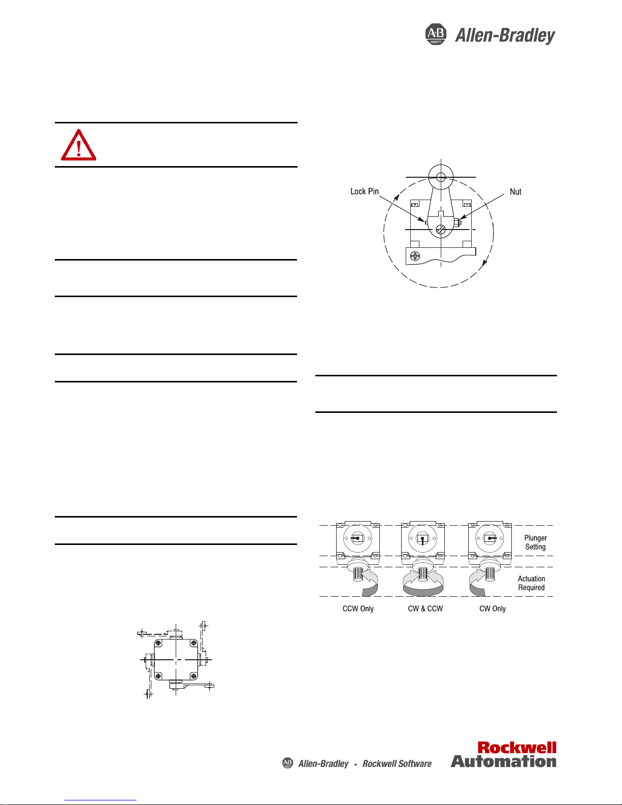
Lever Positioning
The lever on rotary actuated devices is adjustable to any position through 360°
around the shaft. Loosen the nut, move
securely re-tighten the nut (see Figure 2).
the lever to the desired position and
Figure 2
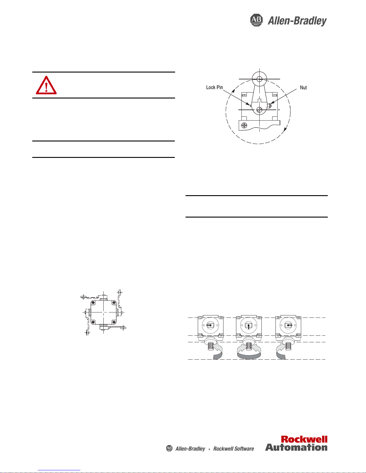
Changing Direction of Actuation
The switch action of most lever operated limit switches may be adjusted to
operate with either a clockwise, a counterclockwise, or both direction movement
of the shaft. The maintained and neutral position style of devices op erate in
both directions and cannot be changed.
To change the actuation direction, follow the steps below:
IMPORTANT This procedure must be performed in a clean environment to
Step 1: Loosen the four head mounting screws and remove the operating head
from the switch body.
Step 2: Locate the plunger on the underside of the operating head.
Step 3: Pull the plunger outward and rotate it in steps of 90° to provide the
operating mode desired. The respective settings are shown in the Figure 3.
Step 4: Make sure the plunger is pushed back inward and the “O” ring is
properly seated before the operating head is reattached to the switch body.
Step 5: Securely re-tighten (approximately 1.35…2.03 N•m (12…18 lb•in) the
operating head mounting screws.
Step 6: Check for the desired actuation mode.
avoid the introduction of foreign material into the operating
mechanism.
When the switch has been plugged into the terminal block, securely tighten the
two cover screws to compress the body gasket.
Actuator Head Positioning
The actuator head may be placed in any of four positions on the switch body.
Loosen the four captive screws. Place the head in the desired position and
securely re-tighten the four screws (see Figure 1).
Figure 1
Figure 3
Renewal Parts
If renewal parts or additional lubricant is required, give the bulletin number,
catalog number, and series letter found on the nameplate.
Installation Instructions
Antihorologique
Uniquement
Horologique et
Antihorologique
Horologique
Uniquement
Position du
plongeur
Fonctionnement
desire
Original Instructions
des Interrupteurs de Position Enfichables du Bulletin 802T
Catalog Numbers
802T
ATT ENT IO N: Toujours couper toutes sources d’alimentation à l’interrupteur
et l’appareil sous commande avant de faire l’entretien ou le rêglage sur
l’interrupteur. Ceci êvitera les chocs êlectriques ou une opêration inattendue
de l’appareil sous commande.
MONTAGE
Le conduit doit être placé de façon à éviter l’entrée des liquides dans
l’interrupteur. Sceller aussi les filets du conduit.
1. Montage par l’arrière – Deux trous filetés à No. 10-32 sont fournis
IMPORTANT Choisir les vis d’une longueur compatible aux vis d’avant,
2. Montage par l’avant – Deux trous de débourrage (vis No. 10) sont
fournis.
pour éviter l’interférence.
CÀBLAGE
Polarité— Les contacts doivent être branchés à la même polarité. Voir le schéma
des connexions sur la plaque signalétique.
Bornes de Connexion à Pression — La gamme des fils à employer est de 18 AWG
jusqu’a 12 AWG.
Dénuder les fils 3/8.
Serrer toutes les vis pour éviter l’interférence avec le couv- ercle de l’interruptuer.
Une vis de mise à la terre est fournie dans le boitier.
S’sssurer qu’il n’existe pas d’interférence entre les fils et l’interrupteur avant de
l’enficher.
Bien serrer les deux vis du couvercle pour comprimer le joint d’étanchéité.
Interrupteurs Câblés à L’usine — S’assurer de la bonne disposition des
branchements ainsi que de la position des fils sur les bornes.
LA TÊTE DE COMMANDE
On peut installer la tête de commande en quatre oreintations. Pour changer les
positions, désserrer les vis, pivoter la tête de commande, resserrer les quatre vis.
(Ill. 1)
Ill. 2
Changing Direction of Actuation
La plupart des interrupteurs de position sont réglables pour éllecluer un
fonctionnement on sons horologique sons anti-horologique ou dans les deux
directions.
Les interrupteurs maintenus et à position neutre ne sont pas changeables ils
fonctionnement dans deux directions seulement.
IMPORTANT Toujours régler ces interrupteurs dans les conditions
1. Desserrez les quatre vis de montage de la tête et enle- vez la tête
d’opération du corps de l’interrupteur.
2. Localisez le plongeur en-dessous de la tête d’opération.
3. Tirez le plongeur vers l’ extérieur et tournez le avec un pas de 90
afin d’obtenir le mode désiré. Voir reglages respectif en Ill. 3.
4. Faites sûr le plongeur est repoussé dans l’ intérieur et que le joint est
proprement placé avant la tête d’opération est réattaché au corps de
l’interrupteur.
5. Reserrez (approximativement 1,36 Nm – 2.03 nm) les vis de
montage de la tête.
6. Vérifiez le mode d’action désiré.
environnantes propres pour éviter l’entrée des saletés dans le
mécanisme.
Ill. 1
LEVIERS (Type à levier seulement)
Les leviers sont ajustables dans un champ de mouvement de 360°. Déserrer la
cheville de sécurité, bouger le levier jusqu’ à la position requise er serrer l’écrou,
(voir Ill.2).
Figure 3
PIÉCES DE RECHANGE OU LUBRIFIANT ADDITIONNEL
Votre commande doit inclure le numéra de catalogue et la lettre de série.

Notes:
Plug-in Limit Switch Installation and Operating Instructions
Rockwell Automation Publication 802T-IN007A-MU-P - July 1993 3

Rockwell Otomasyon Ticaret A.Ş., Kar Plaza İş Merkezi E Blok Kat:6 34752 İçerenköy, İstanbul, Tel: +90 (216) 5698400
Notes:
Rockwell Automation maintains current product environmental information on its website at
http://www.rockwellautomation.com/rockwellautomation/about-us/sustainability-ethics/product-environmental-compliance.page
Allen-Bradley, Rockwell Automation, and Rockwell Software are trademarks of Rockwell Automation, Inc. Trademarks not belonging to Rockwell Automation are property of their respective companies.
.
Publication 802T-IN007A-MU-P - July 1993 40146–752–02 Ver 01
Copyright © 1993 Rockwell Automation, Inc. All rights reserved. Printed in the U.S.A.
 Loading...