

Page 1
SERVICE MANUAL
For XONE:62 VERSION 1 and VERSION 2
Publication AP3842
Page 2
Allen & Heath Technical Support
This service manual provides technical information for servicing the XONE:62. It refers to
both the original (VERSION 1) and the revised (VERSION 2) model XONE:62. Whilst we
believe the information presented to be reliable we do not assume responsibility for
inaccuracies. We also reserve the right to make changes in the interest of further product
development.
For further technical support please contact us at Allen & Heath. The contact details are
printed below. To help us provide the most efficient service please quote the console
serial number in any communication regarding this product. Our Internet site provides
further information on our full product range as well as contact details for our distribution
network.
This product complies with the European Electromagnetic
Compatibility directives 89/336/EEC & 92/31/EEC and the
European Low Voltage Directives 73/23/EEC &
93/68/EEC.
This product has been tested to EN55103 Parts 1 & 2 1996 for use in
Environments E1, E2, E3, and E4 to demonstrate compliance with the
protection requirements in the European EMC directive 89/336/EEC.
During some tests the specified performance figures of the product
were affected. This is considered permissible and the product has
been passed as acceptable for its intended use. Allen & Heath has a
strict policy of ensuring all products are tested to the latest safety and
EMC standards. Customers requiring more information about EMC
and safety issues can contact Allen & Heath.
NOTE: Any changes or modifications to the console not approved by
Allen & Heath could void the compliance of the console and therefore
the users authority to operate it.
XONE:62 Service Manual AP3842 Issue 3
Copyright © 2004 Allen & Heath. All rights reserved
Kernick Industrial Estate, Penryn, Cornwall, TR10 9LU, UK
Web: http://www.allen-heath.com
Email: sales@allen-heath.com
support@allen-heath.com
spares@allen-heath.com
2 XONE:62 Service Manual
Page 3
Important Safety Instructions
WARNINGS - Read the following before proceeding :
CAUTION
ATTENTION: RISQUE DE CHOC ELECTRIQUE – NE PAS OUVRIR
Read instructions: Retain these safety and operating instructions for future reference.
Adhere to all warnings printed here and on the console.
Do not remove covers: Operate the console with its covers correctly fitted. Disconnect mains
power by unplugging the power cord if the covers need to be removed
for setting internal options. This work should be carried out by
competent technical personnel only.
Power sources: Connect the console to a mains power only of the type described in
the User Guide and marked on the rear panel. Use the power cord
with sealed mains plug appropriate for your local mains supply as
provided with the console. If the provided plug does not fit into your
outlet consult your service agent for assistance.
Power cord routing: Route the power cord so that it is not likely to be walked on, stretched
or pinched by items placed upon or against it.
Grounding: Do not defeat the grounding and polarisation means of the power cord
plug. Do not remove or tamper with the ground connection in the
power cord.
WARNING: This equipment must be earthed.
Water and moisture: To reduce the risk of fire or electric shock do not expose the console
to rain or moisture or use it in damp or wet conditions. Do not place
containers of liquids on it which might spill into any openings.
Ventilation: Do not obstruct the ventilation slots or position the console where the
air flow required for ventilation is impeded. If the console is to be
operated in a rack unit or flightcase ensure that it is constructed to
allow adequate ventilation.
Heat and vibration: Do not locate the console in a place subject to excessive heat or
direct sunlight as this could be a fire hazard. Locate the console away
from any equipment which produces heat or causes excessive
vibration.
Servicing: Switch off the equipment and unplug the power cord immediately if it
is exposed to moisture, spilled liquid, objects fallen into the openings,
the power cord or plug become damaged, during lightening storms, or
if smoke, odour or noise is noticed.
Installation: Install the console in accordance with the instructions printed in the
User Guide. Do not connect the output of power amplifiers directly to
the console. Use audio connectors and plugs only for their intended
purpose.
XONE:62 Service Manual 3
Page 4
Important Mains plug wiring instructions.
The console is supplied with a moulded mains plug fitted to the AC
mains power lead. Follow the instructions below if the mains plug has
to be replaced.
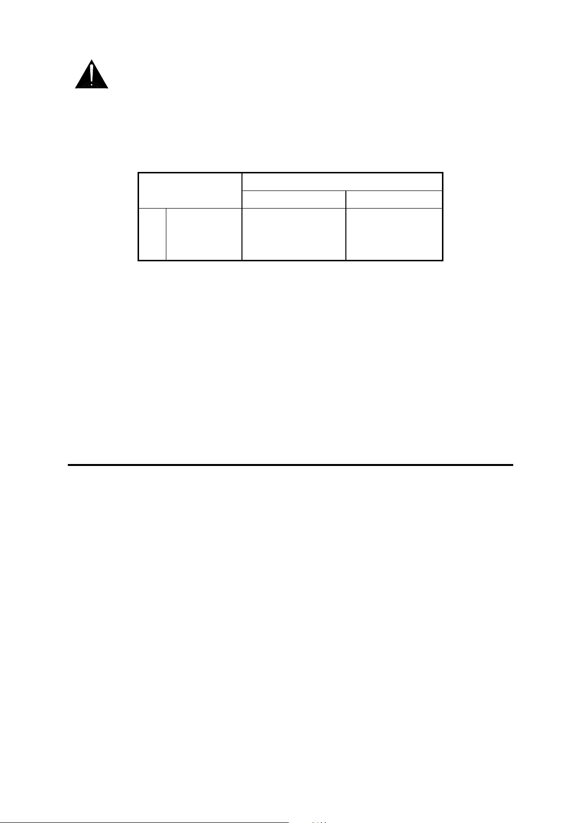
The wires in the mains lead are coloured in accordance with the
following code:
TERMINAL
L
N
E
The wire which is coloured Green and Yellow must be connected to
the terminal in the plug which is marked with the letter E or with the
Earth symbol. This appliance must be earthed.
The wire which is coloured Blue must be connected to the terminal in
the plug which is marked with the letter N.
The wire which is coloured Brown must be connected to the terminal
in the plug which is marked with the letter L.
Ensure that these colour codes are followed carefully in the event of
the plug being changed.
Precautions
WIRE COLOUR
European USA/Canada
LIVE BROWN BLACK
NEUTRAL BLUE WHITE
EARTH GND GREEN & YELLOW GREEN
Damage : To prevent damage to the controls and cosmetics avoid placing heavy
objects on the control surface, scratching the surface with sharp
objects, or rough handling and vibration.
Environment : Protect from excessive dirt, dust, heat and vibration when operating,
servicing and storing. Avoid tobacco ash, smoke, drinks spillage, and
exposure to rain and moisture. If the console becomes wet, switch off
and remove mains power immediately. Allow to dry out thoroughly
before using again.
Cleaning : Avoid the use of chemicals, abrasives or solvents. The control panel is
best cleaned with a soft brush and dry lint-free cloth. The faders,
switches and potentiometers are lubricated for life. The use of
electrical lubricants on these parts is not recommended.
Transporting : The console may be transported as a free-standing unit or mounted in
a rack or flightcase. Ensure that the connector pod is secured in place
with the locking screws fitted to prevent movement. Protect the
controls from damage during transit. The faders are best positioned at
the top of their travel if the console is transported without a suitable
flightcase, rack or carton. Use adequate packing if you need to ship
the unit.
4 XONE:62 Service Manual
Page 5

Contents
Important Safety Instructions ................ 3
Mains Plug Wiring Instructions ............. 4
Precautions ........................................... 4
Welcome to the XONE:62 ..................... 6
VERSION 1 and VERSION 2 ................. 7
Order Codes.......................................... 7
Panel Drawings VERSION 1 ................. 8
Panel Drawings VERSION 2 ................. 9
Cue Sheet VERSION 1 ........................ 10
Cue Sheet VERSION 2 ........................ 11
Specifications ...................................... 12
Optional Rack Ears ............................. 14
Connecting Mains Power.................... 15
Block Diagram VERSION 1 ................ D1
Block Diagram VERSION 2 ................ D2
INPUT PCB ......................................... D3
INPUT 1-2 Circuit ................................ D4
INPUT 3-6 Circuit ................................ D5
LEFT PCB ........................................... D6
LEFT Circuit ........................................ D7
RIGHT PCB ......................................... D8
RIGHT Circuit...................................... D9
ROTARY OUTPUT ............................ D10
CROSSFADE PCB............................ D11
CROSSFADE Circuit Sheet 1 ........... D12
CROSSFADE Circuit Sheet 2 ........... D13
Earthing ............................................... 15
Plugging up the System...................... 16
Cable Wiring........................................ 17
Replacing the Crossfader ................... 18
Tips and Troubleshooting ................... 19
Gain and Operating Levels ................. 20
CONNECTOR PCB........................... D14
CONNECTOR Circuit........................ D15
PSU PCB and Circuit VERSION 2 .... D16
MAINS PCB and Circuit VERSION 2 D17
PSU PCB VERSION 1....................... D18
PSU Circuit VERSION 1.................... D19
XONE:62 Service Manual 5
Page 6

Welcome to the XONE:62
From the User Guide:
The Allen & Heath XONE:62 presents a unique combination of performance tools for the
professional DJ in a stylish and solidly built club format. Above all, it features sound
quality second to none. XONE:62 has been designed and constructed using the same
rigorous standards we apply to our large format professional consoles used and
respected by top engineers throughout the world.
XONE:62 provides 6 dual stereo channels, with A and B inputs on each, two offering
mic inputs, adding up to a massive 10 stereo and 2 microphone inputs. A full range of
connectors means that you can connect up to 4 turntables, 2 mics, CD players, MD
players, drum machines, samplers, and pretty much anything else you might want to
bring into the mix.
The more bands of EQ you have, the more creative you can get with your mix. That is
why we give you 4 EQ controls rather than the usual 3. Each band has a safe +6dB
boost and a massive –26dB of cut, enough to creatively shape your sound well beyond
normal EQ range, and without overloading your system. Punch the effect in or out using
the EQ on switch.
Channels 3 to 6 can be assigned to either side of the high spec Penny & Giles VCA
crossfader. This controls the audio using a DC voltage meaning that it can take a huge
amount of punishment without the bangs and crackles that inevitably creep in on regular
audio faders. It is easily removable from the top panel for quick replacement should it
become worn. The curve can be switched to either dipped response, ideal for seamless
beat mixing, or to dipless better suited to scratch or cut mixing.
Unique to XONE, two stereo state variable Voltage Controlled Filters provide the DJ
with a new level of live performance creativity. These are very similar to those found on
classic analogue synths but benefit from modern, quiet and stable technology. Use these
to sweep the sound by accentuating or cutting frequencies from 100Hz to 20kHz. The 3
filter types HPF, BPF and LPF can be combined to create many more amazing effects. A
large Resonance control changes the ‘Q’ or sharpness of the filter effect from subtle to
extreme. Each VCF has its own in/out switch.
Combined with the extensive output and monitoring features, colour coded indicators,
stylish layout and clear graphics visible in all lighting situations, you have an unbeatable
performance console equally at home in dance clubs, home set-ups, live venues, and on
the road.
• 6 Dual stereo inputs, 2 with mic inputs
• RIAA preamps for up to 4 turntables
• A/B input selectors with 2 colour indicators
• Stereo aux send with pre/post switching
• 4 Band asymmetric EQ with extended cut
• EQ in/out switches to defeat the effect
• Large illuminated cue switches
• 4 led 3 colour channel meters
• Removable VCA crossfader
• Crossfader balance and aux send
• Dual stereo analogue VCF effects
• 3 Filter modes combine for more effects
• Independent frequency sweep controls
• Resonance control for subtle or wild
effects
• Filter switches to punch the effect in or out
• Large blue leds indicate filter status
• Powerful headphones monitor with auto
cue
• Headphones split cue and mix/aux
monitoring
• Stereo music only booth monitor output
• Booth mono and mute switching
• 12 led 3 colour main meters with peak hold
• Balanced +4dBu XLR stereo mix output
• Mono sum output for zone feed or light
effects
• Pre-fade recording output
• Soft touch controls gentle on the fingers
6 XONE:62 Service Manual
Page 7

VERSION 1 and VERSION 2 Model Differences
There are minor changes between the original XONE:62 and the revised model
which replaced it in October 2000. This service manual covers both models.
Spares and support are available for both models. When servicing or ordering
spare parts for a XONE:62 first check which model it is.
The original model is referred to as VERSION 1. Its order code is XONE:62/.
Its key identifiers are:
Serial number sequence 020000
Stainless steel panel. Linear MIX master fader.
The newer model is referred to as VERSION 2. Its order code is XONE2:62/.
Its key identifiers are:
Serial number sequence 030000
Painted silver panel. Rotary MIX master control.
The following is a summary of the differences introduced on VERSION 2:
Styling The original stainless steel finish is replaced with a new textured silver
paint. Several knob and pushbutton types have been changed to further coordinate the styling. There are minor changes to the graphics.
Master Level Controls The original MIX master linear fader has been
replaced with a rotary master control.
Crossfader The new high grade Penny & Giles fader is fitted instead of the
original Alps version. These are not interchangeable with VERSION 1.
Power Supply The power supply assembly was changed to improve
production efficiency.
The circuit information is mostly identical between the two models. Differences
are noted on the diagrams.
Order Codes
XONE:62 VERSION 1 not available
XONE:62 VERSION 2 XONE2:62/* (* = voltage)
Rack Ears for plinth mounting XONE2:62-RK
Rack Ears for 19” rack mounting XONE2:62-RK19
Crossfader Assembly VERSION 1 002-718 (Alps)
Crossfader Assembly VERSION 2 002-719 (P&G)
Stereo Fader Assembly 002-684
User Manual VERSION 1 AP3754
User Manual VERSION2 AP4145
Service Manual for both versions AP3842 (from issue 2)
XONE:62 Service Manual 7
Page 8
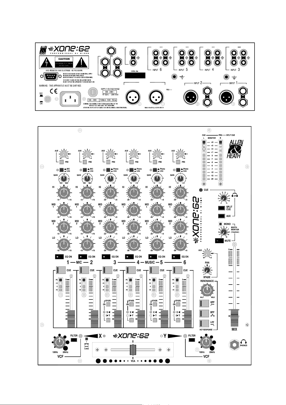
VERSION 1
0
I
USER OPTIONS
AC MAINS IN ~
FUSE
MONO OUT
BOOTH
L
R
CLEAN FEED
L
R
AUX OUT
LINE
RECORD OUT
L
R
CLEAN FEED -10dBV
RIGHT LEFT MIC
PHONO
L
RR
MIX OUT
L
PHONO
LINE LINE
PHONO
L
R
LINE
L/M
R
PHONO LINE
L
R
MIC
LINE
L/M
R
8 XONE:62 Service Manual
Page 9
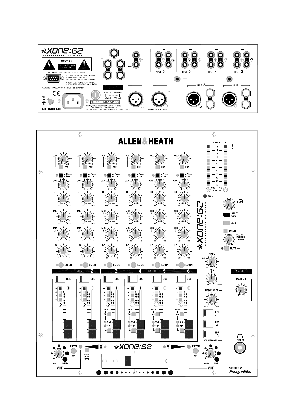
VERSION 2
USER
AC MAINS IN ~
0
I
MONO OUT
BOOTH
RR
CLEAN FEED
FUSE
SERIAL No:
LL
AUX OUT
RECORD OUT
L
R
CLEAN FEED -10dBV
RIGHT
PHONO LINE
L
R
MIX OUT
PHONO
LINE
L
R
MICLEFT MIC
L/M
R
LINE
PHONO
L
R
LINE
LINE
PHONO
L
R
LINE
L/M
R
XONE:62 Service Manual 9
Page 10
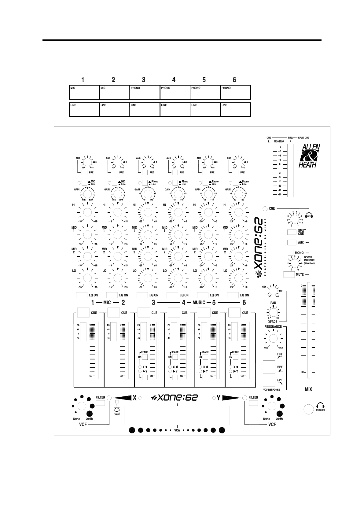
XONE:464 VERSION 1 - CUE SHEET
Photocopy and use to log your console settings
10 XONE:62 Service Manual
Page 11
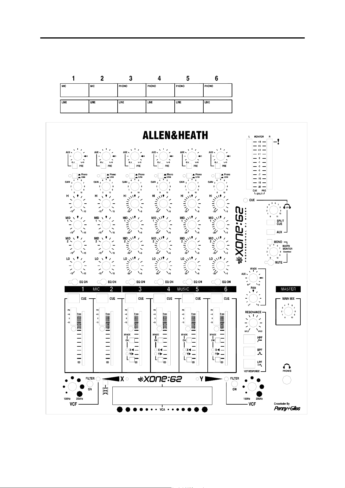
XONE:464 VERSION 2 - CUE SHEET
Photocopy and use to log your console settings
XONE:62 Service Manual 11
Page 12
Specifications
0dBu = 0.775 Volts rms, +4dBu = 1.23V rms 0dBV = 1 Volt rms, -10dBV =
316mV rms
Max output level XLR +26dBu into >2k ohm
TRS +21dBu into >2k ohm
RCA +15dBu into >10k ohm
Headroom Channels +21dB
Mix to output +23dB
Freq response +0/-1dB 20Hz to 40kHz
Distortion < 0.006% THD+noise @1kHz
Crosstalk < 90dB Channel shutoff @1kHz
MIC EIN 22-22kHz -128dB 150 ohm source
Residual noise XLR -90dBu (-94dB S/N)
TRS -84dBu (-84dB S/N)
RCA -92dBu (-84dB S/N)
Mix noise XLR -86dBu (-90dB S/N)
TRS -83dBu (-83dB S/N)
RCA -91dBu (-83dB S/N)
Ch meters Peak reading 4 led
-16, 0, +6, +12 (PK)
Main meters Peak reading 12 led
-20 to +8
Mic EQ 4-Band +/-15dB
100, 250, 2.5k, 10kHz
Music EQ 4-Band +6 / -26dB
100, 250, 2.5k, 10kHz
Ch fader 60mm stereo
Mix fader 100mm stereo or rotary
Crossfader 45mm stereo VCA
Replaceable
Filters Dual stereo VCF
Analogue
Panel Stainless steel
Connector Types
XLR male and female connectors : Pin 2 = hot (+) Pin 3 = cold (-) Pin 1 = GND
TRS input and output connectors : Tip = hot (+) Ring = cold (-) Sleeve = GND
RCA PHONO pin connectors
Input Connections Type Impedance Sensitivity
CH1,2 IN (Mic) Balanced XLR female 2k ohm -45 to –15dBu
(Stereo Line) Unbalanced TRS jack >10k ohm -15 to +15dBu
CH3,4,5,6 (Phono) RCA phono RIAA 47kohm/330pF 2 to 100mV
(Stereo Line) RCA phono >10k ohm -10 to +10dBu
Output Connections Type Impedance Level
MIX OUT L,R (XLR) Balanced XLR male <75 ohm
+4dBu
RECORD OUT RCA phono <600 ohm -10dBV
MONO OUT Impedance balanced TRS jack <600 ohm -2dBu
AUX OUT L,R Impedance balanced TRS jack <75 ohm -2dBu
BOOTH OUT Impedance balanced TRS jack <75 ohm -2dBu
HEADPHONES Tip = L Ring = R 30 to 600 ohm recommended
12 XONE:62 Service Manual
Page 13

Power Supply
Internal switch mode power unit with auto sensing mains input.
MAINS IN socket IEC 3 pin
Power lead Country dependent with moulded mains plug supplied
AC mains 100 to 240V AC @ 50/60Hz
Consumption 30W max
Mains fuse rating 100-240V AC T500mA 20mm
Dimensions and Weights
The console is fitted with rubber feet for desktop operation. An optional screw on rack
ear kit is available for rack or plinth mounting.
Width Height Depth Weight
Desktop 320 mm (12.6”) 105 mm (4.1”) 358 mm (14.1”) 5 kg (11 lbs)
Rack ears fitted 370 mm (14.6”) 105 mm (4.1”) 358 mm (14.1”)
Packed 475 mm (18.7”) 210 mm (8.3”) 395 mm (15.6”) 5.5 kg (12 lbs)
XONE:62 Service Manual 13
Page 14

Optional Rack Ears
Allows permanent fixing in a plinth or rack system. Ears bolt on to the sides of console.
Fix in place using M6 screws or bolts. Contact your Allen & Heath agent for further
information.
Order code:
XONE2:62-RK or XONE2:62-RK19
14 XONE:62 Service Manual
Page 15

Connecting Mains Power
USER
0
I
Earthing
The connection to earth (ground) in an audio system is important for two reasons:
For safety it is important that all equipment earths are connected to mains earth so that
exposed metal parts are prevented from carrying high voltage which can injure or even
kill the operator. It is recommended that the sound engineer check the continuity of the
safety earth from all points in the system including microphone bodies, turntable chassis,
guitar strings, connector cases, equipment panels and so on.
AC MAINS IN ~
FUSE
MONO OUT
BOOTH AUX OUT
L
R
CLEAN FEED
SERIAL No:
L
R
Read the SAFETY INSTRUCTIONS printed at
the front of this Service Manual. Check that the
correct mains lead with moulded plug has been
supplied with the console. The power supply
accommodates mains voltages within the range
100-240V without changing any fuses or settings.
It is standard practice to turn connected power
amplifiers down or off before switching the
console on or off. Ensure that the IEC mains
plug is pressed fully into the rear panel socket
before switching on.
1. SAFETY - To protect the operator from high voltage shock, and
2. AUDIO PERFORMANCE - To minimise the effect of earth
(ground) loops which result in audible hum and buzz, and to
shield the audio signals from interference.
The same earth is also used to shield audio cables from external interference such as the
hum fields associated with power transformers, lighting dimmer buzz, and computer
radiation. Problems arise when the signal sees more than one path to mains earth. An
‘earth loop’ (ground loop) results causing current to flow between the different earth
paths. This condition is usually detected as a mains frequency audible hum or buzz.
To ensure safe and trouble-free operation we recommend the following:
• Have the mains system checked by a qualified electrician. If the supply earthing
is solid to start with you are less likely to experience problems.
• Do not remove the earth connection from the console mains plug. The console
chassis is connected to mains earth through the power cable to ensure your safety.
Audio 0V is connected to the console chassis internally. If problems are encountered
with earth loops operate the audio ‘ground lift’ switches on connected equipment
accordingly, or disconnect the cable screens at one end, usually at the destination.
• Make sure that turntables are correctly earthed. A chassis earth terminal is
provided on the console rear panel to connect to turntable earth straps.
• Use low impedance sources such as microphones and line level equipment rated at
200 ohms or less to reduce susceptibility to interference. The console outputs are
designed to operate at very low impedance to minimise interference problems.
• Use balanced connections where possible as these provide further immunity by
cancelling out interference that may be picked up on long cable runs. To connect an
unbalanced source to a balanced console input, link the cold input (XLR pin 3 or jack
ring) to 0V earth (XLR pin 1 or jack sleeve) at the console. To connect a balanced
XLR output to unbalanced equipment, link the cold output to 0V earth at the console.
• Use good quality cables and connectors and check for correct wiring and reliable
solder joints. Allow sufficient cable loop to prevent damage through stretching.
XONE:62 Service Manual 15
Page 16

Plugging Up The System
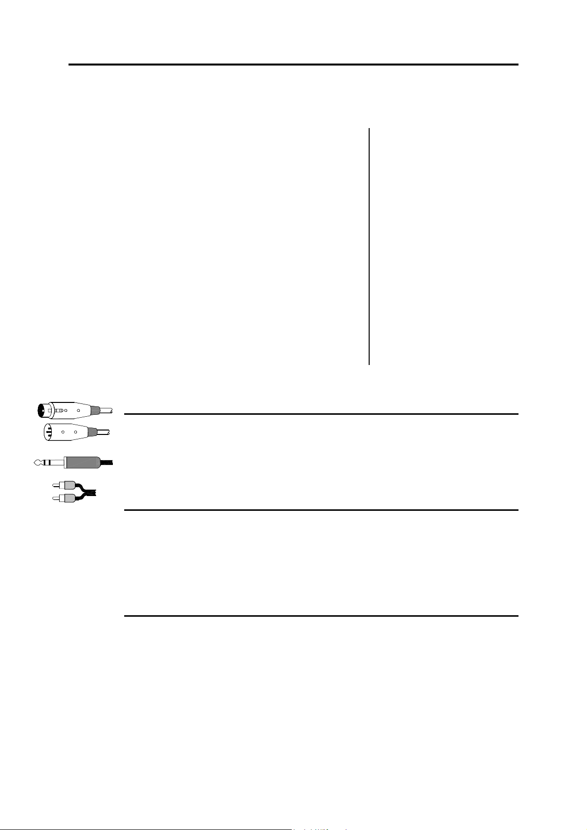
The XONE:62 uses professional grade 3 pin XLR, 1/4" TRS jack and RCA PHONO
sockets. To ensure best performance, we recommend the use of high quality audio
cables and connectors, and that time is taken to check for reliable and accurate cable
assembly. It is well known that most audio system failures are due to faulty
interconnecting leads. The following mating plugs may be used to connect audio signals
to the console:
All input and output XLR connectors are 3 wire differentially balanced. These have 3
connector pins: Pin 1 = ground (screen), Pin 2 = signal hot (+), Pin 3 = signal cold (-).
All the jack sockets are the 3 pole TRS type. These are wired to work with both the
balanced TRS or the unbalanced 2 pole TS type plugs. The sockets have 3 connector
pins: Inputs and outputs are Tip = signal hot (+), Ring = signal cold (-), Sleeve = ground
(screen). Insert connections are Tip = send, Ring = return, Sleeve = ground.
The RCA phono connectors are the 2 wire unbalanced type typical of those found on
equipment such as CD players, turntables and domestic amplifiers.
Avoid reversing + and - on balanced connections as this will result in out of phase signals
(reverse polarity) which may cause signal cancellation effects.
For live work where long cables runs are required, balanced interconnections should be
used. However, interconnections between more affordable 2-wire (signal, ground)
unbalanced equipment and the console are unlikely to cause problems if the cables are
kept short. Refer to the following diagram for unbalanced to balanced connections.
Dealing with Ground Loops, Buzz and Interference
For optimum performance all audio signals should be referenced to a solid, noise-free
ground (earth) point, frequently referred to as the ‘star point’ or ‘clean earth’.
A ground loop is created when the signal has more than one path to ground. Should you
experience hum or buzz caused by ground loops, check first that each piece of
equipment has its own separate path to ground. If so, operate ground lift switches on
connected equipment in accordance with the instruction manuals. Alternatively
disconnect the cable screen at the destination end only. This breaks the offending loop
while still maintaining the screening down the length of the cable.
WARNING For your safety do not remove the earth (ground) connection in the
power lead of the console or connected equipment.
To avoid interference pickup keep audio cables away from mains power units and cables,
thyristor dimmer units or computer equipment. Where this cannot be avoided, cross the
cables at right angles to minimise interference.
16 XONE:62 Service Manual
Page 17

XONE:62 Service Manual 17
Page 18

Replacing the Crossfader
The crossfader on a DJ mixer is heavily used and can suffer considerable wear
and tear. The audio design using VCAs prevents clicks and scratchiness as the
fader wears. However, the movement can become mechanically stiff or sloppy
in time, or become ingrained with dirt and the fader may need replacement.
The XONE:62 crossfader is removable and can easily be replaced in a few
minutes. The spare fader is supplied as a plug-in assembly which can be
ordered through your Allen & Heath dealer.
Note: There are two versions of crossfader assembly. These are not
interchangable. Make sure you order the correct version.
The VERSION 1 model uses the Alps crossfader assembly:
XONE:62 Crossfader Assembly Part number 002-718
The VERSION 2 model uses the Penny & Giles crossfader assembly :
XONE:62 Crossfader Assembly Part number 002-719
To replace either version of crossfader use a medium size cross-point (Pozidriv)
screwdriver to undo and remove the two outer screws on the crossfader plate.
Do not remove the inner screws.
Lift the crossfader assembly up and away from the console panel.
Unplug the cable from the old crossfader or circuit assembly (depending on
version) and plug on the new assembly. Check that the connector is correctly
aligned and seated.
Replace the assembly making sure the cable faces the left side of the console.
Refit the screws and test for correct operation.
18 XONE:62 Service Manual
Page 19

Tips and Troubleshooting
From the User Guide:
For your safety do not remove the EARTH
(ground) connection in the power lead of the
console or connected equipment.
☺ Have your MAINS SYSTEM checked by a
qualified electrician. If the earthing is solid to start
with you are less likely to experience problems.
☺ Use high grade AUDIO CABLES and check
them for reliable connection. It is well known that
many audio system problems are due to faulty
cables and connectors.
In a club or similar installation strict SOUND
LEVEL and noise regulations may apply. Check
that your system levels are correctly set up to
comply.
To avoid damage to your hearing start with
the HEADPHONES level control at minimum and
turn up only as much as is needed to maintain
comfortable listening level. Do not drive
headphones at high listening levels for long periods
of time.
Always switch connected AMPLIFIERS on
last and off first to avoid thumps when the console
and connected equipment is turned on or off.
Reduce gain if the red meter PEAK led
flashes. These warn you that you are near clipping
which may result in system overload and distortion.
The XONE:62 provides plenty of drive and
headroom when operated around the 0 to +6 meter
points. Check that the amplifier / speaker system is
correctly matched and set up for correct levels.
Increasing VCF RESONANCE boosts a
narrow band of selected frequencies. Make sure
you reduce the channel gain if the red peak meters
start to flash. It is best to start experimenting with
this control set to minimum.
☺ If you suspect a console fault. The console
is the heart of the audio system and is often
suspected faulty when a problem occurs. Usually
the fault is found to be with other equipment in the
system, typically the interconnecting leads, input
sources, or level matching between equipment.
Check for source problems by unplugging each
channel in turn listening for a change in symptom.
To check the console, isolate it by unplugging all
sources and outputs leaving just headphones and a
reference source such as a CD player connected.
? I have plugged in a microphone but it does
not work. The XONE:62 is designed to operate
with non-phantom powered dynamic microphones
such as the popular vocal types. Do not use
microphones which require phantom power.
? The stereo channel sounds very distorted
with high level and excessive bass. Only plug
turntables needing RIAA equalisation into CH 3-6
PHONO inputs. Other equipment should be
plugged into the LINE inputs.
? There is a hum on the turntable channels.
Check that the turntable earth strap has been
correctly connected to the console chassis earth
post. Also check that the turntable headshell and
cartridge are correctly aligned and plugged in.
? Only one side of the stereo mix is working.
Check that the XFADE PAN control is not set fully to
either L or R. Also check for bad connections, in
particular turntable headshell and cartridge pins.
? There is feedback. Check that the microphone
is not placed next to the headphones. The mic may
pick up its own signal from the headphones and
feed back. In loud listening conditions feedback can
sometimes be caused by mechanical vibration
through the turntables into the cartridge, or even the
needle resting on a cued turntable starting to
resonate in the groove of the record.
? When the VCF is switched on there is very
little sound. Operate the VCF frequency control to
restore the frequency content of the sound.
? There is no monitor output. Check that a
channel CUE switch is not already selected. This is
indicated by the red CUE led under the monitor
meters. Also check that AUX is not selected.
? There is no stereo channel signal. Check that
the input selector switch is correctly set.
? The crossfader is not working. Make sure the
channel XFADE ON switch is pressed and X or Y
correctly selected.
? The crossfader works backwards. Check that
it has been re-fitted the right way round if previously
removed.
? I have connected a stereo source to a single
input using a Y-adapter but it sounds bad. Do
not connect more than one output to the input.
These adapters are designed to feed one output to
two inputs, not the other way round.
XONE:62 Service Manual 19
Page 20

82 Gain and Operating Levels
It is most important that the system gain and level settings are correctly set. It is well
known that many DJs push the gain to maximum with meters peaking hard in the belief
that they are getting the best from the system. THIS IS NOT THE CASE ! The best can
only be achieved if the system levels are set within the normal operating range and not
allowed to peak. Peaking simply results in signal distortion, not more volume. It is the
specification of the amplifier / speaker system that sets the maximum volume that can be
!
achieved, not the console. The human ear too can fool the operator into believing that
more volume is needed. Be careful as this is in fact a warning that hearing damage will
result if high listening levels are maintained. Remember that it is the QUALITY of the
sound that pleases the ear, not the VOLUME.
Use the GAIN TRIM 1 to match the input source to the normal operating level of the console. Adjust this so that
the CHANNEL METER 4 averages 0dB with loudest moments reading +6. Press the CUE SWITCH 3 to
listen to the signal on headphones and check the level on the expanded range MAIN METERS 9 . Adjust the
CHANNEL FADER 5 and MASTER FADER 6 so that they normally operate in the shaded area near the top.
Make sure the amplifier/speaker system has been correctly calibrated for the loudest volume required at the fader
top position. Boosting the EQ 2 also adds gain to the system. Reduce by turning back the GAIN TRIM 1 if
the meter red peak leds flash. Adjust the HEADPHONES 8 and BOOTH 7 monitor controls for safe
listening levels.
A final note … The human ear is a remarkable organ with the ability to compress or ‘shut down’ when sound
levels become too high. Do not interprete this natural response as a reason to turn the system volume up further
! As the session wears on ear fatigue may set in, and the speaker cones may become hot so
effectiveness of the system and listeners to gain any benefit from increased volume.
The diagram above illustrates the operating
range of the audio signal.
NORMAL OPERATING RANGE. For normal
music the signal should range between –5 and +5
on the meters with average around 0dB. This
allows enough HEADROOM for unexpected
peaks before the signal hits its maximum
CLIPPING voltage and distorts. It also achieves
the best SIGNAL-TO-NOISE-RATIO by keeping
the signal well above the residual NOISE FLOOR
(system hiss). The DYNAMIC RANGE is the
maximum signal swing available between the
residual noise floor and clipping. The XONE:62
provides a massive 110dB dynamic range.
reducing the
BE SENSIBLE, BE SAFE WITH SOUND LEVELS
20 XONE:62 Service Manual
Page 21

Page 22

Page 23

Page 24

Page 25

Page 26

Page 27

Page 28

Page 29

Page 30

Page 31

Page 32

Page 33

Page 34

Page 35

Page 36

Page 37

Page 38

Page 39

 Loading...