


GL-2200

Audio mixing console
*/
5533
PUBLICATION: AP3389
6(59,&(#0$18$/

GL2200
S
ERVICE
M
ANUAL
2
CONTENTS
Introduction ............................................................................................................................3
Service and Technical Support..............................................................................................3
Safety Warning & General Precautions.................................................................................3
The
GL2200
Range & Options ..............................................................................................4
Flightcasing the Console........................................................................................................4
Dimensions ............................................................................................................................4
Specifications & Connections ................................................................................................5
Ordering a
GL2200
Console, Options and Documentation...................................................6
Ordering an Assembly ...........................................................................................................7
Ordering a Spares Kit ............................................................................................................8 - 9
Front Panel Layout.................................................................................................................10
Rear Panel Layout .................................................................................................................11
Block Diagram........................................................................................................................12
GL2200
INPUT Circuit Board component Ident ....................................................................AG3395
GL2200
INPUT Circuit Diagram ............................................................................................C3395
GL2200
STEREO Circuit Board component Ident ................................................................AG3428
GL2200
STEREO Circuit Diagram (Page 1 of 2) ..................................................................C3428
GL2200
STEREO Circuit Diagram (Page 2 of 2) ..................................................................C3428
GL2200
GROUP Circuit Board component Ident..................................................................AG3425
GL2200
GROUP Circuit Diagram (Page 1 of 2)....................................................................C3425
GL2200
GROUP Circuit Diagram (Page 2 of 2)....................................................................C3425
GL2200
LEFT Circuit Board component Ident ......................................................................AG3426
GL2200
LEFT Circuit Diagram (Page 1 of 3) ........................................................................C3426
GL2200
LEFT Circuit Diagram (Page 2 of 3) ........................................................................C3426
GL2200
LEFT Circuit Diagram (Page 3 of 3) ........................................................................C3426
GL2200
RIGHT Circuit Board component Ident....................................................................AG3427
GL2200
RIGHT Circuit Diagram (Page 1 of 2)......................................................................C3427
GL2200
RIGHT Circuit Diagram (Page 2 of 2)......................................................................C3427
GL2200
OSC/NOISE Circuit Board component Ident ...........................................................AG3519
GL2200
OSC/NOISE Circuit Diagram...................................................................................C3519
GL2200
PSU Circuit Board component Ident........................................................................AG3504
GL2200
PSU Circuit Diagram................................................................................................C3504
GL2200
Service Manual AP3389 Issue 1. Copyright © 1999 Allen & Heath. All rights reserved
M
ANUFACTURED
I
N
E
NGLAND BY
: A
LLEN
& H
EATH
A
GENT
:
ALLEN & HEATH
Kernick Industrial Estate
Penryn, Cornwall, TR10 9LU. UK
http://www.allen-heath.com
A DIVISION OF HARMAN INTERNATIONAL INDUSTRIES Ltd
Warning to the Service Engineer
Allen & Heath warns that an y unauthorised changes or m odifications to the
GL2200
unit may
invalidate the legal com pliance of the unit and could void the us er’s authority to operate the
equipment.

GL2200
S
ERVICE
M
ANUAL
3
Introduction
The information pres ented in this manual is inten ded for competent technical personnel to carry out
service and product su ppor t for the
GL2200
range of consol es. W e as sum e that the rea der is f amiliar
with the related el ectronic th eory and audio te rminolog y, and is able to c arry out servic ing, f aultfin ding
and repair of audio equipment of this type. Service personnel should also be familiar with audio
systems, mains earthing and power requirements, as well as handling precautions.
For information on the configuration, operation and application of the
GL2200
range, please
refer to
GL2200
User Guide (A&H Part no: AP3388).
Whilst we believe the information in this manual to be reliable we do not assume responsibility for
inaccuracies. We also reserve the right to make changes in the interest of further product
development.
Service and Technical Support
Under normal condit ions the
GL2200
does not require us er maintenance or internal c alibration. Any
service work required should be carried out by qualified service personnel only.
We are able to offer further pr oduct support throu gh our world-wid e network of approved dealers and
service agents. You can also access our Web site on the Internet for information on our product
range, assistance with your technical queries or simply to chat about audio matters. To help us
provide the most efficient service please keep a record of the console serial number, the date and
place of purchase to be quoted in any communication regarding this product.
General Precautions
Your
GL2200
is ruggedly constructed to give many years of reliable operation. However, you will
extend the life of the console and preserve its cosmetics by applying these simple common sense
precautions.
x
Avoid storing or using the mixing consol e in conditions of ex cessive heat or cold, or in positions
where it is likely to be subject to vibration, dust, dirt or moisture.
x
Do not use any liquids to clean the co ntrol surface of the c onsole, a soft dr y brush or dry lint-f ree
cloth is ideal.
x
Use only water or ethyl alcohol to clean t he trim and scribble strips. Other solvents may cause
damage to paint or plastic parts.
x
T he faders, switches and potentiom eters are lubric ated for life. T he use of elec trical lu bricants on
these parts is not recommended.
x
Av oid using t he conso le close t o strong s ources of electrom agnetic radiat ion ( e.g. vi deo m onitors,
high power electric cabling): this may cause degradation of the audio quality due to induced
voltages in connecting leads and ch assis. For the same r eason, always site any ex ternal power
supply away from the unit.
SAFETY WARNING!
Mains electricity is dangerous and can kill. M ains voltage
is present within the console power supply unit.
Do not remove the power supply cover with mains
electricity connected. To ensure your safet y, mains earth
is connected to the chassis through the power lead. Do
not remove this mains earth connection.
To avoid the risk of fire, repla ce the mains fuse only w ith
the correct value and type as indicated on the power
su
pp
l
y
unit.
The internal power supply unit contains no serviceable components
and must be replaced as a complete unit if a failure occurs.
GL2200
S
ERVICE
M
ANUAL
4
The
GL2200
Range
12, 16, 24 and 32 channel models
GL2200-412 10 mono, 2 stereo, 4 groups, 6 aux, 2 stereo returns, L, R, Mono sum
GL2200-416 14 mono, 2 stereo, 4 groups, 6 aux, 2 stereo returns, L, R, Mono sum
GL2200-424 22 mono, 2 stereo, 4 groups, 6 aux, 2 stereo returns, L, R, Mono sum
GL2200-432 30 mono, 2 stereo, 4 groups, 6 aux, 2 stereo returns, L, R, Mono sum
Options
GL2200-SL1 Sys-link buss expander, one kit per console
RPS9 2U rack mount power supply for backup
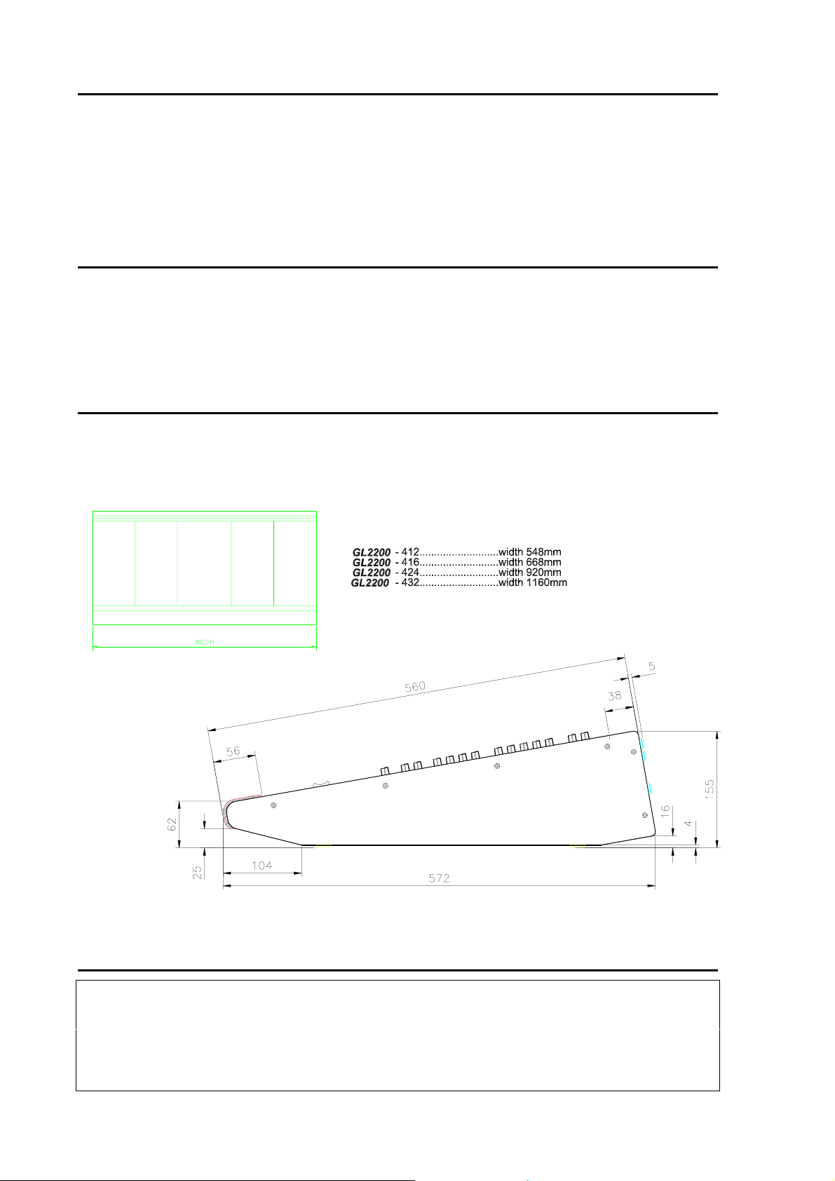
Flightcasing The Console
If the console is to b e regularly moved we rec ommend that it is insta lled in a foam-line d flightcase.
At all times avoid applying excessive force to any knobs, switches or connectors.
Dimensions for flightcasing the console are shown below:
Dimensions
Unpacked Packed
Width depth height weight(kg) Width depth height weight(kg)
GL2200-412........................548............ 572............155 ............16.................... 700............750............280............ 20
GL2200-416........................668............ 572............155 ............18.................... 815............750............280............ 23
GL2200-424........................920............ 572............155 ............24.................... 1065.......... 750............280............ 29
GL2200-432........................1160.......... 572............155 ............30.................... 1325..........750 ............280............ 35
RPS9 power supply............483............ 140............ 96............. 6..................... 540............ 270........... .180............ 8

GL2200
S
ERVICE
M
ANUAL
5
Specifications
0 dBu = 0.775 Volts rms 0 dBV = 1 Volt rms
HEADROOM
:............................................................ +21dB
MAX OUTPUT
: ..............……XLR +25dBu 2kohm max load
...........................................JACK +21dBu 2kohm max load
METERS
: L, R……………….peak reading 12 bar LED
Groups 1-4……….peak reading 4 segment LED
Channels…………peak reading 4 segment LED
PEAK LEDs
: ........................... Turn on 5dB before clipping
FREQUENCY RESPONSE
referred to 1kHz @ +4dBu:
Any input to any output....................20Hz to 30kHz +0/-1dB
DISTORTION
: THD+Noise @ +14dBu 1kHz
Mic in to L-R output, 40dB gain ................................0.010%
Line in to L-R output, 0dB gain.................................0.008%
CMRR
CROSSTALK:
Referred to driven channel @ 1kHz
Adjacent channel ……………………………………... < -94dB
Channel fader off.....................................................< -90dB
Channel mute on.....................................................< -90dB
Channel Pan pot isolation........................................< -80dB
NOISE
: Measured rms, 22kHz bandwidth
Mic input EIN (150 ohm source).............................< -128dB
Line preamp, 0dB gain...........................................< -90dBu
L-R output residual noise.....................< -94dBu (98dB S/N)
L-R faders ‘0’, nothing routed...............< -90dBu (94dB S/N)
L-R mix noise (16 channels routed).....< -84dBu (88dB S/N)
Group, faders ‘0’, nothing routed..........< -91dBu (95dB S/N)
Group mix noise (16 channels routed).< -84dBu (88dB S/N)
POWER SUPPLY
:....................100 to 240V AC @ 47/63Hz
...................................Internal, autosensing AC mains input
Power consumption:..............................................60W max
Mains Fuse rating 100-240VAC: ...............T1A 250V 20mm
Mic in, 40dB gain @ 1kHz......................................... >88dB
Connections
INPUTS:
Mic in .............................XLR.........................pin 2 hot, 3 cold, balanced....................>2k Ohm..........variable -60 to -20dBu
Line in............................XLR......................... pin 2 hot, 3 cold, balanced....................>10k Ohm........variable -30 to +10dBu
or TRS jack.................tip hot, ring cold, balanced....................>10k Ohm........variable -30 to +10dB u
Stereo Ch Line in ...........TRS jack.................tip hot, unbalanced................................>8k Ohm ......... -20dBu min
Stereo Return.................TRS jack.................tip hot, unbalanced................................>6k Ohm ..........-10dBV min
2-Track Return...............RCA PHONO..........unbalanced...........................................>10k Ohm........-10dBV min
Insert Return..................TRS jack .................tip send, ring return, unbalanced...........>6k Ohm ..........0dBu (chan), -2dBu (out)
OUTPUTS:
L-R, Group out ...............XLR.........................pin 2 hot, 3 cold, balanced....................<75 Ohm .........+4dBu, +27dBu max
Direct out........................TRS jack.................tip hot, impedance balanced.................<75 Ohm .........0dBu
2-Track sends................RCA PHONO..........unbalanced...........................................<75 Ohm .........variable +21dBu max
Aux out..........................TRS jack.................tip hot, impedance balanced .................<75 Ohm .........variable +21dBu max
Mono out........................XLR.........................tip hot, ring cold, balanced....................<75 Ohm.........+4dBu, +27dBu max
Insert send.....................TRS jack .................tip send, ring return, unbalanced...........<75 Ohm .........0dBu (chan), -2dBu (out)
Monitor out.....................TRS jack.................tip left, ring right, unbalanced................<75 Ohm .........variable +21dBu max
Phones out.....................TRS jack .................tip left, ring right....................................for stereo headphones 30 to 600 Ohms

GL2200
S
ERVICE
M
ANUAL
6
Ordering a
GL2200
Console
To order a new console please specify the model number and AC mains voltage required.
MODEL DESCRIPTION ORDER CODE
GL2200
12 Channel 10 mono + 2 stereo input channels GL2200-412/volts
GL2200
16 Channel 14 mono + 2 stereo inputs channels GL2200-416/volts
GL2200
24 Channel 22 mono + 2 stereo inputs channels GL2200-424/volts
GL2200
32 Channel 30 mono + 2 stereo inputs channels GL2200-432/volts
Ordering an Option
To order an option please specify the serial number of the console that is to have the option fitted.
MODEL DESCRIPTION ORDER CODE
GL2200-SL1
GL2200
SYS-LINK
KIT GL2200-SL1
GL2200 Balanced Output IC option AE0302
RPS9
2U external linear
power supply RPS9/volts
Manuals and Support Documentation
DESCRIPTION ORDER CODE
GL2200
User Guide AP3388
GL2200
Service Manual AP3389
GL2200
Brochure AP3390
GL2200
SYS-LINK Fitting Instructions AP3622
GL2200
SYS-LINK Application Note AP3623
RPS9
User Guide AP0334
Service Tools
The tools required to service the
GL2200
are standard to an electronic service workshop and are
easily obtainable. The following items are necessary for disassembly and service access:
1-point Crosshead screwdriver (M3, 4AB) AT0004
2-point Crosshead screwdriver (M4, 6AB) AT0002
11mm AF Nutdriver (potentiometer nuts)
12mm AF Nutdriver (jack nuts)

GL2200
S
ERVICE
M
ANUAL
7
Ordering an Assembly
The following assemblies are supplied fully tested. Please note that several of these need to be
assigned according to their position in the console. This is achieved by soldering wire links or
assignment pads. It is best to check the assignm ent s ett ings of the as s embly you are replacing bef or e
removing it from the console. Please quote the description and order code for the part required.
Printed Circuit Board (PCB) Assemblies:
* specify position of PCB assembly
Mono Input & Connector PCB assembly 002-412
Stereo Input & Connector PCB assembly 002-442
* Group PCB assembly 002-439
OSC/Noise PCB assembly 002-453
Left PCB assembly 002-440
Right PCB assembly 002-441
Switch Mode PSU assembly (12 & 16) 002-456
Switch Mode PSU assembly (24 & 32) 002-457
IDC connector harnesses:
GL2200-412 20 way Main harness AL3535
GL2200-416 20 way Main harness AL3536
GL2200-424 20 way Main harness AL3537
GL2200-432 20 way Main harness AL3538
The Chassis Trim
GL2200 (all formats) Left & Right Chassis side trims AA2539-L/R
Write-on strip (specify console size) AK0327

GL2200
S
ERVICE
M
ANUAL
8
Ordering a Spares Kit
It is recommended th at the s pares k it order c ode
002-481
is held and maintained by the servic e agent
to enable in-field service repairs to the
GL2200
independent of the ALLEN & HEATH factory.
Commonly available items such as resistors, capacitors, tools and soldering equipment are not
included. The contents of the kit are l isted be low and are s upplie d in a cabin et of dra wers. Indi vidual
spare parts may be ordered. Please quote the description and order code for the part required.
DESCRIPTION ORDER CODE QTY
Fixings:
Screw 4AB x 5/16 CSK Pozi Black AB0059 5
Screw 6AB x 3/8 Pan Pozi Black AB0062 10
Screw M3 x 6mm Pan Pozi Black AB0072 5
Screw M3 x 8mm Pan Pozi Black AB0073 10
Screw M3 x 12mm Pan Pozi Black AB0078 5
Screw M3 x 16mm Pan Pozi Black AB0079 5
Nylock Nut M3 AB0102 5
Screw M3 x 4mm Pan Pozi Black AB0233 10
Screw 4AB x ¼ Pan Pozi Plated AB0252 4
Screw 6B x ¼ Trunc Pozi Zinc AB2083 10
Screw 4 x 5/16 Pan Pozi Plastite AB2771 5
Screw 6B x 5/16 Pan Pozi Black AB2809 5
Screw 4 x 5/16 Poly Pan Pozi AB2810 10
Knobs and caps:
Knob Red & Grey 11mm D AJ2074 10
Knob Blue & Grey 11mm D AJ2075 10
Knob Light Blue & Grey 11mm D AJ2076 10
Knob Green & Grey 11mm D AJ2077 10
Knob Dark Grey & Grey 11mm D AJ2078 10
Knob Yellow & Grey 11mm D AJ2079 10
Knob Brown & Grey 11mm D AJ2080 10
Button 5.5mm Square Grey AJ2864 10
Button 10 x 5mm Rectangular Grey AJ2865 10
Button Round Black AJ2887 1
Button 5.5mm Square White AJ2960 10
Button 5.5mm Square Red AJ2961 10
Button 10 x 5mm Rectangular White AJ2962 10
Button 10 x 5mm Rectangular Black AJ3228 3
Fader Knob 11mm White+Black Line AJ8078 10
Fader Knob 11mm Red+Black Line AJ8079 5
Fader Knob 11mm Yellow+Black Line AJ8080 5
Fader Knob 11mm Blue+Black Line AJ8081 5
Faders, Potentiometers, Switches and connectors:
Pot 10KC x 2 (103C 14mm wide) AI0150 5
Pot 20KK (203K 11mm wide) AI8003 5
Pot 20KB centre click (203B 11mm wide) AI8004 5
Pot 200KC x 2 (204C 11mm wide) AI8005 5
Pot 20KB x 2 centre click (14mm wide) AI8006 5
Pot 20KK x 2 (203K 14mm wide) AI8007 5

GL2200
S
ERVICE
M
ANUAL
9
Pot 10K centre click (103AC 14mm wide) AI8008 5
Pot 5K (502RD 11mm wide) AI8111 5
Fader 10KA x 2 60mm AI8051 5
Fader 10KD 100mm AI8117 10
Fader 10KD x 2 100mm AI8118 5
Switch 2PCO Latching 90 Deg AL0162 5
Switch 4PCO Latching AL0333 5
Switch 2PCO Momentary AL0374 5
Jack Socket Headphone AL0328 1
XLR 3 Pin Female Vertical PCB Mount AL2410 5
XLR 3 Pin Male Vertical PCB Mount AL2411 5
Molex 0.1” Male 10 Pin 90 Deg AL2572 3
Molex 0.1” Female 10 way Straight AL2573 3
Jack Socket ¼” Stereo Unswitched AL3407 5
Jack Socket ¼” Stereo Switched AL3410 5
Pot Nut 9mm AB8050 10
LEDs and Semiconductors:
Transistor BC549 NPN AE0020 3
Transistor BC638 PNP AE0037 2
Transistor BC637 NPN AE0068 2
Transistor 2N4403 PNP AE0273 5
Transistor BC556B PNP AE3001 2
Transistor 2SB737 PNP AE8069 5
IC Op-Amp TL072 AE0046 5
IC LM339N Quad Comparator AE0071 2
IC CMOS 4053B AE0117 1
IC Op-Amp NE5532N AE0221 5
LED 3mm T1 Yellow AE0084 5
LED 3mm T1 Green AE0085 5
LED 3mm T1 Red AE0086 5
LED Bar Rectangular 12 Way AE2701 1
LED 5 x 2mm Rectangular Red Flat Top AE3502 10
Power Supply:
Mains Lead IEC-2pin EURO AH0205 -
Mains Lead IEC-3pin UK AH0206 -
Mains Lead IEC-3pin US (C33) AH0323 -
Mains Fuse 20mm 1A Anti-Surge AL0305 10
Miscellaneous:
GL2200-412 Packing Assembly 002-435 -
GL2200-416 Packing Assembly 002-436 -
GL2200-424 Packing Assembly 002-437 -
GL2200-432 Packing Assembly 002-438 -
Flex Cable 12 Way 90mm AH2228 5
GL2200
S
ERVICE
M
ANUAL
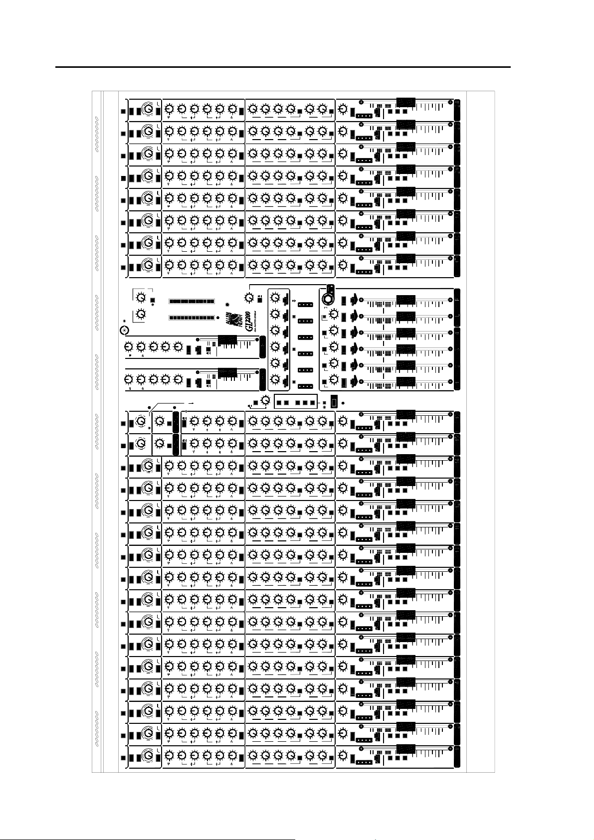
10
GL2200
FRONT PANEL
1-2
3-4
PEAK
L-R
PFL
0
SIG
+6
ODD
L
6
AUX
AUX
5
AUX
4
AUX
3
2
AUX
1
AUX
EVEN
R
MUTE
EQ IN
1
Ø
100Hz
HF
12kHz
-15
0
+15
500Hz
3kHz
15kHz
-15
0
+15
MF1
250Hz
35Hz
1kHz
-15
+15
0
MF2
-15
+15
0
60Hz
LF
PRE
PAN
C
MUTE
60dB
LINE
50
250Hz
MF2
2.5kHz
MF1
L-R
20
10
30
40
TO
MIC
LINE
+15
-15
0
+15
-15
0
+15
-15
0
+15
-15
0
ODD
L
EVEN
R
C
PEAK
0
SIG
+6
1-2
3-4
L-R
+6
OO
0
+6
OO
0
+6
OO
0
+6
OO
0
+6
OO
0
+6
OO
0
1kHz OSC
PINK NOISE
L-R
GRP
1-4
AUX
1-2
AUX
3-4
AUX
5-6
OSC/NOIS E
ON
TALK
MIC TO TALK
+15
-15
+15
-15
0
1
AUX
+6
OO
0
2
AUX
+6
OO
0
ODD
L
R
EVEN
BAL
MUTE
L-R
1-2
LAMP
1
AUX
2
AUX
3
AUX
4
AUX
5
AUX
6
AUX
PEAK
0
SIG
+6
PEAK
0
SIG
+6
PEAK
0
SIG
+6
PEAK
0
SIG
+6
PEAK
0
SIG
+6
PEAK
0
SIG
+6
PFL/AFL
REPLAY
TO
L-R
RECORD
SEND
2-TRACK
RETURN
AUX1
AUX2
AUX3
AUX4
AUX5
AUX6
2
1
0
4
3
8
10
9
6
5
7
MONITOR
LEV
L-R
2-TRK
1
4
3
2
R
L
PAN
L-R
MONO OUT
M
2
1
3
4
L
R
5
5
OO
C
C
C
L
R
C
PFL/AF
L
POWER
30
20
10
0
5
5
+3
+6
+9
-16
-20
-12
-9
-6
-3
-30
0
+16
ENABLE
MIC TO TALK
L
R
MONITOR
O
O
+6
O
O
+6
O
O
+6
O
O
+6
O
O
+6
O
O
+6
0
0
0
0
0
0
48V
MUTE
MUTE
MUTE
MUTE
MUTE
OO
+10
0
OO
+10
0
OO
+10
0
OO
+10
0
OO
+10
0
OO
+10
0
2
1
0
4
3
8
10
9
6
5
7
12kHz
HF
AFL
AFL
AFL
AFL
AFL
AFL
AFL
AFL
AFL
AFL
AFL
AFL
PRE
10
20
30
10
0
6
AUX
AUX
5
AUX
4
AUX
3
2
AUX
1
AUX
EQ IN
PRE
BAL
PRE
PFL
5
5
OO
10
20
30
10
0
STEREO
25-26
STEREO
27-28
HF
12kHz
60Hz
LF
GAIN
15
Ø
48V
MIC
60dB
LINE
50
L-R
20
10
30
40
TO
MIC
LINE
GAIN
16
Ø
48V
MIC
GAIN
LINE
250Hz
MF2
2.5kHz
MF1
+15
-15
0
+15
-15
0
+15
-15
0
+15
-15
0
EQ IN
HF
12kHz
60Hz
LF
+6
OO
0
+6
OO
0
+6
OO
0
+6
OO
0
+6
OO
0
+6
OO
0
6
AUX
AUX
5
AUX
4
AUX
3
2
AUX
1
AUX
PRE
PRE
MUTE
ODD
L
EVEN
R
C
PEAK
0
SIG
+6
L-R
BAL
PFL
5
5
10
0
1-2
3-4
OO
10
20
30
PFL
60Hz
LF
OO
10
RETURN
+15
-15
+15
-15
0
1
AUX
+6
OO
0
2
AUX
+6
OO
0
ODD
L
R
EVEN
BAL
MUTE
30
20
10
0
5
5
12kHz
HF
PFL
60Hz
LF
OO
10
STEREO
L-R
3-4
RETURN
STEREO
GRP/AUX 1 -2
REVERSE
GRP/AUX 3 -4
REVERSE
L-R/AUX 5-6
REVERSE
MUTE
PAN
L-R
PAN
L-R
PAN
L-R
OO
+10
0
L
R
L
R
L
R
WEDGE MONITOR
OO
20
30
10
5
0
5
10
OO
20
30
10
5
0
5
10
OO
20
30
10
5
0
5
10
OO
20
30
10
5
0
5
10
OO
20
30
10
5
0
5
10
OO
20
30
10
5
0
5
10
OO
+10
0
OO
+10
0
1-2
3-4
PEAK
L-R
PFL
0
SIG
+6
ODD
L
6
AUX
AUX
5
AUX
4
AUX
3
2
AUX
1
AUX
EVEN
R
MUTE
EQ IN
2
Ø
100Hz
HF
12kHz
-15
0
+15
500Hz
3kHz
15kHz
-15
0
+15
MF1
250Hz
35Hz
1kHz
-15
+15
0
MF2
-15
+15
0
60Hz
LF
PRE
PAN
C
5
5
OO
O
O
+6
O
O
+6
O
O
+6
O
O
+6
O
O
+6
O
O
+6
0
0
0
0
0
0
48V
PRE
10
20
30
10
0
1-2
3-4
PEAK
L-R
PFL
0
SIG
+6
ODD
L
6
AUX
AUX
5
AUX
4
AUX
3
2
AUX
1
AUX
EVEN
R
MUTE
EQ IN
3
Ø
100Hz
HF
12kHz
-15
0
+15
500Hz
3kHz
15kHz
-15
0
+15
MF1
250Hz
35Hz
1kHz
-15
+15
0
MF2
-15
+15
0
60Hz
LF
PRE
PAN
C
5
5
OO
O
O
+6
O
O
+6
O
O
+6
O
O
+6
O
O
+6
O
O
+6
0
0
0
0
0
0
48V
PRE
10
20
30
10
0
1-2
3-4
PEAK
L-R
PFL
0
SIG
+6
ODD
L
6
AUX
AUX
5
AUX
4
AUX
3
2
AUX
1
AUX
EVEN
R
MUTE
EQ IN
4
Ø
100Hz
HF
12kHz
-15
0
+15
500Hz
3kHz
15kHz
-15
0
+15
MF1
250Hz
35Hz
1kHz
-15
+15
0
MF2
-15
+15
0
60Hz
LF
PRE
PAN
C
5
5
OO
O
O
+6
O
O
+6
O
O
+6
O
O
+6
O
O
+6
O
O
+6
0
0
0
0
0
0
48V
PRE
10
20
30
10
0
1-2
3-4
PEAK
L-R
PFL
0
SIG
+6
ODD
L
6
AUX
AUX
5
AUX
4
AUX
3
2
AUX
1
AUX
EVEN
R
MUTE
EQ IN
5
Ø
100Hz
HF
12kHz
-15
0
+15
500Hz
3kHz
15kHz
-15
0
+15
MF1
250Hz
35Hz
1kHz
-15
+15
0
MF2
-15
+15
0
60Hz
LF
PRE
PAN
C
5
5
OO
O
O
+6
O
O
+6
O
O
+6
O
O
+6
O
O
+6
O
O
+6
0
0
0
0
0
0
48V
PRE
10
20
30
10
0
1-2
3-4
PEAK
L-R
PFL
0
SIG
+6
ODD
L
6
AUX
AUX
5
AUX
4
AUX
3
2
AUX
1
AUX
EVEN
R
MUTE
EQ IN
6
Ø
100Hz
HF
12kHz
-15
0
+15
500Hz
3kHz
15kHz
-15
0
+15
MF1
250Hz
35Hz
1kHz
-15
+15
0
MF2
-15
+15
0
60Hz
LF
PRE
PAN
C
5
5
OO
O
O
+6
O
O
+6
O
O
+6
O
O
+6
O
O
+6
O
O
+6
0
0
0
0
0
0
48V
PRE
10
20
30
10
0
1-2
3-4
PEAK
L-R
PFL
0
SIG
+6
ODD
L
6
AUX
AUX
5
AUX
4
AUX
3
2
AUX
1
AUX
EVEN
R
MUTE
EQ IN
7
Ø
100Hz
HF
12kHz
-15
0
+15
500Hz
3kHz
15kHz
-15
0
+15
MF1
250Hz
35Hz
1kHz
-15
+15
0
MF2
-15
+15
0
60Hz
LF
PRE
PAN
C
5
5
OO
O
O
+6
O
O
+6
O
O
+6
O
O
+6
O
O
+6
O
O
+6
0
0
0
0
0
0
48V
PRE
10
20
30
10
0
1-2
3-4
PEAK
L-R
PFL
0
SIG
+6
ODD
L
6
AUX
AUX
5
AUX
4
AUX
3
2
AUX
1
AUX
EVEN
R
MUTE
EQ IN
8
Ø
100Hz
HF
12kHz
-15
0
+15
500Hz
3kHz
15kHz
-15
0
+15
MF1
250Hz
35Hz
1kHz
-15
+15
0
MF2
-15
+15
0
60Hz
LF
PRE
PAN
C
5
5
OO
O
O
+6
O
O
+6
O
O
+6
O
O
+6
O
O
+6
O
O
+6
0
0
0
0
0
0
48V
PRE
10
20
30
10
0
1-2
3-4
PEAK
L-R
PFL
0
SIG
+6
ODD
L
6
AUX
AUX
5
AUX
4
AUX
3
2
AUX
1
AUX
EVEN
R
MUTE
EQ IN
9
Ø
100Hz
HF
12kHz
-15
0
+15
500Hz
3kHz
15kHz
-15
0
+15
MF1
250Hz
35Hz
1kHz
-15
+15
0
MF2
-15
+15
0
60Hz
LF
PRE
PAN
C
5
5
OO
O
O
+6
O
O
+6
O
O
+6
O
O
+6
O
O
+6
O
O
+6
0
0
0
0
0
0
48V
PRE
10
20
30
10
0
1-2
3-4
PEAK
L-R
PFL
0
SIG
+6
ODD
L
6
AUX
AUX
5
AUX
4
AUX
3
2
AUX
1
AUX
EVEN
R
MUTE
EQ IN
10
Ø
100Hz
HF
12kHz
-15
0
+15
500Hz
3kHz
15kHz
-15
0
+15
MF1
250Hz
35Hz
1kHz
-15
+15
0
MF2
-15
+15
0
60Hz
LF
PRE
PAN
C
5
5
OO
O
O
+6
O
O
+6
O
O
+6
O
O
+6
O
O
+6
O
O
+6
0
0
0
0
0
0
48V
PRE
10
20
30
10
0
1-2
3-4
PEAK
L-R
PFL
0
SIG
+6
ODD
L
6
AUX
AUX
5
AUX
4
AUX
3
2
AUX
1
AUX
EVEN
R
MUTE
EQ IN
11
Ø
100Hz
HF
12kHz
-15
0
+15
500Hz
3kHz
15kHz
-15
0
+15
MF1
250Hz
35Hz
1kHz
-15
+15
0
MF2
-15
+15
0
60Hz
LF
PRE
PAN
C
5
5
OO
O
O
+6
O
O
+6
O
O
+6
O
O
+6
O
O
+6
O
O
+6
0
0
0
0
0
0
48V
PRE
10
20
30
10
0
1-2
3-4
PEAK
L-R
PFL
0
SIG
+6
ODD
L
6
AUX
AUX
5
AUX
4
AUX
3
2
AUX
1
AUX
EVEN
R
MUTE
EQ IN
12
Ø
100Hz
HF
12kHz
-15
0
+15
500Hz
3kHz
15kHz
-15
0
+15
MF1
250Hz
35Hz
1kHz
-15
+15
0
MF2
-15
+15
0
60Hz
LF
PRE
PAN
C
5
5
OO
O
O
+6
O
O
+6
O
O
+6
O
O
+6
O
O
+6
O
O
+6
0
0
0
0
0
0
48V
PRE
10
20
30
10
0
1-2
3-4
PEAK
L-R
PFL
0
SIG
+6
ODD
L
6
AUX
AUX
5
AUX
4
AUX
3
2
AUX
1
AUX
EVEN
R
MUTE
EQ IN
13
Ø
100Hz
HF
12kHz
-15
0
+15
500Hz
3kHz
15kHz
-15
0
+15
MF1
250Hz
35Hz
1kHz
-15
+15
0
MF2
-15
+15
0
60Hz
LF
PRE
PAN
C
5
5
OO
O
O
+6
O
O
+6
O
O
+6
O
O
+6
O
O
+6
O
O
+6
0
0
0
0
0
0
48V
PRE
10
20
30
10
0
1-2
3-4
PEAK
L-R
PFL
0
SIG
+6
ODD
L
6
AUX
AUX
5
AUX
4
AUX
3
2
AUX
1
AUX
EVEN
R
MUTE
EQ IN
14
Ø
100Hz
HF
12kHz
-15
0
+15
500Hz
3kHz
15kHz
-15
0
+15
MF1
250Hz
35Hz
1kHz
-15
+15
0
MF2
-15
+15
0
60Hz
LF
PRE
PAN
C
5
5
OO
O
O
+6
O
O
+6
O
O
+6
O
O
+6
O
O
+6
O
O
+6
0
0
0
0
0
0
48V
PRE
10
20
30
10
0
EQ IN
Ø
100Hz
HF
12kHz
-15
0
+15
500Hz
3kHz
15kHz
-15
0
+15
MF1
250Hz
35Hz
1kHz
-15
+15
0
MF2
-15
+15
0
60Hz
LF
48V
1-2
3-4
PEAK
L-R
PFL
0
SIG
+6
ODD
L
6
AUX
AUX
5
AUX
4
AUX
3
2
AUX
1
AUX
EVEN
R
MUTE
PRE
PAN
C
5
5
OO
O
O
+6
O
O
+6
O
O
+6
O
O
+6
O
O
+6
O
O
+6
0
0
0
0
0
0
PRE
10
20
30
10
0
17
FOH
STAGE MONITOR
OO
20
10
0
GAIN
LINE
OO
20
10
0
5
6
EQ IN
Ø
100Hz
HF
12kHz
-15
0
+15
500Hz
3kHz
15kHz
-15
0
+15
MF1
250Hz
35Hz
1kHz
-15
+15
0
MF2
-15
+15
0
60Hz
LF
48V
1-2
3-4
PEAK
L-R
PFL
0
SIG
+6
ODD
L
6
AUX
AUX
5
AUX
4
AUX
3
2
AUX
1
AUX
EVEN
R
MUTE
PRE
PAN
C
5
5
OO
O
O
+6
O
O
+6
O
O
+6
O
O
+6
O
O
+6
O
O
+6
0
0
0
0
0
0
PRE
10
20
30
10
0
18
EQ IN
Ø
100Hz
HF
12kHz
-15
0
+15
500Hz
3kHz
15kHz
-15
0
+15
MF1
250Hz
35Hz
1kHz
-15
+15
0
MF2
-15
+15
0
60Hz
LF
48V
1-2
3-4
PEAK
L-R
PFL
0
SIG
+6
ODD
L
6
AUX
AUX
5
AUX
4
AUX
3
2
AUX
1
AUX
EVEN
R
MUTE
PRE
PAN
C
5
5
OO
O
O
+6
O
O
+6
O
O
+6
O
O
+6
O
O
+6
O
O
+6
0
0
0
0
0
0
PRE
10
20
30
10
0
19
EQ IN
Ø
100Hz
HF
12kHz
-15
0
+15
500Hz
3kHz
15kHz
-15
0
+15
MF1
250Hz
35Hz
1kHz
-15
+15
0
MF2
-15
+15
0
60Hz
LF
48V
1-2
3-4
PEAK
L-R
PFL
0
SIG
+6
ODD
L
6
AUX
AUX
5
AUX
4
AUX
3
2
AUX
1
AUX
EVEN
R
MUTE
PRE
PAN
C
5
5
OO
O
O
+6
O
O
+6
O
O
+6
O
O
+6
O
O
+6
O
O
+6
0
0
0
0
0
0
PRE
10
20
30
10
0
20
EQ IN
Ø
100Hz
HF
12kHz
-15
0
+15
500Hz
3kHz
15kHz
-15
0
+15
MF1
250Hz
35Hz
1kHz
-15
+15
0
MF2
-15
+15
0
60Hz
LF
48V
1-2
3-4
PEAK
L-R
PFL
0
SIG
+6
ODD
L
6
AUX
AUX
5
AUX
4
AUX
3
2
AUX
1
AUX
EVEN
R
MUTE
PRE
PAN
C
5
5
OO
O
O
+6
O
O
+6
O
O
+6
O
O
+6
O
O
+6
O
O
+6
0
0
0
0
0
0
PRE
10
20
30
10
0
21
EQ IN
Ø
100Hz
HF
12kHz
-15
0
+15
500Hz
3kHz
15kHz
-15
0
+15
MF1
250Hz
35Hz
1kHz
-15
+15
0
MF2
-15
+15
0
60Hz
LF
48V
1-2
3-4
PEAK
L-R
PFL
0
SIG
+6
ODD
L
6
AUX
AUX
5
AUX
4
AUX
3
2
AUX
1
AUX
EVEN
R
MUTE
PRE
PAN
C
5
5
OO
O
O
+6
O
O
+6
O
O
+6
O
O
+6
O
O
+6
O
O
+6
0
0
0
0
0
0
PRE
10
20
30
10
0
22
EQ IN
Ø
100Hz
HF
12kHz
-15
0
+15
500Hz
3kHz
15kHz
-15
0
+15
MF1
250Hz
35Hz
1kHz
-15
+15
0
MF2
-15
+15
0
60Hz
LF
48V
1-2
3-4
PEAK
L-R
PFL
0
SIG
+6
ODD
L
6
AUX
AUX
5
AUX
4
AUX
3
2
AUX
1
AUX
EVEN
R
MUTE
PRE
PAN
C
5
5
OO
O
O
+6
O
O
+6
O
O
+6
O
O
+6
O
O
+6
O
O
+6
0
0
0
0
0
0
PRE
10
20
30
10
0
23
EQ IN
Ø
100Hz
HF
12kHz
-15
0
+15
500Hz
3kHz
15kHz
-15
0
+15
MF1
250Hz
35Hz
1kHz
-15
+15
0
MF2
-15
+15
0
60Hz
LF
48V
1-2
3-4
PEAK
L-R
PFL
0
SIG
+6
ODD
L
6
AUX
AUX
5
AUX
4
AUX
3
2
AUX
1
AUX
EVEN
R
MUTE
PRE
PAN
C
5
5
OO
O
O
+6
O
O
+6
O
O
+6
O
O
+6
O
O
+6
O
O
+6
0
0
0
0
0
0
PRE
10
20
30
10
0
24
20
- 10
30
60
40
PAD
GAIN
30
50
0
PAD
-30dB
20
- 10
30
60
40
PAD
GAIN
30
50
0
PAD
-30dB
20
- 10
30
60
40
PAD
GAIN
30
50
0
PAD
-30dB
20
- 10
30
60
40
PAD
GAIN
30
50
0
PAD
-30dB
20
- 10
30
60
40
PAD
GAIN
30
50
0
PAD
-30dB
20
- 10
30
60
40
PAD
GAIN
30
50
0
PAD
-30dB
20
- 10
30
60
40
PAD
GAIN
30
50
0
PAD
-30dB
20
- 10
30
60
40
PAD
GAIN
30
50
0
PAD
-30dB
20
- 10
30
60
40
PAD
GAIN
30
50
0
PAD
-30dB
20
- 10
30
60
40
PAD
GAIN
30
50
0
PAD
-30dB
20
- 10
30
60
40
PAD
GAIN
30
50
0
PAD
-30dB
20
- 10
30
60
40
PAD
GAIN
30
50
0
PAD
-30dB
20
- 10
30
60
40
PAD
GAIN
30
50
0
PAD
-30dB
20
- 10
30
60
40
PAD
GAIN
30
50
0
PAD
-30dB
20
- 10
30
60
40
PAD
GAIN
30
50
0
PAD
-30dB
20
- 10
30
60
40
PAD
GAIN
30
50
0
PAD
-30dB
20
- 10
30
60
40
PAD
GAIN
30
50
0
PAD
-30dB
20
- 10
30
60
40
PAD
GAIN
30
50
0
PAD
-30dB
20
- 10
30
60
40
PAD
GAIN
30
50
0
PAD
-30dB
20
- 10
30
60
40
PAD
GAIN
30
50
0
PAD
-30dB
20
- 10
30
60
40
PAD
GAIN
30
50
0
PAD
-30dB
20
- 10
30
60
40
PAD
GAIN
30
50
0
PAD
-30dB
 Loading...