

Page 1
P R O F E S S I O N A L D J M I X E R
SERVICE MANUAL
Publication AP4265
Page 2

Allen & Heath Technical Support
This service manual provides technical information for servicing the XONE:32. Whilst we
believe the information presented to be reliable we do not assume responsibility for
inaccuracies. We also reserve the right to make changes in the interest of further product
development.
For further technical support please contact us at Allen & Heath. The contact details are
printed below. To help us provide the most efficient service please quote the console
serial number in any communication regarding this product. Our Internet site provides
further information on our full product range as well as contact details for our distribution
network.
This product complies with the European Electromagnetic
Compatibility directives 89/336/EEC & 92/31/EEC and the
European Low Voltage Directives 73/23/EEC &
93/68/EEC.
This product has been tested to EN55103 Parts 1 & 2 1996 for use in
Environments E1, E2, E3, and E4 to demonstrate compliance with the
protection requirements in the European EMC directive 89/336/EEC.
During some tests the specified performance figures of the product
were affected. This is considered permissible and the product has
been passed as acceptable for its intended use. Allen & Heath has a
strict policy of ensuring all products are tested to the latest safety and
EMC standards. Customers requiring more information about EMC
and safety issues can contact Allen & Heath.
NOTE: Any changes or modifications to the console not approved by
Allen & Heath could void the compliance of the console and therefore
the user’s authority to operate it.
XONE:32 Service Manual AP4265 Issue 2
Copyright © 2004 Allen & Heath. All rights reserved
Kernick Industrial Estate, Penryn, Cornwall, TR10 9LU, UK
Web: http://www.allen-heath.com
Email: sales@allen-heath.com
support@allen-heath.com
spares@allen-heath.com
2 XONE:32 Service Manual
Page 3

Contents
Important Safety Instructions ................4
Mains Plug Wiring Instructions..............4
Key Features..........................................5
Application Drawing ..............................5
EQ, Crossfader and VCF Curves ..........6
Front and Rear Panel Layouts...............7
Specifications ........................................8
Block Diagram .......................................9
Installation............................................ 10
Cables and Connections ..................... 11
Gain and Operating Levels.................. 12
Order Codes ........................................13
Replacing the Crossfader....................13
Tips and Troubleshooting ...................14
Internal Layout .................................... D1
STEREO INPUT PCB .......................... D2
STEREO INPUT Circuit....................... D3
LEFT PCB ........................................... D4
LEFT Circuit ........................................ D5
MASTER PCB ..................................... D6
MASTER Circuit Sheet 1..................... D7
MASTER Circuit Sheet 2..................... D8
PSU/CROSSFADE PCB...................... D9
PSU/CROSSFADE Circuit Sheet 1 ... D10
PSU/CROSSFADE Circuit Sheet 2 ... D11
PSU/CROSSFADE Circuit Sheet 3 ... D12
XONE:32 Service Manual 3
Page 4
Important Safety Instructions – Read First
Read instructions: Retain these safety and operating instructions for future reference. Adhere to
all warnings printed here and on the console.
Power sources: Connect the console to a mains power only of the type described in this
Service Manual and marked on the rear panel. The power source must
provide a good ground connection.
Power cord: Use the power cord with sealed mains plug appropriate for your local mains
supply as provided with the console. If the provided plug does not fit into your
outlet consult the Allen & Heath technical support department for assistance.
Route the power cord so that it is not likely to be walked on, stretched or
pinched by items placed upon or against it.
Grounding: Do not defeat the grounding and polarisation means of the power cord plug.
Do not remove or tamper with the ground connection in the power cord.
Ventilation: Do not obstruct the ventilation slots or position the console where the air flow
required for ventilation is impeded. If the console is to be operated in a rack
unit or flightcase ensure that it is constructed to allow adequate ventilation.
Moisture: To reduce the risk of fire or electric shock do not expose the console to rain or
moisture or use it in damp or wet conditions. Do not place containers of
liquids on it which might spill into any openings.
Heat: Do not locate the console in a place subject to excessive heat or direct
sunlight as this could be a fire hazard. Locate the console away from any
equipment which produces heat such as power supplies, power amplifiers and
heaters.
Environment: Protect from excessive dirt, dust, heat and vibration when operating and
storing. Avoid tobacco ash, drinks spillage, and smoke, especially that
associated with smoke machines.
Handling: To prevent damage to the controls and cosmetics avoid placing heavy objects
on the control surface, scratching the surface with sharp objects, or rough
handling and vibration. Protect the controls from damage during transit. Use
adequate packing if you need to ship the unit.
Servicing: Switch off the equipment and unplug the power cord immediately if it is
exposed to moisture, spilled liquid, objects fallen into the openings, the power
cord or plug become damaged, during lightening storms, or if smoke, odour or
noise is noticed.
Installation: Install the console in accordance with the instructions printed in the User
Guide. Do not connect the output of power amplifiers directly to the console.
Use audio connectors and plugs only for their intended purpose.
Important Mains Plug Wiring Instructions
The console is supplied with a moulded mains plug fitted to the AC mains
power lead. Follow the instructions below if the mains plug has to be replaced.
The wire which is coloured Green/Yellow or Green must be connected to the
terminal in the plug which is marked with the letter E or with the Earth symbol.
This appliance must be earthed.
The wire which is coloured Blue or White must be connected to the terminal in
the plug which is marked with the letter N.
The wire which is coloured Brown or Black must be connected to the terminal
in the plug which is marked with the letter L.
Ensure that these colour codes are followed carefully in the event of the plug
being changed.
4 XONE:32 Service Manual
Page 5
Key Features
• 3 Stereo channels with switchable line and RIAA phono inputs
• DJ microphone input
• Separate main mix, record, booth and headphones monitor outputs
• Stereo Aux output for effects
• 3 Band +6/-26 asymmetric EQ with extended cut
• Removable VCA CROSSFADER with reverse and variable contour
• Crossfade position dependent TRANSMUTE buttons for transform and punch effects
• Analogue state variable VCF filter effects with filter type, frequency and resonance controls
• LFO filter frequency control with finger tap tempo select
• DRS™ Digital Recall System with 4 user programmable presets for filter effects
• Advanced cue system with interlock and cue/mix fader for performance preview
• Extensive channel and output metering
• Sensible layout of setup and performance controls across three surfaces
• High grade dual rail gold contact crossfader
• Universal internal power supply for any worldwide mains voltage
XONE:32 Service Manual 5
Page 6
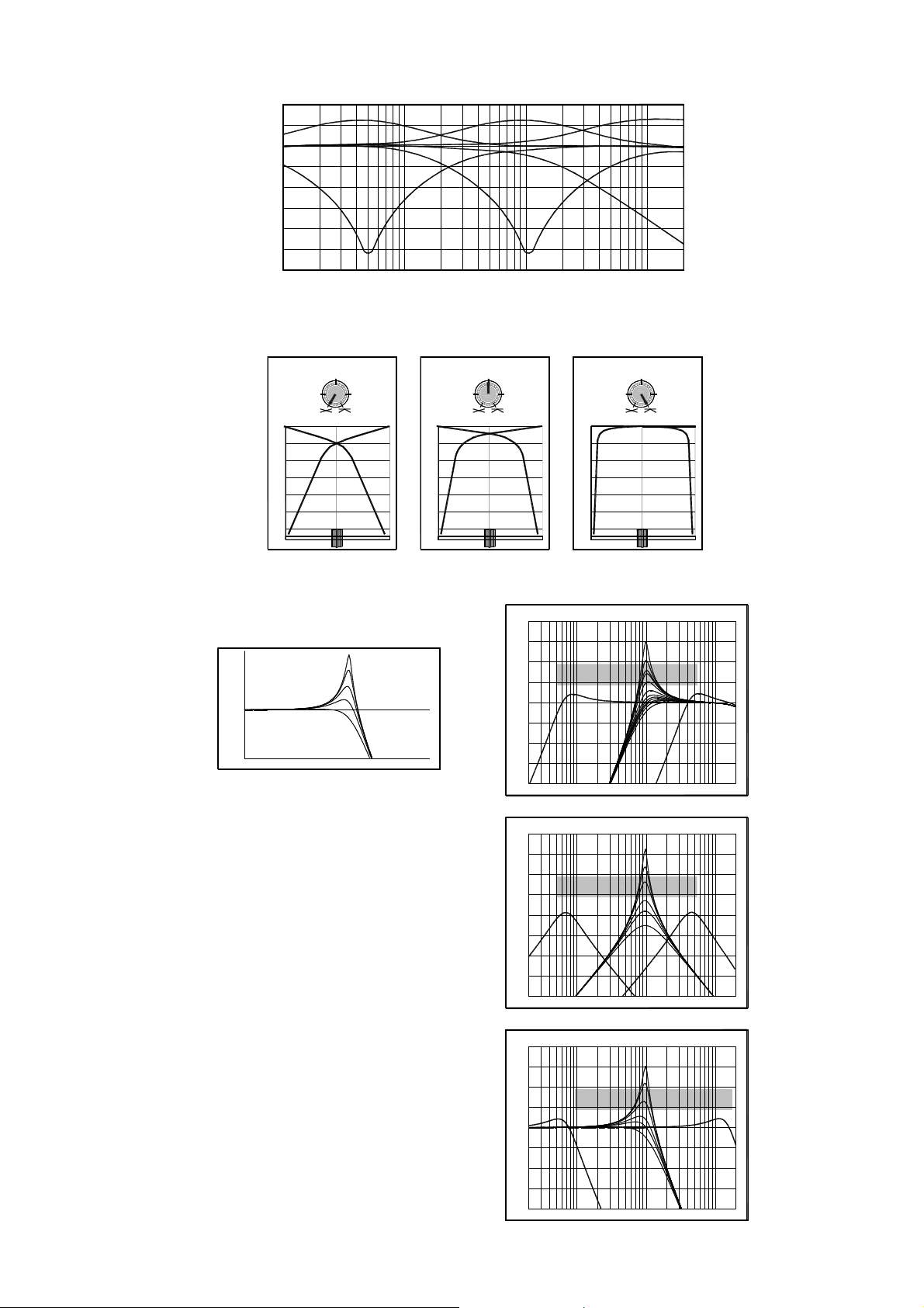
EQ Curves
+10
+5
0dB
-5
-10
-15
-20
-25
-30
10 100 1kHz 10k 20k
Crossfader Curves
+6dB BOOST
HIMIDLO
-26dB CUT
DIP
0dB
-6
-12
-18
-24
-30
-36
-6dB
VCF Curves
HI (WILD)
MID
LO (MILD)
0dB
RESONANCE
LO
FREQUENCY HI
CONSTANT POWER
0dB
-6
-12
-18
-24
-30
-36
-3dB 0dB
+20
+15
+10
+5
0dB
CUT
0dB
-6
-12
-18
-24
-30
-36
HI-PASS FILTER
LO
-5
-10
-15
-20
HI
10k20 1kHz100 20k
+20
+15
+10
+5
0dB
-5
-10
-15
-20
+20
+15
+10
+5
0dB
-5
-10
-15
-20
BAND-PASS FILTER
LO
LO-PASS FILTER
LO
HI
10k20 1kHz100 20k
HI
10k20 1kHz100 20k
6 XONE:32 Service Manual
Page 7
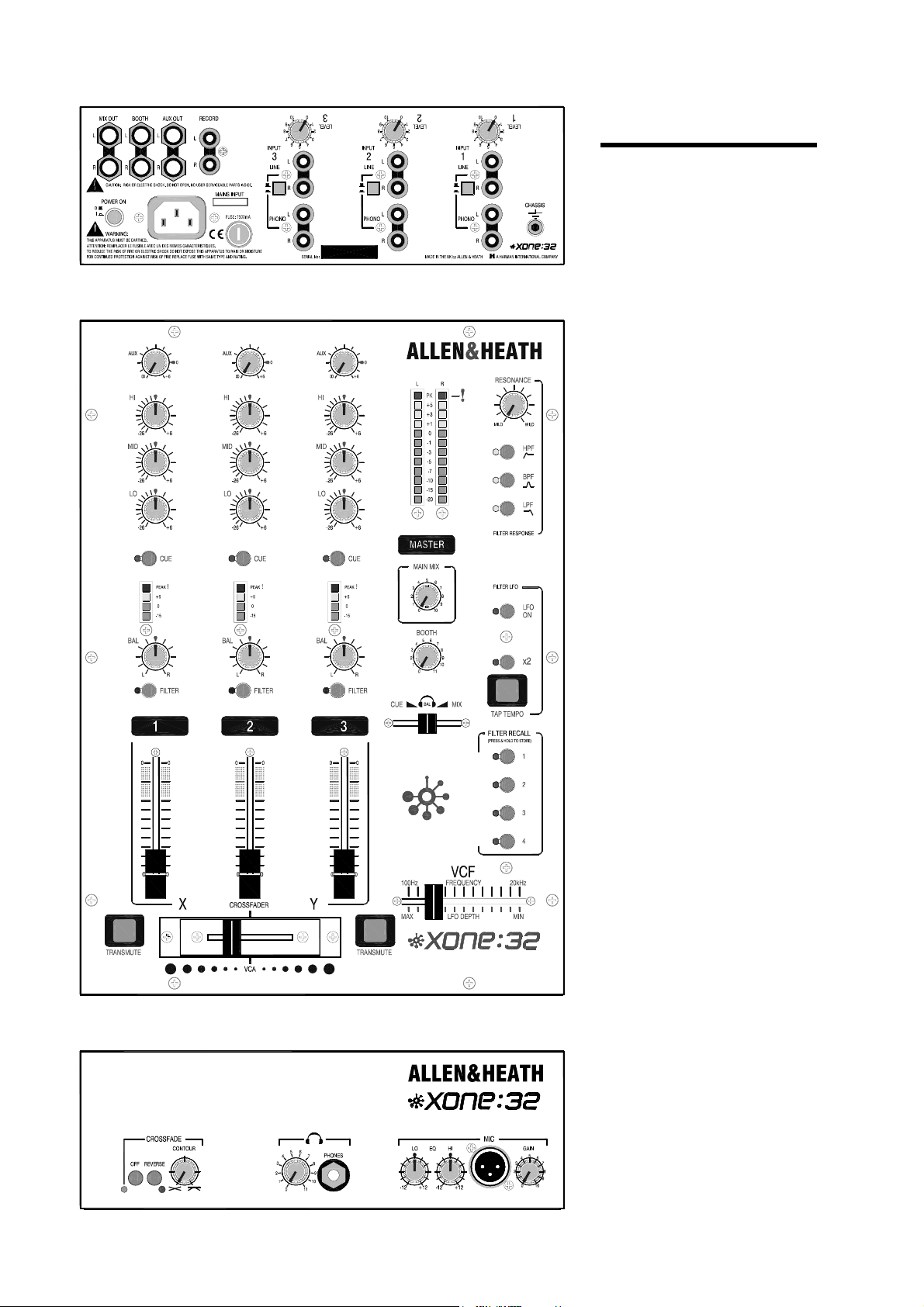
Front and Rear
Panel Layouts
AVIS: RISQUE DE CHOC ELECTRIQUE - NE PAS OUVRIR.
100 - 240V~
47-63Hz ~ 30W MAX
Welcome to the XONE:32
professional DJ mixer. This
stylish and solidly built 3 channel
club format console presents a
unique combination of
performance tools for the
professional DJ. Above all, it
features a sound quality second
to none. XONE:32 has been
designed and constructed using
the same rigorous standards we
apply to our large format
professional consoles used and
respected by top engineers and
performers throughout the world.
Please refer to the User Guide for
the operating instructions and
application notes.
DRS DIGITAL RECALL SYSTEM
P R O F E S S I O N A L D J M I X E R
P R O F E S S I O N A L D J M I X E R
XONE:32 Service Manual 7
Page 8
Specifications
0dBu = 0.775 Volts rms, +4dBu = 1.23V rms 0dBV = 1 Volt rms, -10dBV = 316mV rms
Max output level TRS +21dBu into >2k ohm
RCA +15dBu into >10k ohm
Headroom Channels +21dB
Mix to output +23dB
Freq response +0/-1dB 10Hz to 30kHz
Distortion < 0.02% THD+N @1kHz +10dBu
Crosstalk < 90dB Channel shutoff @1kHz
MIC EIN 22-22kHz -126dB 150 ohm source
Residual noise TRS -102dBu
RCA -92dBu
Mix noise TRS -87dB
Ch meters Peak reading 4 led
Main meters Peak reading 12 led
Power Supply
-15, 0, +5, +8 (PK)
-20 to +8 (PK)
Music EQ 3-Band +6/-26dB
100Hz, 1kHz, 10kHz
Mic EQ 2-Band +/-10dB
300Hz, 5kHz
HPF 60Hz
Ch fader 60mm stereo
Crossfader 45mm stereo VCA
Dual rail, gold contacts
Replaceable, P&G option
Filters Stereo analogue VCF
HPF, BPF, LPF types
100Hz to 20kHz sweep
LFO Finger tap tempo entry
Depth modulation of VCF
x2 Multiplier
Internal switch mode power unit with auto sensing mains input.
MAINS IN socket IEC 3 pin
Power lead Country dependent with moulded mains plug supplied
AC mains 100 to 240V AC @ 50/60Hz
Consumption 30W max
Mains fuse rating 100-240V AC T500mA 20mm
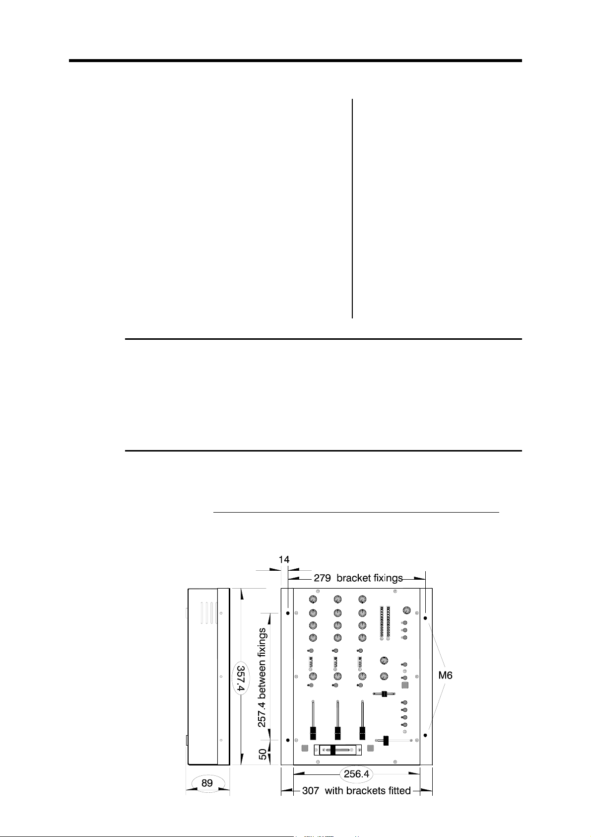
Dimensions and Weights
The console is fitted with rubber feet for desktop operation. An optional screw on rack ear kit is
available for rack or plinth mounting. This is fixed in place using M6 screws or bolts. Contact your
Allen & Heath agent for further information. The order code for the kit is: XONE:32-RK
Width Height Depth Weight
Desktop 257 mm (10.1”) 89 mm (3.5”) 358 mm (14.1”) 4 kg (9 lbs)
Rack ears fitted 307 mm (12.1”) 89 mm (3.5”) 358 mm (14.1”)
Packed 475 mm (18.7”) 210 mm (8.3”) 395 mm (15.6”) 5 kg (11 lbs)
8 XONE:32 Service Manual
Page 9

XONE:32
STEREO INPUTS
LINE
PHONO
LINE
PHONO
LINE
PHONO
CH1
L
R
L
R
CH2
L
R
L
R
CH3
L
R
L
R
SOURCE
RIAA
SOURCE
RIAA
SOURCE
RIAA
BLOCK DIAGRAM
LEVEL TRIM
3 BAND EQ
HI
MID
LO
LEVEL TRIM
3 BAND EQ
HI
MID
LO
LEVEL TRIM
3 BAND EQ
HI
MID
LO
GAIN
MIC
METER
METER
METER
HPF
FADER
FADER
FADER
2 BAND EQ
HI
LO
CUE
CUE
CUE
AUX
BALANCE
AUX
BALANCE
AUX
BALANCE
FREQUENCY
CUE MIX
AUX MIX
X VCA
DEPTH
TAP TEMPO
FREQ
L
R
RESONANCE
CROSSFADER
XY
CONTOUR
OFF
Y VCA
AUX
AUX SEND
REVERSE
ON
CUE MIX
CUE
CUE MAIN
LFO
VCF
FILTER
FILTER
FILTER
ON
X 2
HPF
BPF
LPF
L
AUX OUT
R
MAIN
L
R
USER PRESETS
1
2
3
4
LEVEL
MASTER
LEVEL
PRE-FADE
STORE AND RECALL THE FOLLOWING:
CH FILTER ON/OFF
FILTER TYPE
LFO ON/OFF
X 2 ON/OFF
BOOTH
MAIN
-10dBV
LEVEL
BAL
L
RECORD OUT
R
BOOTH OUT
MAIN OUT
PHONES
L
R
L
R
L
R
MAIN MIX
Connector Types
XLR connector : Pin 2 = hot (+) Pin 3 = cold (-) Pin 1 = GND
TRS input and output connectors : Tip = hot (+) Ring = cold (-) Sleeve = GND
RCA PHONO pin connectors
Input Connections Type Impedance Sensitivity
MIC IN Balanced XLR female 2k ohm -45 to –15dBu
Stereo LINE IN RCA phono >10k ohm -15 to +15dBu
Stereo PHONO IN RCA phono RIAA 47kohm/330pF 2 to 100mV
Output Connections Type Impedance Level
MIX OUT L,R Electronically balanced TRS jack <75 ohm 0dBu
BOOTH OUT L,R Impedance balanced TRS jack <75 ohm -2dBu
AUX OUT L,R Impedance balanced TRS jack <75 ohm -2dBu
RECORD OUT L,R RCA phono <600 ohm
-10dBV
HEADPHONES Tip = L Ring = R 30 to 600 ohm, 70 ohms recommended
XONE:32 Service Manual 9
Page 10

Installation
AVIS: RISQUE DE CHOC ELECTRIQUE - NE PAS OUVRIR.
Earthing
The connection to earth (ground) in an audio system is important for two reasons:
1. SAFETY - To protect the operator from high voltage electric shock, and
2. AUDIO PERFORMANCE - To minimise the effect of earth (ground)
loops which result in audible hum and buzz, and to shield the audio
signals from interference.
100 - 240V~
47-63Hz ~ 30W MAX
Connecting Mains Power Read the
SAFETY INSTRUCTIONS printed at the front
of this Service Manual and on the rear panel.
Check that the correct mains lead with
moulded plug has been supplied with your
console. The power supply accepts 50/60Hz
AC mains voltages within the range 100-240V
without changing any fuses or settings.
It is standard practice to turn connected power
amplifiers down or off before switching the
console on or off. This prevents any audible
switch-on thumps. Ensure that the IEC mains
plug is pressed fully into the rear panel socket
before switching on.
For safety it is important that all equipment earths are connected to mains earth so that exposed
metal parts are prevented from carrying high voltage which can injure or even kill the operator. It is
recommended that the system engineer check the continuity of the safety earth from all points in
the system including microphone bodies, turntable chassis, equipment cases, and so on.
The same earth is also used to shield audio cables from external interference such as the hum
fields associated with power transformers, lighting dimmer buzz, and computer radiation. Problems
arise when the signal sees more than one path to mains earth. An ‘earth loop’ (ground loop) results
causing current to flow between the different earth paths. This condition is usually detected as a
mains frequency audible hum or buzz.
To ensure safe and trouble-free operation we recommend the following:
• Have your mains system checked by a qualified electrician If the supply earthing is solid to
start with you are less likely to experience problems.
• Do not remove the earth connection from the console mains plug The console chassis is
connected to mains earth through the power cable to ensure your safety. Audio 0V is
connected to the console chassis internally. If problems are encountered with earth loops
operate the audio ‘ground lift’ switches on connected equipment accordingly, or disconnect the
cable screens at one end, usually at the destination.
• Make sure that turntables are correctly earthed A chassis earth terminal is provided on the
console rear panel to connect to turntable earth straps.
• Deal with ground loops Should you experience hum or buzz caused by ground loops, check
first that each piece of equipment has its own separate path to ground. If so, operate ground lift
switches on connected equipment in accordance with the instruction manuals. Alternatively
disconnect the cable screen at the destination end only. This breaks the offending loop while
still maintaining the signal shielding down the length of the cable.
• Use low impedance sources such as microphones and line level equipment rated at 200
ohms or less to reduce susceptibility to interference. The console outputs are designed to
operate at very low impedance to minimise interference problems.
• Use balanced connections for the microphone and main outputs as these provide further
immunity by cancelling out interference that may be picked up on long cable runs. Refer to the
cable drawing for information on how to connect balanced and unbalanced equipment.
• Route cables to avoid interference To avoid interference pickup keep audio cables away
from mains power units and cables, thyristor dimmer units or computer equipment. Where this
cannot be avoided, cross the cables at right angles to minimise interference.
• Use good quality cables and connectors and check for correct wiring and reliable solder
joints. Allow sufficient cable loop to prevent damage through stretching.
10 XONE:32 Service Manual
Page 11

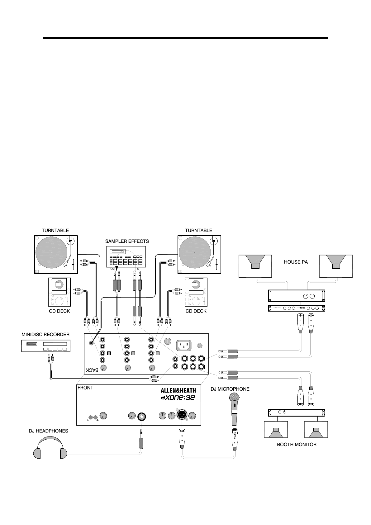
Cables and Connections
The XONE:32 uses professional grade 3 pin XLR, 1/4" TRS jack and RCA PHONO sockets. The
following mating plugs may be used:
The microphone input XLR connector is 3 wire balanced. This has 3 connector pins: Pin 1 =
ground (screen), Pin 2 = signal hot (+), Pin 3 = signal cold (-). The jack sockets are the 3 pole TRS
type. These are wired to work with either the balanced TRS or the unbalanced 2 pole TS type
plugs without cable modification. The sockets have 3 connector pins: Inputs and outputs are Tip =
signal hot (+), Ring = signal cold (-), Sleeve = ground (screen). Headphones are Tip = left, Ring =
right, Sleeve = ground. The RCA phono connectors are 2 wire unbalanced to connect to
equipment such as CD players, turntables and domestic amplifiers.
To ensure best performance, we recommend that you use high quality audio cables and
connectors, and take time to check for reliable and accurate cable assembly. It is well known that
many audio system failures are due to faulty interconnecting leads. Avoid reversing + and - on
balanced connections as this will result in reverse polarity connections which may cause signal
cancellation effects. Refer to the cable diagram for how to wire unbalanced to balanced
connections. It is fine to use a Y-adapter to feed one output to several inputs, but never use a
Y-adapter to sum two outputs into one input.
XONE:32 Service Manual 11
Page 12

Gain and Operating Levels
From the User Guide:
It is most important that the system gain and level settings are correctly set. It is well known that
many DJs push the gain to maximum with meters peaking hard in the belief that they are getting the
best from the system. THIS IS NOT THE CASE ! The best can only be achieved if the system
levels are set within the normal operating range and not allowed to peak. Peaking simply results in
signal distortion, not more volume. It is the specification of the amplifier / speaker system that sets
the maximum volume that can be achieved, not the console. The human ear too can fool the
operator into believing that more volume is needed. Be careful as this is in fact a warning that
hearing damage will result if high listening levels are maintained. Remember that it is the QUALITY
of the sound that pleases the ear, not the VOLUME.
Use the LEVEL TRIM to match the input source to the normal operating level of the console.
Adjust this so that the CHANNEL METER averages 0dB with loudest moments reading +5. Press
the CUE SWITCH to listen to the signal on headphones. Adjust the CHANNEL FADER and
MASTER LEVEL so that they normally operate in the near the top of travel. Make sure the
amplifier/speaker system has been correctly calibrated for the loudest volume required at the fader
top position. Boosting the EQ also adds gain to the system. Reduce by turning back the LEVEL
TRIM if the meter red peak LEDs flash. Adjust the HEADPHONES and BOOTH monitor controls
for safe listening levels.
The diagram illustrates the operating range of the audio signal.
NORMAL OPERATING RANGE. For normal music the signal should range between –5 and +5
on the meters with average around 0dB. This allows enough HEADROOM for unexpected peaks
before the signal hits its maximum CLIPPING voltage and distorts. It also achieves the best
SIGNAL-TO-NOISE-RATIO by keeping the signal well above the residual NOISE FLOOR (system
hiss). The DYNAMIC RANGE is the maximum signal swing available between the residual noise
floor and clipping. The XONE:32 provides a massive 108dB dynamic range.
A final note … The human ear is a remarkable organ with the ability to compress or ‘shut down’
when sound levels become too high. Do not interprete this natural response as a reason to turn the
system volume up further ! As the session wears on ear fatigue may set in, and the speaker cones
may become hot so reducing the effectiveness of the system and listeners to gain any benefit from
increased volume.
BE SENSIBLE, BE SAFE WITH SOUND LEVELS
12 XONE:32 Service Manual
Page 13

Order Codes
The following products and parts can be ordered from Allen & Heath or the approved dealer:
XONE:32/v XONE:32 3 stereo channel mixer /v = specify voltage
XONE2:62/v XONE:62 6 stereo channel mixer /v = specify voltage
XONE2:464/v XONE:464 4 mic 6 stereo channel mixer /v = specify voltage
002-684 60mm Stereo Channel Fader for XONE:32, 62 & 464
002-719 Optional P&G crossfader for XONE:32, 62 & 464
002-720 Standard crossfader for XONE:32
002-722 30mm Cue/Mix fader for XONE:32
002-723 60mm VCF/LFO depth fader for XONE:32
XONE:32-RK Plinth mounting rack ear kit
AP4264 XONE:32 User Guide
AP4265 XONE:32 Service Manual
Replacing the Crossfader
The crossfader on a DJ mixer is heavily used and can suffer considerable wear and tear. The
audio design using VCAs prevents clicks and scratchiness as the fader wears. However, the
movement can become mechanically stiff or sloppy in time, or become ingrained with dirt. Should
this be the case the fader may need replacement. The XONE:32 crossfader is removable and can
easily be replaced in a few minutes. There are two versions available, the standard type and the
higher grade Penny & Giles type. Make sure you order the correct version from Allen & Heath.
Use a medium size cross-point (Pozidriv) screwdriver to undo and remove the two outer screws on
the crossfader plate. Do not remove the inner screws. Lift the crossfader assembly up and away
from the console panel. Unplug the cable from the old crossfader and plug in the new assembly.
Check that the connector is correctly aligned and pushed on. Replace the assembly making sure
the cable faces the left side of the console. Refit the screws and test operation.
XONE:32 Service Manual 13
Page 14

Tips and Troubleshooting As printed in the User Guide
For your safety do not remove the EARTH
(ground) connection in the power lead of the
console or connected equipment.
☺ Have your MAINS SYSTEM checked by a
qualified electrician. If the earthing is solid to start
with you are less likely to experience problems.
☺ Use high grade AUDIO CABLES and check
them for reliable connection. It is well known that
many audio system problems are due to faulty
cables and connectors.
In a club or similar installation strict SOUND
LEVEL and noise regulations may apply. Check
that your system levels are correctly set up to
comply.
To avoid damage to your hearing start with
the HEADPHONES level control at minimum and
turn up only as much as is needed to maintain
comfortable listening level. Do not drive
headphones at high listening levels for long periods
of time.
Always switch connected AMPLIFIERS on
last and off first to avoid thumps when the console
and connected equipment is turned on or off.
Reduce gain if the red meter PEAK led
flashes. These warn you that you are near clipping
which may result in system overload and distortion.
The XONE:32 provides plenty of drive and
headroom when operated around the 0 to +5 meter
points. Check that the amplifier / speaker system is
correctly matched and set up for correct levels.
Increasing VCF RESONANCE boosts a
narrow band of selected frequencies. Make sure
you reduce the channel gain if the red peak meters
start to flash. It is best to start experimenting with
this control set to minimum.
☺ If you suspect a console fault. The console is
the heart of the audio system and is often
suspected faulty when a problem occurs. Usually
the fault is found to be with other equipment in the
system, typically the interconnecting leads, input
sources, or level matching between equipment.
Check for source problems by unplugging each
channel in turn listening for a change in symptom.
To check the console, isolate it by unplugging all
sources and outputs leaving just headphones and a
reference source such as a CD player connected.
? I have plugged in a microphone but it does
not work. The XONE:32 is designed to operate
with non-phantom powered dynamic microphones
such as the popular vocal types. Do not use
microphones which require phantom power. If it
has an on/off switch check that it is turned on.
Make sure the front panel GAIN control is turned
up.
? The signal sounds very distorted with high
level and excessive bass. Only plug turntables
needing RIAA equalisation into the PHONO inputs.
Other equipment should be plugged into the LINE
inputs.
? There is a hum on the turntable channels.
Check that the turntable earth strap has been
correctly connected to the console chassis earth
post. Also check that the turntable headshell and
cartridge are correctly aligned and plugged in.
? The output meter reads fine but the signal is
distorted. Check the channel meter to make sure
it is not peaking red. If it is, the output meter may
still read fine if the fader or master level control is
not set fully up. Reduce the input level trim if the
channel meter reads too high.
? Only one side of the stereo mix is working.
Check that the BAL control is not set fully to either L
or R. Also check for bad connections, in particular
RCA phono leads and turntable headshell and
cartridge pins.
? There is feedback. Check that the microphone
is not placed next to the headphones or
loudspeakers. The mic may pick up its own signal
and feed back. In loud listening conditions
feedback can sometimes be caused by mechanical
vibration through the turntables into the cartridge, or
even the needle resting on a cued turntable starting
to resonate in the groove of the record.
? When the VCF is switched on there is very
little sound. Operate the VCF frequency slider to
restore the frequency content of the sound.
? The LED is flashing but the LFO is not
working. Check that the LFO is turned on and its
LED is green, flashing red to indicate speed. The
LED always flashes red whether it is on or off.
? I tap in the tempo but the LED flashes too
fast. The x2 has been switched on.
? There is no cue signal. Check that the
CUE/MIX slider is not set fully right for mix only.
? There is no channel signal. Check that the rear
panel input selector switch is correctly set.
? The crossfader is not working. Make sure the
crossfader is turned on and its front panel green
LED lit.
? The crossfader works backwards. Check that
the reverse switch has not been pressed and its red
LED on. If it is off then check that the crossfader
has been re-fitted the right way round if previously
removed.
? I have connected a stereo source to a single
input using a Y-adapter but it sounds bad. Do
not connect more than one output to the input.
These adapters are designed to feed one output to
two inputs, not the other way round.
? The switch settings are different when I
switch the console on. The settings always
return to default on power up. You can store
preferred settings in the user presets and select one
of these after power up.
14 XONE:32 Service Manual
Page 15

Page 16

Page 17

Page 18

Page 19

Page 20

Page 21

Page 22

Page 23

Page 24

Page 25

Page 26

 Loading...