

Allegro UGS3060KA, UGS3059KA, UGN3060KA, UGN3059KA Datasheet
3059
AND
3060
HALL-EFFECT
GEAR-TOOTH SENSORS
—AC COUPLED
X X
V
CC
1 432 5
FILTER
OUTPUT
SUPPLY
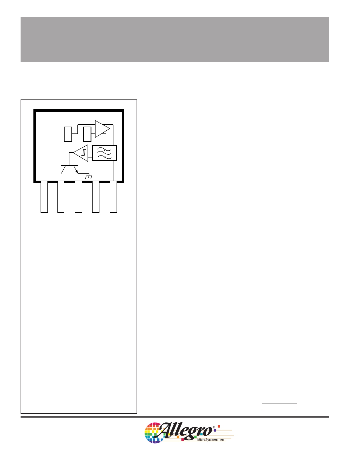
Pinning is shown viewed from branded side.
GROUND
FILTER
Dwg. PH-011
3059
AND
3060
HALL-EFFECT GEAR-TOOTH SENSORS
—AC COUPLED
The UGN/UGS3059KA and UGN/UGS3060KA ac-coupled Halleffect gear-tooth sensors are monolithic integrated circuits that switch
in response to changing differential magnetic fields created by moving
ferrous targets. These devices are ideal for use in non-zero-speed,
gear-tooth-based speed, position, and timing applications such as in
anti-lock braking systems, transmissions, and crankshafts.
Both devices, when coupled with a back-biasing magnet, can be
configured to turn ON or OFF with the leading or trailing edge of a
gear-tooth or slot. Changes in fields on the magnet face caused by a
moving ferrous mass are sensed by two integrated Hall transducers
and are differentially amplified by on-chip electronics. This differential
sensing design provides immunity to radial vibration within the devices’
operating air gaps. Steady-state magnet and system offsets are
eliminated using an on-chip differential band-pass filter. This filter also
provides relative immunity to interference from RF and electromagnetic sources. The on-chip temperature compensation and Schmitt
trigger circuitry minimizes shifts in effective working air gaps and
switch points over temperature, allowing operation to low frequencies
over a wide range of air gaps and temperatures.
Each Hall-effect digital Integrated circuit includes a voltage regulator, two quadratic Hall-effect sensing elements, temperature compensating circuitry, a low-level amplifier, band-pass filter, Schmitt
trigger, and an open-collector output driver. The on-board regulator
permits operation with supply voltages of 4.5 to 24 volts. The output
stage can easily switch 20 mA over the full frequency response range
of the sensor and is compatible with bipolar and MOS logic circuits.
Data Sheet
27612.20*
ABSOLUTE MAXIMUM RATINGS
at T
= +25°C
A
Supply Voltage, VCC............................. 24 V
Reverse Battery Voltage, V
Magnetic Flux Density, B............ Unlimited
Output OFF Voltage, V
Output Current, I
Package Power Dissipation,
P
............................................ 500 mW
D
Operating Temperature Range, T
Prefix ‘UGN’................. -20°C to +85°C
Prefix ‘UGS’ ............... -40
Storage Temperature Range,
T
............................... -65°C to +150°C
S
OUT
......................... 25 mA
OUT
.......... -30 V
RCC
.................... 24 V
A
°C to +125°C
The two devices provide a choice of operating temperature
ranges. Both devices are packaged in a 5-pin plastic SIP.
FEATURES
■ Senses Motion of Ferrous
Targets Such as Gears
■ Wide Operating Temperature Range
■ Operation to 30 kHz
■ Resistant to RFI, EMI
Always order by complete part number, e.g., UGS3060KA .
■ Large Effective Air Gap
■ 4.5 V to 24 V Operation
■ Output Compatible With
All Logic Families
■ Reverse Battery Protection
■ Resistant to Physical Stress
3059
AND
3060
HALL-EFFECT
GEAR-TOOTH SENSORS
—AC COUPLED
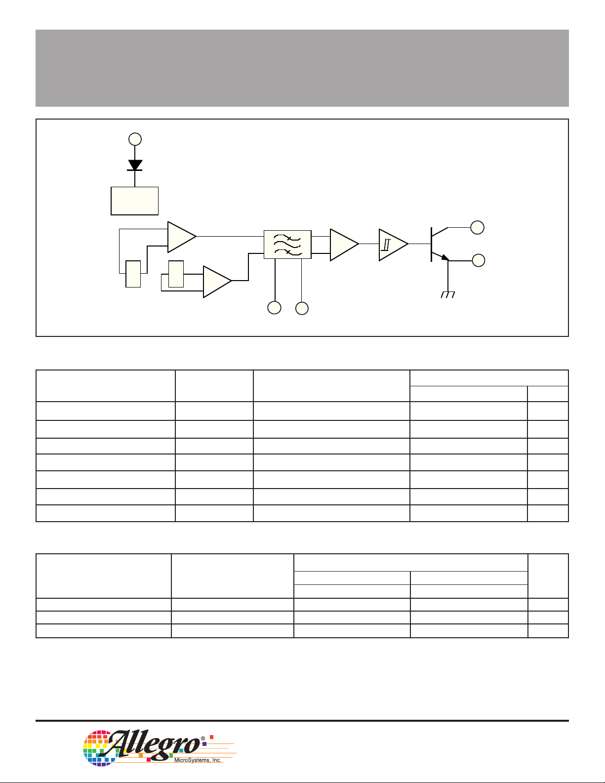
1
SUPPLY
FUNCTIONAL BLOCK DIAGRAM
REG
OUTPUT
2
+
-
3
X X
4
FILTER
5
FILTER
GROUND
Dwg. FH-008
ELECTRICAL CHARACTERISTICS over operating temperature range.
Limits
Characteristic Symbol Test Conditions Min. Typ. Max. Units
Supply Voltage V
Output Saturation Voltage V
Output Leakage Current I
Supply Current I
High-Frequency Cutoff f
Output Rise time t
Output Fall time t
OUT(SAT)
CC
OFF
CC
coh
r
f
Operating 4.5 — 24 V
I
= 20 mA, B > B
OUT
V
= 24 V, B < B
OUT
VCC = 18 V, B < B
-3 dB 30 — — kHz
V
= 12 V, RL = 820 Ω — 0.04 0.2 µs
OUT
V
= 12 V, RL = 820 Ω — 0.18 0.3 µs
OUT
OP
RP
RP
— 130 400 mV
——10µA
—1120mA
MAGNETIC CHARACTERISTICS over operating temperature and supply voltage ranges
Part Numbers*
3059 3060
Characteristic Test Conditions Min. Typ. Max. Min. Typ. Max. Units
Operate Point, B
Release Point, B
Hysteresis, B
NOTES: * Complete part number includes a prefix to identify operating temperature range (UGN or UGS) and the package suffix KA.
Magnetic switch points are specified as the difference in magnetic fields at the two Hall elements.
As used here, negative flux densities are defined as less than zero (algebraic convention).
Typical values are at TA = 25°C and VCC = 12 V.
OP
RP
hys
Output switches OFF to ON 10 65 100 5.0 15 35 G
Output switches ON to OFF -100 -65 -10 -35 -15 -5.0 G
BOP - B
RP
115 Northeast Cutoff, Box 15036
Worcester, Massachusetts 01615-0036 (508) 853-5000
Copyright © 1993, 1995 Allegro MicroSystems, Inc.
— 130 — — 30 — G
3059
AND
3060
HALL-EFFECT
GEAR-TOOTH SENSORS
—AC COUPLED
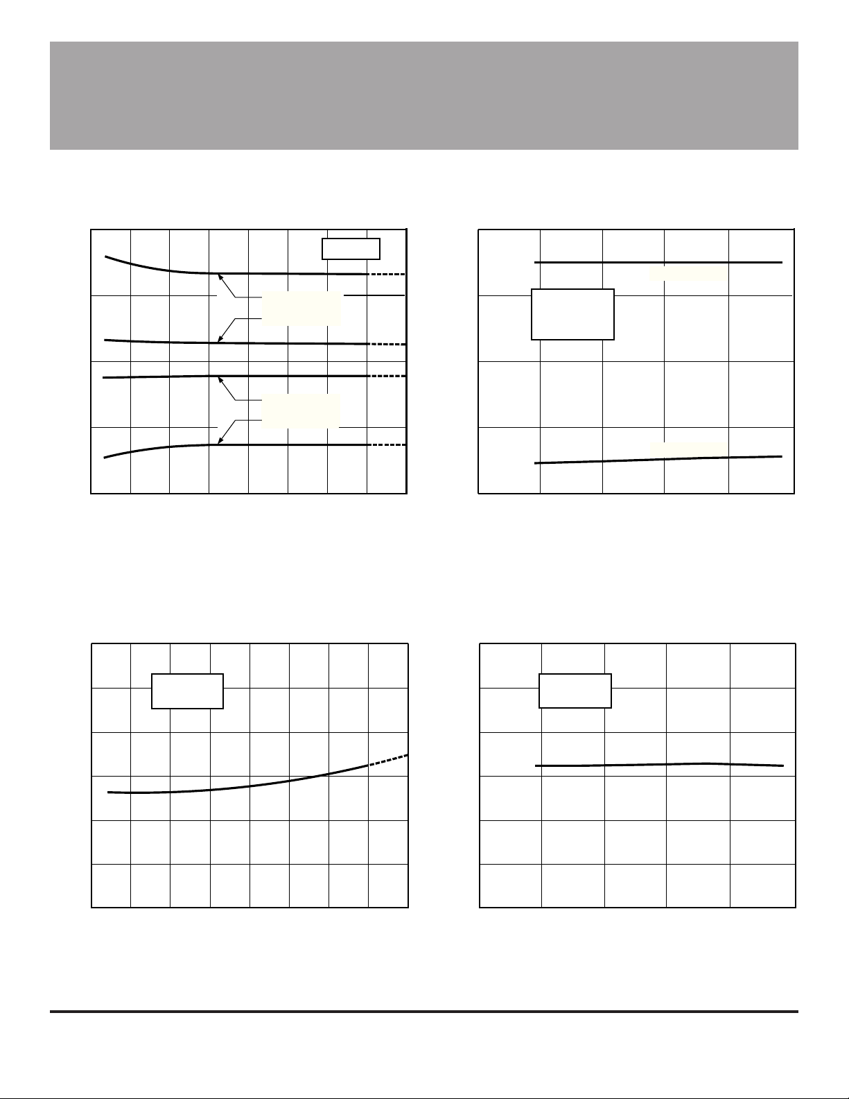
TYPICAL OPERATING CHARACTERISTICS
SWITCH POINTS
100
50
0
-50
DIFFERENTIAL FLUX DENSITY IN GAUSS
-100
-50
-25 25 75 125
0 50 100
AMBIENT TEMPERATURE IN °C
3059
OPERATE POINT
3060
3060
RELEASE POINT
3059
OUTPUT SATURATION VOLTAGE
V = 8 V
CC
Dwg. GH-056
150
20
10
0
-10
DIFFERENTIAL FLUX DENSITY IN GAUSS
-20
0
UGN/UGS3060KA
I = 20 mA
OUT
T = +25°C
A
510152025
SUPPLY VOLTAGE IN VOLTS
OPERATE POINT
RELEASE POINT
Dwg. GH-057
300
I = 20 mA
OUT
V = 12 V
CC
200
100
SATURATION VOLTAGE IN mV
0
-50
0 25 50 75 100
AMBIENT TEMPERATURE IN °C
150-25 125
Dwg. GH-029-1
200
I = 20 mA
OUT
T = +25°C
A
150
100
SATURATION VOLTAGE IN mV
50
0
510152025
SUPPLY VOLTAGE IN VOLTS
Dwg. GH-055
 Loading...