

Allegro UGQ5140K Datasheet
5140
PROTECTED POWERHALL
®
SENSOR:
LAMP/SOLENOID DRIVER
5140
Data Sheet
27695*
X
V
CC
1
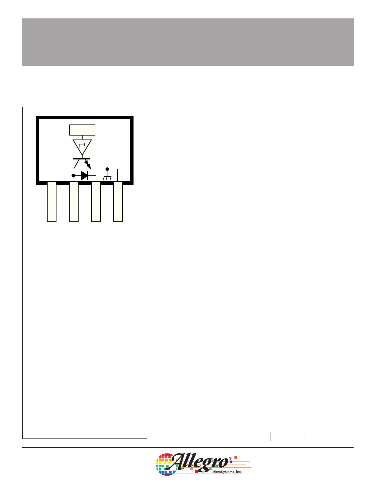
Pinning is shown viewed from branded side.
234
SUPPLY
OUTPUT
DIODE
GROUND
Dwg. PH-001
ABSOLUTE MAXIMUM RATINGS
at T
= +25°C
A
PROTECTED POWERHALL
®
SENSOR
— LAMP/SOLENOID DRIVER
The UGQ5140K unipolar Hall effect switch is a monolithic
integrated circuit designed for magnetic actuation of low-power
incandescent lamps or inductive loads such as relays or solenoids.
Included on chip is a Darlington power output that is capable of continuously sinking in excess of 300 mA. Internal protection circuitry
limits surge (lamp turn-ON) or fault currents to approximately 900 mA.
A sensitive magnetic threshold allows the device to be used in conjunction with inexpensive magnets or in applications that require
relatively large operating distances.
Each sensor/driver includes a magnetic sensing Hall voltage
generator, operational amplifier, Schmitt trigger, voltage regulator, and
an open-collector, high-gain Darlington power output stage. The
regulator allows use of the device with supply voltages of 4.5 V to
28 V. On-chip compensation circuitry stabilizes switch-point performance over temperature. The magnetic operation of this device is
similar to that of the A3141E— Hall-effect switch.
The sensitive magnetic switch point coupled with the power output,
current limiting, and thermal limiting circuitry allow the UGQ5140K to
magnetically actuate various loads without requiring any external
components.
The UGQ5140K is rated for operation over an extended temperature range of -40°C to +85°C. It is supplied in a four-pin mini-SIP
plastic package, 0.200" (5.08 mm) wide, 0.130" (3.30 mm) high, and
0.060" (1.54 mm) thick.
Supply Voltage, VCC . . . . . . . . . . . . . . 28 V
Reverse Battery Voltage, V
Output OFF Voltage, V
Over-Current Protected Output Voltage,
V
. . . . . . . . . . . . . . . . . . . . . . . . 25 V
OUT
Output ON Current, I
Magnetic Flux Density, B . . . . . . Unlimited
Package Power Dissipation,
P
.. . . . . . . . . . . . . . . . . . . See Graph
D
Operating Temperature Range,
T
. . . . . . . . . . . . . . . . . -40°C to +85°C
A
Storage Temperature Range,
T
. . . . . . . . . . . . . . . . -65°C to +150°C
S
* Output is current limited at approximately 900
mA and junction temperature limited if current in
excess of 900 mA is attempted. See Circuit
Description and Applications for further
information.
OUT
OUT
. . . . . -45 V
RCC
. . . . . . . . . . 45 V
. . . . . . . 900 mA*
FEATURES
■ Magnetically Actuated Power Switch
■ Temperature-Compensated Switch Points
■ High Current-Sink Capability
300 mA Continuous
900 mA Peak Current Limit
■ Output Short-Circuit Protection
■ Low Quiescent Standby Current
■ Linear Thermal Limiting
■ Automotive Temperature Range
-40°C to +85°C, Operating
■ Internal Inductive Flyback/Clamp Diode Protection
■ Reverse Battery Protection
■ Low-Profile 4-Pin Mini-SIP
Always order by complete part number: UGQ5140K .
5140
ALLOWABLE PACKAGE POWER DISSIPATION IN WATTS
1
3
2
4
PROTECTED POWERHALL
®
SENSOR:
LAMP/SOLENOID DRIVER
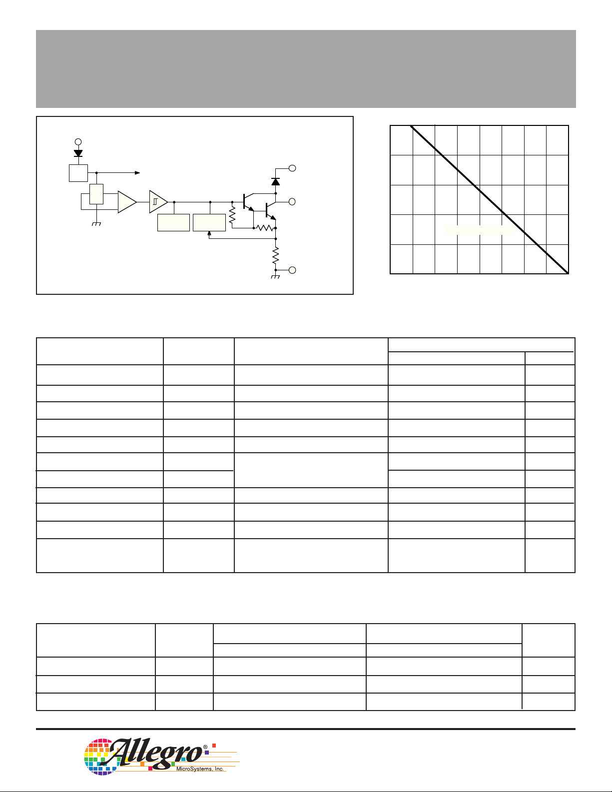
FUNCTIONAL BLOCK DIAGRAM
V
CC
REV. BATTERY
PROTECTION
REG.
X
THERMAL
LIMIT
CURRENT
LIMIT
ELECTRICAL CHARACTERISTICS at T
DIODE
OUTPUT
<<1Ω
GROUND
Dwg. FH-001
= -40°C to +85°C, V
A
1.0
0.8
0.6
0.4
0.2
0
-50
= 4.5 V to 24 V
CC
FREE AIR, R = 177°C/W
θJA
25
0-25
AMBIENT TEMPERATURE IN °C
50 75 100 125 150
(unless otherwise noted).
Limits
Characteristic Symbol Test Conditions Min. Typ. Max. Units
Supply Voltage Range V
Output Leakage Current I
Output Sustaining Voltage V
Output Saturation Voltage V
OUT(SUS)
OUT(SAT)
Over-Current Limit I
Output Rise Time t
Output Fall Time t
Supply Current I
Diode Forward Voltage V
Diode Leakage Current I
Thermal Limit T
CC
OUT
LIMIT
r
f
CC
F
R
LIMIT
Operating 4.5 12 24 V
V
= 24 V — <1.0 10 µA
OUT
I
= 100 mA 35 — — V
OUT
I
= 300 mA, VCC = 24 V — 0.84 1.2 V
OUT
VCC = V
= 12 V, B ≥ 500 G — 900 — mA
OUT
VCC = 12 V, VBB = 18 V, — 0.04 2.0 µs
RL = 1.1 kΩ, CL = 20 pF — 0.04 2.0 µs
Output OFF — 5.5 10 mA
IF = 300 mA — 1.1 1.5 V
VR = 35 V — <1.0 50 µA
VCC = V
I
OUT
= 12 V, B ≥ 500 G,
OUT
= 10 mA — 165 — °C
Dwg. GH-001
Typical Data is at TA = +25°C and is for design information only.
MAGNETIC CHARACTERISTICS at VCC = 4.5 V to 24 V.
Characteristic Symbol Min. Typ. Max. Min. Typ. Max. Units
Magnetic Operate Point B
Magnetic Release point B
Hysteresis B
OP
RP
hys
TA = +25°CT
= -40°C to +85°C
A
70 155 200 45 — 240 G
50 100 180 25 — 220 G
20 55 — 20 — — G
115 Northeast Cutoff, Box 15036
Worcester, Massachusetts 01615-0036 (508) 853-5000
W
Copyright © 1991, 1995 Allegro MicroSystems, Inc.
5140
PROTECTED POWERHALL
®
SENSOR:
LAMP/SOLENOID DRIVER
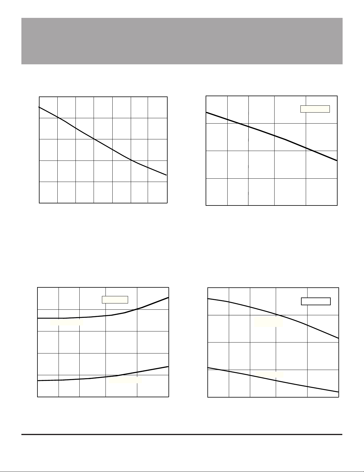
TYPICAL OPERATING CHARACTERISTICS
1000
950
900
850
PEAK CURRENT LIMIT IN mA
800
750
-20-40
0
AMBIENT TEMPERATURE IN °C
25 85 105 125
55
Dwg. GH-004
1.0
0.9
0.8
0.7
SATURATION VOLTAGE IN VOLTS
0.6
-40
-20 0 25 55
AMBIENT TEMPERATURE IN °C
I = 300 mA
OUT
Dwg. GH-002A
85
180
160
OPERATE POINT
140
120
SWITCH POINT IN GAUSS
100
80
-40
-20 0 25 55
AMBIENT TEMPERATURE IN °C
I = 10 mA
OUT
RELEASE POINT
85
Dwg. GH-006A
9.0
8.0
7.0
6.0
SUPPLY CURRENT IN mA
5.0
-40
-20 0 25 55
AMBIENT TEMPERATURE IN °C
OUTPUT ON
I = 10 mA
OUT
OUTPUT OFF
V = 12 V
CC
85
Dwg. GH-003A
 Loading...