

Allegro A3421EKA, A3422LKA-TL, A3422LKA, A3422EKA-TL, A3422EKA Datasheet
...
The A3421xKA and A3422xKA Hall-effect, direction-detection
sensors are a new generation of special-function integrated sensors that
are capable of sensing the direction of rotation of a ring magnet. These
transducers provide separate digital outputs that provide information on
magnet rotation speed, direction, and magnet pole count. These devices
eliminate the major manufacturing hurdles encountered in fine-pitch
direction-detection applications, namely maintaining accurate mechanical location between the two active Hall elements. Here, the two Hall
elements are photolithographically aligned to better than 1 µm, as
contrasted with 100 µm or worse mechanical location tolerance when
manufactured discretely. These highly sensitive, temperature-stable,
magnetic transducers are ideal for use in digital-encoder systems in the
harsh environments of automotive or industrial applications. The
A3421xKA is a high-hysteresis device designed for low-resolution
pulse counting while the A3422xKA is a high-sensitivity device
optimized for use with high-density magnets.
The A3421xKA and A3422xKA monolithic integrated circuits
contain two independent Hall-effect latches whose digital outputs are
internally coupled to CMOS logic circuitry that decodes signal speed
and direction. Extremely low-drift BiCMOS circuitry is used for the
amplifiers to ensure symmetry between the two latches so that signal
quadrature can be maintained. An on-chip voltage regulator allows the
use of these devices from a 4.5 V to 18 V supply. Both devices have
standard open-collector outputs; the logic operation of both devices is
the same.
Two operating temperature ranges are provided; suffix ‘E–’ is for
the automotive and industrial temperature range of -40°C to +85°C,
suffix ‘L–’ is for the automotive and military temperature range of
-40°C to +150°C. The 5-pin ‘KA’ SIP package provides a cost-competitive solution to linear magnetic sensing in harsh environments.
FEATURES
■ Internal Direction-Decoding Circuitry
■ Two Matched Hall Latches On A Single Substrate
■ Superior Temperature Stability
■ 4.5 V to 18 V Operation
Electrically Defined Power-On State
Under-Voltage Lockout
HALL-EFFECT,
DIRECTION-DETECTION SENSORS
Always order by complete part number, e.g., A3421EKA .
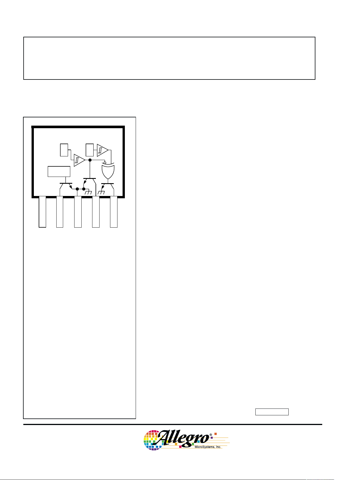
X
V
CC
1 432 5
Dwg. PH-015
SUPPLY
DIRECTION
GROUND
E1 OUTPUT
SPEED
LOGIC
X
E1 E2
Pinning is shown viewed from branded side.
ABSOLUTE MAXIMUM RATINGS
Supply Voltage, VCC. . . . . . . . . . . . . 18 V
Magnetic Flux Density, B . . . . Unlimited
Output OFF Voltage, V
OUT
. . . . . . . . V
CC
Output Sink Current, I
OUT
. . . . . . . 30 mA
Package Power Dissipation,
PD. . . . . . . . . . . . . . . . . . . . . . 500 mW
Operating Temperature Range, T
A
Suffix ‘EKA’ . . . . . . . -40˚C to +85˚C
Suffix ‘LKA’ . . . . . . -40˚C to +150˚C
Storage Temperature Range,
TS. . . . . . . . . . . . . . . -65˚C to +170˚C
3421
AND
3422
PRELIMINARY INFORMATION
(subject to change without notice)
September 6, 2000
Data Sheet
27650.1
3421
AND
3422
HALL-EFFECT,
DIRECTION-DETECTION
SENSORS
115 Northeast Cutoff, Box 15036
Worcester, Massachusetts 01615-0036 (508) 853-5000
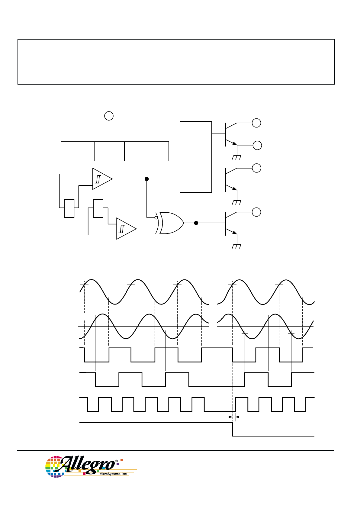
FUNCTIONAL BLOCK DIAGRAM
TIMING DIAGRAM
B
OP1
B
RP1
Dwg. WH-012A
0
+B
-B
0
+B
-B
B
RP2
OUT
E1
OUT
E2
(INTERNAL)
SPEED
(OUT
E1
XOR OUTE2)
B
OP2
DIRECTION
CHANGE IN DIRECTION
t
d
SPEED
4
DIRECTION2
E1 OUTPUT
1
X X
Dwg. FH-018
GROUND
5
3
LOGIC
E1
E2
SUPPLY
POWER-ON
LOGIC
REG
UVLO
Copyright © 1999 Allegro MicroSystems, Inc.
3421
AND
3422
HALL-EFFECT,
DIRECTION-DETECTION
SENSORS
www.allegromicro.com
Limits
Characteristic Symbol Test Conditions Min. Typ. Max. Units
Supply Voltage Range V
CC
Operating, TJ < 165°C
1
4.5 — 18 V
Output Leakage Current I
OFF
V
OUT
= VCC = 18 V — <1.0 10 µA
Output Saturation Voltage V
OUT(SAT)IOUT
= 20 mA — 0.21 0.50 V
Power-On State POS VCC = 0 → 5 V, OFF OFF OFF —
B
RP1
< B < B
OP1
, B
RP2
< B < B
OP2
Under-Voltage Lockout V
CC(UV)IOUT
= 20 mA, VCC = 0 → 5 V — 3.5 — V
Under-Voltage Hysteresis V
CC(hys)
Lockout (V
CC(UV)
) - Shutdown — 0.5 — V
Power-On Time t
po
VCC > 4.5 V — — 50 µs
Output Rise Time t
r
CL = 20 pF, RL = 820 Ω — 200 — ns
Output Fall Time t
f
CL = 20 pF, RL = 820 Ω — 200 — ns
Direction Change Delay t
d
CL = 20 pF, RL = 820 Ω 0.5 1.0 5.0 µs
Supply Current I
CC
VCC = 8 V, All outputs OFF 5.0 9.0 18 mA
ELECTRICAL CHARACTERISTICS over operating temperature range.
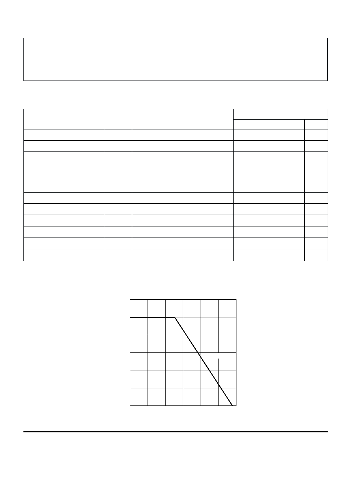
50 75 100 125 175
0.5
0.1
0
ALLOWABLE PACKAGE POWER DISSIPATION IN WATTS
TEMPERATURE IN °C
0.4
0.3
0.2
25
Dwg. GH-069
R
θJA
= 164°C/W
0.6
150
NOTES:1. Maximum supply voltage must be adjusted for power dissipation and ambient temperature.
2. Typical Data is at VCC = 12 V and TA = +25°C and is for design information only.
3421
AND
3422
HALL-EFFECT,
DIRECTION-DETECTION
SENSORS
115 Northeast Cutoff, Box 15036
Worcester, Massachusetts 01615-0036 (508) 853-5000
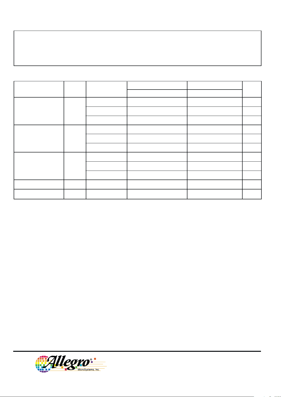
A3421xKA A3422xKA
Characteristic Symbol Test Conditions Min. Typ. Max. Min. Typ. Max. Units
Operate Point B
OP
TA = -40°C 140 185 300 — 29 85 G
TA = +25°C 130 160 280 — 29 75 G
TA = Maximum 120 — 260 — — 75 G
Release Point
3
B
RP
TA = -40°C -300 -190 -140 -85 -19 — G
TA = +25°C -280 -175 -130 -75 -18 — G
TA = Maximum -260 — -120 -75 -16 — G
Hysteresis B
hys
TA = -40°C 280 375 — 10 48 — G
TA = +25°C 260 335 — 10 46 — G
TA = Maximum 240 — — 10 — — G
Operate Differential B
OP1
- B
OP2
——±80 — — ±60 G
Release Differential B
RP1
- B
RP2
——±80 — — ±60 G
MAGNETIC CHARACTERISTICS over operating voltage range.
NOTES:1. Magnetic flux density is measured at most sensitive area of device,
nominally located 0.014” (0.37 mm) below the branded face of the package.
2. Typical Data is at VCC = 12 V and TA = +25°C and is for design information only.
3. As used here, negative flux densities are defined as less than zero (algebraic convention).
 Loading...