

查询A3282供应商查询A3282供应商
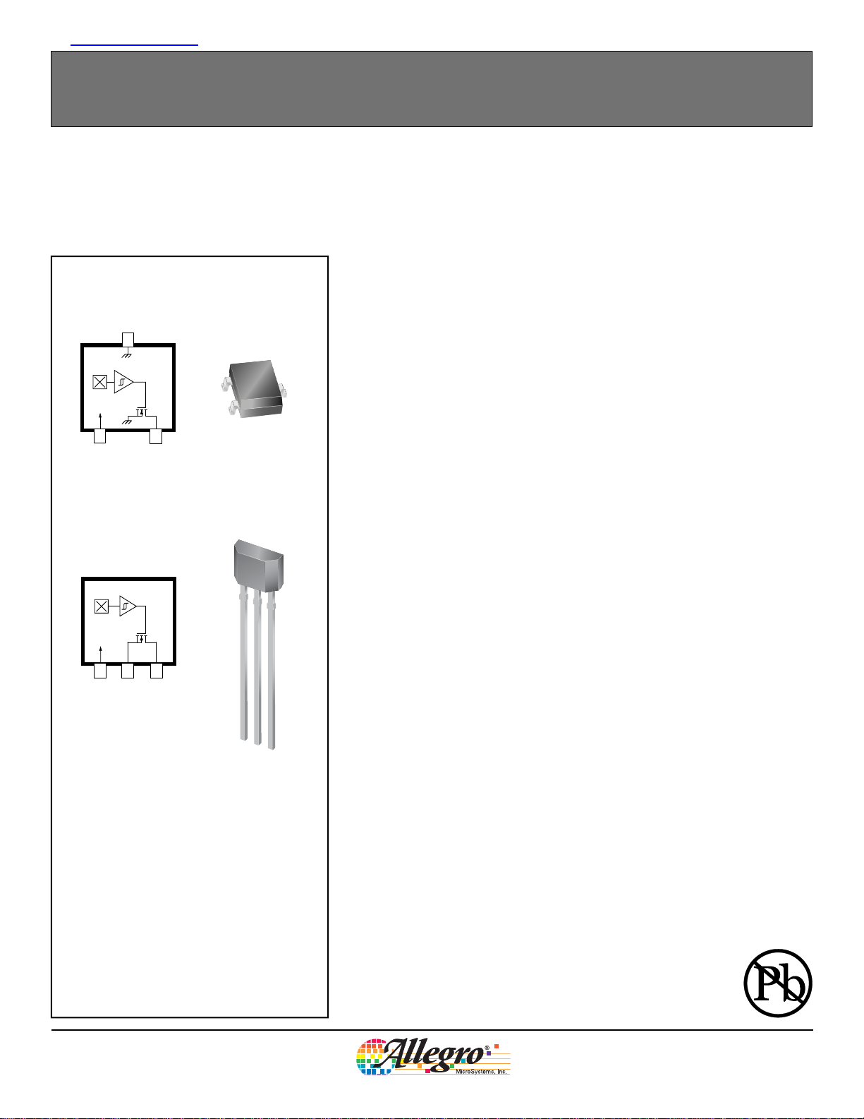
Package LH, 3-pin Surface Mount
GND
3
1
2
VCC
VOUT
Package UA, 3-pin SIP
A3282
Chopper-Stabilized Hall Effect Latch
The A3282 Hall-effect sensor is a temperature stable, stress-resistant latch. Superior high-temperature performance is made possible through an Allegro® patented dynamic offset cancellation that utilizes chopper-stabilization. This method
reduces the offset voltage normally caused by device overmolding, temperature
dependencies, and thermal stress. The A3282 complements the current Allegro
family of chopper-stabilized latching sensors.
The A3282 includes the following on a single silicon chip: voltage regulator, Hall-
3
voltage generator, small-signal amplifi er, chopper stabilization, Schmitt trigger,
and a short circuit protected open-drain output. Advanced BiCMOS wafer fabrication processing is used to take advantage of low-voltage requirements, component
matching, very low input-offset errors, and small component geometries.
This device requires the presence of both south and north polarity magnetic fi elds
for operation. In the presence of a south polarity fi eld of suffi cient strength, the
device output latches on, and only switches off when a north polarity fi eld of suf-
fi cient strength is present.
1 32
VCC
GND
VOUT
1
2
3
AB SO LUTE MAX I MUM RAT INGS
Supply Voltage, VCC..........................................28 V
Reverse-Supply Voltage, V
Output Off Voltage, V
Output Current, I
OUT
OUTSINK
Reverse-Output Current, I
Magnetic Flux Density, B.........................Unlimited
Operating Temperature
Ambient, T
Ambient, T
, Range E..................–40ºC to 85ºC
A
, Range L................–40ºC to 150ºC
A
Maximum Junction, T
Storage Temperature, T
........................–18 V
RCC
............................... 26.5 V
........... Internally Limited
....................–10 mA
ROUT
......................165ºC
J(MAX)
.................. –65ºC to 170ºC
S
The A3282 is rated for operation between the ambient temperatures –40°C and
85°C for the E temperature range, and –40°C to 150°C for the L temperature
range. The two package styles available provide magnetically optimized solutions
for most applications. Package LH is an SOT23W, a miniature low-profi le sur-
face-mount package, while package UA is a three-lead ultramini SIP for throughhole mounting. Each package is available in a lead (Pb) free version, with 100%
matte tin plated leadframes.
Features and Benefi ts
Chopper stabilization
Superior temperature stability
Extremely low switchpoint drift
Insensitive to physical stress
Reverse battery protection
Output short circuit protection
Solid state reliability
Small size
Robust EMC capability
High ESD ratings (HBM)
A3282-DS
Allegro MicroSystems, Inc.
115 Northeast Cutoff, Box 15036
Worcester, Massachusetts 01615-0036 (508) 853-5000
www.allegromicro.com
Chopper-Stabilized Hall Effect Latch
Part Number
A3282ELHLT –
A3282ELHLT-T Yes
A3282EUA –
A3282EUA-T Yes
A3282LLHLT –
A3282LLHLT-T Yes
A3282LUA –
A3282LUA-T Yes
*Contact Allegro for additional packing options.
Pb-
free
Packing* Mounting
7-in. reel, 3000 pieces/reel 3-pin SOT23W surface mount
Bulk, 500 pieces/bag 3-pin SIP through hole
7-in. reel, 3000 pieces/reel 3-pin SOT23W surface mount
Bulk, 500 pieces/bag 3-pin SIP through hole
A3282
Product Selection Guide
Ambient, TA
(°C)
–40 to 85
–40 to 150
B
RP(MIN)
B
(G)
–150 150
OP(MAX)
(G)
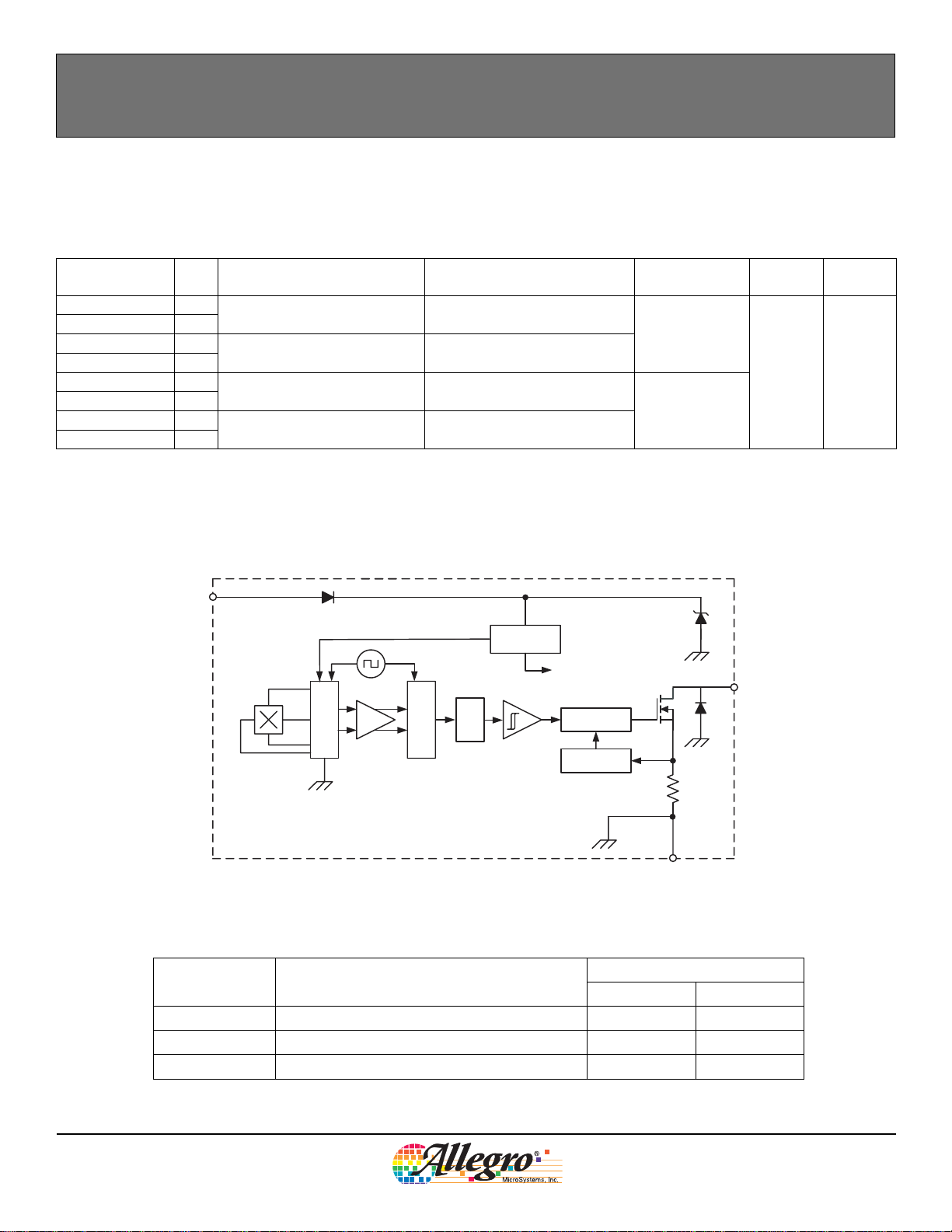
Functional Block Diagram
VCC
Regulator
To All Subcircuits
Amp
Cancellation
Dynamic Offset
Sample and Hold
Filter
Low-Pass
Terminal List
Name Description
VCC Connects power supply to chip 1 1
VOUT Output from circuit 2 3
GND Ground 3 2
Control
Current Limit
Package LH Package UA
VOUT
<1Ω
GND
Number
A3282-DS
Allegro MicroSystems, Inc.
115 Northeast Cutoff, Box 15036
Worcester, Massachusetts 01615-0036 (508) 853-5000
www.allegromicro.com
2
A3282
Chopper-Stabilized Hall Effect Latch
OPERATING CHARACTERISTICS valid over full operating voltage and ambient temperature ranges, unless otherwise noted
Characteristic Symbol Test Conditions Min. Typ. Max. Units
Electrical Characteristics
Supply Voltage
Output Leakage Current I
Output On Voltage V
Output Current Limit I
Power-On Time t
Chopping Frequency f
Output Rise Time
Output Fall Time
Supply Current
Reverse Battery Current I
Supply Zener Clamp Voltage V
Supply Zener Current
Magnetic Characteristics
Operate Point B
Release Point B
Hysteresis B
1
Maximum voltage must be adjusted for power dissipation and junction temperature, see Power Derating section.
2
CS = oscilloscope probe capacitance.
3
Maximum current limit is equal to the maximum I
4
Magnetic fl ux density, B, is indicated as a negative value for north-polarity magnetic fi elds, and as a positive value for south-polarity magnetic fi elds.
This so-called algebraic convention supports arithmetic comparison of north and south polarity values, where the relative strength of the fi eld is indicated
by the absolute value of B, and the sign indicates the polarity of the fi eld (for example, a –100 G fi eld and a 100 G fi eld have equivalent strength, but
opposite polarity).
1
2
2
3
4
V
CC
OUTOFF
OUT(SAT)IOUT
OM
PO
c
t
r
t
f
I
CCON
I
CCOFF
RCC
Z
I
Z
OP
RP
HYS
Operating, TJ < 165°C 3.6 – 24 V
V
OUT
B > B
VCC > 3.6 V – 8 50 µs
R
LOAD
R
LOAD
B > B
B < B
V
RCC
ICC = 8 mA; TA = 25°C 28 – – V
VS = 28 V – – 8 mA
South pole adjacent to branded face of device 70 110 150
North pole adjacent to branded face of device –150 –110 –70
B
CC(MAX)
= 24 V, B < B
= 20 mA, B > B
OP
RP
OP
– – 10 µA
– 250 500 mV
30 – 60 mA
– 200 – kHz
= 820 Ω, CS = 20 pF – 0.2 1 µs
= 820 Ω, CS = 20 pF – 0.2 1 µs
OP
RP
– 1.6 5 mA
– 1.6 5 mA
= –18 V – – –2 mA
– B
OP
+ 3 mA.
RP
140 220 300
G
G
G
A3282-DS
DEVICE QUALIFICATION PROGRAM
Contact Allegro for information.
EMC (Electromagnetic Compatibility) REQUIREMENTS
Contact Allegro for information.
Allegro MicroSystems, Inc.
115 Northeast Cutoff, Box 15036
Worcester, Massachusetts 01615-0036 (508) 853-5000
www.allegromicro.com
3
A3282
Chopper-Stabilized Hall Effect Latch
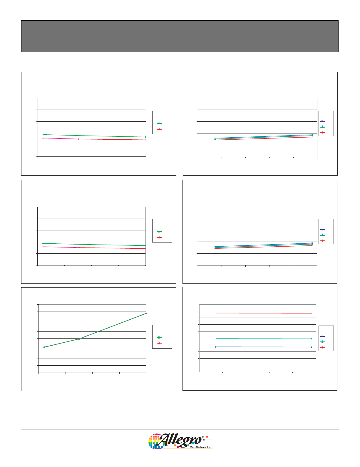
Electrical Characteristic Data
Supply Current (On) versus Ambient Temperature
5.0
4.0
3.0
(mA)
2.0
CCON
I
1.0
0
–50 0 50 100 150
TA (°C)
Supply Current (Off) versus Ambient Temperature
5.0
4.0
3.0
(mA)
2.0
CCOFF
I
VCC (V)
VCC (V)
Supply Current (On) versus Supply Voltage
5.0
4.0
24
3.6
3.0
(mA)
2.0
CCON
I
1.0
0
0 5 10 15 20 25
VCC (V)
Supply Current (Off) versus Supply Voltage
5.0
4.0
3.0
24
3.6
(mA)
2.0
CCOFF
I
TA (°C)
–40
25
150
TA (°C)
–40
25
150
1.0
0
–50 0 50 100 150
TA (°C)
Output Voltage (On) versus Ambient Temperature
500
450
400
350
300
(mV)
250
200
OUT(SAT)
150
V
100
50
0
–50 0 50 100 150
TA (°C)
VCC (V)
24
3.6
1.0
0
0 5 10 15 20 25
VCC (V)
Output Voltage (On) versus Supply Voltage
500
450
400
350
300
(mV)
250
200
OUT(SAT)
150
V
100
50
0
0 5 10 15 20 25
VCC (V)
TA (°C)
–40
25
150
A3282-DS
Allegro MicroSystems, Inc.
115 Northeast Cutoff, Box 15036
Worcester, Massachusetts 01615-0036 (508) 853-5000
www.allegromicro.com
4
 Loading...