

Allegri 020521010FR001 User Manual
020521-010-FR001 3-Light wall lamp
Customer Service :(702)361-4345,(800)525-2655,customer.service@kalco.com
WARNING - TO REDUCE THE RISK OF FIRE OR INJURY:
1.lf you are unfamiliar with electrical wiring, call a qualified electrician to install this unit .More than
one person may be necessary to install fixture ,make sure you have enough qualified help.
2.Turn off the power to the fixture's circuit at the service panel. Use a voltage detector to verify that
the power is off.
3.DO NOT install bulb which exceeds the maximum wattage specified on the socket label.
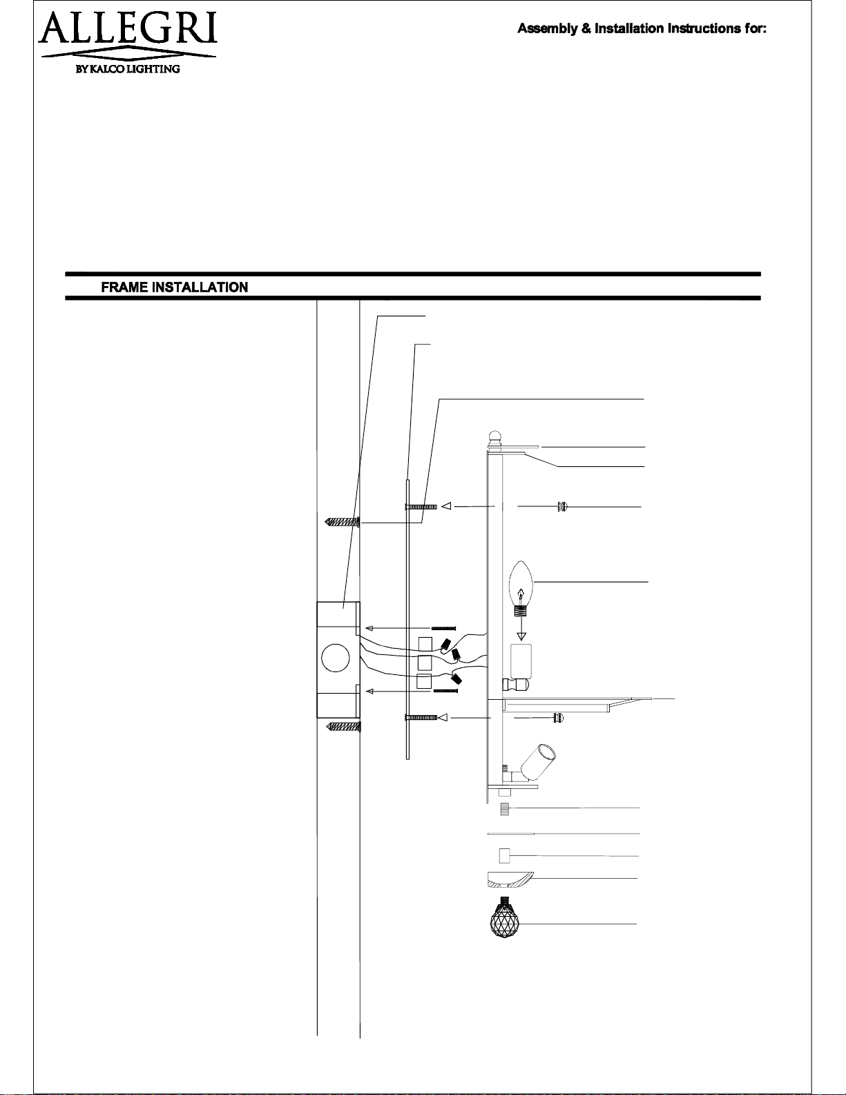
1-Outlet box with 2 scr ews (not supp l i ed)
Step 1. Fix fixture crossbar 2 to outlet box 1
with original outlet box screws. Mark top and
bottom cross bar slots in the wall, remove
crossbar then install anchor screws in the
wall.
Step 2. Screw Crossbar 2 to outlet box 1 with
original outlet box screws. Make sure
crossbar studs are pointing away from wall.
Reinforce cross bar with top and bottom
anchor screws.
Step 3. Get fixture frame a few inches
close to wall and connect wires: Connect
fixture ribbed wire (L) to power supply
black wire. Connect fixture smooth wire
(N) to power supply white wire. Connect
fixture silver or copper bare wire (G) to
power supply green wire.
Step 4. Align fixture back plate holes to
crossbar studs 2 and fix it flat to wall,
secure fixture with decorative nuts 5, then
Install light bulbs.
2-Cross bar with stu ds
Anchor screws
3-Top slott ed half disc
4-Top Disc w/holes
5-Decora ti v e nuts
Light bulb candelabr a 40w max.
L
N
G
6-Middle slotted ban d
Step 5. Install threaded rod 7 to bottom
of fixture, then install parts 8, 9, 10, and
11.
Proceed to install crystal set; follow
directions on pages 2 and 3 .
7-Threaded Rod
8-Botto m slotted half di sc
9-Connector
10-Crystal Bobeche
11-Crystal ball ( I )
P1
020521-010-FR001 3-Light wall lamp
Customer Service :(702) 361-4345, (800)525-2655, customer.service@kalco.com
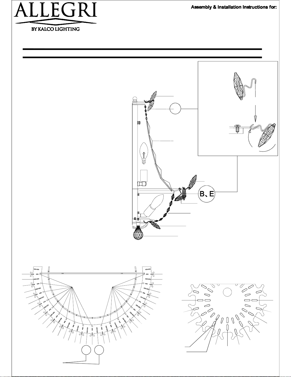
TRIMMING INSTRUCTIONS:
Step1. Carefully unpack all parts from carton,
unwrap the crystals, lay them down on a clean soft
cloth. Identify and organize crystals as shown in
page 3.
Step2. Install crystal strands (C) first hung Thinner
side of strand to top ring then to Middle ring.
Step3. Install crystal strands (G) first hung Thicker
side of strand to Middle ring then to bottom.
Step4. Refer to fig.1B on top right and install
crystals (B) to top slotted half disc 3. Then install
crystal (A) following FIG.2 top view pattern.
A
B
Follow these steps
to install crystal B
and E
1-Place crystal upside
down as shown
2-Insert crystal pin on
first hole
3-Turn crystal down
and insert pin to
second hole
4-release.
C
FIG.1B
Step5. Refer to FIG.1B on top right and start
installing 2 crystals (E) on center of Middle slotted
band as shown below in FIG.3
Make pattern as shown from center to right then
from center to left: install 2 crystals (B) and 2 (D),
then 2 (E) and 2 (D) then repeat.
Step6. Install all crystals (F) from the back and
underneath of middle slotted band.
Step7. Remove parts 11, 10 and 9 to release
bottom slotted half disc 8. Install crystals (H) and
place it back, install back parts 9, 10, and ( I ).
Turn switch on.
FIG.3 TOP VIEW
6-Middle s lo tted band
D
E
D
E
D
B
D
B
D
E
D
E
D
F F
B
D
B
D
D
D
E
E
D
F
G
H
I
D
E
D
E
D
B
D
B
D
E
D
E
D
B
D
B
B
A
B
A
1st hole
2nd hole
B
FIG.2 TOP VIEW
3-sl otted ha l f di sc
A
B
B
A
B
A
B
A
Step5. Start here.
P2
 Loading...