

Page 1

Alienware Area-51 Threadripper
Edition R6
Service Manual
Computer Model: Alienware Area-51 R6
Regulatory Model: D03X
Regulatory Type: D03X003
Page 2
Notes, cautions, and warnings
NOTE: A NOTE indicates important information that helps you make
better use of your product.
CAUTION: A CAUTION indicates either potential damage to
hardware or loss of data and tells you how to avoid the problem.
WARNING: A WARNING indicates a potential for property damage,
personal injury, or death.
© 2018 Dell Inc. or its subsidiaries. All rights reserved. Dell, EMC, and other
trademarks are trademarks of Dell Inc. or its subsidiaries. Other trademarks may be
trademarks of their respective owners.
2018 - 02
Rev. A00
Page 3

Contents
Before working inside your computer........................ 13
Before you begin ........................................................................... 13
Safety instructions........................................................................... 13
Recommended tools........................................................................14
Screw list........................................................................................ 15
After working inside your computer...........................19
Technical overview.......................................................20
Inside view of your computer.......................................................... 20
Right view.................................................................................21
Left view.................................................................................. 22
System-board components..............................................................23
I/O-board components.................................................................. 25
Lifting the computer....................................................27
Procedure...................................................................................... 27
Removing the stability foot.........................................28
Procedure...................................................................................... 28
Replacing the stability foot......................................... 31
Procedure.......................................................................................31
Removing the side panels............................................32
Procedure...................................................................................... 32
3
Page 4

Replacing the side panels............................................34
Procedure...................................................................................... 34
Removing the battery..................................................35
Prerequisites...................................................................................35
Procedure......................................................................................35
Replacing the battery..................................................37
Procedure...................................................................................... 37
Post-requisites................................................................................37
Removing the battery case..........................................38
Prerequisites...................................................................................38
Procedure...................................................................................... 38
Replacing the battery case..........................................40
Procedure......................................................................................40
Post-requisites............................................................................... 40
Removing the hard drive............................................. 41
Prerequisites...................................................................................41
Procedure.......................................................................................41
Replacing the hard drive.............................................44
Procedure......................................................................................44
Post-requisites................................................................................44
Removing the U.2 fan..................................................45
Prerequisites.................................................................................. 45
Procedure......................................................................................45
4
Page 5

Replacing the U.2 fan..................................................47
Procedure...................................................................................... 47
Post-requisites................................................................................47
Removing the right AlienFX side-panel connector... 48
Prerequisites...................................................................................48
Procedure......................................................................................48
Replacing the right AlienFX side-panel connector....51
Procedure.......................................................................................51
Post-requisites................................................................................ 51
Removing the left AlienFX side-panel connector......52
Prerequisites.................................................................................. 52
Procedure......................................................................................52
Replacing the left AlienFX side-panel connector......55
Procedure......................................................................................55
Post-requisites................................................................................55
Removing the I/O board............................................ 56
Prerequisites.................................................................................. 56
Procedure......................................................................................56
Replacing the I/O board.............................................58
Post-requisites................................................................................58
Removing the drive-bay heat sensor cable................ 59
Prerequisites.................................................................................. 59
Procedure......................................................................................59
5
Page 6

Replacing the drive-bay heat sensor cable................ 62
Procedure......................................................................................62
Post-requisites................................................................................62
Removing the memory modules..................................63
Prerequisites...................................................................................63
Procedure...................................................................................... 63
Replacing the memory modules..................................65
Procedure......................................................................................65
Post-requisites................................................................................65
Removing the graphics card....................................... 66
Prerequisites.................................................................................. 66
Procedure......................................................................................66
Replacing the graphics card........................................69
Procedure......................................................................................69
Post-requisites................................................................................69
Removing multiple graphics cards..............................70
Prerequisites.................................................................................. 70
Procedure......................................................................................70
Replacing multiple graphics cards..............................74
Procedure...................................................................................... 74
Post-requisites................................................................................74
Removing the wireless card........................................ 75
Prerequisites...................................................................................75
Procedure...................................................................................... 75
6
Page 7

Replacing the wireless card.........................................77
Procedure...................................................................................... 77
Post-requisites................................................................................77
Removing the coin-cell battery...................................78
Prerequisites...................................................................................78
Procedure...................................................................................... 78
Replacing the coin-cell battery...................................80
Procedure......................................................................................80
Post-requisites................................................................................80
Removing the top fan...................................................81
Prerequisites................................................................................... 81
Procedure.......................................................................................81
Replacing the top fan.................................................. 83
Procedure...................................................................................... 83
Post-requisites................................................................................83
Removing the logo board............................................84
Prerequisites...................................................................................84
Procedure......................................................................................85
Replacing the logo board............................................87
Procedure...................................................................................... 87
Post-requisites................................................................................87
Removing the solid-state drive...................................88
Prerequisites...................................................................................88
Procedure...................................................................................... 88
7
Page 8

Replacing the solid-state drive...................................90
Procedure......................................................................................90
Post-requisites................................................................................ 91
Removing the PCI fan................................................. 92
Prerequisites.................................................................................. 92
Procedure......................................................................................92
Replacing the PCI fan................................................. 94
Procedure......................................................................................94
Post-requisites................................................................................94
Removing the front-bezel heat sensor cable..............95
Prerequisites.................................................................................. 95
Procedure......................................................................................95
Replacing the front-bezel heat-sensor cable.............97
Procedure...................................................................................... 97
Post-requisites................................................................................97
Removing the processor liquid-cooling assembly......98
Prerequisites.................................................................................. 98
Procedure......................................................................................98
Replacing the processor liquid-cooling assembly.... 101
Procedure.....................................................................................101
Post-requisites..............................................................................102
Removing the processor............................................103
Prerequisites.................................................................................103
Procedure.................................................................................... 103
8
Page 9

Replacing the processor............................................106
Procedure....................................................................................106
Post-requisites..............................................................................107
Removing the power-supply unit............................. 109
Prerequisites.................................................................................109
Procedure....................................................................................109
Replacing the power-supply unit.............................. 113
Procedure..................................................................................... 113
Post-requisites...............................................................................114
Removing the system board...................................... 115
Prerequisites................................................................................. 115
Procedure.....................................................................................115
Replacing the system board...................................... 117
Procedure..................................................................................... 117
Post-requisites...............................................................................117
Removing the handle bars......................................... 119
Prerequisites................................................................................. 119
Procedure.................................................................................... 120
Replacing the handle bars.........................................126
Procedure.................................................................................... 126
Post-requisites..............................................................................126
Removing the front bezel ......................................... 127
Prerequisites.................................................................................127
Procedure.....................................................................................127
9
Page 10

Replacing the front bezel..........................................130
Procedure.................................................................................... 130
Post-requisites..............................................................................130
Removing the rear bezel............................................131
Prerequisites..................................................................................131
Procedure..................................................................................... 131
Replacing the rear bezel............................................136
Procedure.................................................................................... 136
Post-requisites..............................................................................136
Removing the base panel...........................................137
Prerequisites................................................................................. 137
Procedure.....................................................................................138
Replacing the base panel...........................................142
Procedure.................................................................................... 142
Post-requisites..............................................................................142
Removing the top tron-lighting cable.......................143
Prerequisites.................................................................................143
Procedure.................................................................................... 143
Replacing the top tron-lighting cable...................... 145
Procedure.................................................................................... 145
Post-requisites..............................................................................145
Removing the bottom tron-lighting cable................ 146
Prerequisites.................................................................................146
Procedure.................................................................................... 146
10
Page 11

Replacing the bottom tron-lighting cable................ 149
Procedure.................................................................................... 149
Post-requisites..............................................................................149
Removing the antenna cables................................... 150
Prerequisites................................................................................ 150
Procedure....................................................................................150
Replacing the antenna cables................................... 155
Procedure.................................................................................... 155
Post-requisites..............................................................................155
Downloading drivers.................................................157
Downloading the audio driver.......................................................157
Downloading the graphics driver...................................................158
Downloading the USB driver.........................................................158
Downloading the chipset driver.................................................... 159
Downloading the network driver...................................................160
BIOS setup program..................................................162
Boot Sequence.............................................................................162
Navigation keys............................................................................162
BIOS overview..............................................................................163
Entering BIOS setup program........................................................163
System setup options.....................................................................164
System and setup password...........................................................170
Assigning a system password and setup password..................... 170
Deleting or changing an existing system and or setup password..171
Clearing CMOS Settings..........................................................172
Clearing Forgotten Passwords.................................................. 173
11
Page 12

Troubleshooting.........................................................175
Flashing the BIOS......................................................................... 175
Flashing BIOS (USB key)...............................................................175
Enhanced Pre-Boot System Assessment (ePSA) diagnostics.............176
Running the ePSA diagnostics..................................................176
Diagnostics................................................................................... 177
Wi-Fi power cycle.........................................................................177
Getting help and contacting Alienware................... 178
Self-help resources........................................................................178
Contacting Alienware....................................................................178
12
Page 13
Before working inside your computer
NOTE: The images in this document may dier from your computer
depending on the conguration you ordered.
Before you begin
1 Save and close all open les and exit all open applications.
2 Shut down your computer. Click Start → Power → Shut down.
NOTE: If you are using a dierent operating system, see the
documentation of your operating system for shut-down instructions.
3 Disconnect your computer and all attached devices from their electrical
outlets.
4 Disconnect all attached network devices and peripherals, such as keyboard,
mouse, and monitor from your computer.
5 Remove any media card and optical disc from your computer, if applicable.
6 After the computer is unplugged, press and hold the power button for 5
seconds to ground the system board.
Safety instructions
Use the following safety guidelines to protect your computer from potential
damage and ensure your personal safety.
WARNING: Before working inside your computer, read the safety
information that shipped with your computer. For more safety best
practices, see the Regulatory Compliance home page at www.dell.com/
regulatory_compliance.
WARNING: Disconnect all power sources before opening the computer
cover or panels. After you nish working inside the computer, replace all
covers, panels, and screws before connecting to the electrical outlet.
13
Page 14
CAUTION: To avoid damaging the computer, ensure that the work
surface is at and clean.
CAUTION: To avoid damaging the components and cards, handle them by
their edges, and avoid touching pins and contacts.
CAUTION: You should only perform troubleshooting and repairs as
authorized or directed by the Dell technical assistance team. Damage due
to servicing that is not authorized by Dell is not covered by your
warranty. See the safety instructions that shipped with the product or at
www.dell.com/regulatory_compliance.
CAUTION: Before touching anything inside your computer, ground
yourself by touching an unpainted metal surface, such as the metal at the
back of the computer. While you work, periodically touch an unpainted
metal surface to dissipate static electricity, which could harm internal
components.
CAUTION: When you disconnect a cable, pull on its connector or on its
pull tab, not on the cable itself. Some cables have connectors with locking
tabs or thumb-screws that you must disengage before disconnecting the
cable. When disconnecting cables, keep them evenly aligned to avoid
bending any connector pins. When connecting cables, ensure that the
ports and connectors are correctly oriented and aligned.
CAUTION: Press and eject any installed card from the media-card reader.
Recommended tools
The procedures in this document may require the following tools:
• Philips screwdriver #1
• Philips screwdriver #2
• Torx #20 (T20) screwdriver
• Flat-head screwdriver
• Plastic scribe
14
Page 15
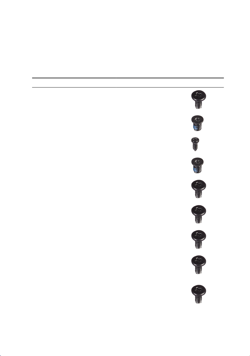
Screw list
The following table provides the list of screws that are used for securing dierent
components.
Table 1. Screw list
Component Secured to Screw type Quantity Screw image
Stability foot Computer #6-32x6 2
Security-cable
slot latch
Battery-case
door
Battery case Chassis #6-32x5.2 2
Hard-drive
assembly
Hard drive Hard-drive
U.2 fan Hard-drive
Right AlienFX
side-panel
connector
assembly
Right AlienFX
side-panel
connector
Computer #6-32x5.2 1
Battery case M2x5.7 1
Chassis #6-32x6 1
#6-32x3.6 4
bracket
#6-32x6 2
assembly
bracket
Chassis #6-32x6 2
Bracket #6-32x6 1
15
Page 16

Component Secured to Screw type Quantity Screw image
Left AlienFX
side-panel
connector
assembly
Left AlienFX
side-panel
connector
I/O board Chassis #6-32x6 5
Wireless card Chassis M2x3 1
Top fan Chassis #6-32x6 1
Logo board Chassis #6-32x6 1
Logo board Bracket #6-32x6 6
Chassis #6-32x6 2
Bracket #6-32x6 1
Solid-state
drive
PCI fan Chassis M3x5.25 2
Fan shroud PCI fan M5x10 4
16
System board M2x2.5 1
Page 17
Component Secured to Screw type Quantity Screw image
Processor
liquid-cooling
assembly
Chassis M5x10 4
Power-supply
unit
System-board Chassis #6-32x6 9
Rear-handle
bar
Front-handle
bar
Bottom-handle
bar
Front bezel Chassis #6-32x6 5
Rear bezel Chassis #6-32x6 4
Chassis #6-32x6 4
Chassis #6-32x6.5 14
Chassis #6-32x6.5 14
Chassis #6-32x6.5 14
Rear bezel Chassis M3x5 3
Base panel Chassis #6-32x6 4
17
Page 18
Component Secured to Screw type Quantity Screw image
Base panel Chassis #6-32x6 5
Antennas Chassis #6-32x6 6
18
Page 19

After working inside your computer
CAUTION: Leaving stray or loose screws inside your computer may
severely damage your computer.
1 Replace all screws and ensure that no stray screws remain inside your
computer.
2 Connect any external devices, peripherals, or cables you removed before
working on your computer.
3 Replace any media cards, discs, or any other parts that you removed before
working on your computer.
4 Connect your computer and all attached devices to their electrical outlets.
5 Turn on your computer.
19
Page 20
Technical overview
WARNING: Before working inside your computer, read the safety
information that shipped with your computer and follow the steps in
Before working inside your computer. After working inside your
computer, follow the instructions in After working inside your computer.
For more safety best practices, see the Regulatory Compliance home
page at
Inside view of your computer
To view the dierent components installed in your computer. See “Left view” and
“Right view”.
www.dell.com/regulatory_compliance.
20
Page 21
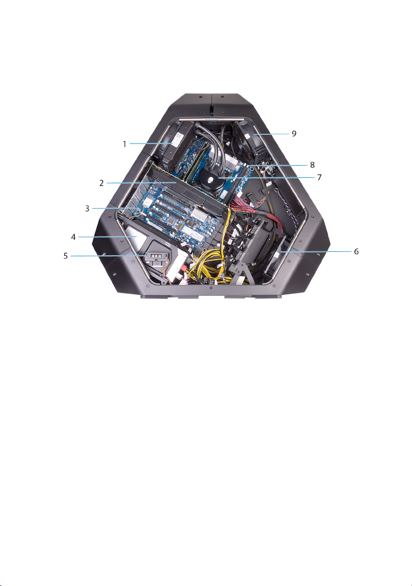
Right view
Figure 1. Right view
1 I/O board (IO BRD) 2 U.2 2.5–inch drive bracket
(HDD3/HDD4)
3 drive-bay heat-sensor 4 U.2 2.5–inch drive bracket
(HDD1/HDD2)
5 AlienFX side-panel connector 6 rear I/O accessibility lighting
batteries
7 3.5-inch drive bracket (HDD1) 8 3.5-inch drive bracket (HDD2)
9 3.5-inch drive bracket (HDD3)
21
Page 22
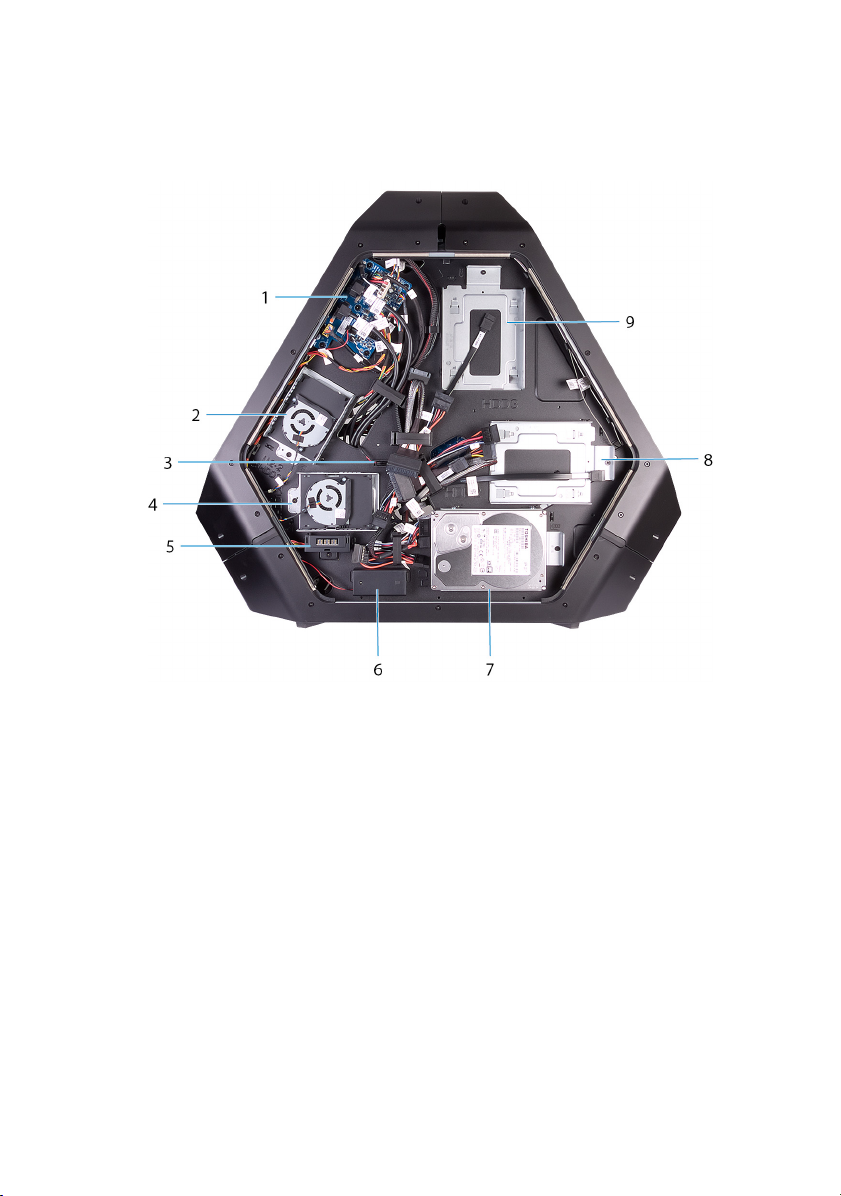
Left view
Figure 2. Left view
1 processor liquid-cooling assembly
fan
3 system board 4 power-supply unit
5 AlienFX side-panel connector 6 PCI fan
7 processor liquid-cooling assembly
pump
9 top fan
22
2 graphics card
8 memory modules
Page 23
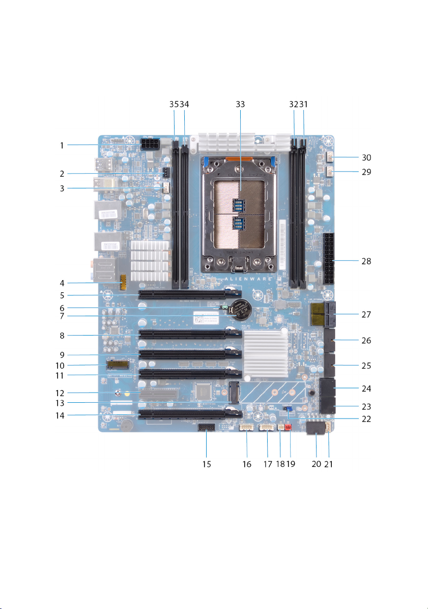
System-board components
1 processor-power connector (CPU
PWR1)
2 processor liquid-cooling
assembly pump-fan connector
(PUMP_FAN1)
23
Page 24

3 processor liquid cooling-assembly
fan (LCM_FAN1)
5 PCI-Express slot (SLOT1) 6 CMOS reset jumper
7 coin-cell battery socket (BAT1) 8 PCI-Express slot (SLOT3)
9 PCI-Express slot (SLOT4) 10 WLAN connector (M2_WLAN1)
11 PCI-Express slot (SLOT5) 12 PCI-Express slot (SLOT6)
13 solid-state drive slot (M2_SSD1)
15 low pin count debug header
(LPC1)
17 USB connector (USB1) 18 chassis heat-sensor connector
4 audio connector (FP_AUDIO1)
(CMOS_CLR)
14 PCI-Express slot (SLOT7)
16 LED Power Switch (PANEL1)
(SENSOR2)
19 drive-bay heat-sensor connector
(SENSOR1)
21 PCI-Express fan 1 connector
(PCI_FAN1)
23 SATA drive connector (HDD
_SATA_3_4)
25 USB connector (USB3_MB2) 26 USB connector (USB3_MB1)
27 U.2 SSD connector
29 processor liquid-cooling assembly
fan connector (MID_FAN1)
31 memory-module slot (DIMM2) 32 memory-module slot (DIMM1)
33 processor socket (CPU1) 34 memory-module slot (DIMM3)
35 memory-module slot (DIMM4)
20 PCI-Express power connector
(PCIE_PWR1)
22 password reset jumper
(PW_CLR)
24 SATA drive connector
(HDD_SATA_1_2)
28 Advanced Technology xTended
(ATX) power connector (ATX
PWR1)
30 top fan connector (TOP_FAN1)
24
Page 25
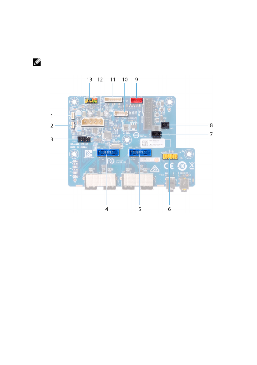
I/O-board components
NOTE: The location of the connectors may vary based on the selections
you made at the time of purchase.
Figure 3. I/O-board components
1 Fan connector (U2_FAN1) 2 Fan connector (U2_FAN2)
3 USB connector (USB1) 4 front I/O connector
(USB3_FIO1)
5 front I/O connector (USB3_FIO2) 6 audio connector (AUDIOIO1)
7 rear I/O accessibility lighting
battery connector (VBAT1)
9 right theater-lighting connector
(POGO_IN_R1)
11 logo board connector (LOGO1) 12 main-power connector (PWR1)
8 rear I/O accessibility lighting
connector (PORCH_LIGHT1)
10 left theater-lighting connector
(POGO_IN_L1)
25
Page 26

13 front I/O control connector
(FIO_PWR1)
26
Page 27
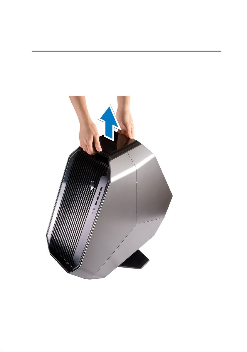
Lifting the computer
Procedure
1 With both hands, hold the handle located on top of the computer.
2 Lift the computer.
27
Page 28
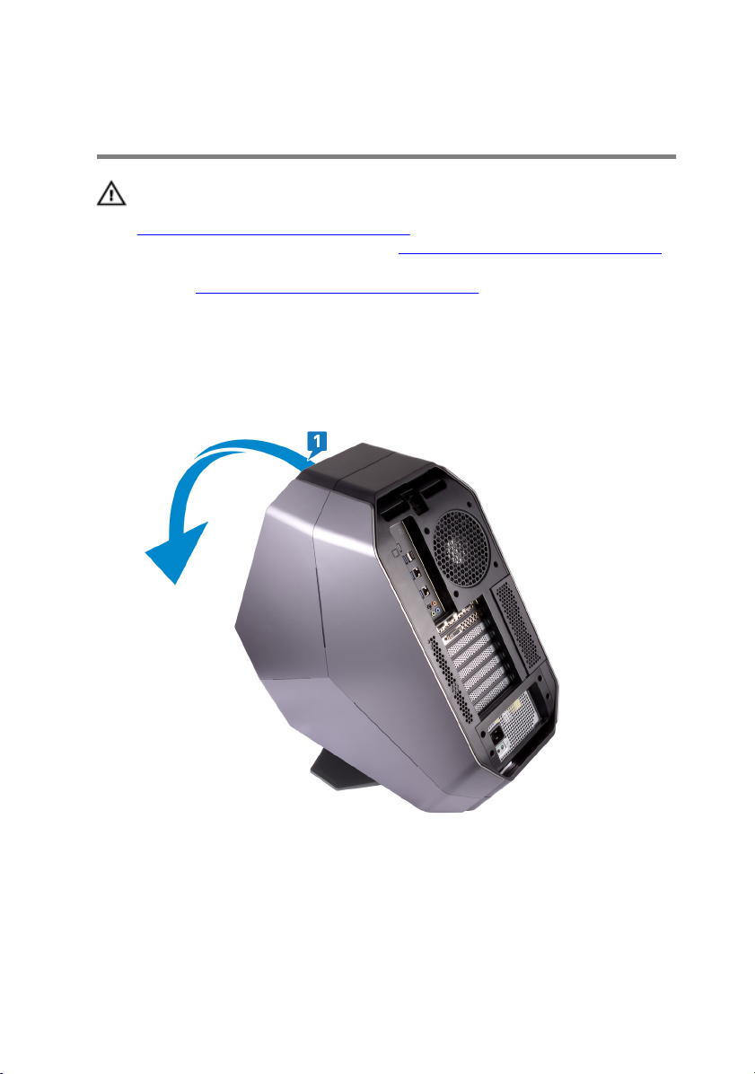
Removing the stability foot
WARNING: Before working inside your computer, read the safety
information that shipped with your computer and follow the steps in
Before working inside your computer. After working inside your
computer, follow the instructions in After working inside your computer.
For more safety best practices, see the Regulatory Compliance home
page at
Procedure
1 Tilt the computer towards the front until the base is facing up.
www.dell.com/regulatory_compliance.
2 Remove the two screws (#6-32x6) that secure the stability foot to the
computer.
28
Page 29
3 Lift the stability foot o the computer.
29
Page 30
4 Tilt the computer back to the upright position.
30
Page 31

Replacing the stability foot
WARNING: Before working inside your computer, read the safety
information that shipped with your computer and follow the steps in
Before working inside your computer. After working inside your
computer, follow the instructions in After working inside your computer.
For more safety best practices, see the Regulatory Compliance home
page at
Procedure
1 Tilt the computer towards the front until the base is facing up.
2 Align the screw holes on the stability foot with the screw holes on the base of
the computer and replace the two screws (#6-32x6).
3 Tilt the computer back to the upright position.
www.dell.com/regulatory_compliance.
31
Page 32

Removing the side panels
WARNING: Before working inside your computer, read the safety
information that shipped with your computer and follow the steps in
Before working inside your computer. After working inside your
computer, follow the instructions in After working inside your computer.
For more safety best practices, see the Regulatory Compliance home
page at
Procedure
NOTE: Make sure that you remove the security cable from the securitycable slot (if applicable).
1 Remove the screw (#6-32x5.2) that secures the security-cable slot latch.
The security-cable slot latch slides to the unlocked position.
2 Lift the release panel to open the right side-panel.
www.dell.com/regulatory_compliance.
32
Page 33

3 Pull and lift the right side-panel away from the chassis.
4 Repeat the procedure from step 2 to step 3 on the left side-panel.
33
Page 34

Replacing the side panels
WARNING: Before working inside your computer, read the safety
information that shipped with your computer and follow the steps in
Before working inside your computer. After working inside your
computer, follow the instructions in After working inside your computer.
For more safety best practices, see the Regulatory Compliance home
page at
Procedure
1 Align the tabs on the right side-panel with the slots on the right side of the
computer and snap the panel to lock it in place.
2 Repeat step 1 to replace the left side-panel.
3 Slide and hold the security-cable slot latch in the locked position.
4 Replace the screw (#6-32x5.2) that secures the security-cable slot latch.
www.dell.com/regulatory_compliance.
34
Page 35

Removing the battery
WARNING: Before working inside your computer, read the safety
information that shipped with your computer and follow the steps in
Before working inside your computer. After working inside your
computer, follow the instructions in After working inside your computer.
For more safety best practices, see the Regulatory Compliance home
page at
Prerequisites
Remove the right side-panel. See “Removing the side panels”.
Procedure
1 Remove the screw (M2x5.7) that secures the battery-case door to the battery
case.
2 Slide and open the battery-case door.
www.dell.com/regulatory_compliance.
35
Page 36

3 Remove the batteries from the battery case.
36
Page 37

Replacing the battery
WARNING: Before working inside your computer, read the safety
information that shipped with your computer and follow the steps in
Before working inside your computer. After working inside your
computer, follow the instructions in After working inside your computer.
For more safety best practices, see the Regulatory Compliance home
page at
Procedure
1 Insert the batteries into the battery case.
2 Slide and close the battery-case door.
3 Replace the screw (M2x5.7) that secures the battery-case door to the battery
case.
Post-requisites
Replace the right side-panel. See “Replacing the side panels”.
www.dell.com/regulatory_compliance.
37
Page 38

Removing the battery case
WARNING: Before working inside your computer, read the safety
information that shipped with your computer and follow the steps in
Before working inside your computer. After working inside your
computer, follow the instructions in After working inside your computer.
For more safety best practices, see the Regulatory Compliance home
page at
Prerequisites
1 Remove the stability foot.
2 Remove the right side-panel. See “Removing the side panels”.
3 Remove the battery.
Procedure
1 Lay the chassis on the left side.
2 Press the release tabs on the cable connector to disconnect the battery-case
cable from the I/O board.
3 Remove the battery-case cable from the routing guides on the chassis.
4 Remove the two screws (#6-32x5.2) that secure the battery case to the
chassis.
www.dell.com/regulatory_compliance.
38
Page 39

5 Lift the battery case o the chassis.
39
Page 40

Replacing the battery case
WARNING: Before working inside your computer, read the safety
information that shipped with your computer and follow the steps in
Before working inside your computer. After working inside your
computer, follow the instructions in After working inside your computer.
For more safety best practices, see the Regulatory Compliance home
page at
Procedure
1 Align the screw holes on the battery case with the screw holes on the chassis.
2 Replace the two screws (#6-32x5.2) that secure the battery case to the
chassis.
3 Route the battery-case cable through the routing guides on the chassis.
4 Connect the battery-case cable to the I/O board.
Post-requisites
1 Replace the battery.
2 Replace the right side-panel. See “Replacing the side panels”.
3 Replace the stability foot.
www.dell.com/regulatory_compliance.
40
Page 41

Removing the hard drive
WARNING: Before working inside your computer, read the safety
information that shipped with your computer and follow the steps in
Before working inside your computer. After working inside your
computer, follow the instructions in After working inside your computer.
For more safety best practices, see the Regulatory Compliance home
page at
CAUTION: Hard drives are fragile. Exercise care when handling the hard
drive.
CAUTION: To avoid data loss, do not remove the hard drive while the
computer is in sleep or on state.
Prerequisites
1 Remove the stability foot.
2 Remove the left and right side-panels. See “Removing the side panels”.
Procedure
1 Lay the chassis on the left side.
2 Disconnect the power cable and data cable from the hard-drive assembly
(HDD1).
3 Remove the screw (#6-32x6) that secures the hard-drive assembly (HDD1)
to the chassis.
www.dell.com/regulatory_compliance.
41
Page 42

4 Using the tab, slide and remove the hard-drive assembly (HDD1) from the
chassis.
5 Remove the four screws (#6-32x3.6) that secure the hard-drive bracket to
the hard drive.
42
Page 43

6 Slide and remove the hard drive from the hard-drive bracket.
NOTE: Repeat step 2 to step 6 to remove any other hard drives
(HDD2 and HDD3) installed in your computer.
43
Page 44

Replacing the hard drive
WARNING: Before working inside your computer, read the safety
information that shipped with your computer and follow the steps in
Before working inside your computer. After working inside your
computer, follow the instructions in After working inside your computer.
For more safety best practices, see the Regulatory Compliance home
page at
CAUTION: Hard drives are fragile. Exercise care when handling the hard
drive.
Procedure
1 Align the screw holes on the hard-drive bracket with the screw holes on the
hard drive (HDD1).
2 Replace the four screws (#6-32x3.6) that secure the hard drive to the hard-
drive bracket.
3 Place the hard-drive assembly (HDD1) in the chassis.
4 Replace the screw (#6-32x6) that secures the hard-drive assembly (HDD1)
to the chassis.
5 Connect the power cable and data cable to the hard drive (HDD1).
www.dell.com/regulatory_compliance.
NOTE: Repeat step 2 to step 5 to replace any other hard drives
(HDD2 and HDD3) installed in your computer.
Post-requisites
1 Replace the left and right side-panels. See “Replacing the side panels”.
2 Replace the stability foot.
44
Page 45

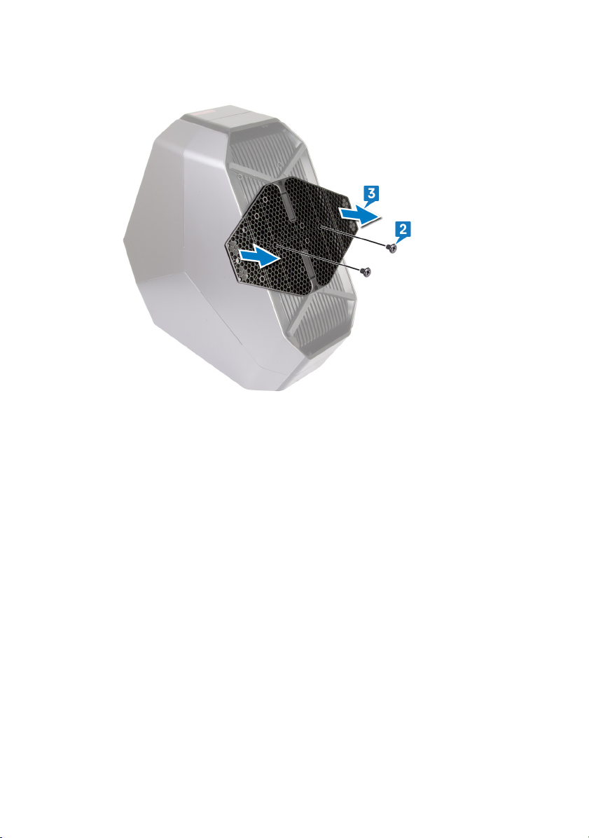
Removing the U.2 fan
WARNING: Before working inside your computer, read the safety
information that shipped with your computer and follow the steps in
Before working inside your computer. After working inside your
computer, follow the instructions in After working inside your computer.
For more safety best practices, see the Regulatory Compliance home
page at
Prerequisites
1 Remove the stability foot.
2 Remove the left and right side-panels. See “Removing the side panels”.
Procedure
1 Lay the chassis on the left side.
2 Disconnect the U.2 fan cable from the fan connector.
3 Remove the two screws (#6-32x6) that secures the U.2 fan to the hard-drive
assembly bracket.
www.dell.com/regulatory_compliance.
45
Page 46

4 Remove the U.2 fan from the hard-drive assembly bracket.
46
Page 47

Replacing the U.2 fan
WARNING: Before working inside your computer, read the safety
information that shipped with your computer and follow the steps in
Before working inside your computer. After working inside your
computer, follow the instructions in After working inside your computer.
For more safety best practices, see the Regulatory Compliance home
page at
Procedure
1 Align and place the U.2 fan on the hard-drive assembly bracket.
2 Replace the two screws (#6-32x6) that secures the U.2 fan to the hard-drive
assembly.
3 Connect the U.2 fan cable to the fan connector.
Post-requisites
1 Replace the left and right side-panels. See “Replacing the side panels”.
2 Replace the stability foot.
www.dell.com/regulatory_compliance.
47
Page 48

Removing the right AlienFX sidepanel connector
WARNING: Before working inside your computer, read the safety
information that shipped with your computer and follow the steps in
Before working inside your computer. After working inside your
computer, follow the instructions in After working inside your computer.
For more safety best practices, see the Regulatory Compliance home
page at
Prerequisites
1 Remove the stability foot.
2 Remove the left and right side-panels. See “Removing the side panels”.
Procedure
1 Lay the chassis on the left side.
2 Disconnect the right AlienFX side-panel cable that connects the right
AlienFX side-panel connector to the I/O board. See “I/O-board
components”.
3 Remove the right AlienFX side-panel cable from the routing guides on the
chassis.
4 Remove the screw (#6-32x6) that secures the right AlienFX side-panel
connector assembly to the chassis.
www.dell.com/regulatory_compliance.
48
Page 49

5 Slide and remove the right AlienFX side-panel connector assembly from the
chassis.
6 Remove the two screws (#6-32x6) that secure the right AlienFX side-panel
connector to the bracket.
49
Page 50

7 Remove the cable routing through the slot on the bracket and lift the right
AlienFX side-panel connector o the bracket.
50
Page 51

Replacing the right AlienFX sidepanel connector
WARNING: Before working inside your computer, read the safety
information that shipped with your computer and follow the steps in
Before working inside your computer. After working inside your
computer, follow the instructions in After working inside your computer.
For more safety best practices, see the Regulatory Compliance home
page at
Procedure
1 Route the cable through the slot on the bracket and align the screw holes on
the right AlienFX side-panel connector with the screw holes on the bracket.
2 Replace the two screws (#6-32x6) that secure the right AlienFX side-panel
connector to the bracket.
3 Align the screw hole on the right AlienFX side-panel connector assembly with
the screw hole on the chassis.
4 Replace the screw (#6-32x6) that secures the right AlienFX side-panel
connector assembly to the chassis.
5 Route the right AlienFX side-panel cable through the routing guides on the
chassis.
6 Connect the cable that connects the right AlienFX side-panel connector to
the I/O board. See “I/O-board components”.
www.dell.com/regulatory_compliance.
Post-requisites
1 Replace the left and right side-panels. See “Replacing the side panels”.
2 Replace the stability foot.
51
Page 52

Removing the left AlienFX sidepanel connector
WARNING: Before working inside your computer, read the safety
information that shipped with your computer and follow the steps in
Before working inside your computer. After working inside your
computer, follow the instructions in After working inside your computer.
For more safety best practices, see the Regulatory Compliance home
page at
Prerequisites
1 Remove the stability foot.
2 Remove the left and right side-panels. See “Removing the side panels”.
Procedure
1 Lay the chassis on the left side.
2 Disconnect the cable that connects the left AlienFX side-panel connector to
the I/O board. See “I/O-board components”.
www.dell.com/regulatory_compliance.
52
Page 53

3 Remove the cable from the securing clip and route the cable through the slot
on the chassis.
4 Turn the chassis over.
5 Remove the AlienFX side-panel cable through the routing guides on the
chassis.
6 Remove the screw (#6-32x6) that secures the left AlienFX side-panel
connector assembly to the chassis.
53
Page 54

7 Remove the left AlienFX side-panel connector assembly from the chassis.
8 Remove the two screws (#6-32x6) that secure the AlienFX side-panel
connector to the bracket.
9 Remove the cable routing through the slot on the bracket and lift the left
AlienFX side-panel connector o the bracket.
54
Page 55

Replacing the left AlienFX sidepanel connector
WARNING: Before working inside your computer, read the safety
information that shipped with your computer and follow the steps in
Before working inside your computer. After working inside your
computer, follow the instructions in After working inside your computer.
For more safety best practices, see the Regulatory Compliance home
page at
Procedure
1 Route the cable through the slot on the bracket and align the screw holes on
the left AlienFX side-panel connector with the screw holes on the bracket.
2 Replace the two screws (#6-32x6) that secure the AlienFX side-panel
connector to the bracket.
3 Align the screw hole on the left AlienFX side-panel connector with the screw
hole on the chassis.
4 Replace the screw (#6-32x6) that secures the left AlienFX side-panel
connector to the chassis.
5 Route the AlienFX side-panel cable through the routing guides on the chassis
6 Turn the chassis over.
7 Route the cable through the securing clip and through the slot on the chassis.
8 Connect the cable that connects the left AlienFX side-panel connector to the
system board. See “
www.dell.com/regulatory_compliance.
I/O-board components”.
Post-requisites
1 Replace the left and right side-panels. See “Replacing the side panels”.
2 Replace the stability foot.
55
Page 56

Removing the I/O board
WARNING: Before working inside your computer, read the safety
information that shipped with your computer and follow the steps in
Before working inside your computer. After working inside your
computer, follow the instructions in After working inside your computer.
For more safety best practices, see the Regulatory Compliance home
page at
Prerequisites
1 Remove the stability foot.
2 Remove left and right side-panels. See “Removing the side panels”.
Procedure
1 Lay the chassis on the left side.
2 Disconnect all cables from the I/O board.
3 Remove the ve screws (#6-32x6) that secure the I/O board to the chassis.
www.dell.com/regulatory_compliance.
NOTE: Note the routing of all cables as you remove them so that you
can route them correctly after you replace the I/O board.
56
Page 57

4 Slide and lift the I/O board out of the chassis.
57
Page 58

Replacing the I/O board
WARNING: Before working inside your computer, read the safety
information that shipped with your computer and follow the steps in
Before working inside your computer. After working inside your
computer, follow the instructions in After working inside your computer.
For more safety best practices, see the Regulatory Compliance home
page at
Post-requisites
1 Replace left and right side-panels. See “Replacing the side panels”.
2 Replace the stability foot.
www.dell.com/regulatory_compliance.
58
Page 59

Removing the drive-bay heat sensor cable
WARNING: Before working inside your computer, read the safety
information that shipped with your computer and follow the steps in
Before working inside your computer. After working inside your
computer, follow the instructions in After working inside your computer.
For more safety best practices, see the Regulatory Compliance home
page at
Prerequisites
1 Remove the stability foot.
2 Remove the left and right side-panels. See “Removing the side panels”.
Procedure
1 Lay the chassis on the right side. Locate the drive-bay heat-sensor connector
(SENSOR2) on the system board. For more information on the drive-bay
heat-sensor connector, see “
www.dell.com/regulatory_compliance.
system-board components”.
59
Page 60

2 Disconnect the drive-bay heat-sensor cable from the system board.
3 Turn the chassis over.
4 Remove the cable through the slot on the chassis. Locate the drive-bay heat-
sensor. See “right view”.
60
Page 61

5 Push the release tab and pry the drive-bay heat-sensor cable o the chassis.
61
Page 62

Replacing the drive-bay heat sensor cable
WARNING: Before working inside your computer, read the safety
information that shipped with your computer and follow the steps in
Before working inside your computer. After working inside your
computer, follow the instructions in After working inside your computer.
For more safety best practices, see the Regulatory Compliance home
page at
Procedure
1 Route the drive-bay heat-sensor cable through the slot on the chassis.
2 Align the tab on the drive-bay heat-sensor cable on the chassis.
3 Push the release tab on the drive-bay heat-sensor cable and press it into
place.
4 Lay the chassis on the left side.
5 Connect the drive-bay heat-sensor cable to the system board. See “system-
board components”..
Post-requisites
www.dell.com/regulatory_compliance.
1 Replace the left and right side-panels. See “Replacing the side panels”.
2 Replace the stability foot.
62
Page 63

Removing the memory modules
WARNING: Before working inside your computer, read the safety
information that shipped with your computer and follow the steps in
Before working inside your computer. After working inside your
computer, follow the instructions in After working inside your computer.
For more safety best practices, see the Regulatory Compliance home
page at
Prerequisites
1 Remove the stability foot.
2 Remove the left and right side-panels. See “Removing the side panels”.
Procedure
1 Lay the chassis on the right side.
www.dell.com/regulatory_compliance.
63
Page 64

2 Locate the memory modules on the system board.
3 Push the securing clip away from the memory module.
4 Remove the memory module from the memory-module slot.
NOTE: Repeat step 2 to step 4 to remove any other memory modules
installed in your computer.
64
Page 65

Replacing the memory modules
WARNING: Before working inside your computer, read the safety
information that shipped with your computer and follow the steps in
Before working inside your computer. After working inside your
computer, follow the instructions in After working inside your computer.
For more safety best practices, see the Regulatory Compliance home
page at
Procedure
1 Align the notch on the bottom of the memory module with the tab on the
memory-module slot.
2 Insert the memory module into the memory-module connector until the
memory module snaps into position and the securing clip locks in place.
www.dell.com/regulatory_compliance.
NOTE: If you do not hear the click, remove the memory module and
reinstall it.
Post-requisites
1 Replace the left and right side-panels. See “Replacing the side panels”.
2 Replace the stability foot.
65
Page 66

Removing the graphics card
WARNING: Before working inside your computer, read the safety
information that shipped with your computer and follow the steps in
Before working inside your computer. After working inside your
computer, follow the instructions in After working inside your computer.
For more safety best practices, see the Regulatory Compliance home
page at
Prerequisites
1 Remove the stability foot.
2 Remove the left and right side-panels. See “Removing the side panels”.
Procedure
1 Lay the chassis on the right side. Locate the graphics card on the system
board. For more information on graphics card see “system-board
components”.
2 Disconnect the power cables from the graphics card.
3 Rotate and open the PCIE door.
4 Press and hold the securing tab on the clamp.
www.dell.com/regulatory_compliance.
66
Page 67

5 Pull the clamp up out from the bracket.
NOTE: The location of the power supply connector (VGA1, VGA2,
and VGA3) varies depending on the video card installed.
6 Press and hold the securing tab on the graphics-card connector, grasp the
card by its top corner.
67
Page 68

7 Lift the graphics card from the graphics-card slot.
68
Page 69

Replacing the graphics card
WARNING: Before working inside your computer, read the safety
information that shipped with your computer and follow the steps in
Before working inside your computer. After working inside your
computer, follow the instructions in After working inside your computer.
For more safety best practices, see the Regulatory Compliance home
page at
Procedure
1 Align the graphics card with the PCI-Express card connector on the system
board.
2 Place the card in the connector and press down rmly. Ensure that the card is
rmly seated.
3 Press and hold the securing tab on the clamp.
4 Push the clamp back towards the bracket.
5 Rotate the PCIE door to close.
6 Connect the power cables to the graphics card.
www.dell.com/regulatory_compliance.
NOTE: The location of the power supply connector (VGA1, VGA2,
and VGA3) varies depending on the video card installed.
Post-requisites
1 Replace the left and right side-panels. See “Replacing the side panels”.
2 Replace the stability foot.
69
Page 70

Removing multiple graphics cards
WARNING: Before working inside your computer, read the safety
information that shipped with your computer and follow the steps in
Before working inside your computer. After working inside your
computer, follow the instructions in After working inside your computer.
For more safety best practices, see the Regulatory Compliance home
page at
Prerequisites
1 Remove the stability foot.
2 Remove the left and right side-panels. See “Removing the side panels”.
Procedure
1 Lay the chassis on the right side. Locate the graphics card on the system
board. For more information on graphics card see “system-board
components”.
www.dell.com/regulatory_compliance.
70
Page 71

2 Lift the graphics bridge that connects the graphics cards.
3 Disconnect the power cables from the graphics card.
4 Rotate and open the PCIE door.
5 Press and hold the securing tab on the clamp.
71
Page 72

6 Pull the clamp away from the bracket.
NOTE: The location of the power supply connector (VGA1, VGA2,
and VGA3) varies depending on the video card installed.
7 Press and hold the securing tab on the graphics-card connector, grasp the
card by its top corner.
72
Page 73

8 Lift the graphics card from the graphics-card slot.
9 Repeat steps 2 to 7 to remove graphics card on the PCI-Express card
connector (SLOT4) and PCI-Express x16 card connector (SLOT7).
73
Page 74

Replacing multiple graphics cards
WARNING: Before working inside your computer, read the safety
information that shipped with your computer and follow the steps in
Before working inside your computer. After working inside your
computer, follow the instructions in After working inside your computer.
For more safety best practices, see the Regulatory Compliance home
page at
Procedure
1 Align the graphics card with the PCI-Express card connector on the system
board.
2 Place the card in the connector and press down rmly. Ensure that the card is
rmly seated.
3 Press and hold the securing tab on the clamp.
4 Push the clamp back towards the bracket.
5 Rotate the PCIE door to close.
6 Connect the power cables to the graphics card.
7 Place the graphics bridge that connects the graphics cards.
www.dell.com/regulatory_compliance.
NOTE: The location of the power supply connector (VGA1, VGA2,
and VGA3) varies depending on the video card installed.
Post-requisites
1 Replace the left and right side-panels. See “Replacing the side panels”.
2 Replace the stability foot.
74
Page 75

Removing the wireless card
WARNING: Before working inside your computer, read the safety
information that shipped with your computer and follow the steps in
Before working inside your computer. After working inside your
computer, follow the instructions in After working inside your computer.
For more safety best practices, see the Regulatory Compliance home
page at
Prerequisites
1 Remove the stability foot.
2 Remove the left and right side-panels. See “Removing the side panels”.
3 If you have multiple graphics cards installed, remove the graphics card. See
“Removing multiple graphics cards”.
Procedure
1 Lay the chassis on the right side.
www.dell.com/regulatory_compliance.
75
Page 76

2 Locate the wireless card on the system board.
3 Remove the screw (M2x3) that secures the wireless card to the chassis.
4 Slide and remove the wireless card from the wireless-card slot.
5 Disconnect the antenna cables from the wireless card.
76
Page 77

Replacing the wireless card
WARNING: Before working inside your computer, read the safety
information that shipped with your computer and follow the steps in
Before working inside your computer. After working inside your
computer, follow the instructions in After working inside your computer.
For more safety best practices, see the Regulatory Compliance home
page at
Procedure
1 Connect the antenna cables to the wireless card.
2 Align the notch on the wireless card with the tab on the wireless-card slot.
3 Insert the wireless card at an angle into the connector.
4 Replace the screw (M2x3) that secures the wireless card to the chassis.
A label at the tip of the antenna cables indicates the color scheme for the
wireless card supported by your computer.
Table 2. Antenna-cable color scheme
Connectors on the wireless card Antenna-cable sticker color
Auxiliary (1) Black
Main (2) White
www.dell.com/regulatory_compliance.
Post-requisites
1 If you have multiple graphics cards, replace the graphics card. See “Replacing
multiple graphics cards”.
2 Replace the left and right side-panels. See “Replacing the side panels”.
3 Replace the stability foot.
77
Page 78

Removing the coin-cell battery
WARNING: Before working inside your computer, read the safety
information that shipped with your computer and follow the steps in
Before working inside your computer. After working inside your
computer, follow the instructions in After working inside your computer.
For more safety best practices, see the Regulatory Compliance home
page at
CAUTION: Removing the coin-cell battery resets the BIOS setup
program’s settings to default. It is recommended that you note the BIOS
setup program’s settings before removing the coin-cell battery.
Prerequisites
1 Remove the stability foot.
2 Remove the left and right side-panels. See “Removing the side panels”.
3 If you have multiple graphics cards installed, remove the graphics card. See
“Removing multiple graphics cards”.
Procedure
1 Lay the chassis on the right side.
www.dell.com/regulatory_compliance.
78
Page 79

2 Locate the coin-cell battery on the system board.
3 Push the coin-cell battery-release lever.
4 Remove the coin-cell battery.
79
Page 80

Replacing the coin-cell battery
WARNING: Before working inside your computer, read the safety
information that shipped with your computer and follow the steps in
Before working inside your computer. After working inside your
computer, follow the instructions in After working inside your computer.
For more safety best practices, see the Regulatory Compliance home
page at
Procedure
Insert the coin-cell battery into the socket with the side labeled + facing up and
press down the battery in the socket.
Post-requisites
1 If you have multiple graphics cards, replace the graphics card. See “Replacing
multiple graphics cards”.
2 Replace the left and right side-panels. See “Replacing the side panels”.
3 Replace the stability foot.
www.dell.com/regulatory_compliance.
80
Page 81

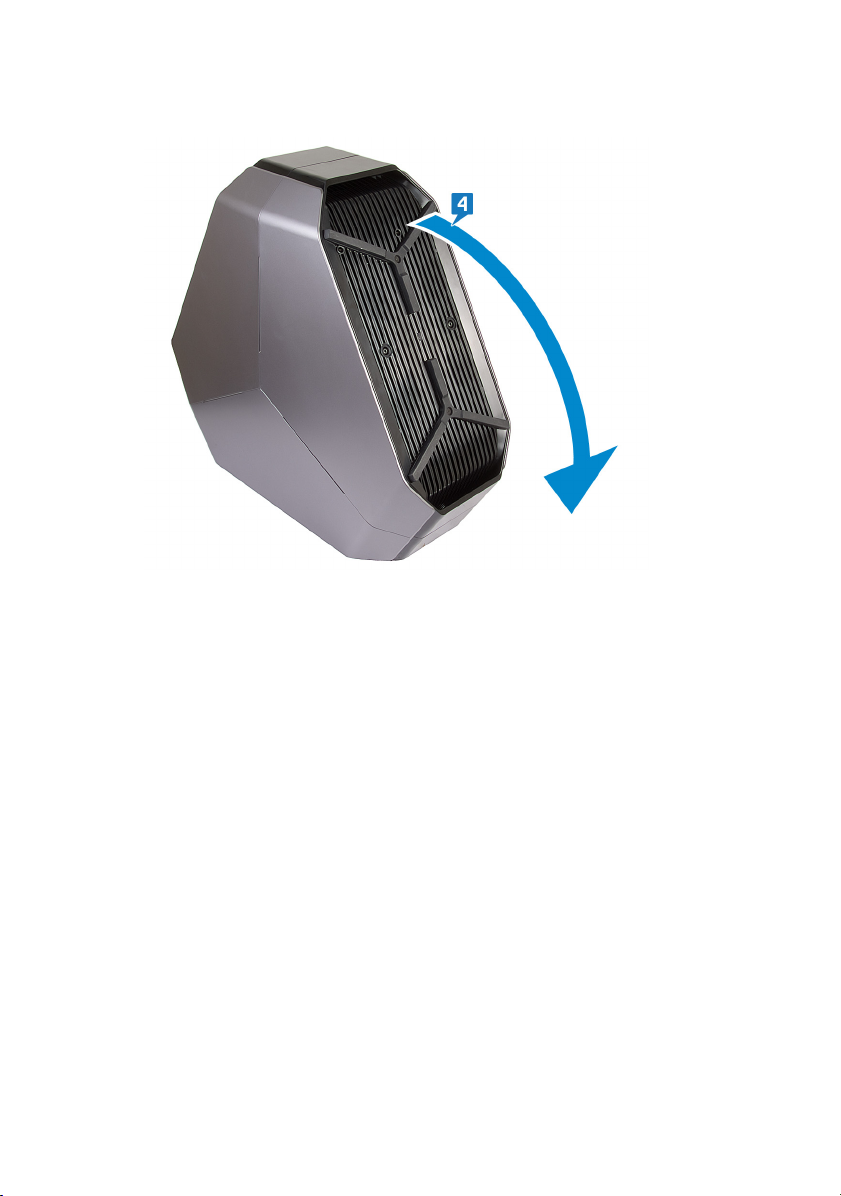
Removing the top fan
WARNING: Before working inside your computer, read the safety
information that shipped with your computer and follow the steps in
Before working inside your computer. After working inside your
computer, follow the instructions in After working inside your computer.
For more safety best practices, see the Regulatory Compliance home
page at
Prerequisites
1 Remove the stability foot.
2 Remove the left and right side-panels. See “Removing the side panels”.
Procedure
1 Lay the chassis on the right side.
2 Disconnect the top-fan cable from the connector on the system board. For
more information on the top-fan cable connector, see “system-board
components”.
3 Remove the screw (#6-32x6) that secures the top fan on the chassis.
www.dell.com/regulatory_compliance.
81
Page 82

4 Pull the release tab away from the chassis, move the top fan towards the right
side and slide the top fan out of the chassis.
82
Page 83

Replacing the top fan
WARNING: Before working inside your computer, read the safety
information that shipped with your computer and follow the steps in
Before working inside your computer. After working inside your
computer, follow the instructions in After working inside your computer.
For more safety best practices, see the Regulatory Compliance home
page at
Procedure
1 Align the tabs on the top fan with the slots on the chassis and slide the fan
until it snaps into position.
2 Replace the screw (#6-32x6) that secures the top fan on the chassis.
3 Connect the top fan cable from the connector on the system board. For more
information on the top fan cable connector, see “system-board components”.
Post-requisites
1 Replace the left and right side-panels. See “Replacing the side panels”.
2 Replace the stability foot.
www.dell.com/regulatory_compliance.
83
Page 84

Removing the logo board
WARNING: Before working inside your computer, read the safety
information that shipped with your computer and follow the steps in
Before working inside your computer. After working inside your
computer, follow the instructions in After working inside your computer.
For more safety best practices, see the Regulatory Compliance home
page at
Prerequisites
1 Remove the stability foot.
2 Remove the left and right side-panels. See “Removing the side panels”.
3 Remove the top fan.
www.dell.com/regulatory_compliance.
84
Page 85

Procedure
NOTE: Note the routing of all cables as you remove them so that you can
route them correctly after you replace the logo board.
1 Disconnect all the cables from the logo board.
2 Remove the screw (#6-32x6) that secures the logo board to the chassis.
85
Page 86

3 Slide the logo board out of the chassis.
4 Remove the six screws (#6-32x6) that secure the logo board to the bracket.
5 Remove the logo board from the bracket.
86
Page 87

Replacing the logo board
WARNING: Before working inside your computer, read the safety
information that shipped with your computer and follow the steps in
Before working inside your computer. After working inside your
computer, follow the instructions in After working inside your computer.
For more safety best practices, see the Regulatory Compliance home
page at
Procedure
1 Align the screw holes on the logo board to the screw holes on the bracket
and slide the logo board in place.
2 Replace the six screws (#6-32x6) that secure the logo board to the bracket.
3 Slide the logo board inside the chassis.
4 Replace the screw (#6-32x6) that secures the logo board to the bracket.
5 Route and connect the respective cables to the logo board.
Post-requisites
1 Replace the top fan.
2 Replace the left and right side-panels. See “Replacing the side panels”.
3 Replace the stability foot.
www.dell.com/regulatory_compliance.
87
Page 88

Removing the solid-state drive
WARNING: Before working inside your computer, read the safety
information that shipped with your computer and follow the steps in
Before working inside your computer. After working inside your
computer, follow the instructions in After working inside your computer.
For more safety best practices, see the Regulatory Compliance home
page at
CAUTION: Solid-state drives are fragile. Exercise care when handling the
solid-state drive.
CAUTION: To avoid data loss, do not remove the solid-state drive while
the computer is in sleep or on state.
Prerequisites
1 Remove the stability foot.
2 Remove the left and right side-panels. See “Removing the side panels”.
Procedure
1 Lay the chassis on the right side.
www.dell.com/regulatory_compliance.
88
Page 89

2 Locate the solid-state drive on the system board.
3 Remove the screw (M2x2.5) that secures the solid-state drive to the system
board.
4 Slide and remove the solid-state drive from the solid-state drive slot on the
system board.
89
Page 90

Replacing the solid-state drive
WARNING: Before working inside your computer, read the safety
information that shipped with your computer and follow the steps in
Before working inside your computer. After working inside your
computer, follow the instructions in After working inside your computer.
For more safety best practices, see the Regulatory Compliance home
page at
CAUTION: Solid-state drives are fragile. Exercise care when handling the
solid-state drive.
Procedure
1 Locate the solid-state drive slot on the system board.
www.dell.com/regulatory_compliance.
2 Align the notch on the solid-state drive with the tab on the solid-state drive
slot and slide the solid-state drive into the solid-state drive slot.
90
Page 91

3 Align the screw hole on the solid-state drive with the screw hole on the
system board.
4 Replace the screw (M2x2.5) that secures the solid-state drive to the system
board.
Post-requisites
1 Replace the left and right side-panels. See “Replacing the side panels”.
2 Replace the stability foot.
91
Page 92

Removing the PCI fan
WARNING: Before working inside your computer, read the safety
information that shipped with your computer and follow the steps in
Before working inside your computer. After working inside your
computer, follow the instructions in After working inside your computer.
For more safety best practices, see the Regulatory Compliance home
page at
Prerequisites
1 Remove the stability foot.
2 Remove the left and right side-panels. See “Removing the side panels”.
Procedure
1 Lay the chassis on the right side.
2 Disconnect the PCI-fan cable from the respective connector on the system
board.
3 Remove the PCI-fan cable from the routing guides on the chassis.
4 Remove the screw (M3x5.25) that secure the PCI fan to the chassis.
www.dell.com/regulatory_compliance.
92
Page 93

5 Slide and remove the PCI fan from the tabs securing it to the chassis.
93
Page 94

Replacing the PCI fan
WARNING: Before working inside your computer, read the safety
information that shipped with your computer and follow the steps in
Before working inside your computer. After working inside your
computer, follow the instructions in After working inside your computer.
For more safety best practices, see the Regulatory Compliance home
page at
Procedure
1 Align the tabs on the PCI-fan with the slots on the chassis and slide the fan
until it snaps into position.
2 Replace the screw (M3x5.25) that secure the PCI fan to the chassis.
3 Connect the PCI-fan cable to the connector on the system board.
Post-requisites
1 Replace the left and right side-panels. See “Replacing the side panels”.
2 Replace the stability foot.
www.dell.com/regulatory_compliance.
94
Page 95

Removing the front-bezel heat sensor cable
WARNING: Before working inside your computer, read the safety
information that shipped with your computer and follow the steps in
Before working inside your computer. After working inside your
computer, follow the instructions in After working inside your computer.
For more safety best practices, see the Regulatory Compliance home
page at
Prerequisites
1 Remove the stability foot.
2 Remove the left and right side-panels. See “Removing the side panels”.
3 Remove the PCI fan.
Procedure
1 Disconnect the front-bezel heat sensor cable from the system board.
2 Remove the front-bezel heat sensor cable from the routing guides on the
chassis.
3 Remove the two screws (M3x5.25) that secure the PCI fan holder to the
chassis.
www.dell.com/regulatory_compliance.
95
Page 96

4 Slide and remove the PCI fan holder from the chassis.
5 Push the release tab and pry the front-bezel heat-sensor cable o the chassis.
96
Page 97

Replacing the front-bezel heatsensor cable
WARNING: Before working inside your computer, read the safety
information that shipped with your computer and follow the steps in
Before working inside your computer. After working inside your
computer, follow the instructions in After working inside your computer.
For more safety best practices, see the Regulatory Compliance home
page at
Procedure
1 Route the front-bezel heat-sensor cable through the bracket.
2 Align the tab on the front-bezel heat-sensor cable on the chassis.
3 Push the release tab on the front-bezel heat-sensor cable and press it into
place.
4 Align and place the PCI fan holder from the chassis.
5 Replace the two screws (M3x5.25) that secure the PCI fan holder to the
chassis.
6 Route the front-bezel heat sensor cable through the routing guides on the
chassis.
7 Connect the front-bezel heat sensor cable to the system board.
www.dell.com/regulatory_compliance.
Post-requisites
1 Replace the PCI fan.
2 Replace the left and right side-panels. See “Replacing the side panels”.
3 Replace the stability foot.
97
Page 98

Removing the processor liquidcooling assembly
WARNING: Before working inside your computer, read the safety
information that shipped with your computer and follow the steps in
Before working inside your computer. After working inside your
computer, follow the instructions in After working inside your computer.
For more safety best practices, see the Regulatory Compliance home
page at
Prerequisites
1 Remove the stability foot.
2 Remove the left and right side-panels. See “Removing the side panels”.
3 Remove the memory modules.
Procedure
WARNING: Despite having a plastic shield, the processor liquid-cooling
assembly may be very hot during normal operation. Ensure that it had
sucient time to cool before you touch it.
CAUTION: To ensure maximum cooling for the processor, do not touch
the heat transfer areas on the processor liquid-cooling assembly. The oils
in your skin can reduce the heat transfer capability of the thermal grease.
www.dell.com/regulatory_compliance.
1 Lay the chassis on the right side.
2 Disconnect the processor liquid-cooling assembly fan cable from the system
board. For more information on the processor liquid-cooling assembly fan
cable connector, see “
3 Disconnect the processor liquid-cooling assembly fan cable from the system
board. For more information on the processor liquid-cooling assembly fan
cable connector, see “system-board components”.
4 In reverse sequential order as indicated on the processor cooling-assembly
pump, loosen the captive screws that secure the processor liquid-cooling
assembly pump to the system board.
98
system-board components”.
Page 99

5 Remove the four screws (M5x10) that secure the processor liquid-cooling
assembly fan to the chassis.
99
Page 100

6 Slide and lift the processor liquid-cooling assembly fan and processor liquid-
cooling assembly pump out of the chassis.
100
 Loading...