

Page 1

OPERATING MANUAL
DIGITAL MASS FLOW
CONTROLLERS
BC-Series
Page 2

Thank you for purchasing your OEM Mass Flow Controllers.
Contact Information
Alicat Scientific
World Headquarters
7641 N Business Park Dr., Tucson, AZ 85743 USA
[email protected] · alicat.com
India
M/s Halma India Pvt. Ltd.
C/O Avire India Pvt. Ltd.
Plot #A-147, Rd. #24
Wagale Ind. Estate,
Thane (West) 400604,
Maharashtra, India
+1 888-290-6060
China & SE Asia
[email protected]
alicat.com.cn
2nd Floor, Block 63, No.
421, Hong Cao Rd,
Shanghai, PRC 200233
+86-21-60407398 ext. 801
This device comes with a NIST traceable
calibration certificate.
This device conforms to the European Union’s
Restriction of Use of Hazardous Substances in
Electrical and Electronic Equipment (RoHS)
Directive 2011/65/EU.
This device complies with the requirements of the
Low Voltage Directive 2014/35/EU and the EMC
Directive 2014/30/EU and carries the CE Marking
accordingly.
· +1 888-290-6060
Europe
Geograaf 24
6921 EW Duiven
The Netherlands
+31 (0) 26 203.1651
This device complies with the requirements of the
European Union’s Waste Electrical & Electronic
Equipment (WEEE) Directive 2002/96/EC
Rev. 0 • 2020-09-25 • DOC-MANUAL-BASIS
2
Page 3

Contents
Getting Started __________________________________________ 4
Mounting _________________________________________ 4
Plumbing _______________________________________________ 5
Process Ports ______________________________________________ 5
Maximum Pressure _________________________________________ 5
Flow Controller Operation ___________________________________ 6
Power and Signal Connections ________________________ 6
RS-232 or RS-485 Digital Signals ______________________ 7
Analog Signals _________________________________ 7
Serial Communication _____________________________________ 8
Establishing Communications _________________________ 8
Serial Terminal Application _________________________ 9
Unit ID and Modbus ID _______________________________ 9
Changing the Baud Rate __________________________ 10
Taring ___________________________________________ 11
Collecting Flow Data _______________________________ 11
Commanding a New Setpoint ________________________ 12
Sending Setpoints as Floating Point Numbers _____________ 12
Sending Setpoints as Integers ______________________ 13
Creating a Setpoint Watchdog ______________________ 13
Flow Averaging ___________________________________ 14
Changing the Gas__________________________________ 14
PID Tuning _______________________________________ 15
Changing Gain Values ___________________________ 15
Tuning the PDF Control Algorithm ____________________ 16
Troubleshooting Valve Performance with PID Tuning ________ 16
Quick Command Guide _____________________________ 17
Modbus/RTU Communication _____________________________ 18
Modbus Registers _________________________________ 18
Configuration Registers __________________________ 19
Data Registers ________________________________ 20
Maintenance ___________________________________________ 21
Cleaning _________________________________________ 21
Recalibration _____________________________________ 21
DIGITAL MASS FLOW CONTROLLER operating manual 3
Page 4
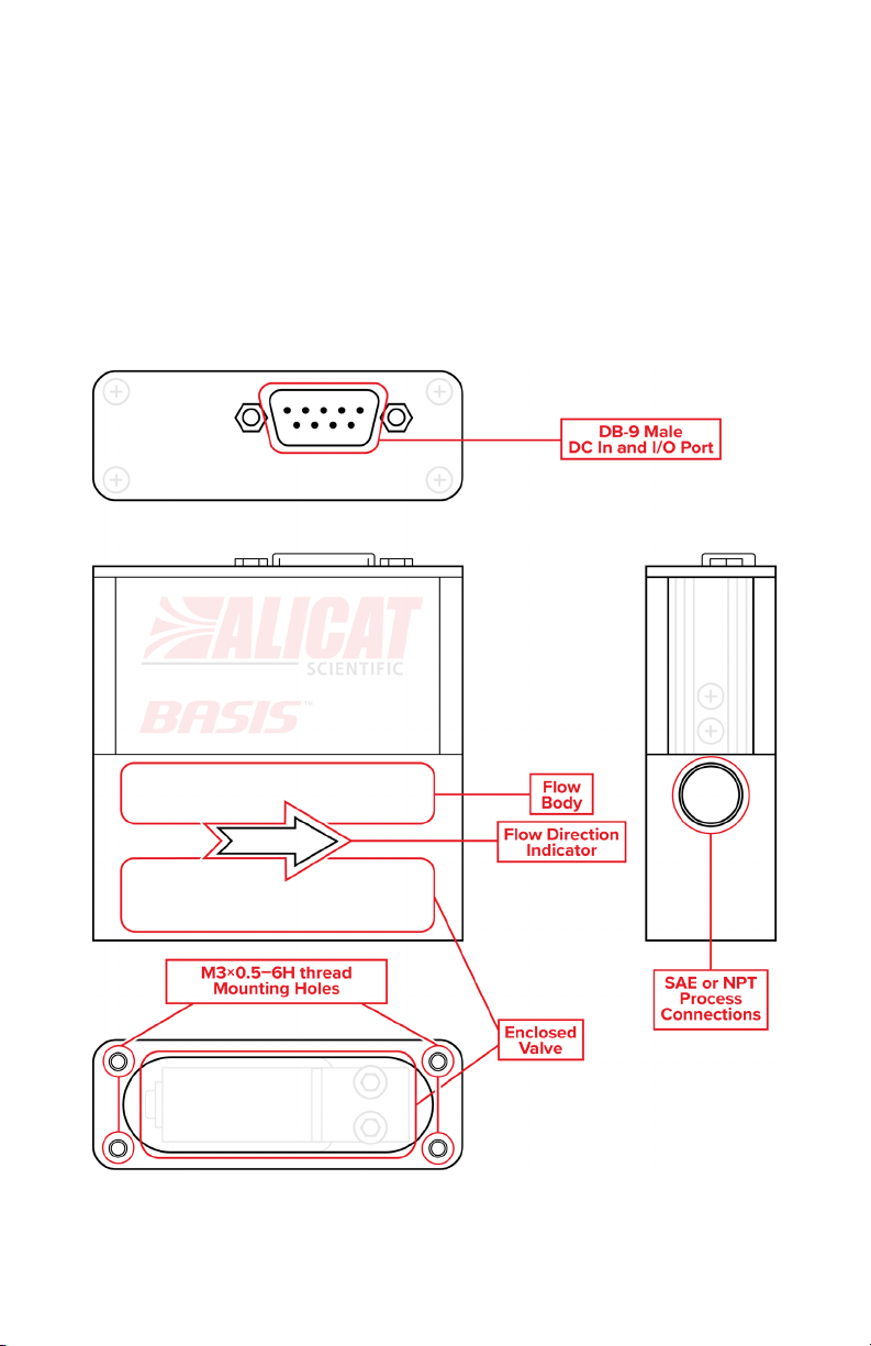
Getting Started
Mounting
No straight runs of pipe are required upstream or downstream of the flow
controller. BASIS (BC-Series) Mass Flow Controllers have mounting holes
on the bottom for convenient mounting to flat panels. The thread size of
these holes is M3. These controllers are position insensitive and can be
mounted in any orientation.
DIGITAL MASS FLOW CONTROLLER operating manual 4
Page 5

connections, as these compounds can cause permanent damage to
Model
Max Common Mode Pressure
BC-C0100
145 PSIG
BC-C1000
145 PSIG
BC-L0020
60 PSIG
Plumbing
Process Ports
Your instrument is shipped with plastic plugs fitted in the port openings. To
lessen the chance of contaminating the flow stream do not remove these
plugs until you are ready to install the device.
• If you are using a fitting that does not have a face seal, use threadsealing Teflon tape to prevent leakage around the port threads, but
do not wrap the first two threads. This will minimize the possibility
of getting tape into the flow stream and flow body.
• If you are using a fitting that has a face seal, there is no need to
apply Teflon tape to the threads.
Warning: Do not use pipe dopes or sealants on the process
!
the controller should they get into the flow stream.
When changing fittings, carefully clean any tape or debris from the port
connections.
Maximum Pressure
Using the flow controller above the maximum specified internal line
pressure will result in permanent damage to the internal sensors. If the line
pressure is above this, please use a pressure regulator upstream of the
flow controller to reduce the pressure to below the maximum internal
pressure. See the chart below for pressure limits.
DIGITAL MASS FLOW CONTROLLER operating manual 5
Page 6

Pin
Function
Cable
1
2
3
4
5
6
7
8
9
Flow Controller Operation
Your flow controller can measure and control flow generated by positive
pressure and/or suction. Connect the controller so that the flow travels in
the same direction as the flow arrow, from left to right, as you look at the
front of the device.
Alicat Scientific BC-Series Mass Flow Controllers incorporate a digital
sensor with a single control valve and circuitry. The integrated control
algorithm measures the mass flow, compares it with the setpoint, and
adjusts the valve accordingly at 400 times per second.
The response time of the system will depend on the operating conditions
and the PID tuning of the device.
Power and Signal Connections
Power must be supplied through the 9-pin D-Sub connector located on top
of your BASIS device. BASIS controllers require a power supply capable of
delivering 10–30 Vdc at 200 mA.
Not Connected Black
Not Connected Brown
Serial RS-232 RX / RS-485 B Input Signal (receive) Red
0–5 Vdc Analog Setpoint Input White
Serial RS-232 TX / RS-485 A Output Signal (send) Yellow
0–5 Vdc Analog Output Signal Green
Power In (as described above) Blue
Ground (common for power, digital communications, and analog signals) Orange
Ground (common for power, digital communications, and analog signals) Orange
Caution: Do not apply power to pins 3, 4, 5, or 6. Permanent
damage can occur.
DIGITAL MASS FLOW CONTROLLER operating manual 6
Page 7

9-Pin Serial Connection
9-Pin Alicat Connection
Pin
Function
Pin
Function
5
Ground
8
Ground
3
Transmit
3
Receive
2
Receive
5
Transmit
RS-232 or RS-485 Digital Signals
To use the RS-232 or RS-485 input signal, connect the RS-232 / RS-485
Output Signal (Pin 5), the RS-232 / RS-485 Input Signal (Pin 3), and Ground
(Pin 8) to your computer serial port as shown below.
Analog Signals
These devices include a primary analog output signal, which is 0–5 Vdc
and linear over its entire range. A zero-flow condition is indicated at
approximately 0.010 Vdc and full scale flow is indicated at 5.0 Vdc. The
output voltage is linear over its entire range. Ground for this signal is
common on pin 8.
DIGITAL MASS FLOW CONTROLLER operating manual 7
Page 8

✓
Serial Communication
The device supports both ASCII-based serial commands and Modbus/RTU
IO over either a RS-232 or RS-485 serial port. The supported physical serial
protocol will be specified in the device model number. Connecting your
flow controller to a computer allows you to log the data that it generates.
This section of the manual shows you how to operate the flow controller
using ASCII commands.
Establishing Communications
After connecting your flow controller using a communications cable, you
will need to establish serial communications through a real or virtual COM
port on your computer or programmable logic computer (PLC).
• If you have connected your device to a serial port, note its COM
port number. This can be found in Windows® Device Manager.
• If you have a serial to USB adapter, plug it into your computer,
ensure the proper driver is installed, and note the COM port
number.
• The controller will be configured with the following settings:
• Baud: 38400 (default; others can be used if the computer, its
software and the controller are set for the same rate)
• Data bits: 8
• Parity: None
• Stop bits: 1
• Flow control: None
Alicat devices use ASCII commands which are easily used in a serial
terminal or integrated into a PLC.
Note: In what follows, indicates an ASCII carriage return (decimal
13, hexadecimal D). Serial commands are not case-sensitive.
DIGITAL MASS FLOW CONTROLLER operating manual 8
Page 9

✓
!
✓
Serial Terminal Application
Alicat’s proprietary Serial Terminal is a preconfigured program for serial
communications that functions much like Windows’ old HyperTerminal
program. Download Serial Terminal at alicat.com/drivers
downloaded, simply run SerialTerminal.exe. Enter the COM port number to
which your device is connected and the baud rate of the flow controller.
The default baud rate is 38400.
Note: Some features of the serial terminal, such as the dump all
command, are not available for BASIS devices. All serial commands
specified in this manual will function as intended.
for free. Once
Unit ID and Modbus ID
The device is addressed with a single letter unit ID from A through Z, with
A being the default. All serial commands must be preceded by the unit ID,
and followed by a carriage return before they take effect. The * character
will address all devices on the serial line and can be used to query the unit
ID, if it is unknown. This should only be used if a single device is connected,
otherwise the responses will be corrupted from multiple devices trying to
write at the same time.
You can change the unit ID by typing:
Change the unit ID: [current unit ID]@= [desired unit ID]
Example: a@=b (changes unit A to unit B)
Warning: Care should be taken not to assign the same unit ID to
more than one device on a single COM port.
This device supports the Modbus/RTU device address from 1–247, and this
is separate from the unit ID. The factory default Modbus ID is 1.
You can read and change the Modbus ID by typing:
Read the Modbus ID: [unit ID]rm
Example: arm (reads Modbus ID on unit A)
Change the Modbus ID: [unit ID]wm=[desired Modbus ID]
Example: awm=7 (changes Modbus ID to 7 on unit A)
Note: When changing to a new Modbus ID, any values above the
maximum of 247 will result in the ID changing to 1.
DIGITAL MASS FLOW CONTROLLER operating manual 9
Page 10

Value
Corresponding Baud Rate
0
4800
1
9600
2
19200
3
38400
4
57600
5
115200
✓
Changing the Baud Rate
BASIS units can communicate over bauds rates of 4800, 9600, 19200,
38400, 57600, or 115200. 38400 is the default baud rate.
You can read the current baud rate as well as change it by typing:
Read the baud rate: [unit ID]rb
Example: arb (reads baud rate on unit A)
Change the baud rate: [unit ID]wb=[desired baud rate,
see table]
Example: awb=2
(changes baud rate on unit A to 19200)
Note: When changing the device’s baud rate, your COM port must
change its own baud rate in time to successfully receive the
response confirming the new baud rate. If it does not, then the baud
rate will change on the device, but the response from the serial
terminal will be incomprehensible. Since the serial terminal is set to
communicate at a specific baud rate during the initial configuration,
you will have to redefine the terminal baud rate to continue
communications. This can be done using the baud
[value] command, where [value] equals the baud rate.
DIGITAL MASS FLOW CONTROLLER operating manual 10
Page 11

A
32.1C
0454.2SCCM
0454.0SP
Air
Unit
Standard
Setpoint
Gas
Taring
Before collecting data, be sure to tare your flow controller. If auto-tare is
enabled, this can be accomplished by providing a setpoint of zero for at
least 2 seconds. Taring flow sets the zero-flow reading and must be done
when no flow is passing through the flow controller:
Tare Flow: [unit ID]v
Example: av (sets flow reading to zero)
To determine if auto-tare is enabled, use the following command:
Read auto-tare setting: [unit ID]re
Example: are
The response from the controller will be
indicates that auto-tare is disabled, and a value of
is enabled. If auto-tare is disabled, then you can enable it using the
following command:
Enable auto-tare: [unit ID]we=1
Example: awe=1 (turn on auto-tare on unit A)
Likewise, auto-tare can be disabled by using the same command but
replacing the
1 with a 0.
ENABLE=value, where a value of 0
1 indicates that auto-tare
Collecting Flow Data
The unit measures flow normally, but will only output data when it is polled.
Polling the flow controller returns a single line of data each time you
request it. To poll the flow controller, simply enter its unit ID.
Poll the device: [unit ID]
Example: a (polls units A)
Whenever you enter this command, a line of data will appear in the
following format:
Temperature
ID
If the device is in exhaust mode, an additional column with an EXH status
code will be present to the right of the gas label column.
DIGITAL MASS FLOW CONTROLLER operating manual 11
(Mass) Flow
Page 12

Valid Values
Meaning
A
0–5 Vdc analog input
D
Digital serial value saved to flash
U
Digital serial value not saved to flash
Commanding a New Setpoint
Before attempting to send setpoints to your BASIS flow controller serially,
confirm that it’s configured to receive serial setpoints. If not, the device will
respond with SETPOINT SOURCE IS ANALOG. This can be done by typing:
Read setpoint source: [unit ID]rs
Example: ars (reads setpoint source on unit A)
Change setpoint source: [unit ID]rs=[desired setpoint source,
see table]
Example: aws=A
(setpoint source on unit A changed to
unsaved serial)
If a digital setpoint is saved to the flash, it will be restored after a power
cycle of the device. The default power-up setpoint is zero. If a non-zero
power-up setpoint is desired, this can be set by giving a setpoint while the
setpoint source is saved to the flash, and then changing the setpoint
source to unsaved.
Warning: If you are frequently changing the setpoint as part of your
system, you can quickly wear out the flash memory. If your process
is like this, it is highly recommended to not save the serial value to
!
the flash.
Sending Setpoints as Floating Point Numbers
This is how to send the desired setpoint value as a floating point number:
New setpoint: [unit ID]s[floating point
number setpoint]
Example: as50 (setpoint of 50.0 SCCM)
DIGITAL MASS FLOW CONTROLLER operating manual 12
Page 13

✓
Sending Setpoints as Integers
In this method, your controller’s full scale range (FS) is represented by a
value of 4000, and a zero setpoint is represented by 0. To calculate your
intended setpoint, use the following formula:
Integer value = 4000 × [desired setpoint] ⁄ [device FS]
Example: A desired setpoint of +760 SCCM on a 1000-SCCM BASIS mass
flow controller with unit ID A is calculated as 4000 x 760/1000 = 3040. The
command to assign a setpoint based on this integer value is:
New setpoint: [unit ID][setpoint as integer
where 4000 is FS]
Example: a3040 (setpoint of 760 SCCM)
If you don’t know your device’s full scale range, you can find out by typing
the following command:
Query Full Scale: [unit ID]f
Example: af (query full scale on unit A)
Creating a Setpoint Watchdog
A setpoint watchdog is a communication watchdog timeout which is usersettable. If no serial communication is received by the device after an
amount of chosen time, the device will force a zero setpoint and close its
valve. The time is set in milliseconds, and valid values are 0–5000. The
commands to set a watchdog and read the current watchdog are as
follows:
Read current watchdog: [unit ID]rw
Example: arw (read watchdog time on unit A)
Set a new watchdog: [unit ID]ww=[new watchdog time, ms]
Example: aww=10 (create watchdog with 10 ms timeout)
Note: The setpoint source must be unsaved digital serial value for
the setpoint watchdog to take effect. If the setpoint source is saved
digital serial value, then the watchdog value can be read and
written, but it will not take effect.
DIGITAL MASS FLOW CONTROLLER operating manual 13
Page 14

Setting
0
1
2
3
4 5 6 7 8
9
Averaging (ms)
0 5 10
20
40
80
160
320
640
1280
✓
Gas Number
0 1 2 3 4 5 6
7
Gas (long name)
Air
Argon
Carbon
Dioxide
Nitrogen
Oxygen
Nitrous
Oxide
Hydrogen
Helium
Gas (short name)
Air
Ar
CO2
N2
O2
N2O
H2
He
✓
Flow Averaging
Flow averaging governs how the flow sensor reports its data. The higher
the flow averaging setting, the greater a smoothing effect will be applied.
This is most useful on rapidly-fluctuating flow readings. Allowed values are
integers from 0–9, which correspond to the following settings:
Read current averaging: [unit ID]ra
Example: ara (read averaging on unit A)
Set new averaging values: [unit ID]wa=[integer value]
Example: awa=5
(set averaging on unit A to 80 ms)
Changing the Gas
BASIS units calibrated with air have built-in correction equations that allow
flow with up to 8 different gases. To reconfigure your flow controller to flow
a different gas, look up its Gas Number in the table below. Then type:
Change the gas: [unit ID]g[gas number]
Example 1: ag2 (reconfigures to flow CO
Example 2: ag6 (reconfigures to flow H
Note: BASIS units with a 1000 SCCM full scale that are calibrated to
carbon dioxide or nitrous oxide are limited to a maximum flow rate
of 750 SCCM instead of 1000 SCCM due to the correction factor
equations used for these gases.
Note: Units that are calibrated with Hydrogen or Helium can only
function with that gas.
)
2
)
2
DIGITAL MASS FLOW CONTROLLER operating manual 14
Page 15

PID Tuning
Your flow controller uses a closed-loop algorithm to determine how to
actuate its valve in order to achieve the commanded setpoint. We have
tuned these settings to work for most operating conditions, but sometimes
your process requires on-site adjustments to maintain optimal control
performance. If you encounter issues with control stability, oscillation, or
speed of response, fine-tuning your closed-loop control may help.
Changing Gain Values
Before you begin any PID tuning, it’s a good idea to write down your
current values so you can return to the factory settings if necessary:
Read I value: [unit ID]ry
Example: ary (read current I value on unit A)
Read P value: [unit ID]rx
Example: arx (read current P value on unit A)
To write new I and P values to the controller, type:
Change I value: [unit ID]wy=[desired I value]
Example: awy=150 (change I value to 150 on unit A)
Change P value: [unit ID]wx=[desired P value]
Example: awx=450 (change P value to 450 on unit A)
DIGITAL MASS FLOW CONTROLLER operating manual 15
Page 16

✓
Tuning the PDF Control Algorithm
Alicat’s control algorithm employs pseudo-derivative feedback (PDF)
control, which uses two editable variables:
• The larger the integral (I) gain, the faster the controller will correct for
offsets based on the size of the errors and amount of time they have
occurred.
• The larger the proportional (P) gain, the slower the controller will correct
errors between the commanded setpoint and the measured process value.
Troubleshooting Valve Performance with PID Tuning
The following issues can often be resolved by adjusting the PID gain values
for your flow controller.
Fast oscillation around setpoint / Overshooting setpoint
• Reduce the integral gain in decrements of 10%.
Delayed or unattained setpoint
• Increase the integral gain in increments of 10%, and then decrease
the P gain by small amounts to fine-tune.
Note: Valve tuning can be complex. Please give us a call, and we’ll
be happy to guide you through the process. See page 2
.
DIGITAL MASS FLOW CONTROLLER operating manual 16
Page 17

✓
Quick Command Guide
Note: Serial commands are not case-sensitive. For simplicity, we
assume that the unit ID of the flow controller when not streaming is a
in the listing that follows.
Change unit ID: a@=[desired unit ID]
Change Modbus ID: awm=[desired Modbus ID]
Change baud rate: awb=[baud rate, see page 10]
Poll the live data frame: a
Tare flow: av
Flow averaging: awa=[value, see page 14]
Set setpoint source: aws=[setpoint source, see page 12]
New setpoint: as[setpoint as floating point #]
New setpoint: a[setpoint as integer
where 4000 is full scale]
Query full scale: af
Create setpoint watchdog: aww=[desired watchdog time in ms]
Change the gas: ag[gas number, see table on page 14]
Exhaust*: ae
Cancel exhaust: ac
Firmware version: arv
Serial number: arn
Change I Gain: awy=[desired gain value]
Change P Gain: awx=[desired gain value]
* When the valve is in exhaust mode, the EXH status code will appear to the right
of the gas in the data frame whenever the device is polled.
If you have need of more advanced serial communication commands,
please contact support (page 2
DIGITAL MASS FLOW CONTROLLER operating manual 17
).
Page 18

Function Code
Function
3
Read holding register
6
Write single register
16
Write multiple registers
✓
✓
✓
Modbus/RTU Communication
All BASIS devices support input and output using the Modbus/RTU
protocol. The following Modbus commands are supported:
Note: All function codes and registers listed in this manual
are base 10.
Modbus Registers
BASIS devices use the Modbus PLC numbering convention such that all
registers begin at index 0. The table below lists the data addresses of each
holder register, where the register number is offset by 1 from the address.
For example, holding register 1 will have a data address of zero.
All 32-bit values are handled in consecutive Modbus registers in big-endian
format. This means bits 31:16 are in the lower numbered Modbus register
and bits 15:0 are in the higher register. All floating-point values are IEEE 32bit floats.
Note: All values are unsigned shorts (2-bytes),
unless otherwise specified.
Note: Many addresses on the table on page 19 are applicable only
to BASIS firmware greater than 2.4.0. If you have an older BASIS
unit, please contact Alicat for information on legacy data addresses.
DIGITAL MASS FLOW CONTROLLER operating manual 18
Page 19

Data Address
Access
Description
21
25
26
39
40
45
46
47
49
52
512
513
514
5000) in milliseconds. If zero, then the
516
519
520
Configuration Registers
–31
–48
R/W
R
R
W
R/W
R/W
R/W
R
R
R/W
R/W
The baud rate. See baud table on page 10 for valid values.
The firmware version. This is encoded as 256 × a + 16 × b + c
where the version is Va.b.c. For example, V2.1.3 would read as 2
× 256 + 1 × 16 + 3 = 531.
The serial number. This is a string of characters, with two
characters per register.
Perform a tare. To do this, write 43605 (0xAA55) to this register.
The time constant for flow averaging, as an integer from 0–9.
(
value
Time (ms) ≈ 2.5 × 2
Modbus Device ID (1–247)
Serial unit ID in ASCII (e.g. A=65)
The full scale of the device (4-byte unsigned integer) in current
engineering units. The full scale can be calculated using:
Full Scale = value/1000
The flow engineering units
0: SCCM
1: SLPM
The STP temperature. Valid values are 0–3000 (0–30°C)
STP Temperature (°C) = value / 100
Exhaust mode
0: Valve under PD control
1: Valve in full-open exhaust
)
Exhaust valve-drive percentage
DIGITAL MASS FLOW CONTROLLER operating manual 19
R/W
R/W
R/W
R/W
R/W
Valve-drive is an integer such that 0 is fully closed and 10000 is
full open. Only applicable if the valve is in exhaust mode.
The setpoint watchdog (0–
watchdog is disabled.
Setpoint source
0: Analog input
1: Digital serial value saved to flash
2: Digital serial value not saved to flash
The proportional (P) gain value as an integer (0–65534)
The integral (I) gain value as an integer (0–65534)
Page 20

Data Address
Access
Description
2048
2049
2050
2052
The instantaneous valve drive. The valve drive indicates by
2053
Setpoint (4-byte signed integer) in flow units. The setpoint
Data Registers
–2051
–2054
R/W
R
R
R
R/W
The currently selected gas, returned as the gas number.
See gas table on page 14 to view available gases.
Temperature in degrees Celsius.
Value is presented as hundredths of a degree. For example,
2850 = 28.5°C
Current mass flow rate (4-byte signed integer) in flow units.
Register 2050 is the MSB (31:16), register 2051 is the LSB
(15:0). The mass flow can be calculated using the following
formula:
Flow = value/1000
how much the valve is open.
Valve drive (%) = value/100
can be calculated as: Setpoint = value/1000.
The setpoint is updated when the lower register is written.
DIGITAL MASS FLOW CONTROLLER operating manual 20
Page 21

Maintenance
Cleaning
This device requires minimal maintenance. If necessary, the outside of the
device can be cleaned with a soft dry cloth. Avoid excess moisture or
solvents.
The single most important thing that affects the life and accuracy of these
devices is the quality of the gas being measured. The instruments are
designed to measure clean, dry, non-corrosive gases.
Recalibration
The BASIS series is an OEM product calibrated to NIST traceable standards
at the time of manufacture. As an OEM device, there is not a factory
recommended periodic recalibration cycle. Recalibration can be requested
at the user’s discretion/requirement. A recalibration can be requested with
your serial number at alicat.com/service
For repair, recalibration, or recycling of this product
.
contact us (page 2
).
Technical Specifications and Dimensional Drawings
Please visit alicat.com/specs to find complete operating specifications and
dimensional drawings.
DIGITAL MASS FLOW CONTROLLER operating manual 21
 Loading...