

Page 1
www.alfatronelectronics.com
ALFATRON ELECTRONICS GmbH GERMANY
ALF-IP6
Wallplate Control Panel- 6 buttons
All Rights Reserved
Version: ALF-IP6_2021V1.1
Page 2

ALF-IP6
Preface
Read this user manual carefully before using the product. Pictures are shown in this
manual for reference only, different models and specifications are subject to real
product.
This manual is only for operation instruction, please contact the local distributor for
maintenance assistance. The functions described in this version were updated January
2018. In the constant effort to improve the product, we reserve the right to make
functions or parameters changes without notice or obligation. Please refer to the dealers
for the latest details.
FCC Statement
This equipment generates, uses, and can radiate radio frequency energy and, if not
installed and used in accordance with the instructions, may cause harmful interference
to radio communications. It has been tested and found to comply with the limits for a
Class B digital device, pursuant to part 15 of the FCC Rules. These limits are designed
to provide reasonable protection against harmful interference in a commercial
installation.
Operation of this equipment in a residential area is likely to cause interference, in which
case the user at their own expense will be required to take whatever measures may be
necessary to correct the interference.
Any changes or modifications not expressly approved by the manufacture would void
the user’s authority to operate the equipment.
Page 3

ALF-IP6
SAFETY PRECAUTIONS
To ensure the best from this product, please read all instructions carefully before using
the device. Save this manual for further reference.
Unpack the equipment carefully and save the original box and packing material for
possible future shipment.
Follow basic safety precautions to reduce the risk of fire, electrical shock, and injury
to persons.
Do not dismantle the housing or modify the module. It may result in electrical shock
or burn.
Using supplies or parts not meeting the products’ specifications may cause damage,
deterioration, or malfunction.
Refer all servicing to qualified service personnel.
To prevent fire or shock hazard, do not expose the unit to rain, moisture or install
this product near water.
Do not put any heavy items on the extension cable in case of extrusion.
Do not remove the housing of the device as opening or removing housing may
expose you to dangerous voltage or other hazards.
Install the device in a place with fine ventilation to avoid damage caused by
overheat.
Keep the module away from liquids.
Spillage into the housing may result in fire, electrical shock, or equipment damage.
If an object or liquid falls or spills onto the housing, unplug the module immediately.
Do not twist or forcefully pull the ends of the optical cable. It can cause malfunction.
Do not use liquid or aerosol cleaners to clean this unit. Always unplug the power to
the device before cleaning.
Unplug the power cord when left unused for a long period of time.
Information on disposal for scrapped devices: do not burn or mix with general
household waste, please treat as normal electrical waste.
Page 4

ALF-IP6
Contents
1. Introduction ................................................................................................................. 1
1.1 Introduction to ALF-IP6 ...................................................................................... 1
1.2 Features ............................................................................................................ 1
1.3 Package List ...................................................................................................... 1
2. Panel Description ........................................................................................................ 1
3. System Connection ..................................................................................................... 3
4. Control Panel Software ............................................................................................... 4
4.1 Basic Setting ...................................................................................................... 4
4.2 Panel Set ........................................................................................................... 7
4.3 Action List .......................................................................................................... 8
4.4 Event setting ...................................................................................................... 9
4.4.1 RS232 Setting ......................................................................................... 9
4.4.2 IR Setting ............................................................................................... 11
4.4.3 TCP/IP Setting ....................................................................................... 14
4.4.4 Delay setting .......................................................................................... 15
4.4.5 Compare Setting .................................................................................... 16
4.4.6 LED setting ............................................................................................ 17
4.4.7 Toggle Setting ........................................................................................ 18
4.5 Event List ......................................................................................................... 20
5. Specification ............................................................................................................. 21
6. Panel Drawing .......................................................................................................... 22
7. Troubleshooting & Maintenance ............................................................................... 23
8. After-Sales…………………………………………………………………………………..24
9. Warranty…………………………………………………………………………………….25
Page 5

ALF-IP6
1 x ALF-IP6
2 x Screw (M4*35)
1 x Power adapter (12VDC 1A)
3 x 2-Pin Pluggable terminal blocks
1 x 3-Pin Pluggable terminal block
1 x 5-Pin Pluggable terminal block
1 x Button label
6 x Button caps
1 x User Manual
1. Introduction
1.1 Introduction to ALF-IP6
The Alfatron ALF-IP6 Wallplate Control Panel has three built-in programmable RS232
connectors and two Infrared (IR) connectors.
The Programmable Control Panel can fully control the compatible switches, as well as
third-party devices such as a matrix switcher, compact scaler switcher, projectors,
screens, etc. Use the device for presentations in showrooms, classrooms, and
boardrooms.
1.2 Features
Each button can be programmed to send bi-direction RS232 commands
simultaneously to control third party devices.
Each button can be programmed to send the IR codes simultaneously to control the
third-party devices and support IR code learning function.
The unit may be programmed through the Ethernet port, via the Control Software.
Crystal and backlit buttons with easy user-friendly customizable changeable labels.
The backlit brightness is controllable.
Dimension: 70mm long and 41mm wide.
1.3 Package List
Note: Please confirm if the product and the accessories are all included, if not, please
contact your local agent.
1
Page 6
ALF-IP6
No.
Name
Description
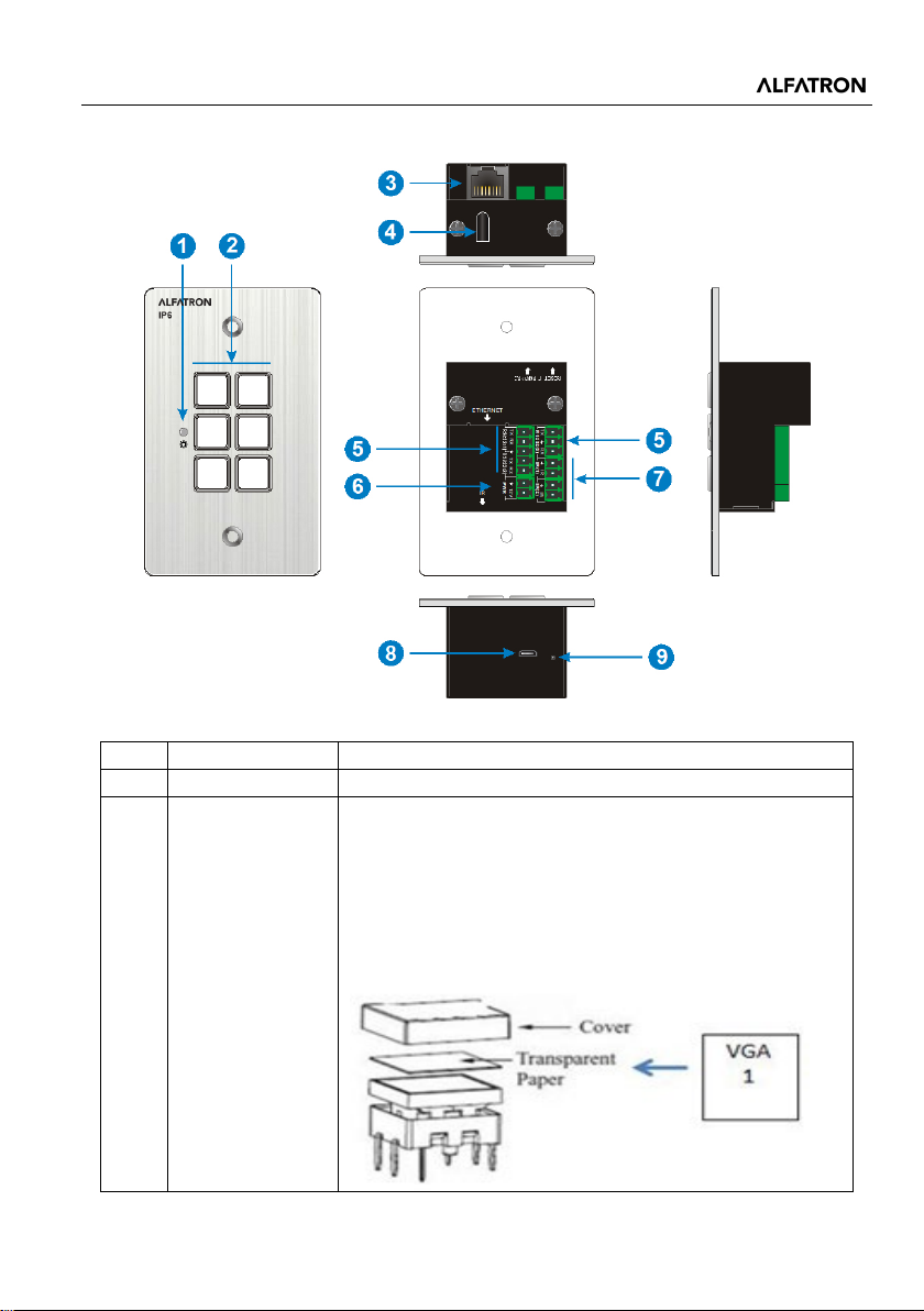
1
Power LED
Illuminates red when powered on.
Six crystal and luminescent programmable buttons:
2. Panel Description
Each button can be programed with the Control Panel
Software.
Each label within a button can be easily changed.
2 Button
Simply select the label you need and change it as
shown below:
1
Page 7
ALF-IP6
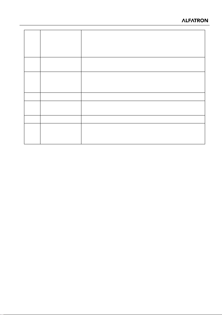
Receives and learns the IR code to build the IR
Connects with 12V DC power adaptor.
8
FIRMWARE
Micro USB port for firmware updating.
Long-press this button for three (3) seconds until the
3 ETHERNET
RJ45 connector. Connects with a PC to run the Control
Panel Software to customize button control. After setting
button functions, the port can be connected to a
third-party device to control it via buttons.
4 IR Sensor
5
6 PWR (12V)
7 IR (1) ~ IR (2)
9 RESET
RS232(1) ~
RS232(3)
database.
Tot a l of three RS232 ports. Connect to third-party
devices which need to be controlled via the Control
Panel Software.
Two IR output ports. Connects with IR Emitter to control
other devices via the Control Panel Software.
power LED goes out to restore factory default. When the
LED lights up, the reset is successful.
2
Page 8
ALF-IP6
TX RX
RS232(3)
IR(1) IR(2)
TX RX
12V
PWR
TX RX
ETHERN ET
IR
IR
IR
IR Remote
IR Emitter
IR Emitter
IR:
TCP/IP:
RS232 :
1
Wireless Route
3. System Connection
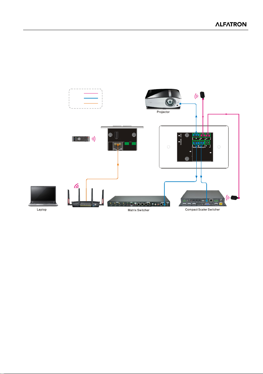
The ALF-IP6 can activate different ports at the same time. This means every button can
send RS232 commands, IP and IR codes at the same time.
The system diagram as below:
System Diagram
1) Connect the ALF-IP6 to the LAN port of a Wireless Router or control device (PC) to
the ETHERNET port.
2) Connect the third-party device (Matrix Switchers, Compact Scaler Switchers, or a
3) Connect the IR Emitters to IR (1) ~ IR (2) ports.
Projector) that need to be controlled to the RS232 (1) ~ RS232 (3) ports.
3
Page 9
ALF-IP6
Same network
switcher
4. Control Panel Software
4.1 Basic Setting
You can use Control Panel Software to easily set functions for each button.
1) Connect the control PC to the ETHERNET port.
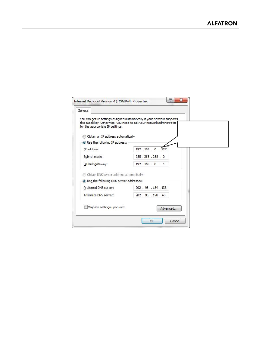
2) The default IP of the ALF-IP6 wallplate is 192.168.0.178 (modifiable); the control
PC should have its network segment the same as the ALF-IP6’s.
segment as the
3) Install / uninstall Control Panel Software:
Install: Copy the software file to the computer connected with ALF-IP6
Uninstall: Delete all the software files in corresponding file path.
Modify the IP of the PC
4
Page 10
ALF-IP6
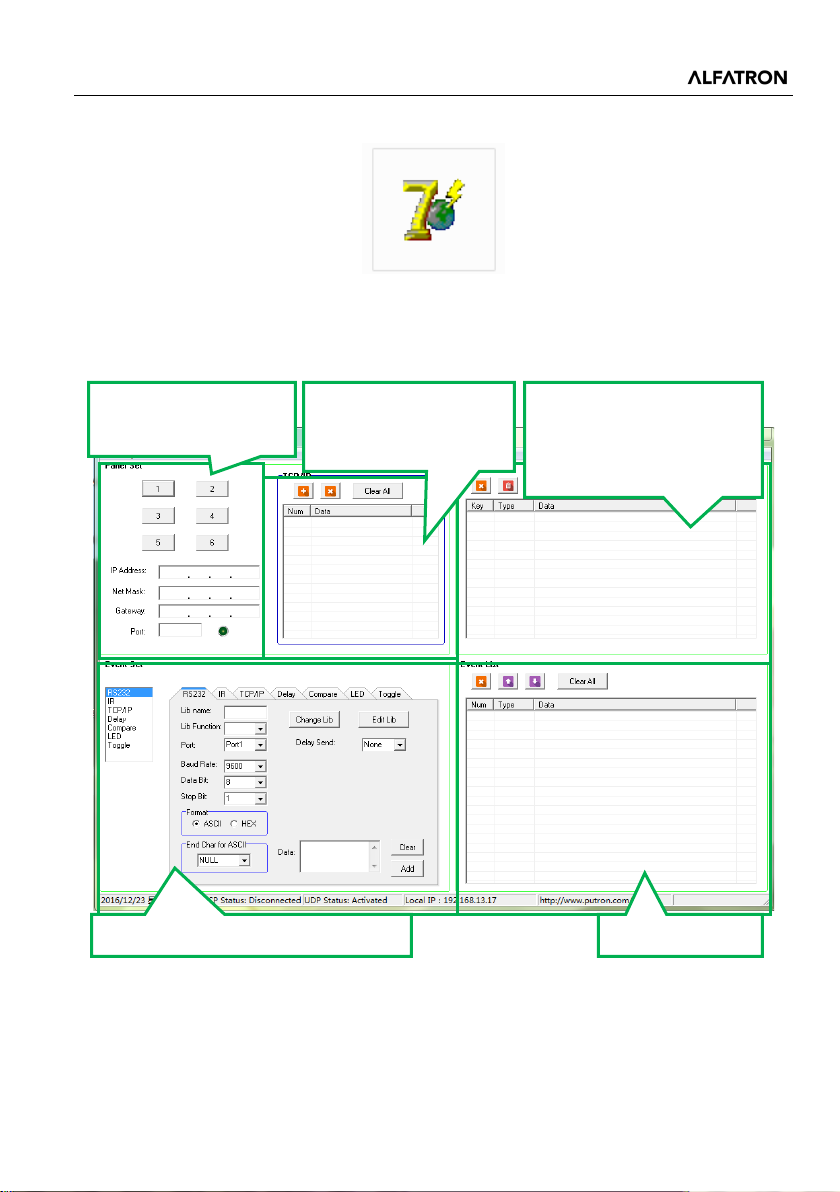
Panel Set: Click “1~6”
Show IP addresses of
in LAN.
Show all key actions, and
events.
Set events for the selected action.
Show all events.
4) Double-click the below software icon to run this software:
The main window of the Control Panel Software has five parts:
Panel Set, TCP/IP, Action List, Event Set and Event List.
The main window of the Control Panel Software is shown as below:
to set key action
all connected devices
any action can be
selected for setting
5
Page 11

ALF-IP6
The header of the main window has four titles including File, System, Connection, and
Help.
Click “File” → “Save” to save the current setting.
Click “File” → “Save as” to save all configuration information as a file.
Click “File” → “Open” to recall a configuration file.
Click “System” → “Version” to query the current software version.
Click “System” → “Message” to query the Link Status, Machine Type, Software
Version, IP Information, and MAC address.
Click “File” → “Software Update”
Hold down the “3” button and power on the system until the button lights up to
enable update mode → Open upgrade Web page (http://192.168.0.178:4001/) on
IE → Type User ID (admin) and Password (123456) → upload update file →
Click “Upload”
Click “System” → “Factory Defaults” to restore to factory default.
Click “Connection” → “TCP/IP” → “Reconnect” to reconnect all ALF-IP6’s.
Click “Connection” → “Upload” → to load the MCU information from the selected
ALF-IP6 to the control software.
Click “Connection” → “Download” → to download the current setting information to
the selected ALF-IP6 from the control software.
6
Page 12
ALF-IP6
4.2 Panel Set
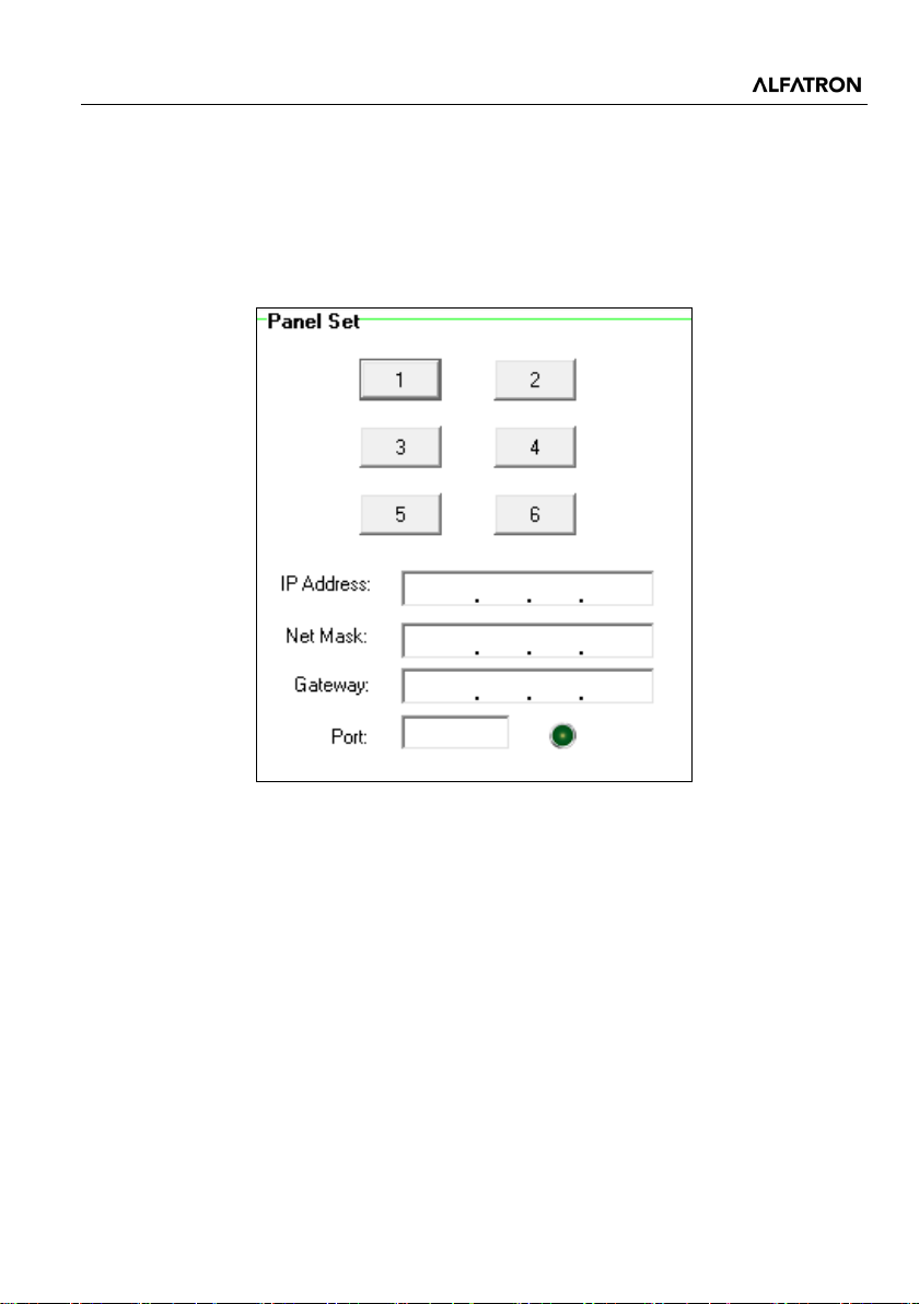
Tot a l of six customizable buttons on the front panel can be set via this software. Add a
button action to show the action list, then add events to ensure this action will execute
the events.
How to set up a button example:
7
Page 13
ALF-IP6
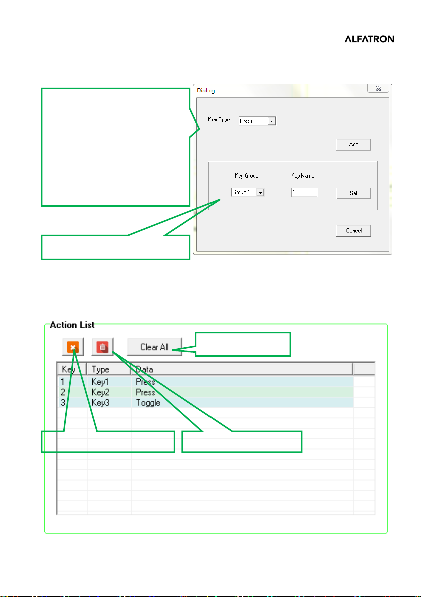
Key Type:
execute different events.
Built key group for LED setting.
Delete the selected action.
Delete all invalid actions.
Buttons 1 through 6, correspond to the physical buttons on ALF-IP6. Click on button 1,
the following dialog window will pop up:
1. Press: Execute events when
button is pressed.
2. Release: Execute events when
button is released.
3. Toggle: The button can be
regarded as composite key,
press the button twice to
4.3 Action List
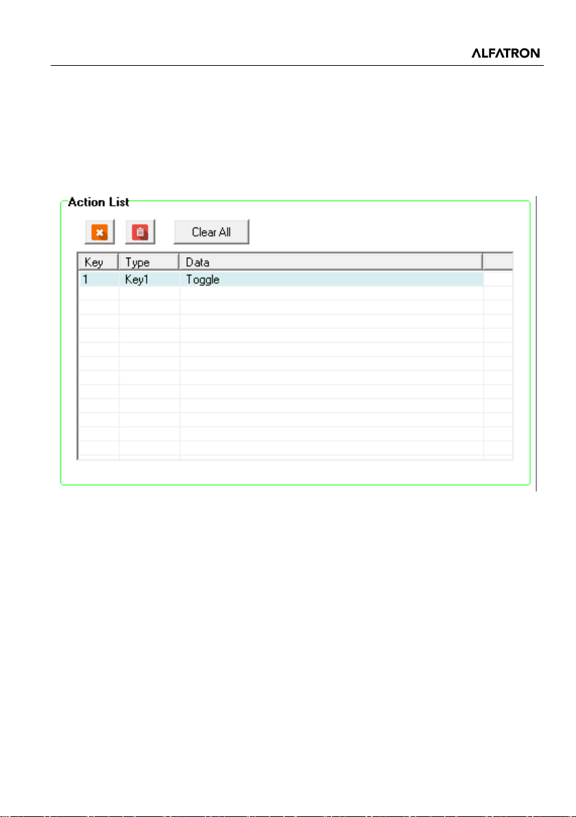
All Panel Set actions will be shown on the action list and available actions must be
added to the list. The action list is as the picture below:
Empty all actions.
8
Page 14
ALF-IP6
4.4 Event setting
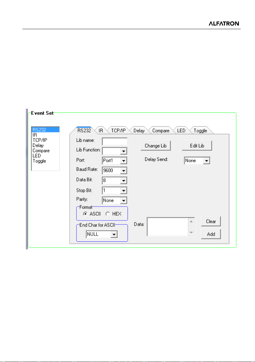
Event Set window includes RS232, IR, TCP/IP, Delay, Compare, LED, and Toggle
settings. Before setting events, an action must be added first. The following introduction
is about how to set events for each action.
4.4.1 RS232 Setting
This item is used for setting the events for RS232 (1) ~ RS232 (3) ports. Click “RS232”,
it will show as below:
Operation procedure:
1) Select the button action in action list.
2) Set the “Lib name” and “Lib Function”. This is an optional function, not compulsory.
3) Select the RS232 port. The port must be same as model setting, otherwise the
event cannot be added.
4) Confirm and set the baud rate, data bit, stop bit, and parity.
5) Enter RS232 command in data box, then press “add” to save setting.
9
Page 15
ALF-IP6
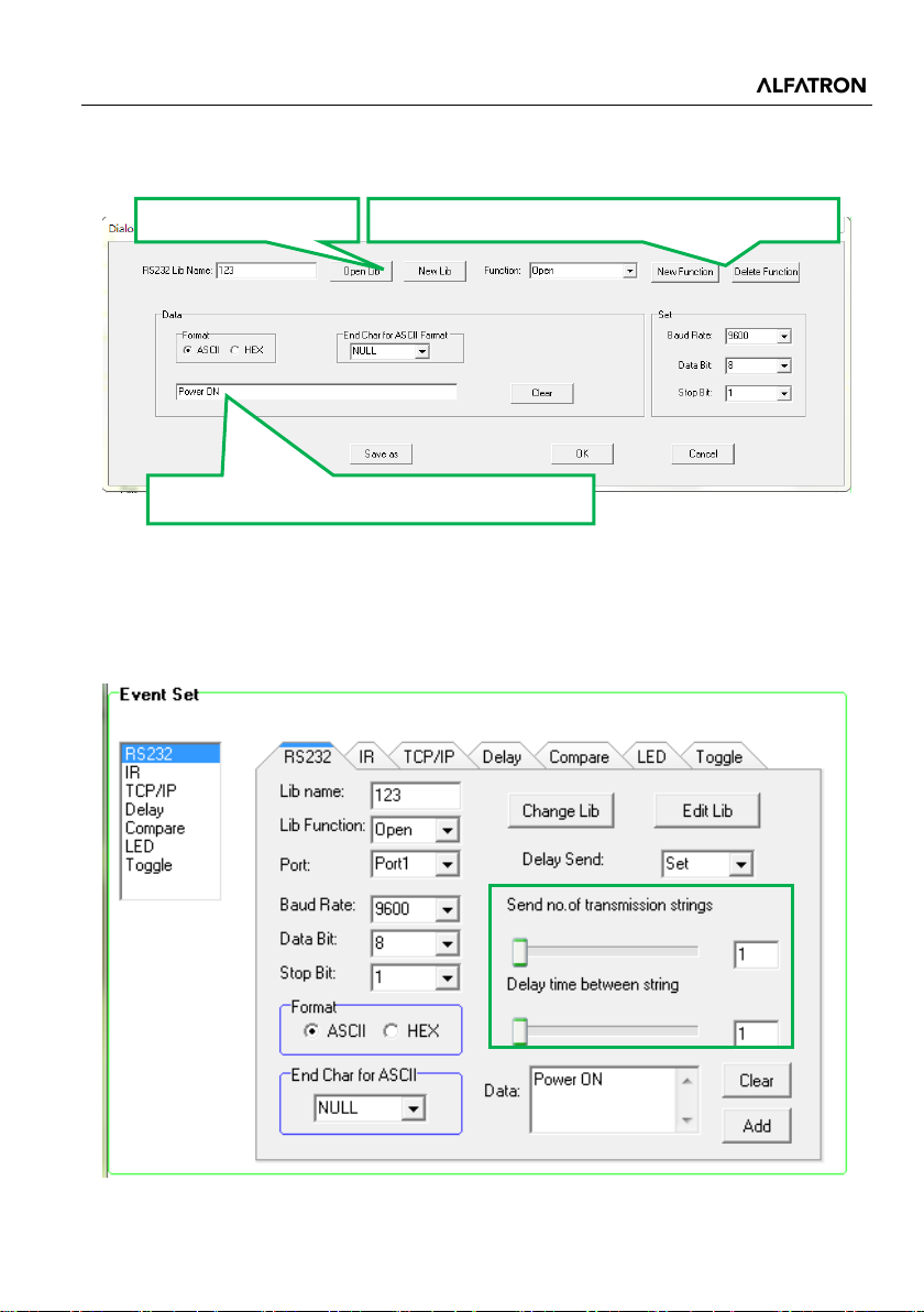
Create/delete the function name of the command
Open/create a library
6) The RS232 data also can be selected from the library. Click “Change Lib” to select
a library file and open it, or, click “Edit Lib” to create a library file as below:
Note: Once set up, please press “Save” to save the edit or “Save as” to save as a file,
and then press “OK”.
7) There are two “Delay Send”: Set and None. When selecting “Set”, the number of
Enter the RS232 command for device control.
sending strings and the delay time between strings can be set.
10
Page 16
ALF-IP6
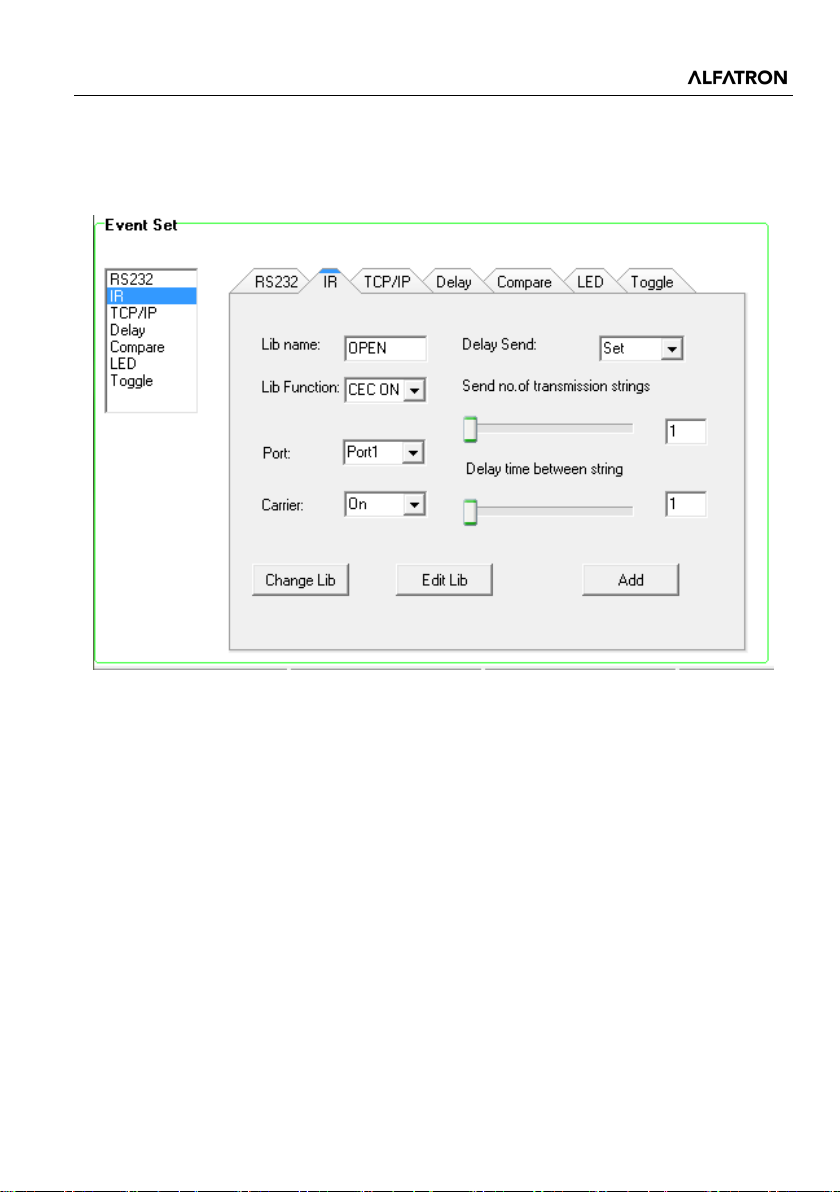
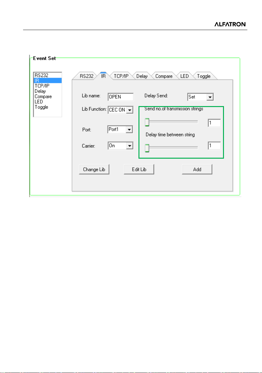
4.4.2 IR Setting
This item is used for setting the events for IR (1) ~ IR (2) ports. Click “IR”, it will display
as follows:
11
Page 17
ALF-IP6
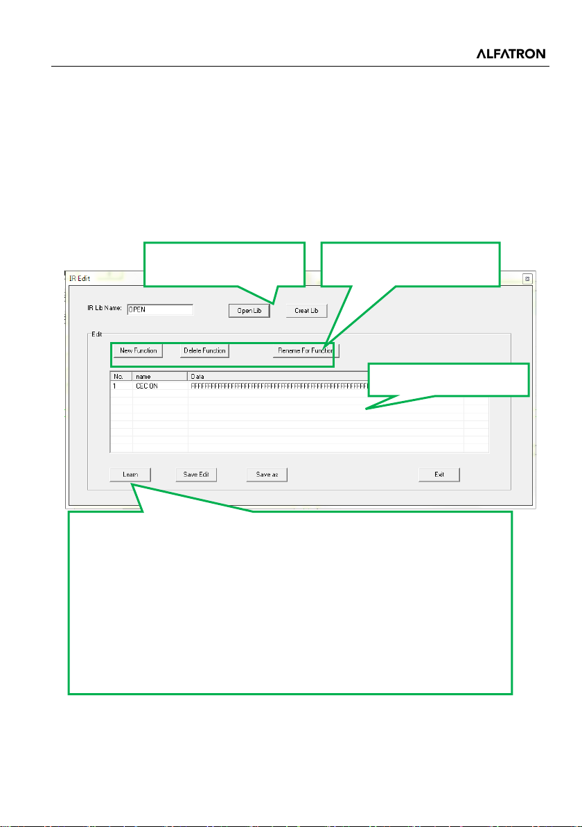
operation within 3 seconds.
function name of the IR data
Show IR data.
Operation procedure:
1) Select the button action in action list.
2) Set the “Lib name” and “Lib Function”. It is an optional function, not compulsory.
3) Select the IR port. The port must be the same as the model setting, or the event
cannot be added.
4) Set the IR carrier mode: On/Off
5) The IR data needs to be selected from library. Click “Change Lib” to select a library
file and open it. Click “Edit Lib” to create or edit a library file as below:
Create/open a library
Create/delete/rename the
IR Learning Procedure:
1. Click “learn” to enter IR learning mode.
2. Put the IR Remote close to the IR sensor of the ALF-IP6.
3. Press any button on the IR Remote to send the IR code to the IR sensor,
Note: Once set up, please press “Save Edit” to save the edit or “Save as” to save as a
file, and then press “OK”.
it will then refresh the IR data.
4. Following the above steps enables the device to learn any function of
the remote buttons.
Note: The IR learning mode will be exited automatically if there is no
12
Page 18
ALF-IP6
6) There are two “Delay Send”: Set and None. When selecting “Set”, the number of
sending strings and the delay time between strings can be set.
13
Page 19
ALF-IP6
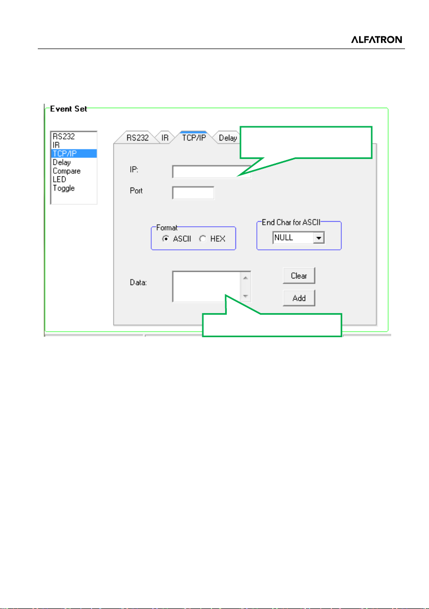
Type the IP address of the
device that needs to be set.
Type in the control command.
4.4.3 TCP/IP Setting
The TCP/IP port supports pass-through function. You can set the events for different IP
port via commands.
14
Page 20
ALF-IP6
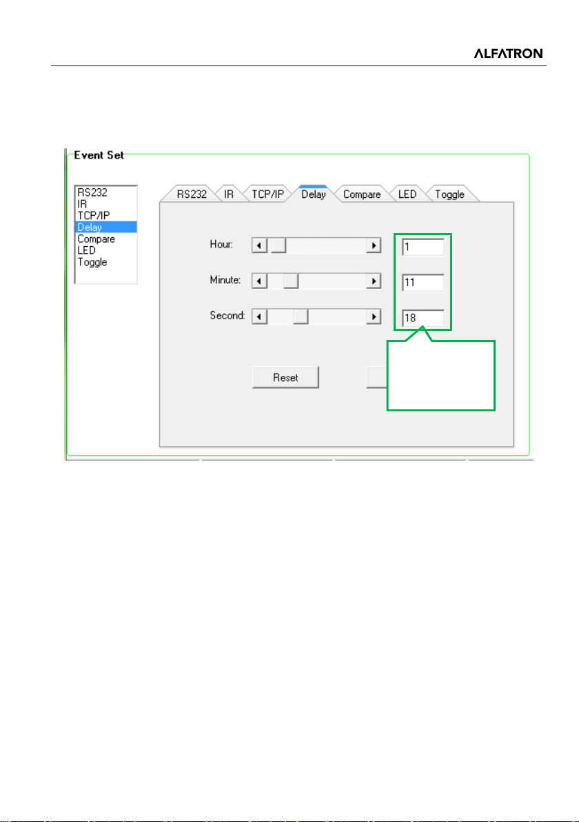
Hour: 0~24
Second: 0~60
4.4.4 Delay setting
This item is to add a delay between two events; when one event is completed, it will
delay a certain time then start the next event. The delay setting is as picture below:
Minute: 0~60
15
Page 21
ALF-IP6
4.4.5 Compare Setting
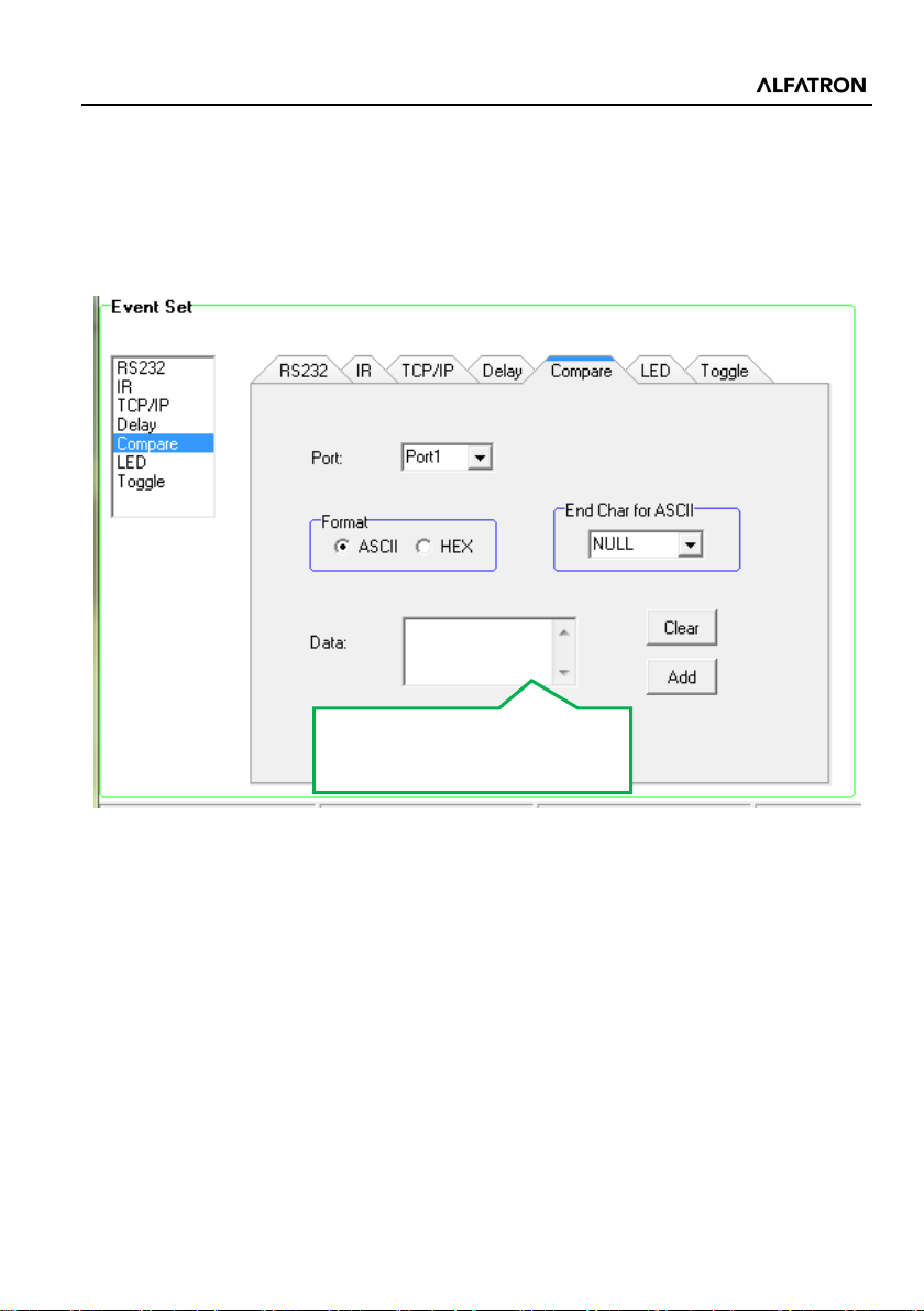
This item is used for comparing the feedback of the RS232 commands. When the
ALF-IP6 sends an RS232 command to the controlled device, the device will send
feedback. If the correct feedback is added in the data, the ALF-IP6 will compare it with
the feedback received from controlled device, to verify whether the command is working
or not. The “Compare” setting is as below:
Enter the compare commands,
DO NOT miss any characters.
Operation procedure:
1) Select the button action in the action list.
2) Select the RS232 port. The port must be same as the model setting, or the event
cannot be added.
3) Set the command format ASCII or Hex, if selecting ASCII then the end character
must be set.
4) Enter the RS232 command which needs to be compared in data box, then press
“add” to save the setting.
5) Add an event that the LED lights up to indicate the comparative result.
6) For events in one event list, a priority is followed, from top to bottom, so that the
compare function can be used in action which has three or more events.
16
Page 22
ALF-IP6
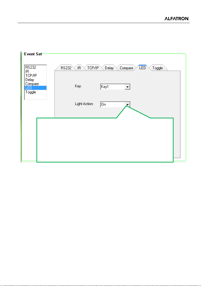
1. On: Turn on the LED of button 1
4.4.6 LED setting
This item is used for setting the button LEDs in ALF-IP6 to turn on or off. The setting is
as follows:
2. Off: Turn off the LED of button 1
3. On/Other Off: Turn on the LED of button 1 and turn off the
others.
4. On/Group Off: Turn on the LED of button 1 and turn off the
others in same group.
17
Page 23
ALF-IP6
4.4.7 Toggle Setting
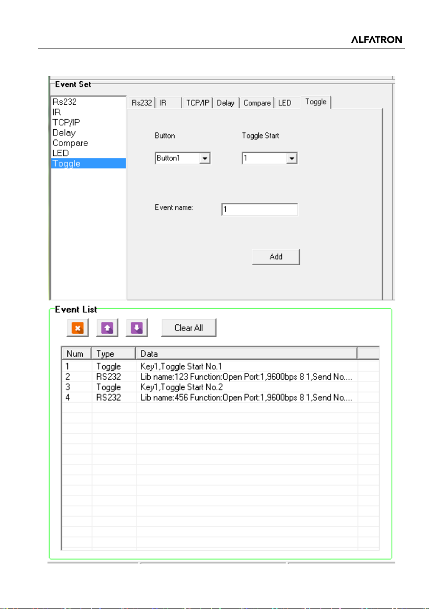
The button type can be set as “Toggle”, in this type, the button can be regarded as a
composite key. Below is an example to show you the use of this function:
Operation procedure:
1) Take Key 1 for example, click “1” and select the action type “Toggle”.
18
Page 24
ALF-IP6
2) Add toggle & RS232 events for the Button 1.
19
Page 25
ALF-IP6
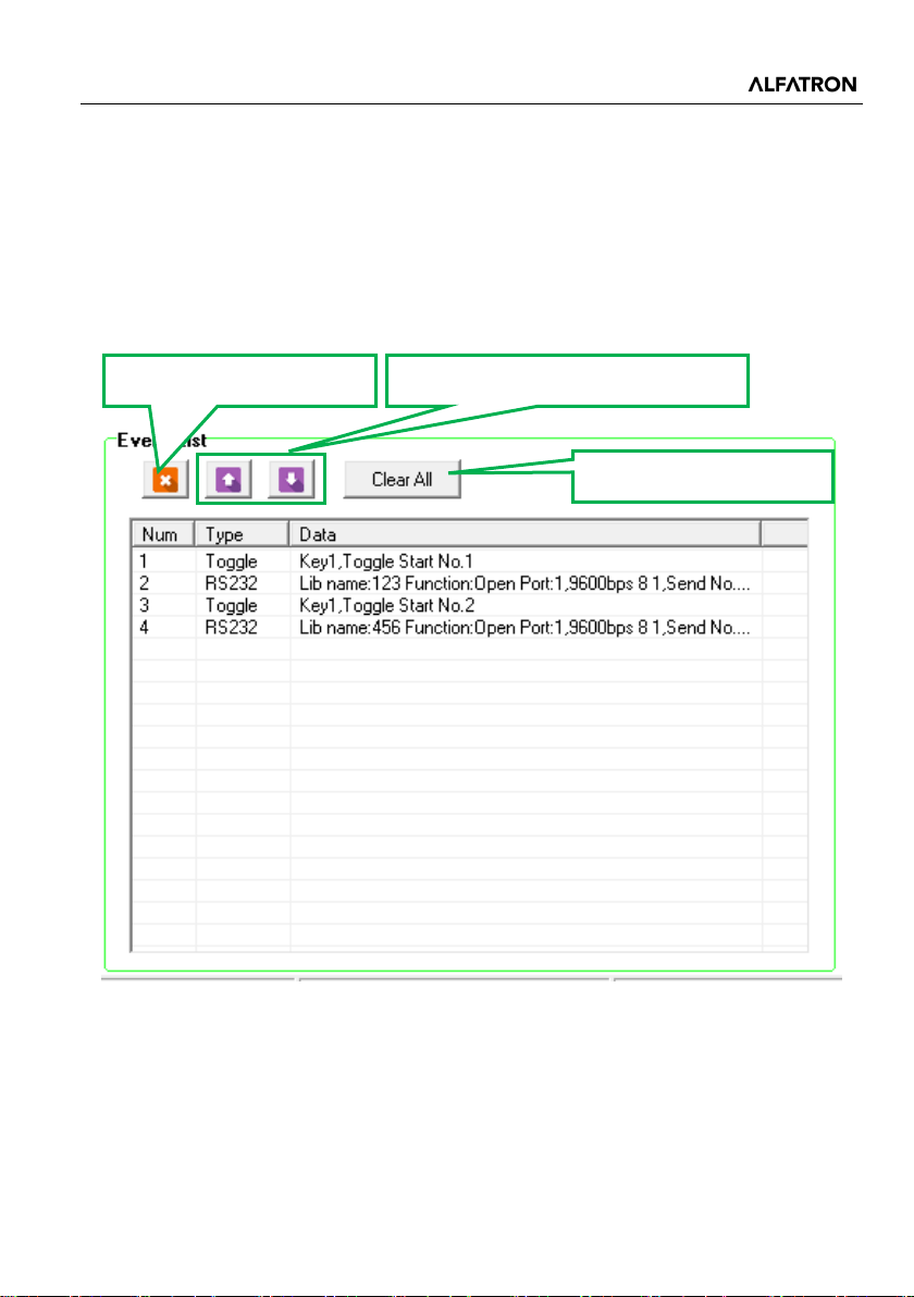
Delete the selected event.
Adjust the execution order for events.
Clear all events.
3) Press the Button 1, event Num 2 will be executed, press Button 1 again, and the
event of Num 4 will be executed.
4.5 Event List
The event list shows all events of the selected action. The executing priority abides by
the Num order, as displayed below. If there is an event executed incorrectly, all the
events that follow it will not be executed.
20
Page 26
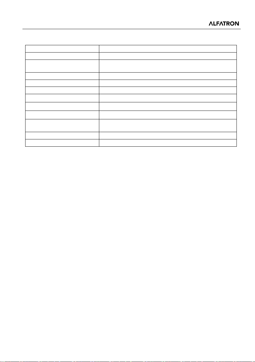
ALF-IP6
Program Port
TCP/IP
Output Port
3 x RS232, 2 x IR
3 x 3-Pin Pluggable terminal blocks,
2 x 2-Pin Pluggable terminal blocks,
Baud Rate and Protocol
9600 baud, 8 data bits, 1 stop bit, no parity
Software
ALF-IP6
Power Consumption
1W (Max)
Operation Temperature
0 ~ +40℃
Storage Temperature
-10 ~ +55℃
Relative Humidity
10% ~ 90%
Input: 100VAC~240VAC, 50/60 Hz;
Output: 12VDC
Net Weight
150g
Case Dimensions(W*H*D)
70mm x 114mm x 41mm
5. Specification
Output Connector
Power Supply
21
Page 27
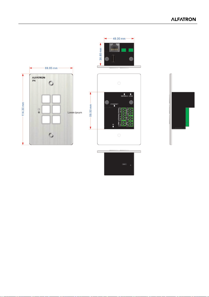
ALF-IP6
6. Panel Drawing
22
Page 28

ALF-IP6
7. Troubleshooting & Maintenance
1) Should the ALF-IP6 not power up, please check, and ensure the power cord is well
connected; the power connections cannot be mixed or incorrectly connected. Then
restart the device, should the error persist, the ALF-IP6 may be defective. Please
send it to the dealer for repair.
2) If connection is unsuccessful, please ensure the network segment of the control PC
and the ALF-IP6 is the same.
3) When the LED of a button does not light up, please check if there is a compare
event in this button. If yes, delete the ‘compare’ and try again. Should the error
persist, the LED may be damaged. Please send the unit to the dealer for repair.
4) When serial commands are sent without the functions being executed, please
check the baud rate, and make sure it is correct and that the serial connection is
well connected.
Remarks: For further assistance or solutions, please contact your local distributor.
23
Page 29

ALF-IP6
After-sales Service
Should you experience problems using the Alfatron ALF-IP6 please refer to the
Troubleshooting and Maintenance (7) section. Should the error persist, note that
any transport costs of the equipment to the distributor are borne by the user during
the warranty.
Product Limited Warranty: Alfatron warrants that its products will be free from
defects in materials and workmanship for seven years, which starts from the first
day of purchase.
Proof of purchase in the form of a bill of sale or receipted invoice which is evidence
that the unit is within the warranty period must be presented to obtain warranty
service.
What the warranty does not cover (servicing is available at a fee):
• Warranty expiration.
• Factory applied serial number has been altered or removed from the product.
• Damage, deterioration, or malfunction caused by:
• Normal wear and tear.
• Use of supplies or parts not meeting product specifications.
• No certificate or invoice as the proof of warranty.
• The product model showed on the warranty card does not match with the product
or if the product had been altered.
• Damage caused by force majeure.
• Servicing not authorized by Alfatron.
• Any other causes which do not relate to a product defect.
• Delivery, installation or labour charges for installation or setup of the product.
Technical Support: Contact our after-sales department at
www.alfatronelectronics.com
24
Page 30

ALF-IP6
Warranty
1.1 This limited warranty covers defects in materials and workmanship in this
product.
1.2 Should warranty service be required, proof of purchase must be presented to
the Company. The serial number on the product must be clearly visible and not
have been tampered with in any way whatsoever.
1.3 This limited warranty does not cover any damage, deterioration or malfunction
resulting from any alteration, modification, improper or unreasonable use or
maintenance, misuse, abuse, accident, neglect, exposure to excess moisture, fire,
improper packing, and shipping (such claims must be presented to the carrier),
lightning, power surges, or other acts of nature. This limited warranty does not
cover any damage, deterioration or malfunction resulting from the installation or
removal of this product from any installation, any unauthorized tampering with this
product, any repairs attempted by anyone unauthorized by the Company to make
such repairs, or any other cause which does not relate directly to a defect in
materials and/or workmanship of this product. This limited warranty does not cover
equipment enclosures, cables or accessories used in conjunction with this product.
This limited warranty does not cover the cost of normal maintenance. Failure of the
product due to insufficient or improper maintenance is not covered.
1.4 The Company does not warrant that the product covered hereby, including,
without limitation, the technology and/or integrated circuit(s) included in the product,
will not become obsolete or that such items are or will remain compatible with any
other product or technology with which the product may be used.
1.5 Only the original purchaser of this product is covered under this limited warranty.
This limited warranty is not transferable to subsequent purchasers or owners of this
product.
1.6 Unless otherwise specified, the goods are warranted in accordance with the
manufacturer’s product specific warranties against any defect attributable to faulty
workmanship or materials, fair wear and tear being excluded.
1.7 This limited warranty only covers the cost of faulty goods and does not include
the cost of labor and travel to return the goods to the Company’s premises.
1.8 In the event of any improper maintenance, repair or service being carried out by
any third persons during the warranty period without the Company’s written
authorization, the limited warranty shall be void.
1.9 A 7 (seven) year limited warranty is given on the aforesaid product were used
correctly according to the Company’s instructions, and only with the use of the
Company’s components.
1.10 The Company will, at its sole option, provide one of the following three
25
Page 31

ALF-IP6
remedies to whatever extent it shall deem necessary to satisfy a proper claim under
this limited warranty:
1.10.1 Elect to repair or facilitate the repair of any defective parts within a
reasonable period of time, free of any charge for the necessary parts and labor to
complete the repair and restore this product to its proper operating condition.; or
1.10.2 Replace this product with a direct replacement or with a similar product
deemed by the Company to perform substantially the same function as the original
product; or
1.10.3 Issue a refund of the original purchase price less depreciation to be
determined based on the age of the product at the time remedy is sought under this
limited warranty.
1.11 The Company is not obligated to provide the Customer with a substitute unit
during the limited warranty period or at any time thereafter.
1.12 If this product is returned to the Company this product must be insured during
shipment, with the insurance and shipping charges prepaid by the Customer. If this
product is returned uninsured, the Customer assumes all risks of loss or damage
during shipment. The Company will not be responsible for any costs related to the
removal or re-installation of this product from or into any installation. The Company
will not be responsible for any costs related to any setting up this product, any
adjustment of user controls or any programming required for a specific installation
of this product.
1.13 Please be aware that the Company’s products and components have not been
tested with competitor’s products and therefore the Company cannot warrant
products and/or components used in conjunction with competitor’s products.
1.14 The appropriateness of the goods for the purpose intended is only warranted
to the extent that the goods are used in accordance with the Company’s installation,
classification, and usage instructions.
1.15 Any claim by the Customer which is based on any defect in the quality or
condition of the goods or their failure to correspond with specification shall be
notified in writing to the Company within 7 days of delivery or (where the defect or
failure was not apparent on reasonable inspection by the Customer) within a
reasonable time after discovery of the defect or failure, but, in any event, within 6
months of delivery.
1.16 If delivery is not refused, and the Customer does not notify the Company
accordingly, the Customer may not reject the goods and the Company shall have no
liability and the Customer shall pay the price as if the goods had been delivered in
accordance with the Agreement.
1.17 THE MAXIMUM LIABILITY OF THE COMPANY UNDER THIS LIMITED
26
Page 32

ALF-IP6
WARRANTY SHALL NOT EXCEED THE ACTUAL PURCHASE PRICE PAID FOR
THE PRODUCT
27
 Loading...