

Page 1
www.alfatronelectronics.com
ALFATRON ELECTRONICS GmbH
Germany
ALF-DSP88-U
8x8 Digital Sound Processor
All Rights Reserved
Version: ALF-DSP88-U V1.1 22022022
Page 2

ALF-DSP88-U
Table of Contents
1. Hardware .......................................................................................... 5
1.1 Safety Instructions .................................................................................................................................... 5
1.2 Audio Wiring Reference ........................................................................................................................... 6
1.3 Specifications ........................................................................................................................................... 7
1.4 Mechanical ............................................................................................................................................... 8
1.5 Front Panel ............................................................................................................................................... 8
1.6 Rear Panel ................................................................................................................................................ 9
2. Technology Overview ....................................................................... 9
2.1 Introduction to DSP Technology .............................................................................................................. 9
2.2 Audio Input Section ................................................................................................................................ 10
2.3 Audio Output Section ........................................................................................................................... 111
2.4 Floating Point DSP ............................................................................................................................... 111
2.5 Audio Flow ............................................................................................................................................ 133
2.6 Typical System Application .................................................................................................................. 144
3. Software ........................................................................................ 155
3.1 Software Installation ............................................................................................................................. 155
3.2 Using the Software ................................................................................................................................. 16
3.3 Audio Module Parameters ...................................................................................................................... 16
3.3.1 Input Source .................................................................................................................................. 177
3.3.2 Expander ....................................................................................................................................... 177
3.3.3 Compressor & Limiter ...................................................................................................................... 19
3.3.4 Automatic Gain Control ................................................................................................................... 20
3.3.5 Equalizers ........................................................................................................................................ 21
3.3.6 Feedback Suppressor ..................................................................................................................... 22
3.3.7 AutoMixer ......................................................................................................................................... 24
3.3.8 Acoustic Echo Cancelation .............................................................................................................. 25
3.3.9 Noise Suppression .......................................................................................................................... 26
3.3.10 Matrix ............................................................................................................................................. 26
3.3.11 High & Low Pass Filter .................................................................................................................. 27
3.3.12 Delay .............................................................................................................................................. 28
3.3.13 Output ............................................................................................................................................ 28
-2-
Page 3

ALF-DSP88-U
3.3.14 USB Interface ................................................................................................................................ 28
3.4 Setting Menu .......................................................................................................................................... 30
3.4.1 File Menu ......................................................................................................................................... 30
3.4.2 Device Setting ................................................................................................................................. 31
3.4.3 GPIO Setting.................................................................................................................................... 31
3.4.4 Group Setting .................................................................................................................................. 34
3.4.5 Panel Setting ................................................................................................................................... 35
3.4.6 Help Menu ....................................................................................................................................... 37
4. Control ............................................................................................ 38
4.1 External Control Programmer ................................................................................................................ 38
4.2 Control Protocol ...................................................................................................................................... 38
4.3 Serial Port-to-UDP (RS232 To UDP) ..................................................................................................... 40
5. FAQs ............................................................................................... 41
Appendix A: Module ID Distribution .................................................... 42
Appendix B: Module Parameter Types (1) .......................................... 43
6. After-Sales ...................................................................................... 45
7. Warranty .......................................................................................... 46
-3-
Page 4
ALF-DSP88-U
Preface
Read this user manual carefully before using the product. Pictures shown in this manual are for reference
only. Different models and specifications are subject to the real product.
This manual is only for operational instruction, please contact the local distributor for maintenance
assistance. The functions described in this version are updated as of September 2021. In the constant effort
to improve the product, we reserve the right to make functions or parameters changes without notice or
obligation. Please refer to the dealers for the latest details.
FCC Statement
This equipment generates, uses, and can radiate radio frequency energy and, if not installed and used in
accordance with the instructions, may cause harmful interference to radio communications. It has been
tested and found to comply with the limits for a Class B digital device, pursuant to part 15 of the FCC Rules.
These limits are designed to provide reasonable protection against harmful interference in a commercial
installation.
Operation of this equipment in a residential area is likely to cause interference, in which case the user at
their own expense will be required to take whatever measures may be necessary to correct the interference.
Any changes or modifications not expressly approved by the manufacturer would void the user’s authority to
operate the equipment.
Do not dispose of this product with the normal household waste at the end of its life cycle. Return it to a
collection point for the recycling of electrical and electronic devices. This is indicated by the symbol on the
product, user manual or packaging. The materials are reusable according to their markings. By reusing,
recycling or other forms of utilisation of old devices you make an important contribution to the protection of
our environment. Please contact your local authorities for details about collection points.
-4-
Page 5
ALF-DSP88-U
1. Hardware
1.1 Safety Instructions
Safety Instructions
Important safety instructions:
1. Read these instructions.
2. Keep these instructions secure.
3. Pay attention to all warnings.
4. Follow all instructions.
5. Please keep the device away from water. The device cannot be exposed to water drips or water splashes; make
sure that there is no object with liquid near the device, such as a vase.
6. Please use dry cloth to clean the device.
7. Please do not block the vent. Please install the device based on the manufacturer's instructions.
8. Please do not install near any heat source, such as radiator, furnace, or other devices (including amplifiers) that
generate heat.
9. Please make use of a protective grounding connection to connect the device to the power socket. Please do not
use polarized plug or grounding plug. A polarized plug has two leaves, and one is wider than another. A grounding
plug has two leaves and a third ground terminal. The wide leaf or third ground terminal can provide safety for the
users. If the plug provided does not correspond with the power socket, please contact an electrician to replace the
old socket with a new one.
10. Protect the power cord so that it will not be trampled or jutted, particularly the plug, the socket and the
connections of cord and device.
11. Please use the accessories designated by the manufacturer.
12. Please only use a cart, a tripod, or a desk designated by the manufacturer, or sold together with the device. When
using a cart, please take care with the mobile cart / device to avoid injury from rollover.
13. Please unplug the device during a thunderstorm or during the idle period.
14. Please contact our qualified maintenance personnel to deal with all maintenance related issues. For example, the
power cord gets damaged, liquid has spilt over, or an object falls onto the device; the device is exposed to rainwater
or moisture; the operations are not correct, or the device completely fails.
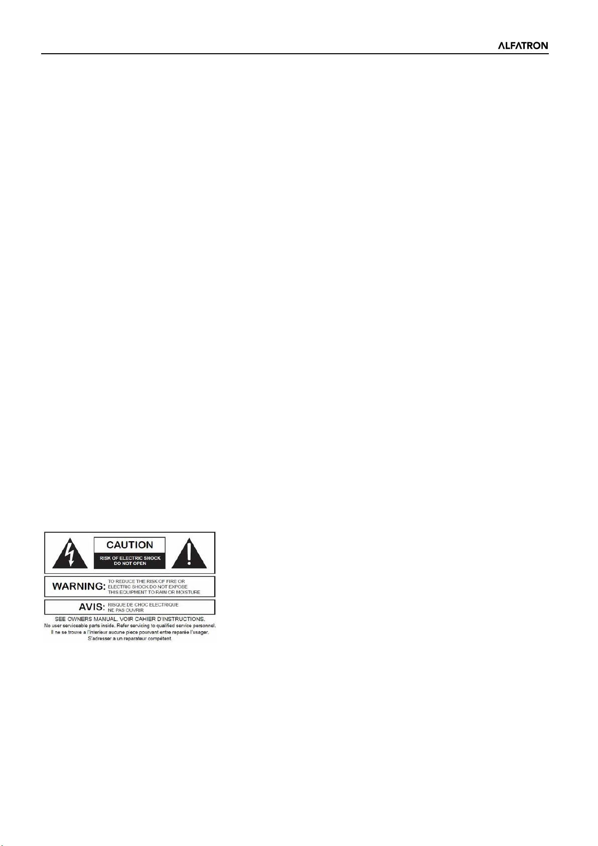
The lightning logo (an equilateral triangle with an arrow) is used to make the users aware of the uninsulated
"dangerous voltage" within the product shell, which may cause electric shock. An equilateral triangle with an
exclamation mark is adopted to make the users understand the importance of the operations and maintenance
instructions given in the appendixes attached to the product.
Warning: In order to prevent electric shock, please do not use a polarized plug provided by a device with an
extension cord. The socket outlet cannot be inserted except for the sharp end.
-5-
Page 6
ALF-DSP88-U
1.2 Audio Wiring Reference
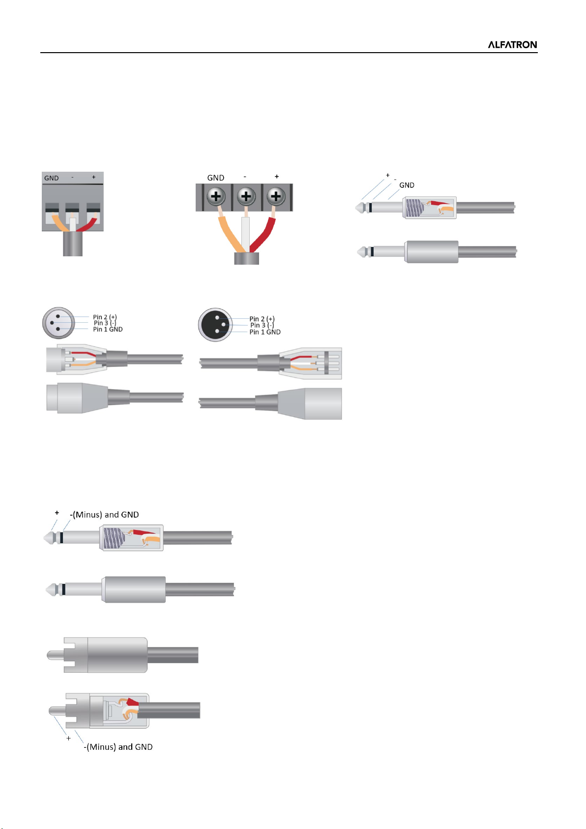
Balanced Audio Connection
Any of these audio connections may occur on either input or output terminals.
Unbalanced Audio Connection
RCA audio connections and 1/4-inch TS audio connections are unbalanced connections. A multi-strand shielded
conductor may be installed on both ends of the unbalanced connection. In such a case, please note to join the
negative and shield conductors as indicated.
-6-
Page 7
ALF-DSP88-U
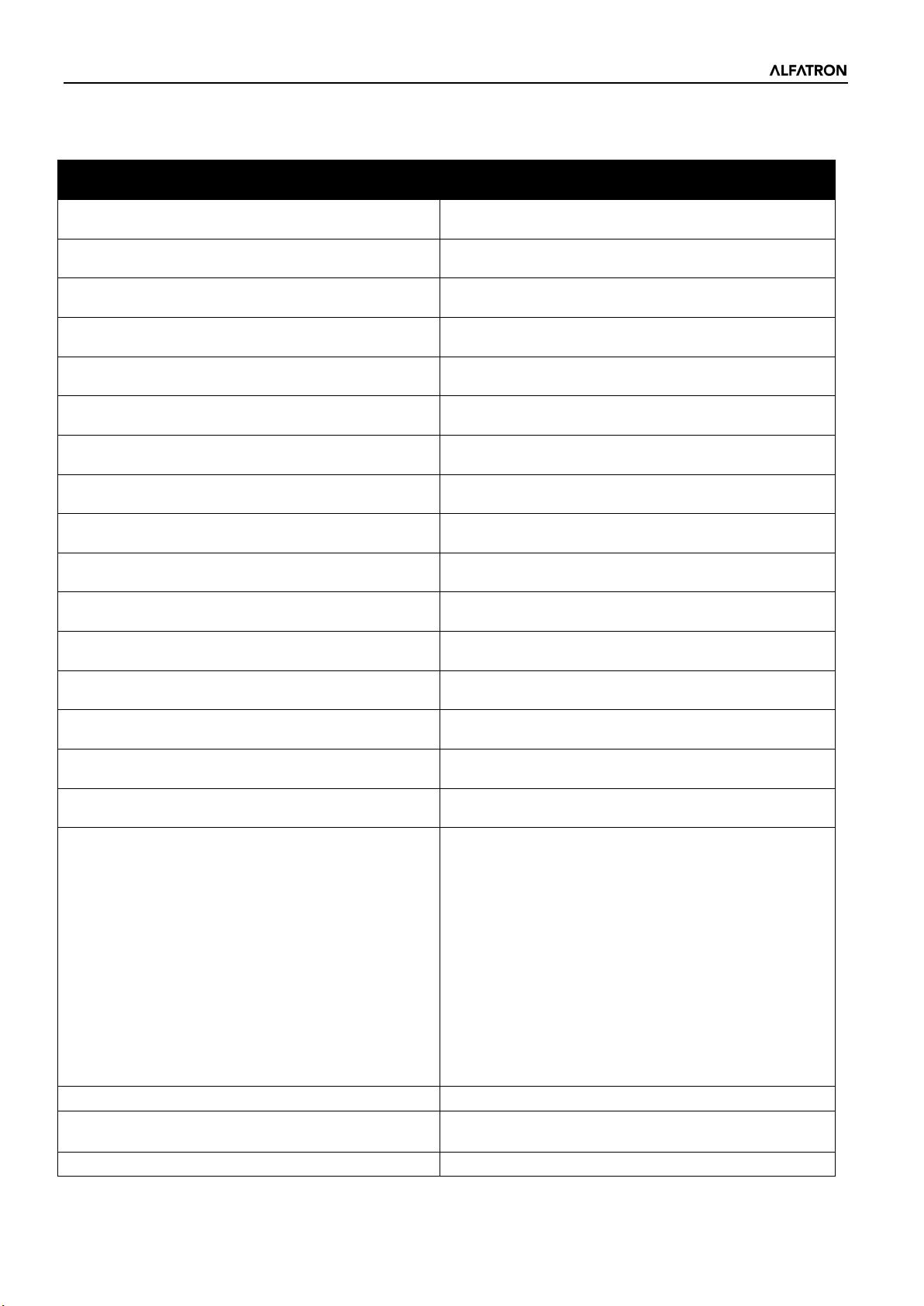
Audio Processing Functions
Acoustic Echo Cancellations (AEC)
Delay
USB AUDIO
1 In – 1 Out
Control Options
IP based PC software and host control.
GPIO
1.3 Specifications
Alfatron ALF-DSP88-U
SPECIFICATIONS
Processor ADI SHARC 21489(x2)
Sampling rate/Digitalizing bit 48K/24bit
Input Gain 0 – 48dB in 3dB Steps
Phantom Power 48V
Frequency Response (20~20KHz) ±0.2dB
Maximum Level +24dBu
THD + Noise 0.003%@4dBu
Dynamic Range 110 dB
Background Noise (A-weighted) -91 dBA
Common Mode Rejection Ratio @60Hz 80dB
Channel Isolation @1KHz 108 dB
Input Impedance (Balanced Connection) 9.4KΩ
Output Impedance (Balanced Connection)
System Delay <3ms
Inputs
Outputs
102Ω
8 Balance Line/Mic Inputs on Phoenix Connections
8 Balance Line Outputs on Phoenix Connections
Automatic Gain Control (AGC)
Noise Suppression
Auto Mixer
Matrix
8 Band Parametric EQ (Inputs & Outputs)
High / Low Shelf Filters
Expander
Compressor / Limiter
Feedback Suppressor
Third party control for RS-485 and RS-232.
8 Channel Logic Output
-7-
Page 8
ALF-DSP88-U
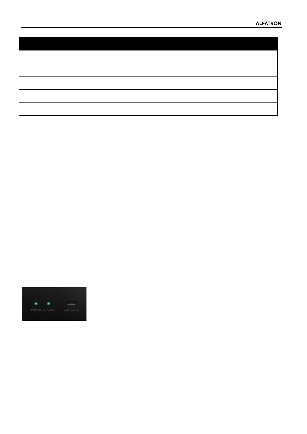
MECHANICAL
Working Power AC110~240V 5Hz-60Hz
Maximum Power Consumption <40W
Rack Space Required 1U
Dimensions (Width x Depth x Height) 482 x 260 x 45mm
Shipping Weight 3KG
1.4 Mechanical
Space required:
1U (width * depth * height: 18.91″ x 9.5″x 1.72″ / 48.02 cm x 24.13 cm x 4.37 cm). The reserved head space is not
included in the depth.
An additional space at least 3 inches must be reserved for the connection of rear panel. The reserved depth depends
on the wire used and the connection mode.
Electrical Properties:
Maximum universal input power: 110-240 VAC, 50/60 Hz, 40 W.
Ventilation:
The recommended highest operating ambient temperature is 30℃ / 86℉.
Make sure that there is no obstruction on both sides (a gap of at least 5.08cm / 2 inches shall be reserved). Please do
not cover the thermal vents of the device with newspapers, a tablecloth, or any other objects.
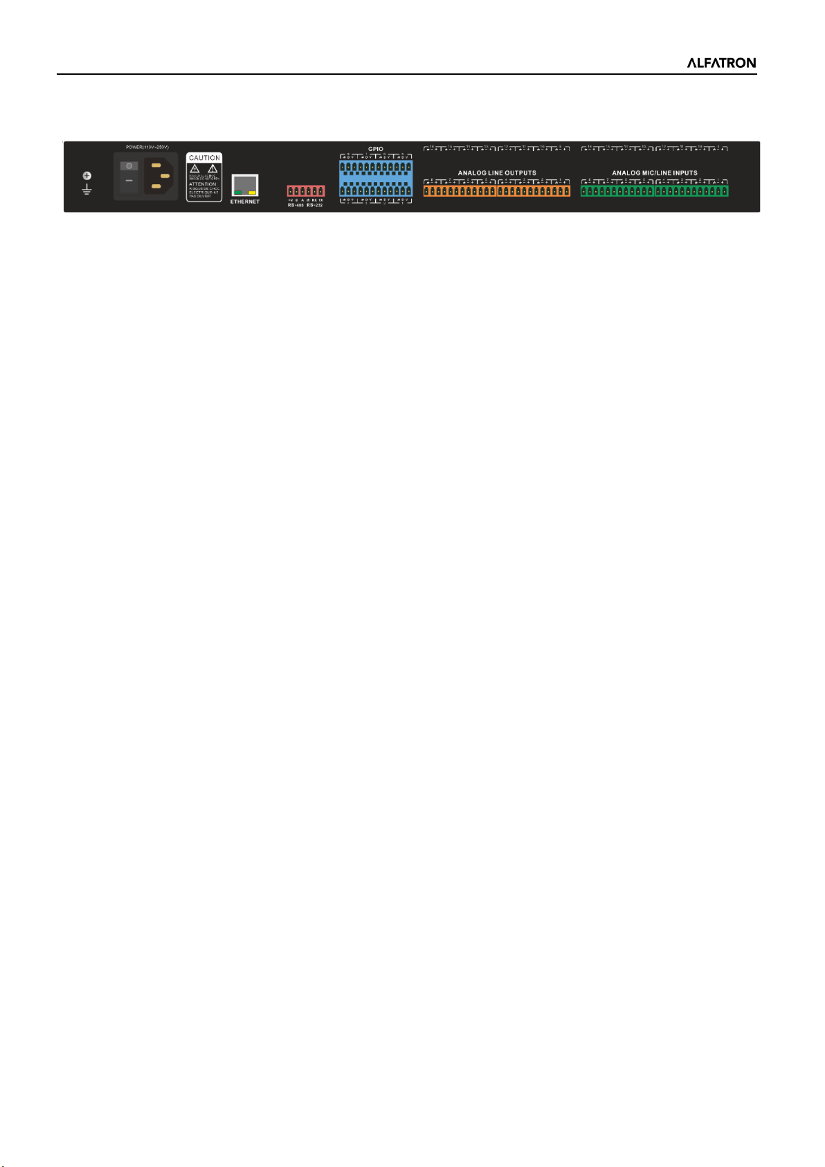
1.5 Front Panel
Power: LED power indicator.
STATUS: The operational status indicator of the device.
USB AUDIO: USB soundcard (1-in-1-out), for connection to host PC.
-8-
Page 9
ALF-DSP88-U
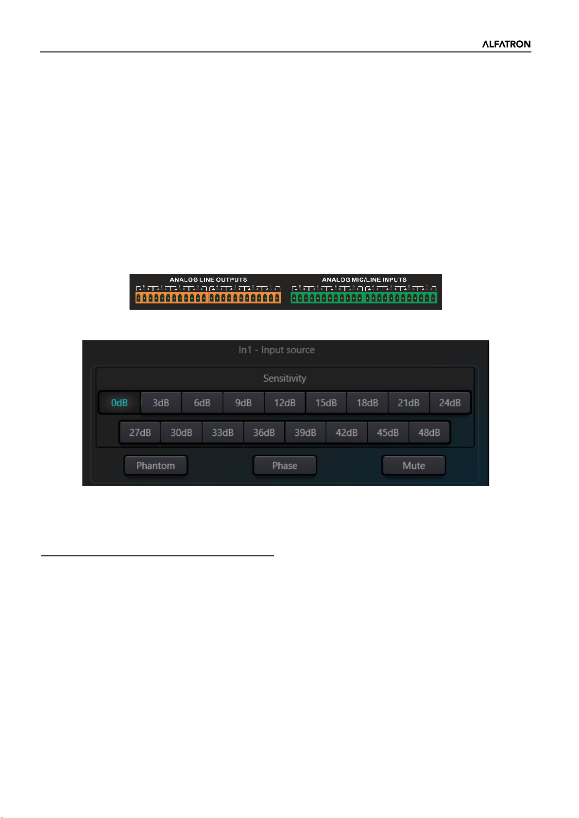
1.6 Rear Panel
Power Source:
Power switch
Fuse
Power connector: (Supports 110 - 240V AC 50/60Hz, and supports a maximum power of 40W)
Ethernet Connector
10/100 Base-T Ethernet connector is used for IP-based PC software and host control, and third-party accessory
controller.
RS485
Used for the serial communication port Tx = sending or data output or Rx = receiving or data input that connects
to a third-party control device.
RS485 can be used for voice tracking control (or other output commands), or for bus input control. A central
command can be used to conveniently integrate it into your software.
Port setting: 115200 baud (default), 8 data bits, 1 stop bit, no parity, no flow control.
RS232
Used for serial communication; port Tx = sending or data output or Rx = receiving or data input that connects to
a third-party control device.
Port setting: 115200 baud (default), 8 data bits, 1 stop bit, no parity, no flow control.
GPIO
12-bit 3.81 mm terminal
8-channel logic output, with 4 pairs of universal grounding pins. After being activated, the logic output will be
low (0V), and the internal voltage will be high (5V) when not activated. You may directly power and light up
external LEDs. The logic output can be driven by the logic output control module in the device design. Polarity
and threshold can be set in the software.
2. Technology Overview
2.1 Introduction to DSP Technology
Audio Digital Signal Processors (DSP) are equipped with several core technical features to simulate the work of
an audio engineer. DSP-based audio management, routing, processing, and control is facilitated via a computer
running the GUI Software for the Audio DSP Hardware. This Manual mainly introduces the techniques used to
achieve this goal.
The Alfatron DSP Controller software is a Windows-based application, which is used to configure and control the
DSP hardware. The Alfatron DSP Controller has 16 built-in presets, and the modules and sequences for each
preset can be flexibly designed in accordance with the designer's requirements. Once the design is completed,
it can be saved for future use. The sequences and parameters of the DSP Controller's built-in processing
modules work with most application scenarios without needing any changes.
-9-
Page 10
ALF-DSP88-U
The Alfatron DSP Controller is a full-feature application, including parameter adjustments and peripheral
accessory settings of all modules, such as RS232, RS485, and click-and-drag panel configuration etc. The most
interesting part is the user interface, which allows the engineer to customize the user interface so that the
integrator can edit it, or the onsite technicians or end users who have no idea of the relevant techniques can
operate it. Advanced security features make it possible for the end user to only access the controls allowed by
the engineer, or designer.
2.2 Audio Input Section
The Alfatron ALF-DSP88-U supports up to 8 fixed analogue audio inputs, which can be connected via removable
balanced phoenix connectors. The analogue input section supports microphone or line-level signals whose
nominal levels range from 0dBu to +48dBu in 3dBu steps.
+48VDC phantom power can be independently switched on/ off for each input.
Preamp gain and phantom power can be conveniently controlled via the DSP Controller.
The Analogue to Digital (A/D) converter, or ADC, adopts an advanced 24-bit 256X sampling converter.
Analogue to Digital (A/D) Converter Technical Specs:
Sampling rate: 48kHz
THD+N: 105dB
Dynamic range: 120dB
Audio format: 24Bit MSB TDM
-10-
Page 11

ALF-DSP88-U
2.3 Audio Output Section
The Analogue output section refers to the digital to analogue (D/A) converter, or DAC, also adopts an advanced
24-bit 256X sampling converter. Just like the A/D converter, it also uses multi-bit architecture for broader
dynamic range. Unit gain (0dB) is set via volume control, and the analogue output section is corrected as +4dBu
with 20dB headroom. That is to say that 0dBFS digital signal is equivalent to +24dBu output signal. If other signal
levels are required, you may change the output volume to achieve it.
Digital to Analogue (D/A) Technical Specs:
Sampling rate: 48kHz
THD+N: -100dB
Dynamic range (A-weighted): 118dB
Audio format: 24Bit MSB TDM
On the software output interface there are two controls: Phase and Mute.
Phase: The phase button inverts the phase of the output signal by swopping the polarity.
Mute: Mutes the analogue output of the respective channel
2.4 Floating Point DSP
The ALF-DSP88-U adopts analogue devices’ ADI SHARC audio processors, enabling 32-bit and 40-bit floatingpoint processing, which can be compared to 40-bit floating-point processing of other devices. Floating-point
processing provides prominent advantages for the users in terms of sound quality and usability.
Fixed-Point Processing Limitations
Fixed-point processing has its own disadvantages. If there is a significant change in gain, data loss or a more
severe error may occur, including clipping or distortion. For example, the processing of 24-bit fixed point-based
audio signal, in some cases, if you attenuate the signal to 42dB, the new signal only includes 17-bit information.
Due to gain attenuation, 7 bits of information will be lost forever. Worse than that is the clipping distortion. For
a signal nearly close to 0dBFS, the signal will be clipped at 0dBFS, and audio distortion will occur. Even if the
signal level is adjusted to below 0dBFS through post-regulation, the clipping has occurred, and the distortion still
exists. Fixed point processing can create some headroom above 0dBFS, but by doing so, some bits have to be
abandoned. For example, if a 12dB (2 bits) headroom is created, a 24-bit system will only have 22 bits.
-11-
Page 12

ALF-DSP88-U
Floating-Point Processing
On the contrary, by taking advantage of floating-point processing, no matter what the signal level is, all available
bits are uniformly distributed to the signals. Basically, the floating points use some bits as indexes to set up
general signal level and distribute the remaining bits to signals with independently stored level. As a result, no
matter what kind of level (from -200dB and 200dB below to 0dBFS above, the stored signal's accuracy is
optimized without clipping distortion. SHARC provides 32-bit and 40-bit accurate processing; through 32-bit
processing, 25 bits are distributed to storage signals no matter what its signal level is. This means that, based on
at least 1-bit low level signal, its accuracy is always significantly superior to 24-bit fixed point processing.
Through expanded 40-bit accurate processing, 33-bit storage signals can be achieved.
Practical Significance
What's the practical significance of floating-point processing for the users? The gain stages between multiple
modules can be ignored. If the signal level of a module is reduced by 50dB and is then restored to its original
value through another processing, data loss will not occur. In the fixed-point system, the users must check other
signal levels before sending it to the A/D converter because all digital-to-analogue converters adopt fixed points.
In the DSP system, if you notice that your signal has been clipped before it is outputted and transmitted to the
digital-to-analogue converter, you may close it off immediately at the output section to correct the situation. If
using the fixed-point system, you would have to search each processing module to find the clipping source.
-12-
Page 13
ALF-DSP88-U
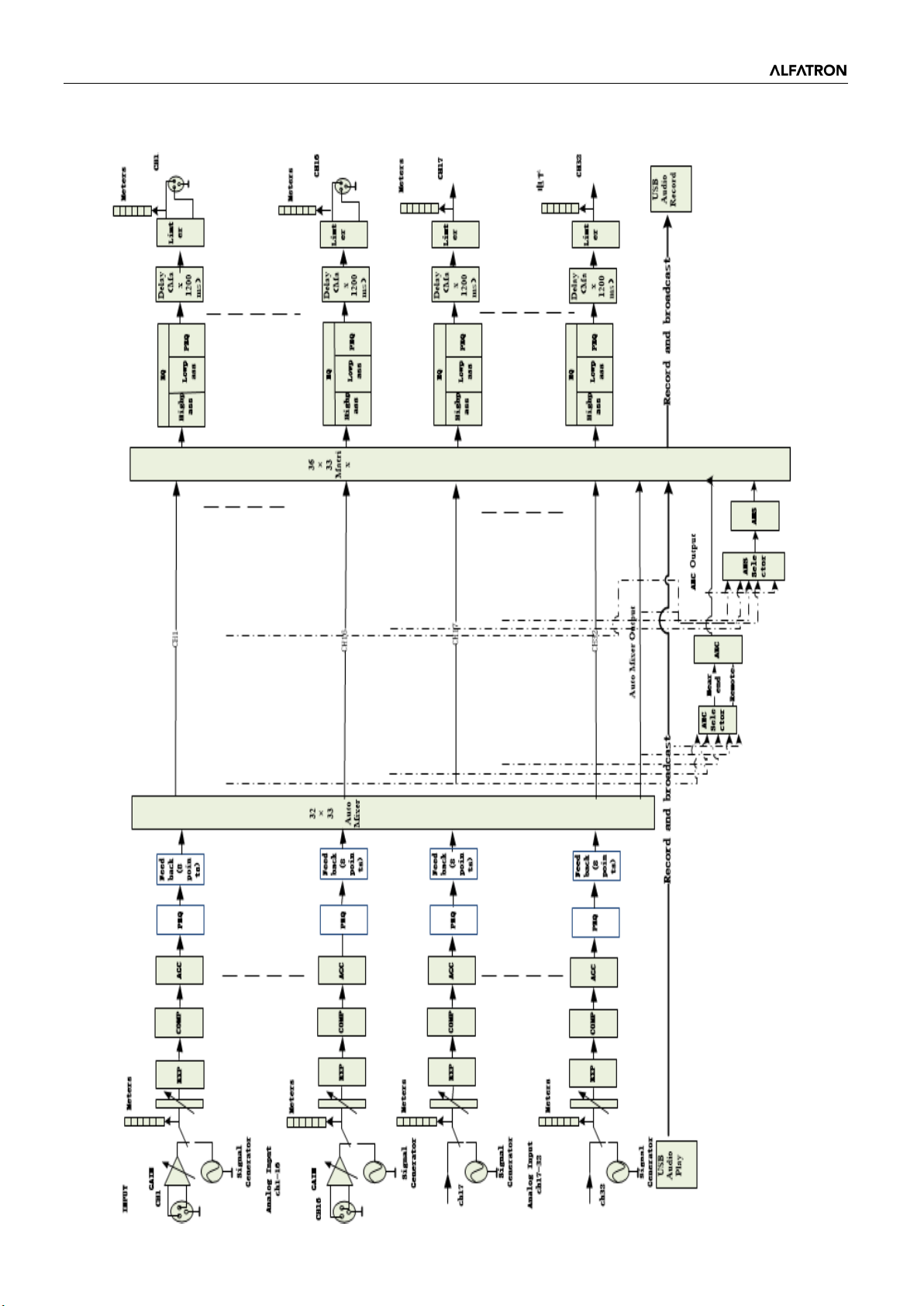
2.5 Audio Flow
-13-
Page 14
ALF-DSP88-U
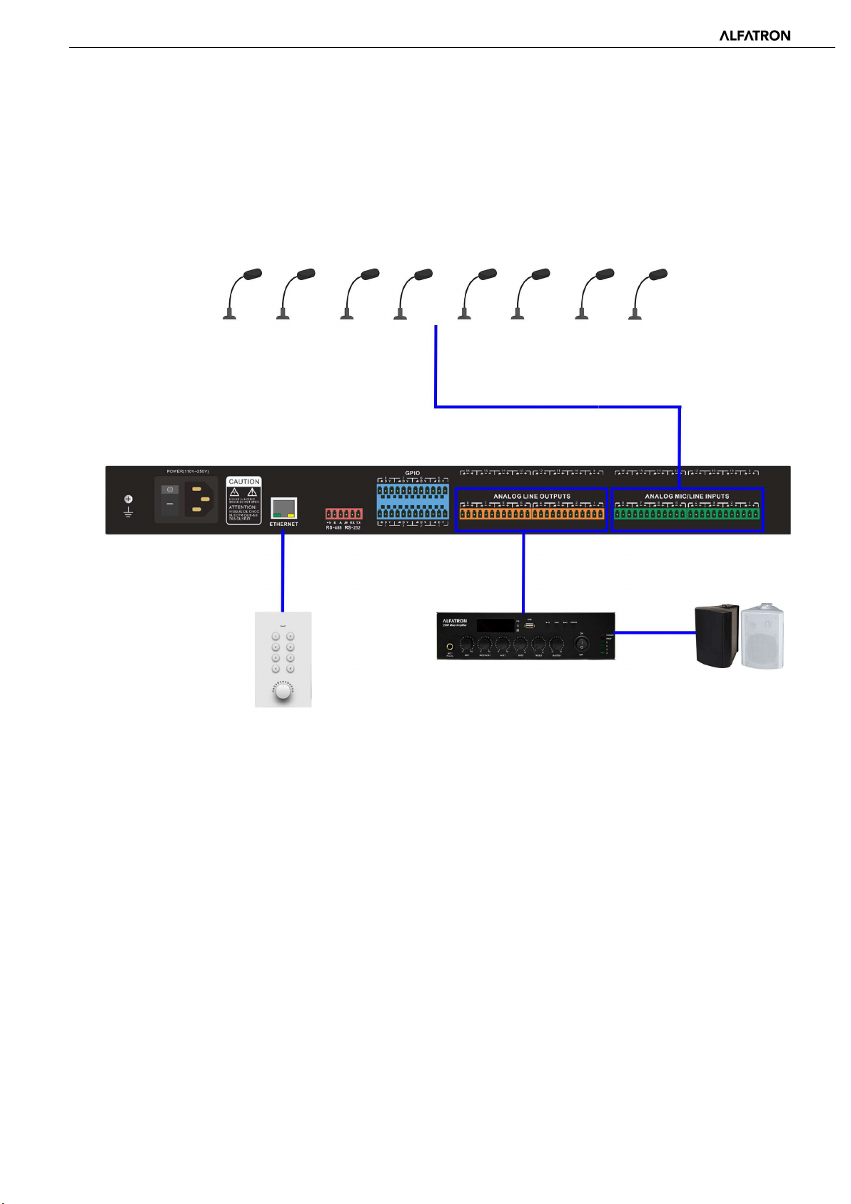
2.6 Typical System Application
Conferencing System: The processor can be connected to microphones, amplifiers, speakers, and other audio peripherals
(like USB audio from a PC) so as to process all audio signals and advanced algorithms like AEC in a typical conferencing
system. Additional audio matrixing, auto mixing and signal routing is also achieved in this application to facilitate excellent
audio quality in a conference.
-14-
Page 15

ALF-DSP88-U
3. Software
3.1 Software Installation
A Windows PC with:
• Intel i5 processor or higher
• 8 GB or higher memory
• 1 GB free storage space
• Windows 7 or higher version
• Minimum 1920 x 1080 resolution
• 24 bit or higher color
• Network (Ethernet) port
Software Installation:
Visit the device web page address: 169.254.10.227
1. Download software from the Alfatron website and install files.
2. Double click the downloaded file and install by following the instructions on the screen.
After the software is installed, read other parts of the help file, or execute the software.
After the software is installed, use one of the following methods to open the software:
1. Double Click Desktop Icon
2. Open from Start menu
-15-
Page 16
ALF-DSP88-U
3.2 Using the Software
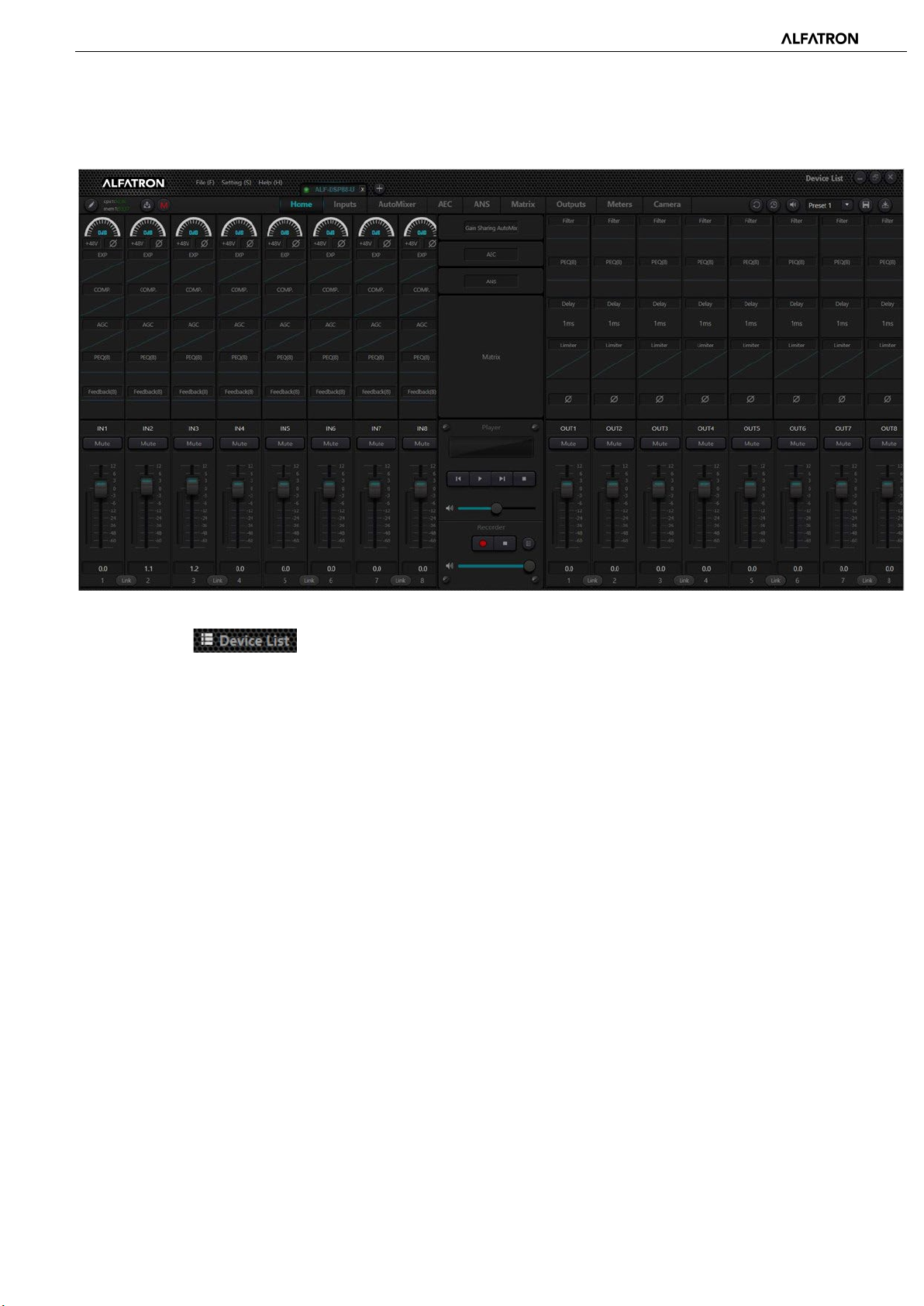
After enabling the software, the main menu is shown as below:
Click the button in the right corner of the main menu to find all processors on the network automatically.
The user may connect to the designated processor based on their own needs; after the connection, the indicator will flash;
each processor supports simultaneous connection and control for up to four users.
3.3 Audio Module Parameters
There are two ways to access the audio module parameters: first, click the input or output channel module you wish to
access, and enter the parameter interface of the module; secondly, right click the channel module and the configuration
interface will pop out. This is used for the following module parameters.
-16-
Page 17
ALF-DSP88-U
3.3.1 Input Source
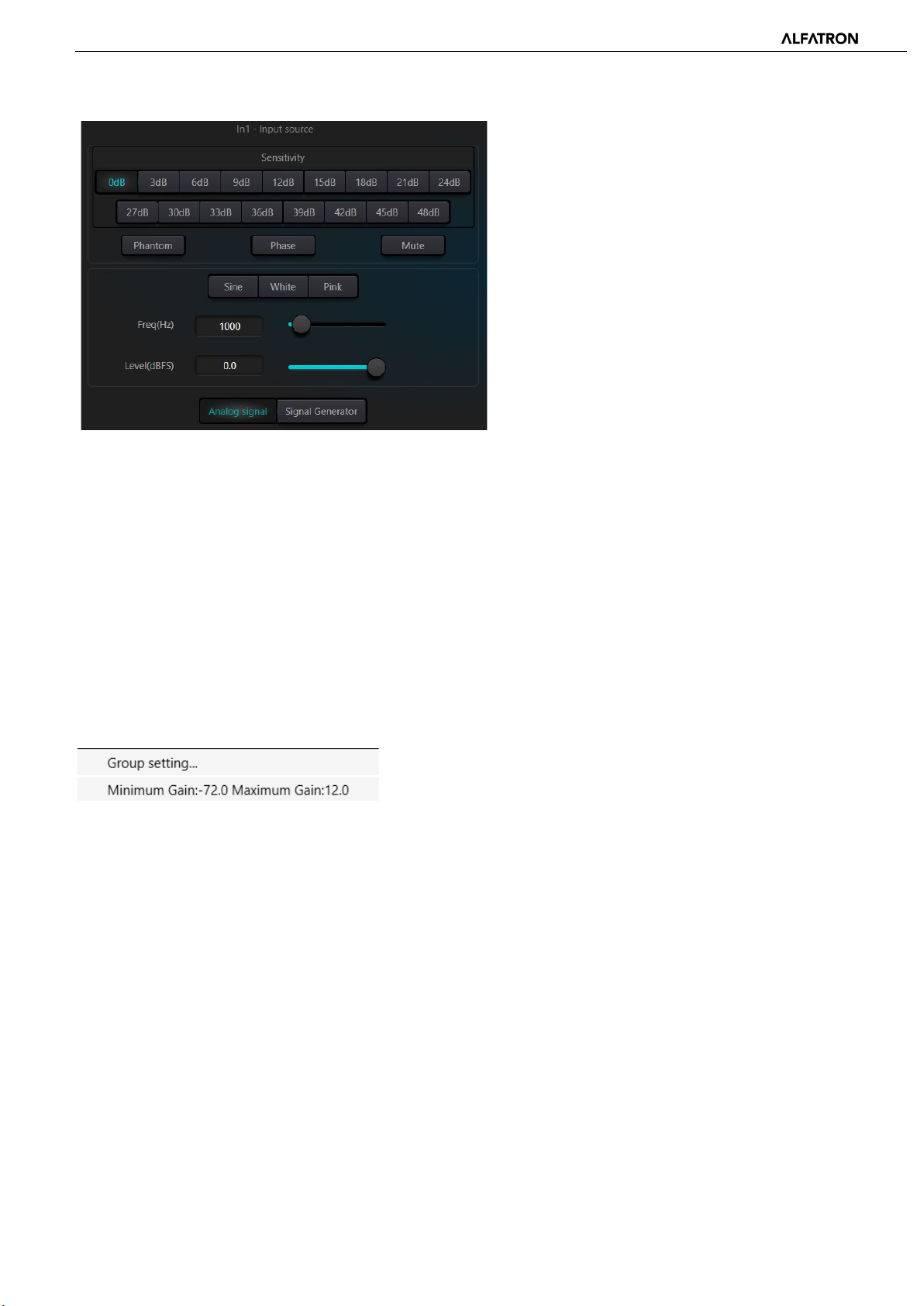
Sensitivity: Microphone gain, 0dB - 48dB in 3dB Steps.
Phantom Power: Provides +48V phantom power for external condenser microphones. (Do not enable phantom power when
the power is not required, this is to prevent damaging any non-Phantom powered devices when connected.)
Sine Wave: Select the Sine Wave button and drag the frequency to generate sine wave with selected frequency (selectable
20Hz - 20 kHz). You may regulate the output level (unit: dBFS) based on your requirements. Use the level fader to adjust or
click the text field to designate a value.
White Noise: When observed on the frequency spectrograph with constant bandwidth, and set to a flat frequency spectrum,
white noise signal has equal energy across all frequencies.
Pink Noise: The frequency intensity level of pink noise is mainly distributed in the middle and low frequency bands. It
decreases with a speed of 3dB/Oct in the middle and low frequency bands.
In addition, you may also find the following menu by right clicking each fader on the main menu.
Group Setting: Open the group setting interface window.
Minimum and Maximum Gains: Limit the maximum and minimum values of a channel. After it is commissioned, if you do
not wish that the system's stability is affected due to external factors, you may set up a maximum gain.
3.3.2 Expander
Although similar in concept, the expander has a different operating principle from the compressor. It can expand the
dynamic range of a signal. The most fundamental difference in these two devices lies in that, the compressor works on the
signal higher than the threshold, while the expander works on the signal lower than the threshold. Louder and softer signals
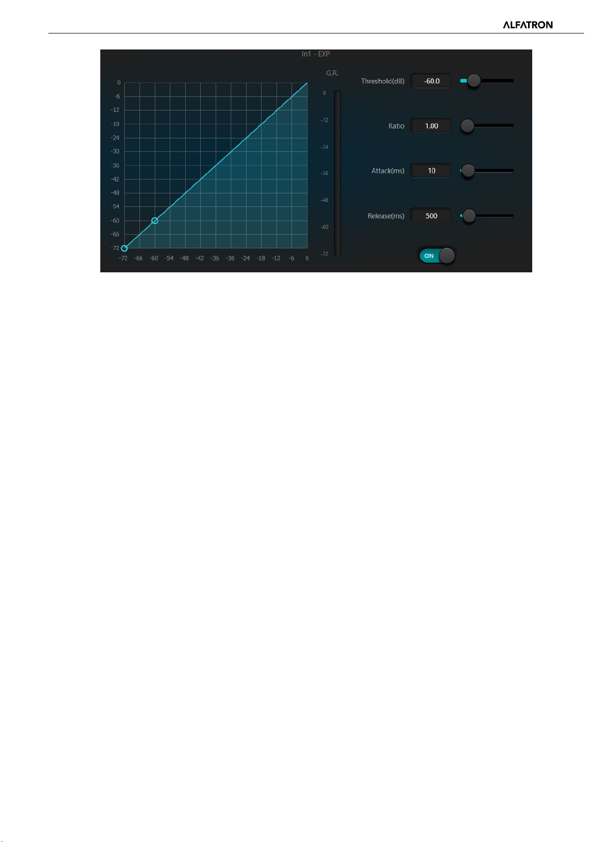
become relatively louder and softer respectively. It can be seen from Fig.3.2 that, when the expansion ratio reaches 1:2, the
input signal 20dB lower than the threshold will generate an output signal 40dB lower than the threshold. Thus, as shown
below, the signal lower than the threshold will extend downwards and cause softer level. When an expansion ratio 1:20 is
adopted. The expander seems to be a noise gate in terms of the transmission features. In fact, a noise gate is an expander
with a great expansion ratio.
-17-
Page 18
ALF-DSP88-U
The expander has the following control parameters:
Fig.3.2 Expander
Threshold: The expander activates only when the signal exceeds this threshold (allowing the transmission of the signal). As a
standard practice, the signal is often set at the ambient noise level
Ratio: Ratio refers to the slope below the threshold point on the gain curve. When the slope is set at a high level, gating will
activate.
Attack: Attack refers to the time that the expander will wait before activating when the input signal exceeds the threshold.
Shorter attack time allows to start the expander more quickly.
Release time: Release time refers to the delay in time required for the gain to be restored to normal when the input signal
drops lower than the threshold.
No matter the starting time or the release time, it just helps to reduce the speed of gain attenuation. That is to say, the
speed of the gain from -40dB to 0dB is slowed down due to the influence of Attack. The Attack time and Release time is
unrelated to the threshold. If the signal level falls below the threshold, the Attack time and Release time will have their own
respective influence on gain attenuation; when the signal level rises above the threshold, the gain attenuation produced by
the expander will disappear in accordance with the speed controlled by the Release time. When the gain attenuation is
reduced to 0dB, the expander will stop expansion. Later, when the signal reduces to below the threshold, the expander will
start again, and the release time will begin to work.
-18-
Page 19
ALF-DSP88-U
3.3.3 Compressor & Limiter
Compressor
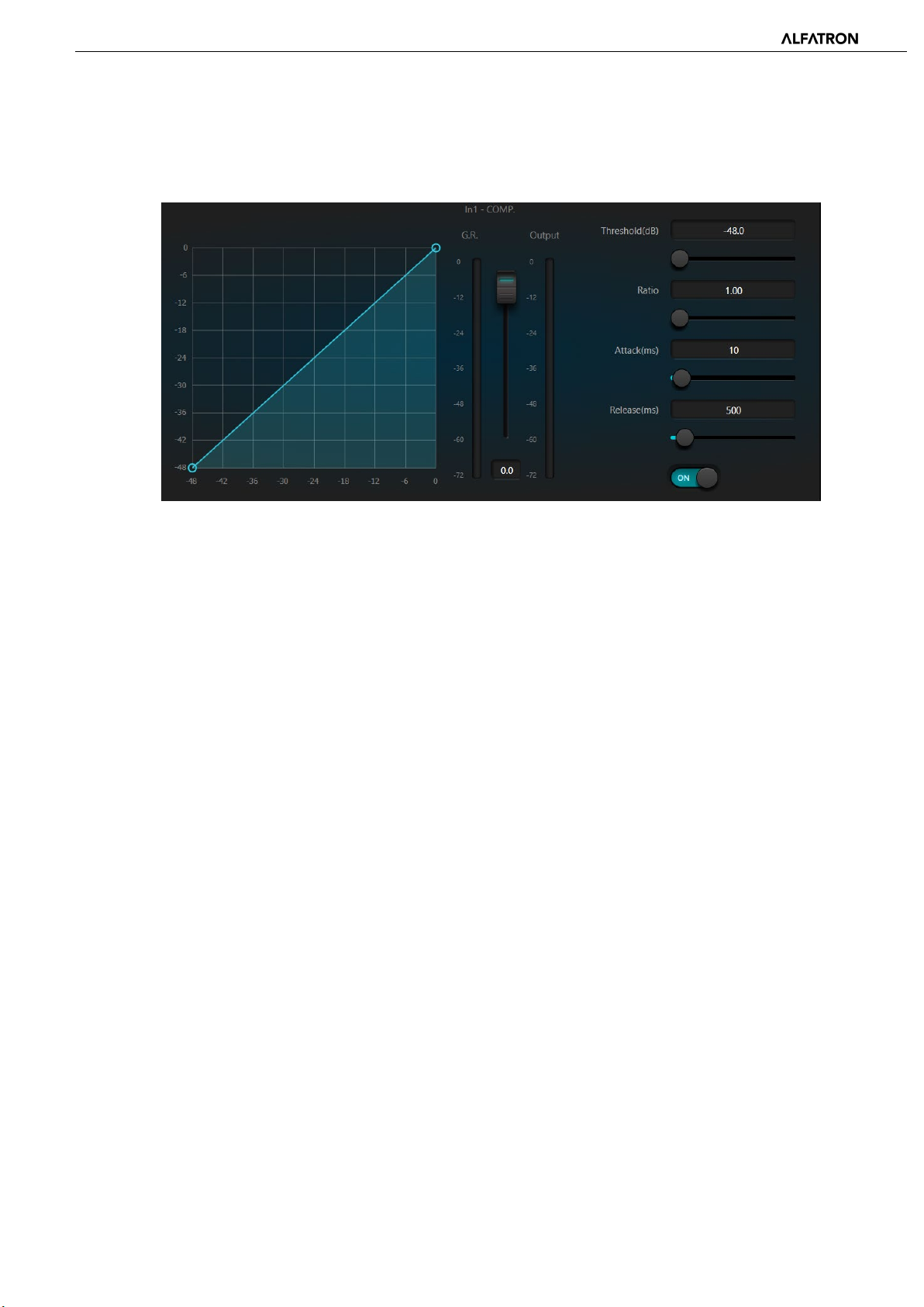
The compressor is used to reduce the dynamic range of the signal higher than the threshold set by the user, and to maintain
the dynamic range of the signal lower than the threshold. The compressor has the following control parameters:
Threshold: When the signal level is higher than the threshold, the compressor / limiter begins to reduce the gain. Any signal
that exceeds the threshold is regarded as overshoot signal, and its level will be reduced based on the ratio set. The more the
signal level exceeds the threshold, the more level is attenuated.
Ratio: It refers to the compression ratio. The ratio sets the attenuation degree of the overshoot signal to the threshold level.
The smaller the compression ratio is, the less compression will take place and signal will remain higher than the threshold.
Once the signal exceeds the threshold, the compression ratio decides the ratio of input signal variation to output signal
variation. For example, when the compression ratio is 1:2, if the input signal is 2dB higher than the threshold, the exceeding
part only changes by 1dB. A compression ratio of 1:1 suggests that the compressor does not attenuate the signal in
proportion. The adjustable range of compression ratio is 1-20.
Attack Time & Release Time: In order to maintain natural oscillation, it is generally accepted that part of the original level
will pass through the compression without any influence, or just minor influence. Likewise, if there is rapid sharp attenuation
and rapid recovery in the signal gain, the suction effect will occur. The attack and release time of the compressor is to avoid
this effect. The attack time sets the speed of gain attenuation, while the release time sets the speed of gain recovery.
Output Gain: Also called gain compensation. If the compressor significantly reduces the level of the signal, it may need to
enhance the output gain to maintain the volume. Output gain applies to all parts of the signal and is unrelated to other
parameter settings of the compressor.
Gain Reduction (G.R.) and output Level Meter: G.R. indicates the compressor's compression amount; output refers to the
output level of the signal that has passed through the compressor module (post compression). The compression amount is
displayed in an inverse level meter. If the input signal and threshold are set as -6dB and -30dB, respectively, and the ratio is
2:1, then the compression amount is 12dB; the G.R. level meter indicates around -12dB and output indicates around -18dB.
-19-
Page 20
ALF-DSP88-U
Limiter
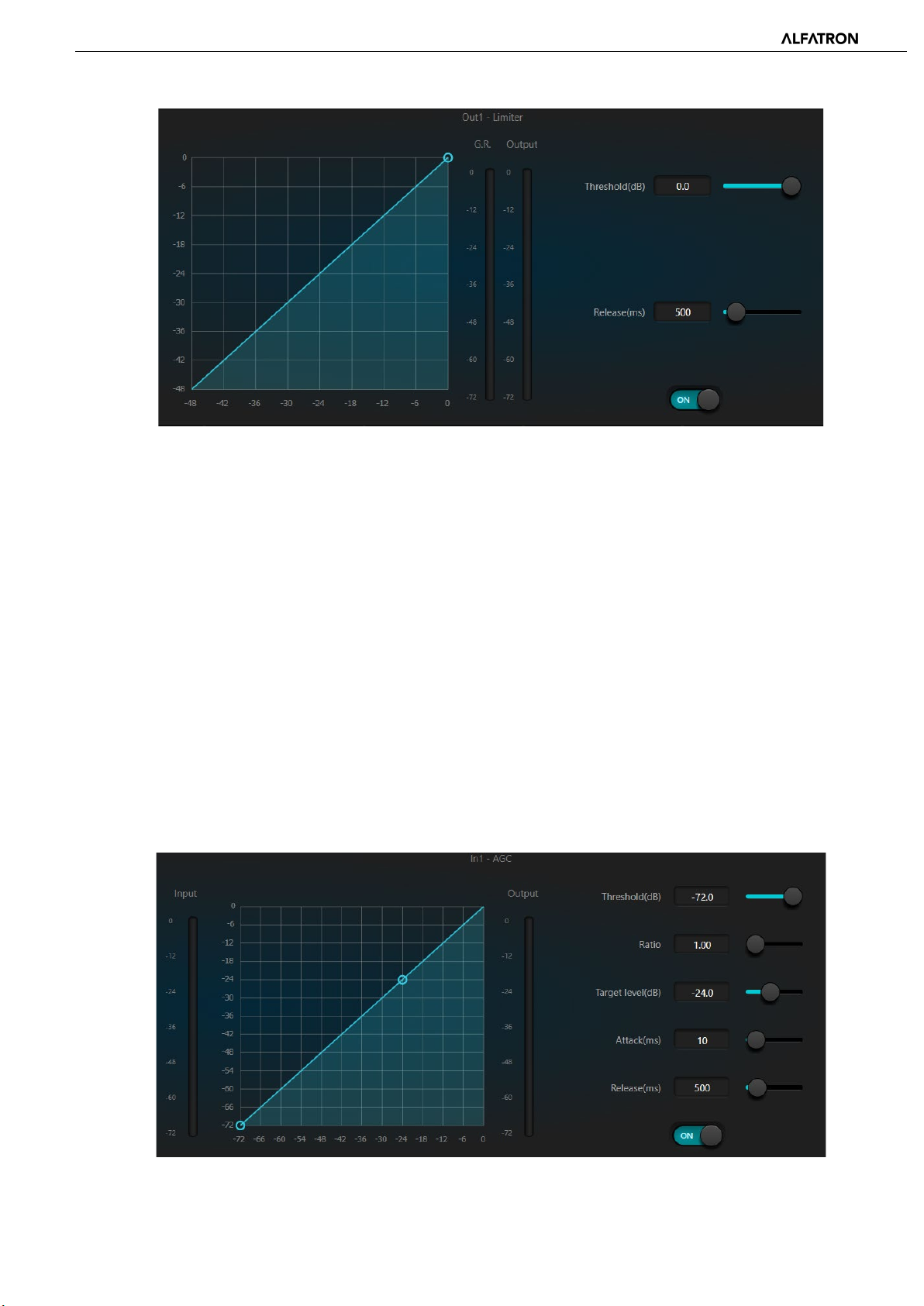
The limiter only has one key task: make sure that the signal will not exceed the threshold level in any way. By adjusting the
compressor's control parameters, its working modes will be very similar to those of the limiter. The core working principle of
a limiter is that it focuses on the signal below the threshold level as well as how the gain attenuation is produced before the
occurrence of overshoot signal. The limit period consists of two processing stages: during the first stage, there is a minor
limit, but the overshoot signal will not be processed; during the second stage, if there is overshoot signal, it will attenuate
with a very high ratio.
The limiter only provides two parameters: Threshold and Release Time. In terms of signal processing, occasional clipping will
be solved with a limiter, while the signal level will be attenuated in terms of frequent clipping.
3.3.4 Automatic Gain Control
Automatic gain control (AGC) is a type of compressor. Its threshold is set at a very low level with middle-to-slow attack time,
long release time, and low ratio. The purpose is to improve the signal with an uncertain level to a target level, while
maintaining the dynamic range at the same time. Most of the auto gain control includes silent detection to prevent the gain
attenuation loss during the silent period. This is the only function that distinguishes auto gain control from an ordinary
compressor / limiter.
Auto gain control may be adopted to normalize the level of CD players that play background music, foreground music and
music on hold, as to eliminate the changes in the level of some paging microphones.
-20-
Page 21
ALF-DSP88-U
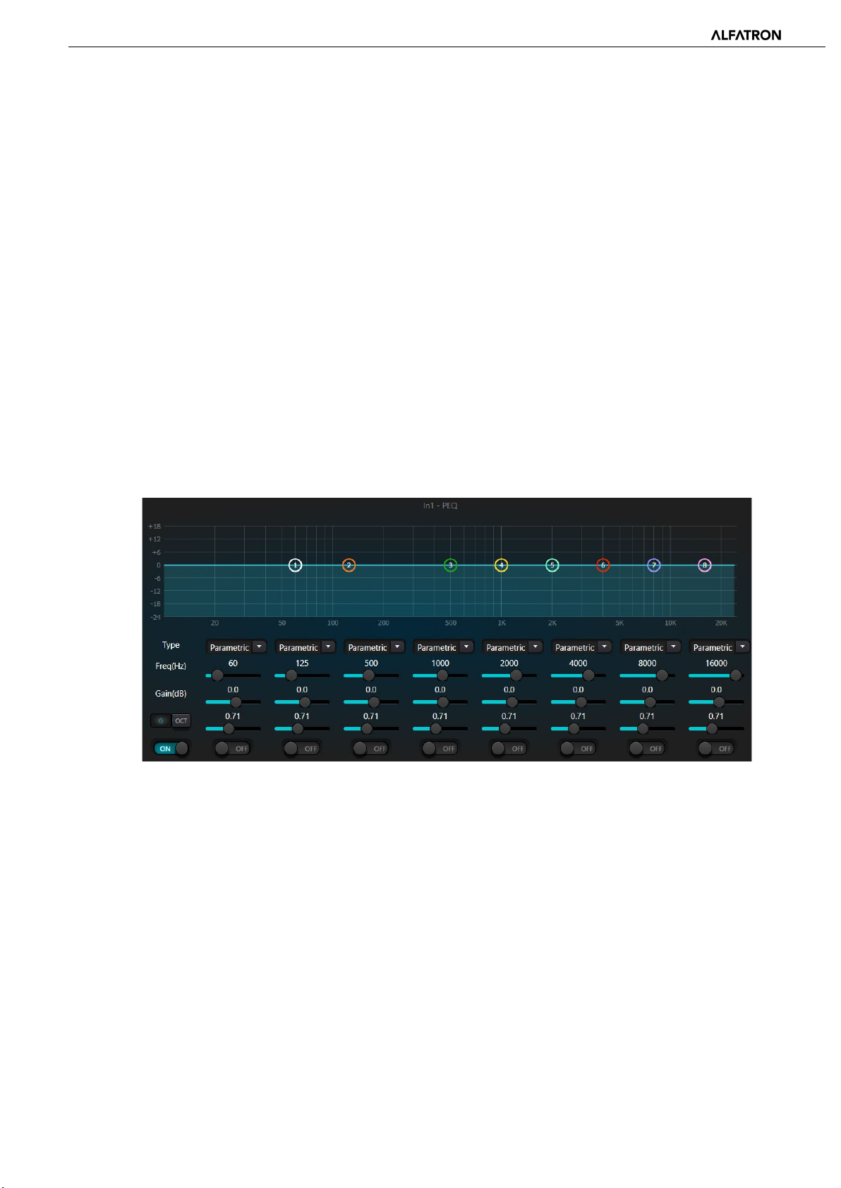
Auto gain control includes the following control parameters and switches:
Threshold: When the signal level is lower than the threshold, the input-to-output ratio is 1:1. When the signal level is
higher than the threshold, the input-to-output ratio changes with the ratio control settings. The threshold is set as the
background noise just higher than the level of input signal.
Ratio: It refers to the ratio of the changes in the level of the input signal higher than the threshold to the changes in the level
of the output signal.
Target Threshold: It refers to the level of output signal required. If the signal is higher than the threshold, the
controller will compress the signal in proportion.
Attack Time: It refers to the response time required to control the level higher than the threshold.
Release Time: It refers to the response time required to control the level lower than the threshold.
3.3.5 Equalizers
The equalizer is mainly used to correct the frequency range that is overemphasized or gets lost, no matter if it is wide or
narrow. In addition, the equalizer can also help us to narrow or widen the frequency range or change the amount of a
component in the frequency spectrum. To simplify, the equalizer can be used to change the tone of the signal.
The equalizer has the following control parameters:
Fig.3.6 Equalizer
Type: Parametric EQ is the default setting. High and low shelf filters and high and low pass filters can also be selected. Each
kind of filter has different forms to achieve different functions.
High and Low Pass Filter: The reference frequency of a pass-type filter is called the cut-off frequency. Pass-type filters allow
the frequencies on one side of the cut-off frequency to fully pass the filter; in the meantime, the frequencies on the other
side of the cut-off frequency are attenuated at a constant dB ratio per frequency octave. High pass filters allow the
frequencies above the cut-off frequency to pass and filter the frequencies below the cut-off frequency. To the contrary, low
pass filters allow the frequencies below the cut-off frequency to pass and filter the frequencies above the cut-off frequency.
High and Low Shelf Filter: High shelf filter means that the gain increases or attenuates for the frequencies above the set
frequency. Low shelf filter means that the gain increases or attenuates for the frequencies below the set frequency. The set
frequency is not 3dB cut-off frequency but refers to the center of the failing edge or rising edge of the filter. Q value affects
the peak and has a mathematical relation with the peak.
Frequency (Hz): Refers to the center frequency of the filter.
-21-
Page 22
ALF-DSP88-U
Gain (dB): Refers to the increased or attenuated decibel value of the gain at the center frequency.
Q: It refers to the quality factor of a filter. The adjustable range of the Q value is 0.02-50.
When the filter is set as a parametric EQ filter, Q value refers to the width of the bell-shaped frequency response curve on
both sides of the cut-off frequency.
When the filter is a high and low shelf filter or a high and low pass filter, if Q>0.707, there will be peaks in the filter
responses. If Q<0.707, the slope will become flatter, and the roll-off will occur in advance.
Each segment of the equalizer has a switch, which is used to turn on or turn off the corresponding segment. When turned off,
that frequency parameter settings are disabled.
The equalizer has a master switch, which is used to enable or disable the whole module.
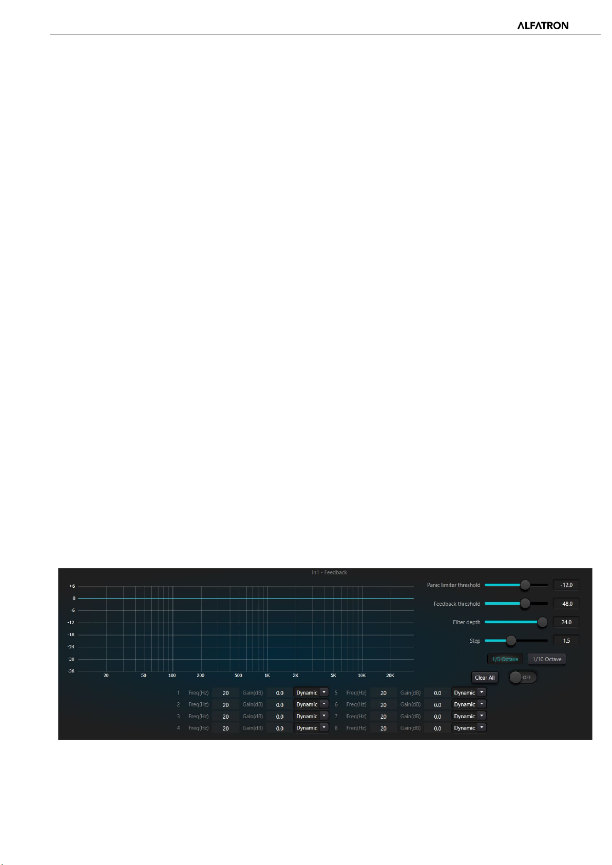
3.3.6 Feedback Suppressor
While using the feedback suppressor module, it is advised to remember that feedback suppression is not a replacement for a
good audio system design and commissioning. Traditional audio practices, such as limiting the number of open microphones,
minimizing the distance between sound source and microphone, positioning the microphone and loudspeaker to get
minimum feedback, and balancing the room to get a flat response, is the first step in setting up a good audio system. Later,
we can adopt feedback suppression to get additional gain. Feedback suppression cannot be used to magically solve a
system's design defects or improve the sound transmission gain in a way exceeding the system's physical limitations.
The feedback suppressor module automatically detects and inhibits audio feedback in the sound system. The module
distinguishes feedback from expected sounds based on the characteristics of the audio signals. When feedback at a certain
frequency is detected, a notching filter will be automatically added at the feedback point (frequency) to attenuate the signal
level at that frequency. During the first addition, the notching filter only attenuates the feedback a bit. If the feedback
persists, the notching filter will continue to attenuate the feedback in accordance with the preset parameters until the
feedback disappears or reaches the maximum preset parameter. Multiple user parameters can be used for accurate fine
tuning of the effects of the feedback suppression module.
The Feedback suppression filters may be locked up to prevent any change during operation. Alternatively, the filter settings
can be copied to a dedicated notching filter module (such as the parametric equalizer). The Eight filters can be set as auto
filters in an automatic cycle. In this way, those filters for temporary use can be removed.
Each input channel has a feedback suppression module. Use a mouse to navigate the input module and find the feedback
suppressor module or quickly enter the feedback suppressor module by clicking the shortcut key on the right. If the feedback
suppressor module needs to be enabled, activate the module to automatically detect the feedback point, and use a narrowband filter for elimination. Each feedback suppressor module has 8 narrow-band filters.
-22-
Page 23

ALF-DSP88-U
The feedback suppressor module has the following adjustable parameters:
Panic Limiter Threshold: According to this parameter, any level higher than the threshold is absolutely “feedback”. When a
signal level is higher than the feedback threshold, any of the following circumstances will occur; a) the output gain is
temporarily attenuated to control the speed of feedback; b) the output level is restricted to prevent out of control feedback;
c) the filter's sensitivity is increased for faster detection and feedback. Once the output level is lower than the threshold, the
gain will be recovered, and the sensitivity is restored to normal state. This value refers to the peak value of the digital range
signal. If the value is set as 0, this function is disabled.
Feedback Threshold: According to this parameter, "any level lower than the threshold is absolutely not feedback". This may
prevent the module from detecting feedback in a soft music or due low noise level.
Filter Depth: It refers to the maximum attenuation of a single filter. A shallow setting may prevent excessive frequency or
signal degradation caused by the notching filter to the original signal. A deep notching filter may cause worse feedback
control, especially in a large narrow resonance system.
Bandwidth: 1/10 and 1/5 Oct options can be chosen. A constant Q value is adopted. The filter will not become wider due to
the increase of depth. It is recommended to use the filter in the phonetic environment. In the case of frequent feedback, the
bandwidth is set at 1/5 Oct because it has wider bandwidth and greater influence.
Preset: There are four built-in presets: "big music room", "small music room", "big voice room" and "small voice room".
These four presets apply to the default settings for most applications.
Notching Filter's Auto Mode: When Auto mode is set for the notching filter and after eight filters are in use, when new
“feedback” is detected, the module will “check” the auto filters and use it to inhibit the new feedback. Each notching filter
has three modes: auto, manual and fixed modes. When Manual mode is set for the filter, the gain can also be manually set.
When Fixed mode is set, the filter always works and will not be occupied by new feedback points; it still works when being
rebooted. If you need to save these feedback parameters, please click to save the preset button.
Clear All: Click the button to instantly clear all filters. It will clear up all feedback points detected previously. This operation is
generally done when recommissioning the feedback module.
Feedback suppression can be used as a tool during system commissioning to identify feedback points or as a preventive
measure during normal operations. If you want to get higher system transmission gain and feedback suppression, it is
recommended that you debug the system by following the steps below:
(a) Reduce the system gain, and use the "Clear" button to reset all filter parameters
(b) Set up fine-tuned parameters for the feedback suppressor module. Also, decrease the panic threshold to reduce the
feedback level.
(c) Open all microphones, and slowly increase system gain until feedback occurs. Stop increasing system gain when
the feedback occurs.
(d) Wait for the feedback suppressor module to take effect; after the feedback disappears, continue to increase gain.
(e) Repeat the operation until the system reaches the required gain or until all filters are fully distributed
(f) Change the panic threshold to a maximum level just higher than the expected non-feedback signal.
At this time, if needed, you may set Fixed mode for each filter or save the dynamic status to deal with possible feedback
during the normal operation. Additionally, you may copy the filter to a notching filter module (such as the equalizer). In this
way, you may add more feedback filter capacity.
If a speaker is included among the devices used, it is recommended to use a compressor / limiter module for additional
protection. You may set an appropriate limiter to make sure that the speaker will not get damaged even if all notching filters
are used up, or the feedback inhibitor cannot effectively control the feedback, such as in the case of excessive system gain.
-23-
Page 24
ALF-DSP88-U
the same working mode. It is suggested that the value be set at or around 2.0.
3.3.7 Auto Mixer
In a conference room, if several microphones are opened to the same gain level and there is only one person speaking, the
audio pickup of the microphone may be not clear. Other microphones will pick up noise and reverberation in the room.
When these signals are mixed with the desired ‘speech’ signals, audio output quality may be greatly reduced and become
un-intelligible. In addition, the whole audio signal chain may be over energized by excessive gain and could start feeding
back, result in a feedback loop, or ‘ringing’ sound. To solve the issue, other unused microphones should be closed or ‘muted”
when not in use. The auto mixer is used to automatically open and close microphones based on signal input level.
There is a built-in gain share auto mixer inside the processor. It supports up to 8-channels. There is also a direct output at
each channel of the auto mixing matrix, which is only influenced by channel mute and bypasses the auto mixer functions like
auto gain and channel fader. Channels suitable for fixed volume like background music need to be kept at a fixed level
without being controlled by the auto mixer. For example, it will keep a microphone normally open. Its gain will then not be
influenced by the auto mixer. At this point, users may directly adjust the output of the channel in the matrix router as well as
turn off the auto mixer button of the channel. Its gain will not be adjusted and gains at other channels will not be influenced
by the signal level at the channel.
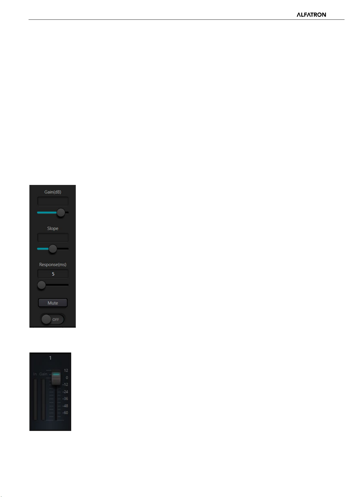
There are two groups of control parameters in the auto mixer module: main control parameters and channel control
parameters.
(1) Main (Global) control parameters
Click the ON / OFF button to turn the auto mixer on or off.
Gain: Controls the main output volume of the auto mixer
Slope: The slope control influences the attenuation of lower levels. If the slope is high, the
attenuation of lower-level channels will rise. The slope control and the ratio control at the
expander has
If it is set at 1.0, the effect is equal to closing the auto mixer at all channels. If it is set at 3.0,
the action will result in larger gain adjustment, which may bring unnatural volume levels. The
bigger the value, the more the channel is opened and the more the total attenuation. When
the slope is set at 2.0, ideal gain sharing may be realized, so it is the preferred value to use.
Response Time: Faster response time may ensure that the first letters of spoken words are
not cut off. Slower response time allows smoother operation. Practice shows that the best
effect will be produced when response time is between 100ms and 1000ms. The design of
auto gain aims for faster microphones switching. Therefore, first letters of spoken word will
not be cut off even if the response time is set to 100ms. If it is set at several seconds, then
there will be a longer hold time of the response time of the auto mixer, previous active
channels will be saved at open status for several seconds.
(2) Channel control parameters
Auto Mixer: Each channel has an auto mixer on / off button which must be turned
on for that channel to participate in the auto mixer. When in Off mode, that channel
will not participate in the auto mixer.
Mute: Both the channel mute and volume fader are post the auto gain processor. If
the channel level is higher, the level gain of other channels may also be reduced
even if the channel mute is on.
Gain: The Gain fader adjustment may increase / decrease the volume amount of that
channel in the auto mixer.
-24-
Page 25

ALF-DSP88-U
the value, the higher the
Priority: Priority settings may give priority treatment to high priority channels over
low priority channels, and therefore the auto mixer algorithm will be affected
accordingly. Priority ranges from 0 to 10. The higher
priority.
Both the channel mute and fader are post auto gain. Any adjustment made towards these two parameters won’t influence
the operation of the auto mixer. For example, If the channel level is higher, the level gain of other channels may also be
reduced even if the channel mute is on. Channel mute must be turned on and the auto mixer shall be turned off to set signal
mute and prevent its influence on the auto mixer. The mute button at each channel and directly controls output mute when
mixing sound. Channel faders also control sound mixing level and direct output level of channels. Click the textbox and input
a dB value to control channel level precisely.
Priority control allows high priority channels to override low priority channels, and thus the auto mixer algorithm will be
affected. Priority value can be set from 0 (the lowest priority) to 10 (the highest priority), and the default value is 5 (standard
priority). Users may use the slider or click the textbook to input a specified priority between 0 and 10. Increasing the value
means increasing priority.
If two channels have the same signal level, then the channel with higher priority will receive more auto gain. If there is oneunit difference in priority level between them, then the channel with the higher priority level will get an extra gain of 2dB
(supposing the slope of the two channels are set at 2.0). For example, if channel 1 and 2’s priorities are respectively set at 6
and 3, and the input level of those two channels are the same, then Channel 1 will receive 66dB gain more than Channel 2.
During operation, please note that the slope setting of the main control parameters influence gain difference brought by the
priority weight of channels. If the slope is set at 3.0, then one priority level difference will result in a gain difference of 4dB.
Note: In some cases, be very careful when using wide priority differences between channels, such as a priority of 0 and 10. If
channels with ultra-high priority recognize signals like background music from a loudspeaker, then it is possible for them to
mask channels with lower priority. The effect will get worse if the slope is higher too. If the issue occurs during installation
and commissioning, users may consider installing a noise gate or expander between the auto mixers of the highest priority
channels. Also, consider setting a threshold at a value that it won’t be opened by the noise gate or expander.
3.3.8 Acoustic Echo Cancelation
Acoustic Echo Cancelation (AEC for short) is used in audio / video conferencing to facilitate full duplex communication. The
AEC module increases the remote speaker’s phonetic intelligibility by cancelling out or removing unwanted acoustic echo
generated in the local room’s audio system (between the microphones and speakers).
Echo cancellation module for remote calls can be used to carry out local amplification of remote voice signals and attenuate
the interference caused by acoustic echo. Its basic operation principle is simulating echo channel, estimating possible echo
generated by remote signals and then minus the estimated signal from input signal of microphones, and thus there will be
no echo generated in input voice signal to achieve the goal of cancelling echo.
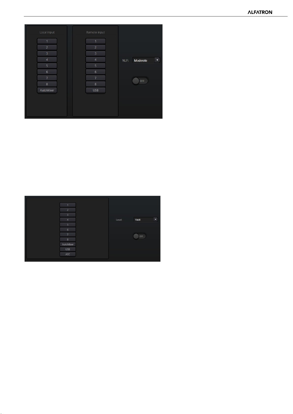
There is only one echo cancellation module in the DSP Controller. Two local inputs and remote output mixers are preset to
realize multichannel signal participating in echo cancellation as shown in figure.
One parameter can be adjusted, namely the Non-linear filter (NLP). There are three preset filters to choose from:
Conservative, Moderate and Aggressive can be selected to determine the acoustic echo suppression level.
-25-
Page 26
ALF-DSP88-U
of noise
noise. The bigger the
Note: The settings of the Acoustic Echo Cancellation module can be used cooperatively with the matrix module to determine
signal routes.
3.3.9 Noise Suppression
The Noise suppression module is used to remove non-human voice interference noise. It may distinguish human voice from
non-human voice and treat the latter as noise. After processing, only human voice audio signal is passed to the output
routing.
There is only one Noise Suppression m
channels to participate in the noise cancellation processor as shown in the below figure.
odule in the DSP Controller. Multichannel mixers are preset to realize multiple
Suppression level: There are three levels
suppression including: Mild (-6dB), Medium (-10dB) and
Aggressive (-15dB). dB here refers to the reduction in
decibel level of the suppressed
value, the more degradation of voice signal is caused,
therefore use noise suppression very cautiously.
3.3.10 Matrix
The audio Matrix has dual functions including routing and mixing. As shown in the figure below, the horizontal axis indicates
the input channels, and the vertical axis indicates output channels. One-to-one routing of input to output is set as the default
settings. As an example, to mix and route audio signals of channel 1 and channel 2 and then output both select OUT1 on
both IN1 and IN2. If input 1 and 2 participate in auto mixing, then output 1 will not be influenced by the auto mixer. In other
words, after setting auto mixing, echo cancellation and noise suppression modules, routing needs to be set in the matrix
from the correct input sources, like auto mixer, AEC, or ANS to get the correct signal routing.
-26-
Page 27
ALF-DSP88-U
3.3.11 High and Low Pass Filter
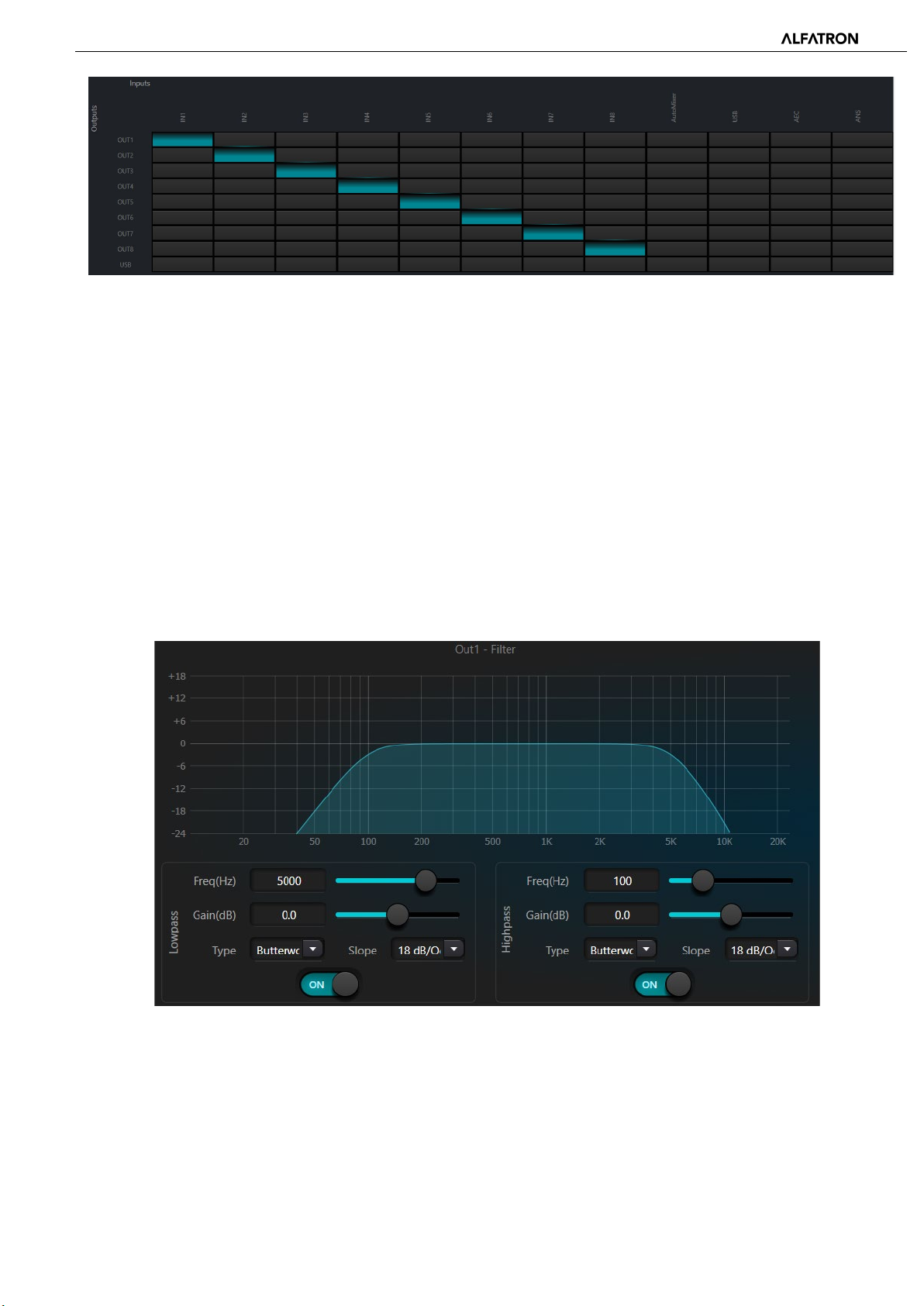
Each output channel provides a pass-through filter module which consists of high-pass and low-pass filters. Each filter has
four parameters to adjust as follows:
Frequency: This sets the cutoff frequency of each filter. The cutoff frequency of Bessel and Butterworth are selectable in -3
dB steps, and the cutoff frequency of Linkwitz-Riley are selectable in -6dB steps.
Gain: The Gain setting influences the increase and attenuation of each filter band.
Type: There are three types of filters to choose from; Bessel, Butterworth, and Linkwitz-Riley. Butterworth has the flattest
knee on the passband.
Slope: Slope refers to the attenuation values of the transition zone of the filter. There are a total of 8 attenuation values
including 6, 12, 18, 24, 30, 36, 42 and 48dB/Oct. For example, 24dB/Oct indicates that the attenuation range is -24dB for
each octave of frequency in the transition zone.
Select the On / Off button to activate or deactivate the high-pass or low-pass filters individually.
-27-
Page 28
ALF-DSP88-U
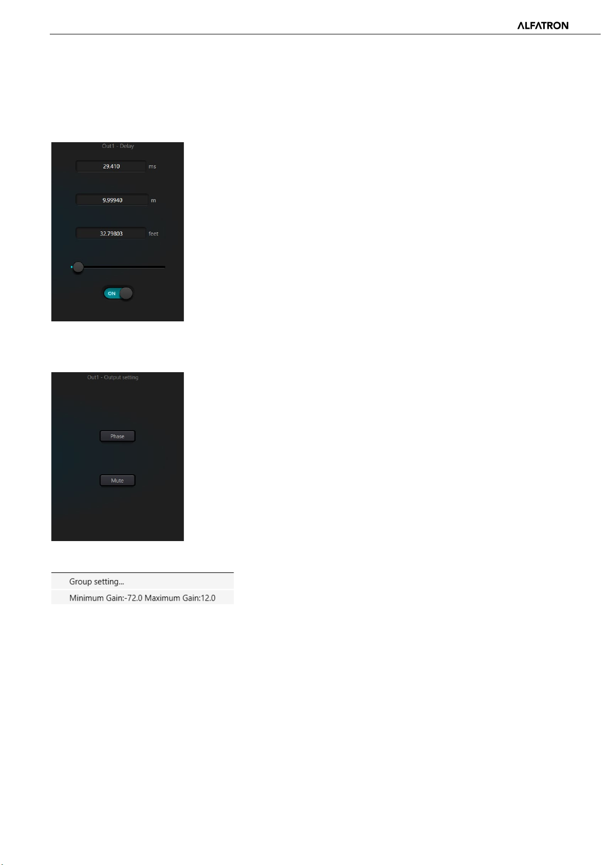
3.3.12 Delay
The Delay module is used to add delay to the output audio signal. This can be used to align audio signals in physical
time.
Activate button: Turns On / Off the delay module and inserts it into audio
signal path to increase fixed delay time for signals.
Millisecond (ms): Sets the delay time in milliseconds. The value ranges from 1
to 1200 milliseconds. Both meter and feet are alternate units provided to
milliseconds to set a delay time based on physical distance.
3.3.13 Output
Phase: 180-degree audio signal phase inversion.
Mute: Set output mute/unmute.
Users can use right button to set part menu at output channels, which can be carried out based on requirements.
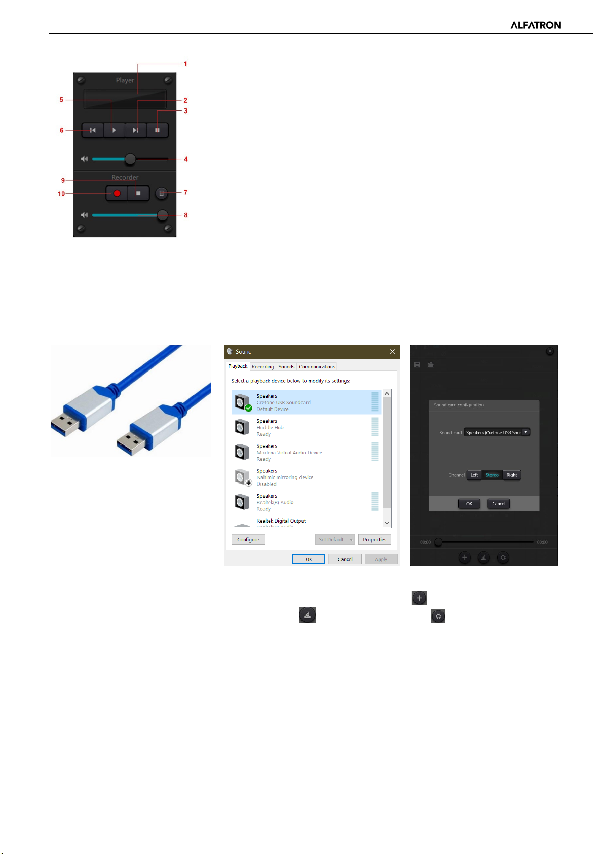
3.3.14 USB interface
The USB interface is used to carry out two functions, recording and as audio interface for unified Communications using
personal computers. After going through echo and noise cancellation modules, the USB interface may be accessed by unified
communications software when connected to a computer.
-28-
Page 29
ALF-DSP88-U
① Song playing information, double click to enter playlist
② Next song
③ Pause
④ Song volume adjustment
⑤ Play
⑥ Prev. song
⑦ Sound recording list
⑧ Sound recording volume adjustment
⑨ Stop recording
⑩ Start recording
Soundcard Setting
USB cable with double ends of Type-A can be used to connect DSP processor and computer host. For initial connection, the
“Found New Hardware” windows will pop up on the computer screen, and the driver will be installed automatically. After
installation, the USB soundcard will be accessible in the computer soundcard list as shown in the figure below. Users may
select ‘Cretone USB Soundcard’ in the Sound Settings panel of the computer for both Playback and Recording.
Users may also playback audio files loaded manually in the on-board playlist from the connected computer. Users may also
directly open them when using the device next time. As shown in the figure, click at the bottom of the playlist to open
file folder and select the audio files to be played, press to clear the playlist and to enter the settings of the USB
interface.
-29-
Page 30
ALF-DSP88-U
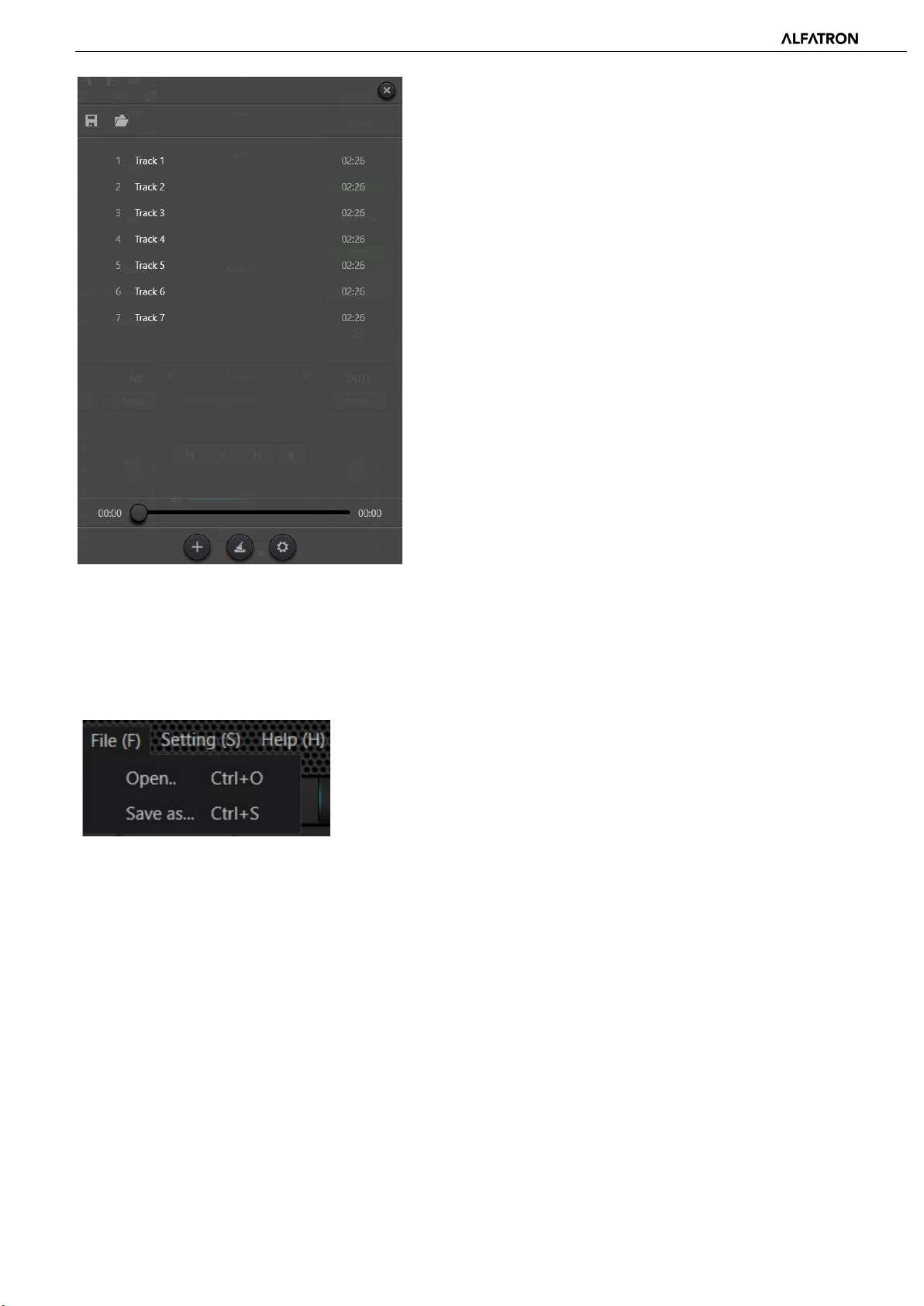
3.4 Setting Menu
3.4.1 File Menu
In offline mode, click the pop-up file dialog and open an existed default document with suffix *.uma, or right click on the
default document to open DSP.exe.
“Save as” refers to saving presets on the application to local hard risk to realize easy copy and store.
-30-
Page 31
ALF-DSP88-U
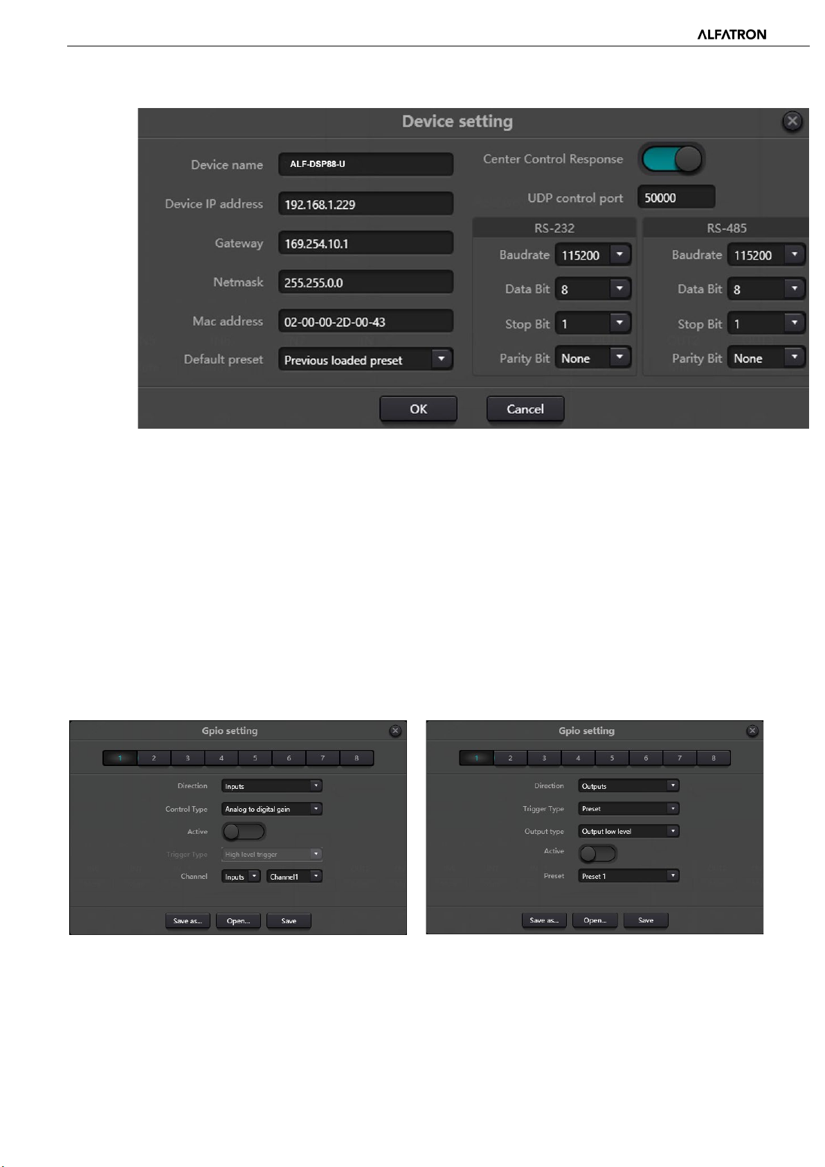
3.4.2 Device Setting
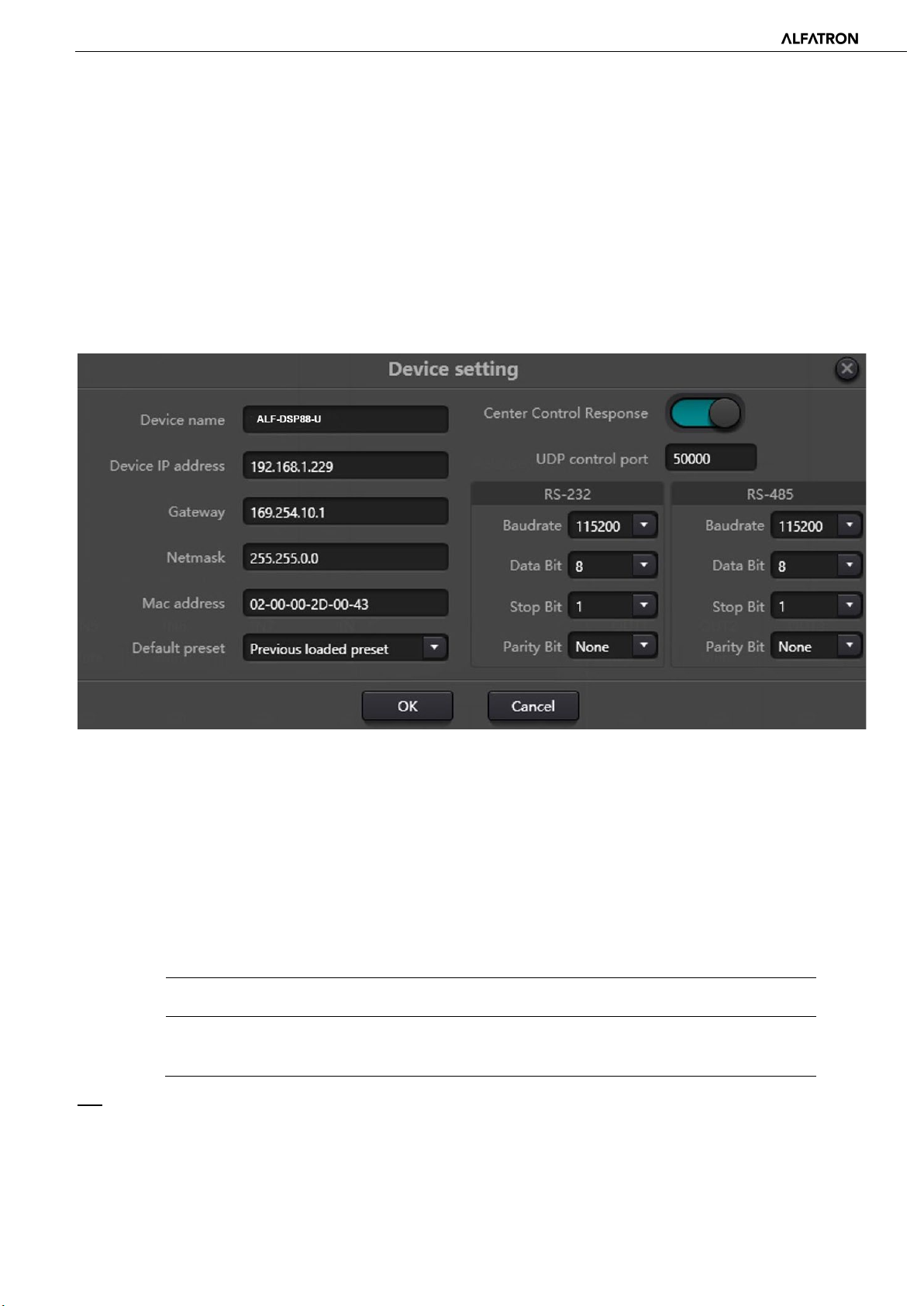
Information like device name, network address and serial baud rate can be set under device setting. The maximum length of
the device name is 16 characters.
Default startup: Two startup preset modes are available for selection. One is any preset from 16 presets acting as startup
preset. Each boot will start with it. Another is selecting previous upload preset and taking the last preset before power
outage as the preset for next startup.
3.4.3 GPIO Setting
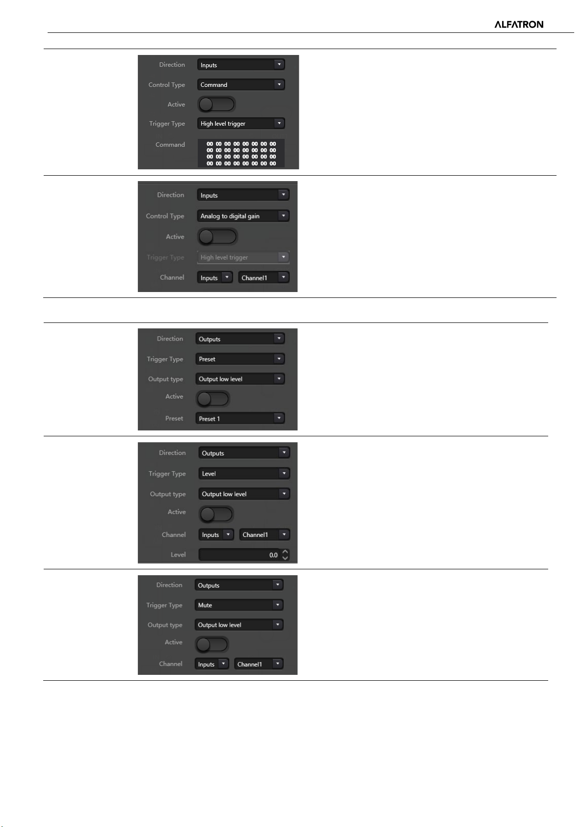
Open the software interface of GPIO settings. The device has total 8 GPIOs that allow independent input or output
configuration.
Input GPIOs have preset, router, gain, mute, command, and analogue-to-digital gain as control options.
Output GPIOs have preset, level, mute, and command for selection as control options.
-31-
Page 32

ALF-DSP88-U
falling edge trigger, rising
It will change to preset when jump type of
Input GPIO Setting
Preset
Routing
Gain
Trigger types: High level trigger, Low level trigger, High
level trigger / Low level trigger cancellation, Low level
trigger, High level cancellation,
i.e., rising edge / falling edge trigger / rising edge trigger,
falling edge cancellation /
edge cancellation
Preset:
hardware GPIO port and trigger type of software setting
are consistent.
Trigger types: Same as above
Input and output: Select input channel routing
corresponding to output channel.
Executes mixing / cancel mixing action when the trigger
condition is satisfied.
Trigger types: Same as above
Mute/ Unmute
Channels: Select input or output channels
Step: Level increase / decrease in 0.1dB steps based on
original channel gain.
Trigger types: Same as above
Channels: Select input or output channel
-32-
Page 33
ALF-DSP88-U
potentiometer externally. It may adjust input or
output channel. Preset
n the contrary, the opposite level will be output
Command
Analogue-todigital Gain
Output GPIO Setting
Preset
Trigger types: Same as above
Command: The command code will be sent via RS232
when the trigger condition is satisfactory
Analogue-to-digital gain is very useful when connecting
a
output channel gain. It looks like a rotary encoder. The
difference between them is that a potentiometer is
analogue and adjusts voltage and current while an
encoder is digital and transmits binary codes of 0 and 1.
Output types: High level / Low level
Level
Mute
Preset: Corresponding GPIO port outputs high level or
low level when changing to it.
Output types: High level / Low level
Channels: Appointed input or output channel
Level: GPIO outputs high / low level when appointed
channel level reaches preset level threshold.
Output types: High level / Low level
Channel: Appointed input /
high / low level is output when the channel is muted.
O
when cancelling mute.
-33-
Page 34
ALF-DSP88-U
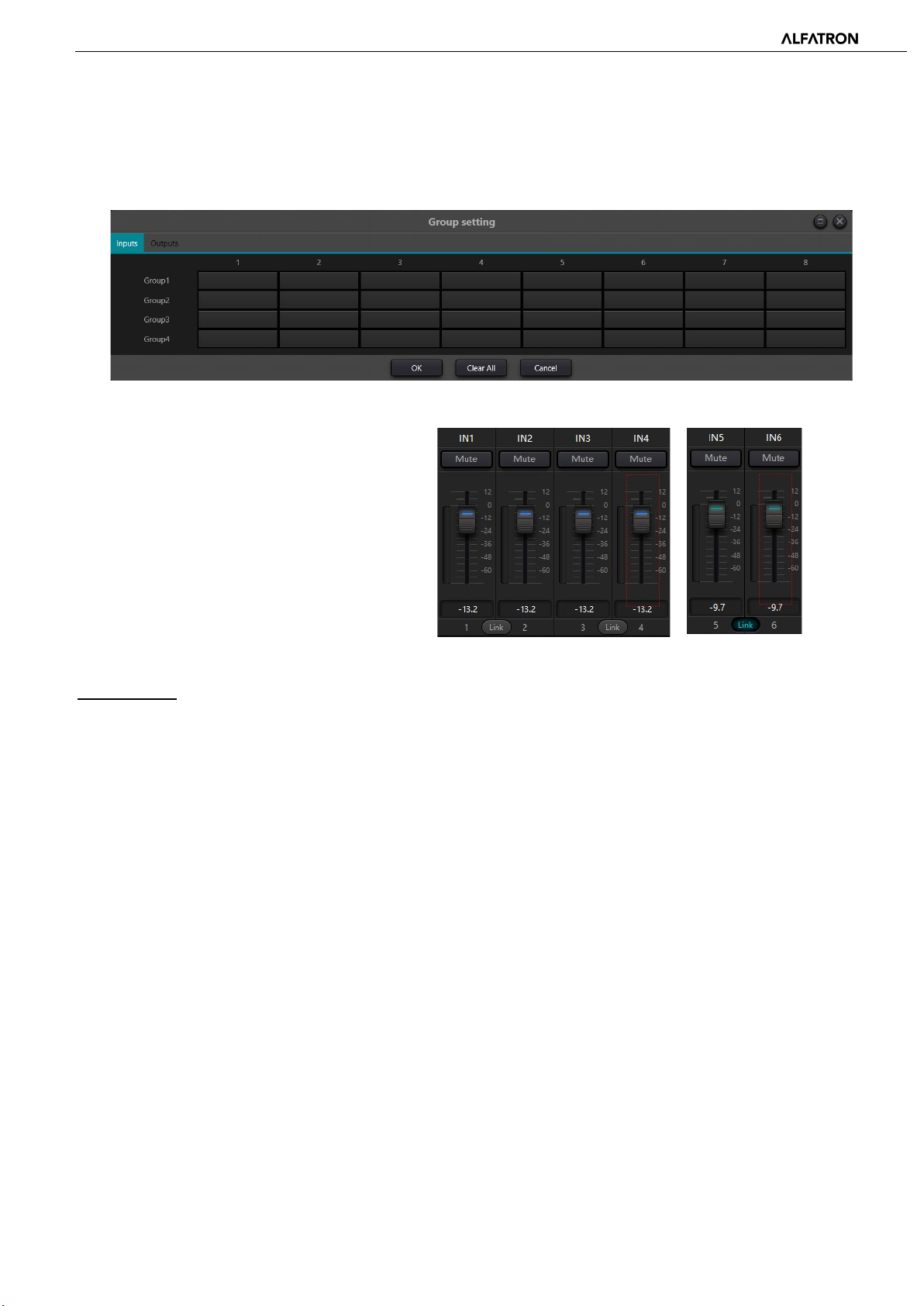
device maximum
into one group which will be differentiated by a
3.4.4 Group Setting
The interface for group assignments contains two sections including input and output labels. a Maximum of 4 groups are
available. A channel can only participate in one group. In each same group, the channel volume adjustment and mute are
synchronous. Other module parameters are not synchronized, which is the biggest difference between the Group
assignments and the stereo ‘Link’ option.
There are 4 groups in total. 1number of channels can be selected for each group.
The maximum number of channels is determined
by the device type you purchased. Channels are set
color difference of the volume slider in the main
interface.
Group vs. LINK
The relationship between groups and link: The channel participating in a group will not participate in a ‘LINK’, which means
group priories are higher than LINK. The difference between Groups and LINK is that Groups can only control channel gain
and mute, while LINK links all parameters at the channel.
-34-
Page 35
ALF-DSP88-U
3.4.5 Panel Setting
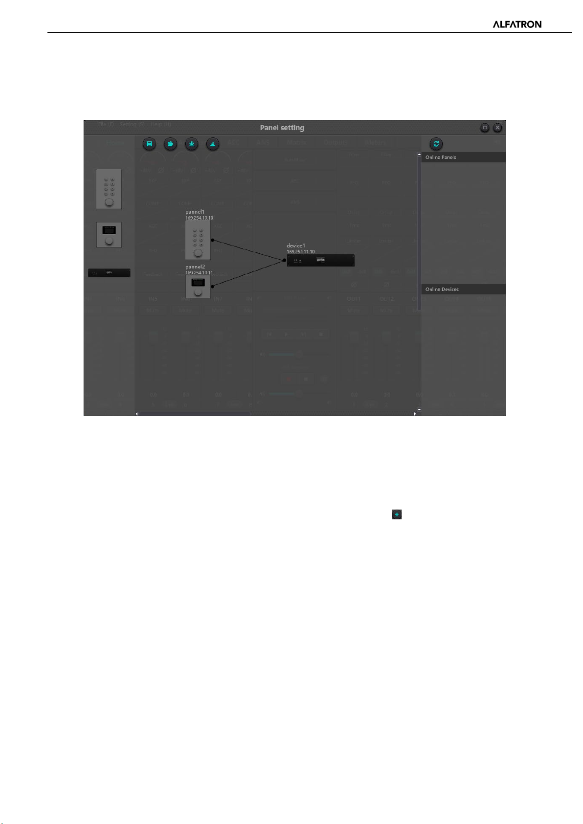
Panel setting includes two panel types which are a 8-button panel with Volume control and an OLED panel. Use virtual cables
to connect multiple physical online panels with the online DSP device via panel settings, to configure the panels for
controlling selected DSP features.
Offline device: In offline edit status, the commissioning engineer configures the panel parameters locally, and then
downloads it to the online panel. The panel can then be edited directly online. Drag an offline device from the column of
online panels to the panel design area and then double click to edit it.
Please note that there is a small circle on both panel and device. Click the circle and then draw a line, select target device,
the connection between the two devices is established this way.
Double click the panel in design area to enter the panel’s configuration interface. The configuration of the two panels are
described below. After completing configuration, click the toolbar download icon to download the panel configuration to
the hardware panels.
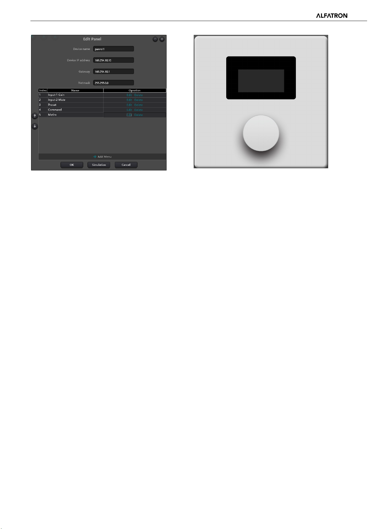
OLED Screen:
The OLED screen consists of a 1.3” OLED screen and Rotary encoder. The OLED screen display is organized according to the
function assigned. There are three types of functions including menu, buttons, and presets. Double click the OLED screen in
the design area to enter its setting as shown below.
-35-
Page 36
ALF-DSP88-U
Click "add menu" to access the pop up menu selection box, choose the corresponding function and confirm it. After finishing
the settings of the software menu configuration, click on the toolbar download icon to download the configuration to the
hardware panel.
Operating the panel:
1. The panel displays name and IP address on main interface. Turn the Rotary Encoder left or right to change menus.
2. Press the Rotary Encoder to enter and display the second row of the menu. The interface starts to flash, which indicates
that it entered edit mode of that menu.
3. Turn the Rotary encoder left or right to change value.
4. Press the Rotary Encoder again to exit the edit mode and go back to the main menu.
Key Panel:
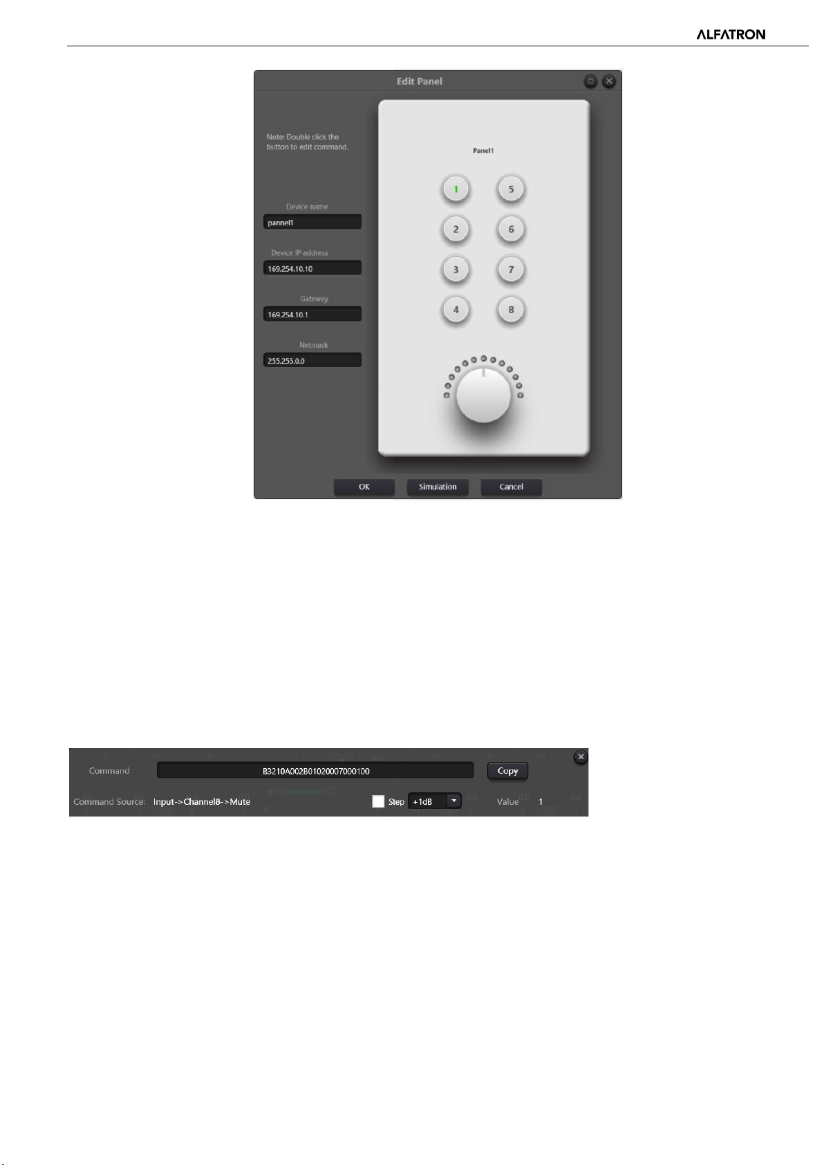
There are eight keys and one Rotary Encoder on the key panel. The Rotary Encoder is used to adjust gains, and the eight keys
can be used to achieve different functions through programming. There are four types of key functions, including volume
adjustment, mute, preset, and command. Drag an item into the function area to assign the key and complete the
programming steps of the key.
After completing all programming, users may use the emulation button to check the configuration of the panel is correct.
-36-
Page 37
ALF-DSP88-U
Panel operation and Indicators:
1. Button remains illuminated, indicating that it is configured with a mute function.
2. Button keeps flashing, which indicates that the button is configured with gain function. The configured Rotary Encoder
adjusts the gain of the assigned channel. 13 indicators around the Rotary Encoder indicates gain level. They are on or off
with gain level set. When all 13 indicators are off, it indicates a gain of -72dB while all on indicates a gain of 12dB.
3. A momentary flash when pressing the button indicates the button is configured for preset or command recall.
Command functions data strings comes from the central control command. Please refer to section 5.
3.4.6 Help Menu
(1) Central command
Open the central control command window and select the parameter to be controlled on the DSP GUI interface. The window
will display the current command immediately. Copy the command and then use UDP or RS232 to send the command to the
device form external control interface.
(2) Device upgrade
Device upgrades can be carried out through UDP. Connect the device, click setting-help-device upgrade. A file choice pop-up
box will appear, navigate to, and choose the processor upgrade file (*.bin). Execute the update.
(3) About
Display version number, tech support contact information and copyright info., etc.
-37-
Page 38
ALF-DSP88-U
4. Control
4.1 External Control Programmer
The External control programmer supports UDP and RS232, and controls protocols for all control parameters of the
processor, including module parameter controls, parameter acquisition, and preset calling.
When UDP controls are used, the default port is 50000. Ports can be set in “Device Setting” in the DSP software.
When using RS232 controls, the default baud rate is 115200, data bits is 8, stop bit is 1, and parity set to ‘None’. Similarly,
they can be set in “Device Setting”. The interval between messages must be more than 100ms for RS232 command sending.
If central control needs feedback and acknowledgement, please turn on ‘central control response’ in “Device Settings”.
4.2 Control Protocol
Because of historical reasons, the latest control protocol adopts variable-length and is fully compatible with old fixed-length
control protocols. In protocols, the fourth byte is used to distinguish versions. 0- indicates V1 version (previous versions) and
1- indicates V2 version (current protocol version).
The difference between V1 and V2 is that V1 may control all processing module parameters, but one command can only
control one parameter. If a parameter is needed to control continuous multiple channels, then V2 version must be used. In
other words, in a condition that users need to press one key on the key panel to trigger GPIO output high- / low-level of
devices, or send a command via RS232 / RS485, then V2 version will be the best choice.
Software coding rules (total 12 bytes)
byte1 byte2 byte3 byte4 byte5~132
0xb3 Message
Type
V1:
Information types (byte2): There are three information types including 0x21 (parameter controls), 0x22 (parameter
acquisition) and 0x13 (scenario switch).
Length Version
No.
Data
-38-
Page 39

ALF-DSP88-U
Length (byte3): invalid.
0x21 (parameter control): Data byte 5 thought 12 are respectively:
byte 5~6 byte 7~8 byte 9~10 byte 11~12
Module ID Parameter Type Parameter 1 Parameter 2
Please refer to Appendix A to get the distribution of Module ID (byte 5 ~ 6).
Please refer to Appendix B for Parameter types (byte 7 ~ 8).
When Parameter 1 (byte 9 ~ 10) has only one parameter, then only parameter 1 is valid, such as control compressor switch.
Parameter 2 (byte 11 ~ 12) only valid when there are two parameters, such as control output channel 1 mute. Parameter
value 1 shall be filled in input channel number from 0. Parameter value 2 shall be filled in 1 (mute).
Exception: Matrix routing has three parameters. The first one is input channel number, the second one is output channel
number, and the third one is routing switch. At this point, byte 9 of parameter value 1 shall be filled in input channel
numbers, byte 10 shall be filled in output channel number, and parameter 2 shall be filled in routing switch.
0x22 (Parameter Acquisition):
Parameter acquisition rules are the same with parameter controls. The difference between them is values acquired shall be
filled in parameter 1 and parameter 2.
0x13 (Scenario Switch):
Users only need to fill scenario numbers (0 ~ 15) in byte 5 and 0 in byte 6 ~ 12.
Note: Central control command of V1 version can acquire code through software menu bar of PC. For customized
development, please use this protocol rule.
V2:
Message types (byte 2): There are three message types (byte 2) including 0x21(parameter controls), 0x22(parameter
acquisition), 0x13 (scenario switch), 0x74 (other controls), and 0x6e (Dante routing).
Length (byte 3): Fill in corresponding data section length based on information type. The length can be longer when actual
sending is carried out. Total data volume can be found through adding 4 byte header information to data length.
1. Parameter Control (0x21)
At this point, the formats of data section are as follows.
Byte 5 Byte 6 Byte 7 Byte 8 Byte 9 ~ 72
Input / Output Start Channel End Channel Parameter Type Parameter Value
Byte 5: It indicates control input or output channel, 0x2- input channels and 0x1-output channels
Byte 6 - 7: They indicate start and end channel numbers. Channel numbers start from 0.
Byte 8: This kind of parameter is the same with V1 version. Please refer to Appendix B.
Byte 9 - 40: Fill in parameter values of start to end channels. It shall be filled in from the ninth byte. Each parameter value
shall take two bytes.
2. Parameter Acquisition (0x22)
Data section format is the same with parameter controls. Parameter values may not be filled in. Acquired parameters will be
filled in this position.
3. Scenario Switch (0x13)
-39-
Page 40

ALF-DSP88-U
Byte 5: Fill in scenario numbers (0 - 15).
Byte 6 - 8: Fill in 0.
4. Other Controls (0x74)
Other controls include but not limited to GPIO, RS232, RS485, and central control replies. The protocol formats are as follows:
GPIO:
Byte 5 Byte 6 Byte 7 Byte 8 Byte 9 Byte 10 Byte 11 Byte 12
Control
Type
The controlling type for Byte 5 is 1.
The data length of Byte 6 is fixed as four bytes.
Byte 9 GPIO direction, set input or output. Value 0 indicates input, and value 1 indicates output.
Byte 10 - 11 start GPIO and end GPIO. DSP devices have eight GPIOs in total, which are indicated with number 0 - 7.
Byte 12 is determined according to Byte 9 GPIO direction. The field shall be filled in high (1) / low (0) level for output settings.
The field is a return field to read GPIO level value on devices for input settings.
RS232 / RS485:
Byte 5 Byte 6 Byte 7 Byte 8 Byte 9 - 132
Control Type Data Length Reserved Reserved Data
Byte 5 is 2 for RS232 control, and 3 for RS485 control.
The data length of Byte 6 refers to data length that shall be sent via RS232 / RS485 currently.
Byte 9 - 132 shall be filled in data sent by RS232 / RS485.
Central control replies:
Data
Length
Reserved Reserved GPIO Direction Start GPIO End GPIO Value
Byte 5 Byte 6 Byte 7 Byte 8 Byte 9
Control Type Data Length Reserved Reserved Reply Switch
Byte 5 control type is 4.
The data length of Byte 6 is 1.
When Byte 9 is 1, it means turning on central control replies switch; and 0 means turning off replies.
4.3 Serial Port-to-UDP (RS232 To UDP)
DSP devices support RS232 translating into UDP. The protocol formats are as follows.
4bytes prefix 4bytes 2bytes 1byte 1byte 128bytes
UDP: IP Address Port Data Length Reserved Data
After receiving the protocol format data packet, RS232 sends data in the protocol to appointed IP addresses and devices at
ports.
-40-
Page 41
ALF-DSP88-U
For example, when sending data “HELLO DSP” to device port 50000 of device ”192.168.10.22”, the protocol commands are
as follows:
4 bytes prefix 4 bytes 2 bytes 1 byte 1 byte 128 bytes
0x3a504455(’:PDU’)
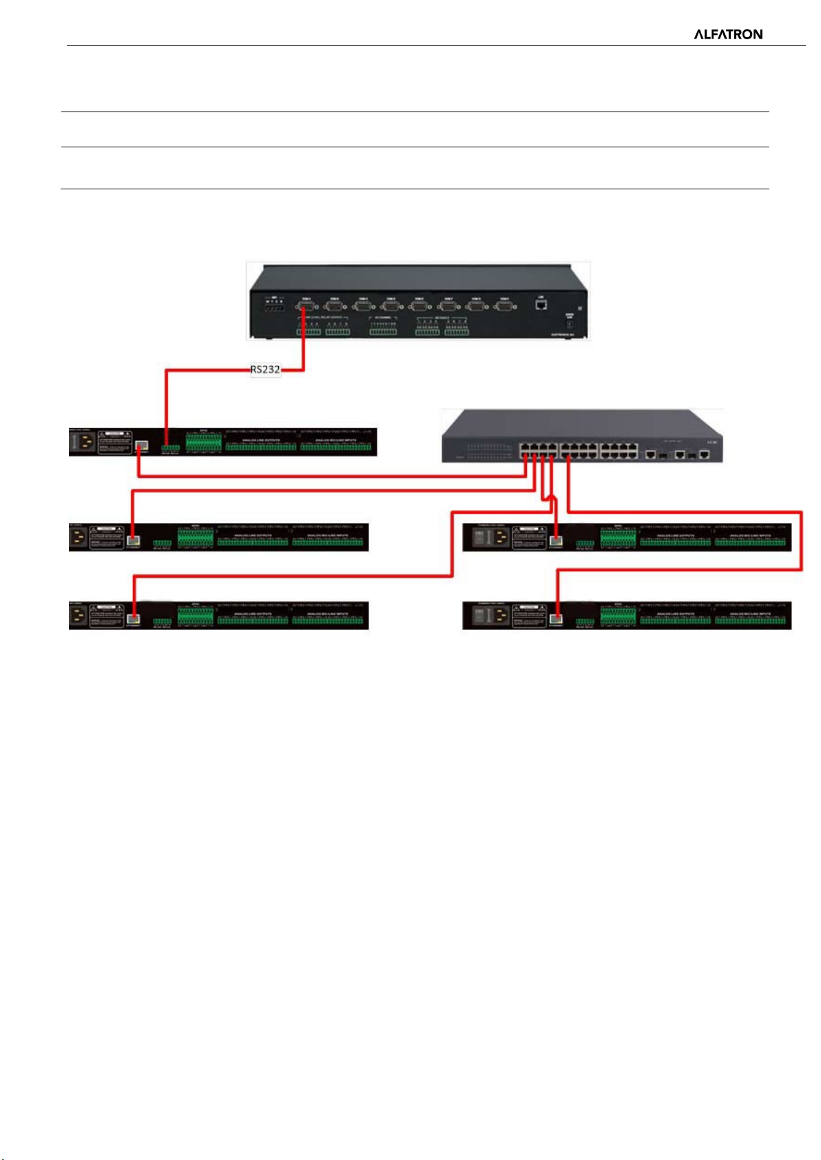
Application scenario: The function can be applied in scenarios when many central control hosts have no network port. As
shown in the below figure, central control hosts translate network commands through serial ports to control any network
device.
0x1610A8C0 0xC350 0x09 0x00 ”HELLO DSP”
5. FAQs
1. How to restore factory setting?
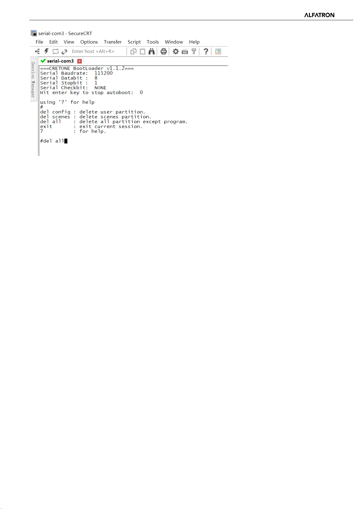
Connect the processor to a computer through RS232 and run the serial port software (SecureCRT is recommended for use).
The default baud rate of the serial port is 115200, 8 data bits, no parity check, and 1 stop bit. After connecting SecureCRT to
the serial port, long press to enter a terminal interface to reboot the computer and enter the bootloader boot dialog box as
shown in the below figure:
-41-
Page 42
ALF-DSP88-U
-42-
Page 43
ALF-DSP88-U
Command explanation:
del config: delete configuration information, such as network configurations like IP address. The device restores to default IP
169.254.20.227 after deleting.
del scenes: delete preset. All 16 presets of DSP devices restore to default values.
del all: delete all sections except the program.
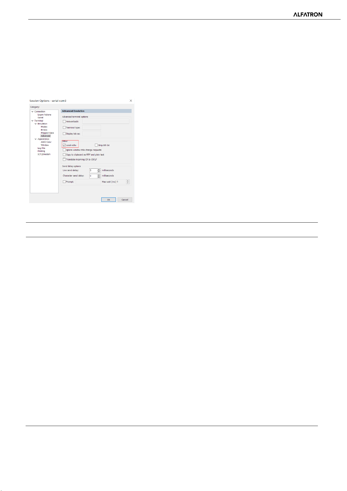
Note: There may be no echo after the installation of SecureCRT. Please check settings under “Local echo” by going to
Options->Session Options->Enable ‘Local Echo’, as shown in the picture below.
Appendix A: Module ID Distribution
Module Name ID Module Name ID
Input source 299 Output Channel 1-32 High &
Low Pass
Input Channel 1-32 Expander 1~32 Output Channel 1-32 Equalizer 199~230
Input Channel 1-32 Compressor 33~64 Output Channel 1-32 Delayer 231~262
Input Channel 1-32 Auto Gain 65~95 Output Channel 1-32 Limiter 263~294
Input Channel 1-32 Equalizer 97~128
Input Channel 1-32 Feedback
Inhibition
AutoMixer 161 Echo Canceller 162
Echo Cancellation 163 Noise Suppressor 164
129~160
167~198
Noise Suppression 165
Mixer 166
Output 295
System Control 296
-43-
Page 44

ALF-DSP88-U
Appendix B: Module Parameter Types (1)
Module
Name
Input
Source
Parameter
Type
0x1 Gain Output 0x10 Gain Compensation
0x2 Mute 0x11 Link
0x3 Sensitivity 0x12 Channel Level
0x4 Phantom Power Switch 0x1 Gain
0x5 Signal Generator Type 0x2 Mute
0x6
0x7 Sine Wave Gain Size 0x4 Invert
0x8 Channel Name 0x5 Sensitivity
0x9 Invert 0x6 Gain Compensation
0x10 Gain Compensation 0x7 Link
Description Module
Name
Signal Generator
Frequency
Parameter
Type
0x3 Channel Name
Description
0x11 Link 0x8 Channel Level
0x12 Channel Level Expander 0x1 Switch
Delayer 0x1 Bypass Switch 0x2 Threshold
0x2 Millisecond 0x3 Ratio
0x3 Microsecond 0x4 Setup Time
Equalizer 0x1 Total Equalizer Switch 0x5 Release Time
0x2 Child Segment Switch Compressor 0x1 Compressor Switch
0x3 Frequency 0x2 Compressor Threshold
0x4 Gain 0x3 Compressor Ratio
0x5 Q Value 0x4 Setup Time
0x6 Type 0x5 Recovery Time
0x6 Gain Compensation
-44-
Page 45

ALF-DSP88-U
Appendix B: Module Parameter Types (2)
Module
Name
Mixer 0x1 Mixer Switch Feedback
High & Low
Pass
Parameter
Type
0x2 Mixer Gain 0x2
0x1 High Pass Switch 0x3 Feedback Point Gain
0x2 High Pass Type 0x6 Preset
0x3 High Pass Slope 0x7 Clear
0x4 High Pass Frequency 0x8 Panic Threshold
0x5 High Pass Gain 0x9 Feedback
0x11 Low Pass Switch Auto Gain 0x1 Switch
0x12 Low Pass Type 0x2 Threshold
0x13 Low Pass Slope 0x3 Target Threshold
Description Module
Name
Inhibition
Parameter
Type
0x1 Switch
Feedback Point
Frequency
Description
0x14 Low Pass Frequency 0x4 Ratio
0x15 Low Pass Gain 0x5 Setup Time
Auto Mix 0x1 Total Mute 0x6 Release Time
0x2 Total Gain Echo
Cancellation
0x3 Slope 0x2 Echo Cancellation Mode
0x4 Response Time
0x5 Channel Auto Switch 0x2 Noise Suppression Mode
0x6 Channel Mute System
0x7 Channel Gain 0x2 System Gain
0x8 Priority
0x9 Auto Mix Switch
Noise
Suppression
Control
0x1 Echo Cancellation Switch
0x1 Noise Suppression Switch
0x1 System Mute
-45-
Page 46

ALF-DSP88-U
6. After-sales Service
Should you experience problems using the Alfatron ALF-DSP88-U, please note that any transport costs of the
equipment to the distributor are borne by the user during the warranty.
1) Product Limited Warranty: Alfatron warrants that its products will be free from defects in materials and
workmanship for seven years, which starts from the first day of purchase.
Proof of purchase in the form of a bill of sale or receipted invoice which is evidence that the unit is within the
warranty period must be presented to obtain warranty service.
2) What the warranty does not cover (servicing available for a fee):
● Warranty expiration.
● Factory applied serial number has been altered or removed from the product.
● Damage, deterioration, or malfunction caused by:
● Normal wear and tear.
● Use of supplies or parts not meeting product specifications.
● No certificate or invoice as the proof of warranty.
● The product model showed on the warranty card does not match with the product or if the product had
been altered.
● Damage caused by force majeure.
● Servicing not authorized by Alfatron.
● Any other causes which do not relate to a product defect.
● Delivery, installation or labour charges for installation or setup of the product.
3) Technical Support: Contact our after-sales department at
-46-
Page 47

ALF-DSP88-U
7. Warranty
1.1 This limited warranty covers defects in materials and workmanship in this product.
1.2 Should warranty service be required, proof of purchase must be presented to the Company. The
serial number on the product must be clearly visible and not have been tampered with in any way
whatsoever.
1.3 This limited warranty does not cover any damage, deterioration or malfunction resulting from any
alteration, modification, improper or unreasonable use or maintenance, misuse, abuse, accident,
neglect, exposure to excess moisture, fire, improper packing, and shipping (such claims must be
presented to the carrier), lightning, power surges, or other acts of nature. This limited warranty does
not cover any damage, deterioration or malfunction resulting from the installation or removal of this
product from any installation, any unauthorized tampering with this product, any repairs attempted
by anyone unauthorized by the Company to make such repairs, or any other cause which does not
relate directly to a defect in materials and/or workmanship of this product. This limited warranty
does not cover equipment enclosures, cables or accessories used in conjunction with this product.
This limited warranty does not cover the cost of normal maintenance. Failure of the product due to
insufficient or improper maintenance is not covered.
1.4 The Company does not warrant that the product covered hereby, including, without limitation, the
technology and/or integrated circuit(s) included in the product, will not become obsolete or that such
items are or will remain compatible with any other product or technology with which the product
may be used.
1.5 Only the original purchaser of this product is covered under this limited warranty. This limited
warranty is not transferable to subsequent purchasers or owners of this product.
1.6 Unless otherwise specified, the goods are warranted in accordance with the manufacturer’s product
specific warranties against any defect attributable to faulty workmanship or materials, fair wear and
tear being excluded.
1.7 This limited warranty only covers the cost of faulty goods and does not include the cost of labor and
travel to return the goods to the Company’s premises.
1.8 In the event of any improper maintenance, repair or service being carried out by any third persons
during the warranty period without the Company’s written authorization, the limited warranty shall
be void.
1.9 A 7 (seven) year limited warranty is given on the aforesaid product where used correctly according to
the Company’s instructions, and only with the use of the Company’s components.
-47-
Page 48

ALF-DSP88-U
1.10 The Company will, at its sole option, provide one of the following three remedies to whatever
extent it shall deem necessary to satisfy a proper claim under this limited warranty:
1.10.1 Elect to repair or facilitate the repair of any defective parts within a reasonable period of time,
free of any charge for the necessary parts and labor to complete the repair and restore this
product to its proper operating condition.; or
1.10.2 Replace this product with a direct replacement or with a similar product deemed by the
Company to perform substantially the same function as the original product; or
1.10.3 Issue a refund of the original purchase price less depreciation to be determined based on the
age of the product at the time remedy is sought under this limited warranty.
1.11 The Company is not obligated to provide the Customer with a substitute unit during the limited
warranty period or at any time thereafter.
1.12 If this product is returned to the Company this product must be insured during shipment, with
the insurance and shipping charges prepaid by the Customer. If this product is returned
uninsured, the Customer assumes all risks of loss or damage during shipment. The Company
will not be responsible for any costs related to the removal or reinstallation of this product
from or into any installation. The Company will not be responsible for any costs related to any
setting up this product, any adjustment of user controls or any programming required for a
specific installation of this product.
1.13 Please be aware that the Company’s products and components have not been tested with
competitor’s products and therefore the Company cannot warrant products and/or
components used in conjunction with competitor’s products.
1.14 The appropriateness of the goods for the purpose intended is only warranted to the extent
that the goods are used in accordance with the Company’s installation, classification, and
usage instructions.
1.15 Any claim by the Customer which is based on any defect in the quality or condition of the
goods or their failure to correspond with specification shall be notified in writing to the
Company within 7 days of delivery or (where the defect or failure was not apparent on
reasonable inspection by the Customer) within a reasonable time after discovery of the defect
or failure, but, in any event, within 6 months of delivery.
1.16 If delivery is not refused, and the Customer does not notify the Company accordingly, the
Customer may not reject the goods and the Company shall have no liability and the Customer
shall pay the price as if the goods had been delivered in accordance with the Agreement.
1.17 THE MAXIMUM LIABILITY OF THE COMPANY UNDER THIS LIMITED WARRANTY SHALL NOT
EXCEED THE ACTUAL PURCHASE PRICE PAID FOR THE PRODUCT.
-48-
 Loading...