

Page 1
www.alfatronelectronics.com
ALFATRON ELECTRONICS GmbH GERMANY
ALF-3XUSB2C and ALF-10XUSB2C
Full HD PTZ Camera
User Manual
Page 2
ALFATRON ALF-3XUSB2C
Attention
FCC Statement
Changes or modifications not expressly approved by the party responsible for compliance could void
the user's authority to operate the equipment.
This equipment has been tested and found to comply with the limits for a Class B digital device,
pursuant to Part 15 of the FCC Rules. These limits are designed to provide reasonable protection
against harmful interference in a residential installation. This equipment generates uses and can
radiate radio frequency energy and, if not installed and used in accordance with the instructions, may
cause harmful interference to radio communications.
However, there is no guarantee that interference will not occur in a particular installation. If this
equipment does cause harmful interference to radio or television reception, which can be determined
by turning the equipment off and on, the user is encouraged to try to correct the interference by one or
more of the following measures:
-- Reorient or relocate the receiving antenna.
-- Increase the separation between the equipment and receiver.
-- Connect the equipment into an outlet on a circuit different from that to which the receiver is
connected.
-- Consult the dealer or an experienced radio/TV technician for help
This device complies with part 15 of the FCC rules. Operation is subject to the following two
conditions (1) this device may not cause harmful interference, and (2) this device must accept any
interference received, including interference that may cause undesired operation and after
change.
1
Page 3

ALFATRON ALF-3XUSB2C
Please read this manual carefully before installation and use.
1. Precaution
1.1 Avoid damage to the camera caused by heavy pressure, strong vibration or immersion during
transportation, storage and installation.
1.2 Housing of this product is made of organic materials. Do not expose it to any liquid, gas or solids
which may corrode the shell.
1.3 Do not expose the product to rain or moisture.
1.4 To prevent the risk of electric shock, do not open the case. Installation and maintenance should only
be carried out by qualified technicians.
1.5 Do not use the product beyond the specified temperature, humidity or power supply specifications.
1.6 Wipe it with a soft, dry cloth when cleaning the camera lens. Wipe it gently with a mild detergent if
needed. Do not use strong or corrosive detergents to avoid scratching the lens and affecting the image;
1.7 This product contains no parts which can be maintained by users themselves. Any damage caused
by dismantling the product by user without permission is not covered by warranty.
2. Electrical Safety
Installation and use of this product must strictly comply with local electrical safety standards.
The power supply of the product is ±12V, the max electrical current is 2A.
3. Installation Safety
1.1 Do not rotate the camera head violently, otherwise it may cause mechanical failure.
1.2 This product should be placed on a stable desktop or other horizontal surface. Do not install the
product obliquely, otherwise it may display inclined image;
1.3 Ensure there are no obstacles within rotation range of the holder.
1.4 Do not power on before completely installation.
4. Magnetic Interference
Electromagnetic fields at specific frequencies may affect the video image. This product is Class A. It may
cause radio interference in household application. Appropriate measure is required.
2
Page 4

ALFATRON ALF-3XUSB2C
Content
1. CAMERA INSTAL L AT ION ....................................................................................................................... 4
1.1.CAMERA INTRODUCTION ...................................................................................................................... 4
1.2 POWER-ON INITIAL CONFIGURATION ..................................................................................................... 4
1.3 VIDEO OUTPUT .................................................................................................................................... 5
1.4 MOUNTING BRACKETS ......................................................................................................................... 5
2. PRODUCT OVERVIEW .......................................................................................................................... 7
2.1 DIMENSION ..................................................................................... ERROR! BOOKMARK NOT DEFINED.
2.1.3 Accessory .................................................................................................................................... 8
2.2 MAIN FEATURES .................................................................................................................................. 8
2.3 TECHNICAL PARAMETER ....................................................................................................................... 9
2.4 INTERFACE INSTRUCTION ................................................................................................................... 10
2.4.1 External Interface .......................................................................................................................11
2.4.2 RS-232 Interface ........................................................................................................................11
3. APPLICATION INSTRUCTION ............................................................................................................. 13
3.1 VIDEO OUTPUT .................................................................................................................................. 13
3.1.1 Power-On Initial Configuration .................................................................................................. 13
3.1.2 Video Output ............................................................................................................................. 13
3.2 REMOTE CONTROL ............................................................................................................................ 14
3.2.1 Keys Introduction ...................................................................................................................... 14
3.3 MENU INTRODUCTION ........................................................................................................................ 17
3.3.1 Main Menu ................................................................................................................................ 17
3.3.2 System Setting .......................................................................................................................... 18
3.3.3 Camera Setting ......................................................................................................................... 18
3.3.4 P/T/Z ......................................................................................................................................... 22
3.3.5 Version ...................................................................................................................................... 22
4. SERIAL PORT COMMUNICATION AND CONTROL ........................................................................... 24
4.1 VISCA PROTOCOL LIST ...................................................................................................................... 24
4.1.1 VISCA Protocol Return Command ........................................................................................... 24
4.1.2 VISCA Protocol Control Command ........................................................................................... 24
4.1.3 VISCA Protocol Inquiry Command ........................................................................................... 27
4.2 PELCO-D PROTOCOL COMMAND LIST ................................................................................................. 29
4.3 PELCO-P PROTOCOL COMMAND LIST ................................................................................................. 29
5. MAINTENANCE AND TROUBLESHOOTING ...................................................................................... 31
5.1 CAMERA MAINTENANCE ..................................................................................................................... 31
5.2 TROUBLESHOOTING ........................................................................................................................... 31
6. WARRANTY .......................................................................................................................................... 32
LIMITED WARRANTY IN RESPECT OF ALFATRON PRODUCTS......................................................... 32
3
Page 5
ALFATRON ALF-3XUSB2C
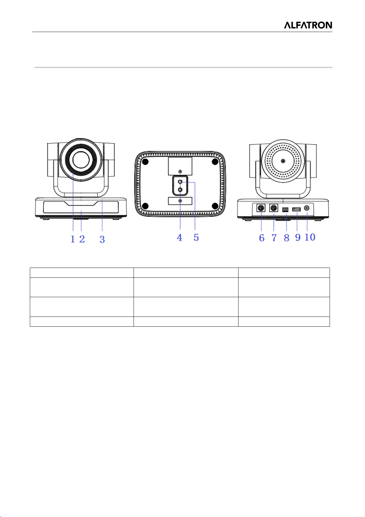
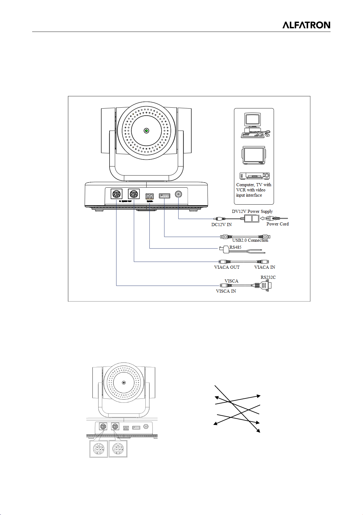
Indicator
(Input)
Supply Socket
(Output)
4. Tripod Screw Hole
8. RS485 Input (left +, right-)
1. Camera Installation
1.1. Camera Introduction
Figure 1.1 Product Interfaces
1. Camera Lens 5. Screw Hole for Tripod 9. USB 2.0 Interface
2.RemoteControl Receiving
3. Camera Base 7. RS232 Control Interface
6. RS232 Control Interface
10. DC12V Input Power
1.2 Power-on Initial Configuration
1) Power on: Connect DC12V power supply adapter with power supply socket
2) Initial Configuration: The remote-control receiving indicator flashes after it powers up, the pan-tilt
turns left to the lowest point and then turns to the HOME position (both the horizontal and vertical
positions are in the middle), the camera lens then moves backwards and forward. When remote
control receiving indicator stops flashing, the self-checking is complete.
Notes:
1) After powering up and self-checking, the camera will automatically return to the preset 0 position if
it is pre-set.
2) The default address for the IR remote control is 1. If the camera is restored to factory defaults, the
remote-control default address will also restore to 1.
4
Page 6
ALFATRON ALF-3XUSB2C
1.3 Video Output
USB2.0 Video Output
A. USB 2.0 video cable connection: as shown in Figure1.1 label 9
B. Connect the camera and the computer via USB2.0 video cable, open the video software and select
the device to output the video.
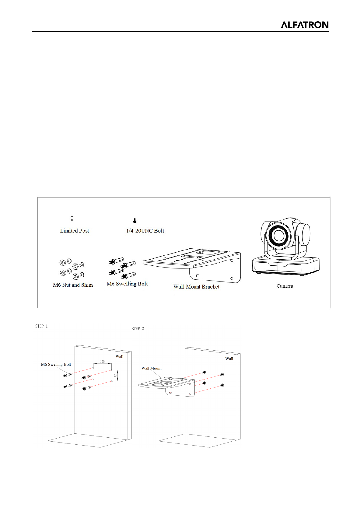
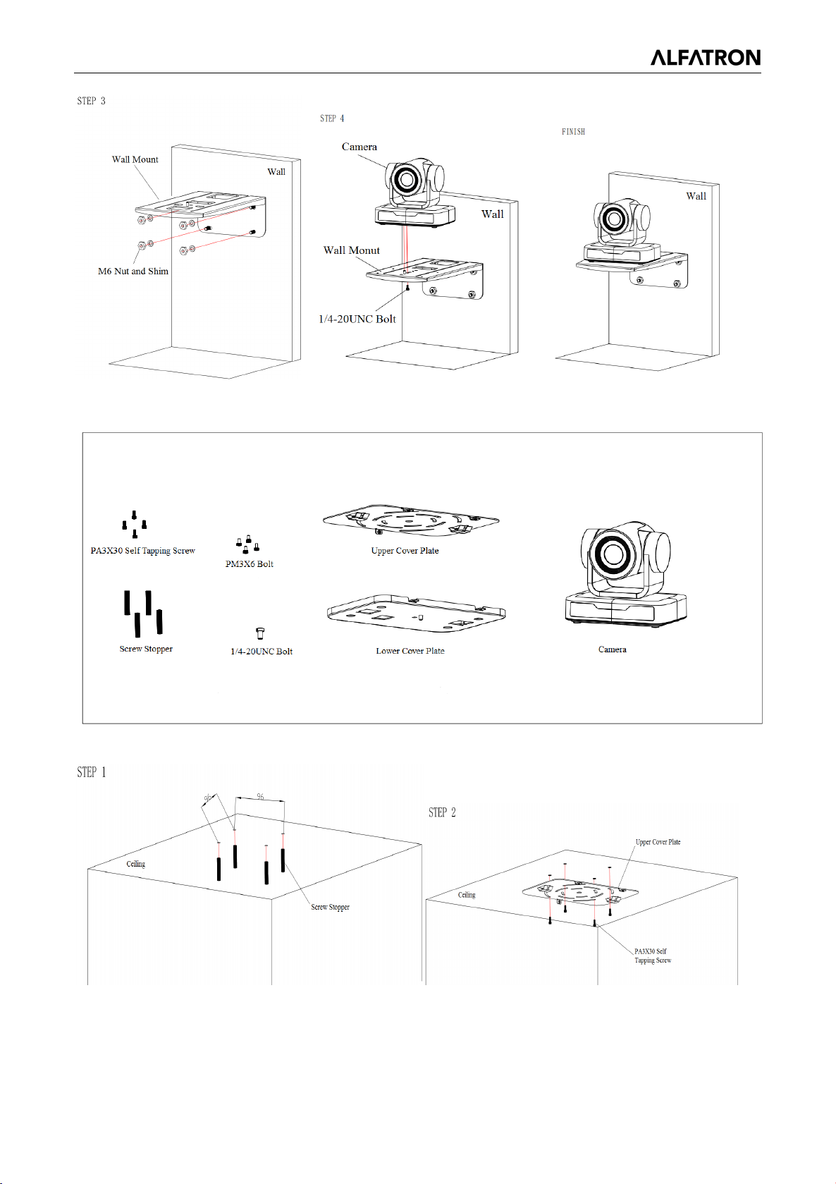
1.4 Mounting Brackets
Note: Ceiling or wall mounting brackets can only be mounted on template and concrete wall.
For safety reasons, plasterboard is not recommended.
1
)Wall Mounting:
5
Page 7
ALFATRON ALF-3XUSB2C
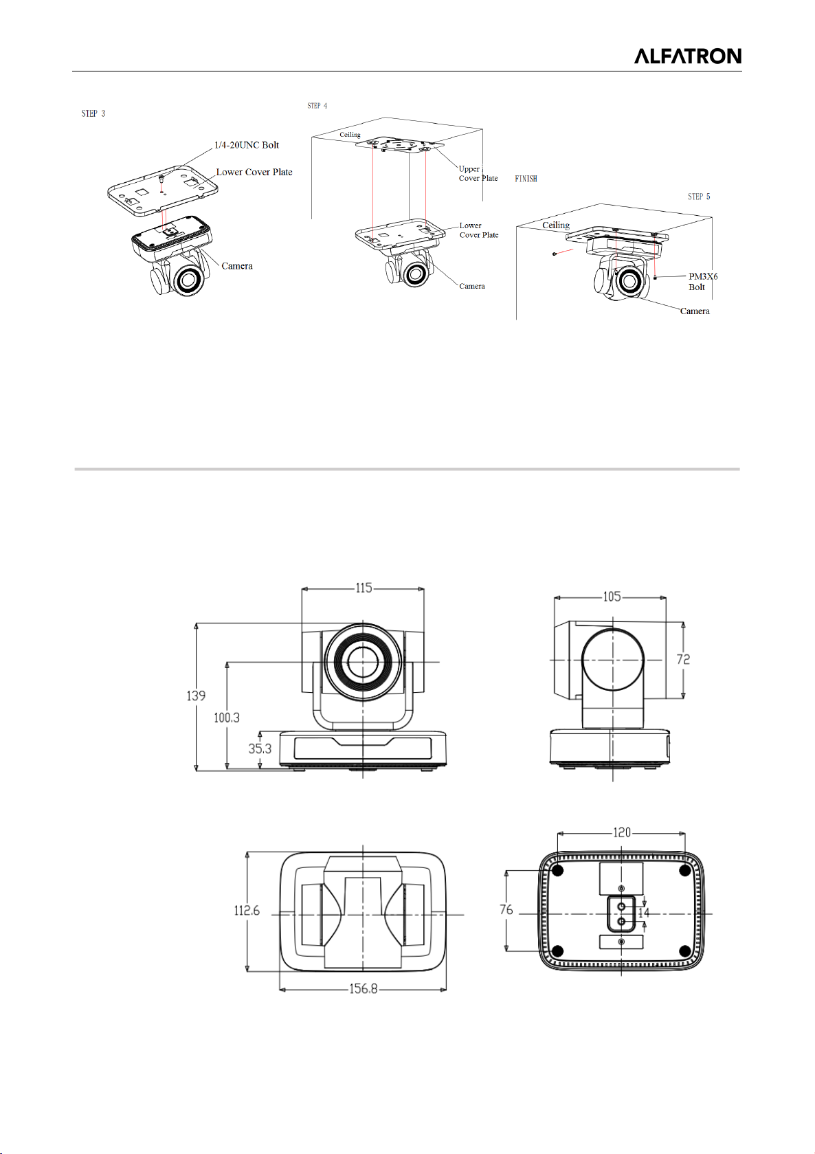
2)Ceiling Mounting
6
Page 8
ALFATRON ALF-3XUSB2C
2. Product Overview
2.1 Dimension
Figure 2.2 Product Dimension
7
Page 9

ALFATRON ALF-3XUSB2C
Standard Accessories
Accessories
Power adapter
Wall Mount or Ceiling Mount
USB2.0 Cable
2.1.3 Accessory
Please check below standard and optional accessories when unpacking the box.
IR Remote Control (One bracket included, specified on order)
RS232 Cable
User Manual
2.2 Main Features
This series camera has superior performance and rich video output interfaces. It has advanced ISP
processing algorithms, offering vivid and high-resolution video with a strong sense of depth and
exceptional color rendition.
Full HD Resolution: 1/2.9-inch-high quality CMOS sensor. Resolution is up to 1920x1080 with
frame rate up to 30 fps.
Multiple Optical Zoom Lens: 3X or 10X optical zoom lens.
Leading Auto Focus Technology: Fast, accurate and stable auto focusing technology.
Low Noise and High SNR: Super high SNR image is achieved with low noise CMOS. Advanced
2D/3D noise reduction technology further reduces the noise while ensuring high image clarity.
Control Interface: RS485, RS232 (cascade connection)
Multiple Control Protocol: Supports VISCA, PELCO-D, and PELCO-P protocols. Supports
automatic identification protocols.
Quiet Pan / Tilt Movement: With high accuracy step driven motor, camera can pan / tilt quietly and
smoothly.
Multiple presets: Up to 255 presets (10 presets via remote control).
Multiple Application: Online-education, Lecture Capture, Webcasting, Video conferencing,
Tele-medicine, Unified Communication, Emergency command and control systems, etc.
8
Page 10
ALFATRON ALF-3XUSB2C
Model
3X
10x
Camera Parameter
Sensor
1/2.9-inch-high quality CMOS sensor
Effective Pixels
2.07 megapixel, 16:9
H264/H265/MJPG:1920×1080P@30/25/20/15/10/5
320*180@30/25/20/15/10/5fps
View Angle
34.1° ~ 85°
8.8° ~ 66°
Focus Length
f=3.35mm ~ 10.05mm
F=4.34mm~41.66mm
AV
F1.7 ~ 3.0
F1.85 - F2.43
Optical Zoom
3X
10x
Digital Zoom
10X
Minimum
Illumination
0.5Lux (F1.8, AGC ON)
DNR
2D﹠3D DNR
White Balance
Auto / Manual/ One
00K/6500K/7000K
Focus
Auto / Manual/ One Push Focus
Exposure
Auto / Manual
BLC
On/Off
Brightness, Color, Saturation, Contrast, Sharpness,
B/W mode, Gamma curve
SNR
>50dB
Input/output Interface
Video Output
USB2.0 Interface
Video
Format
Control Interface
RS232 (IN/OUT), RS485
Control Protocol
VISCA/Pelco-D/Pelco-P
Power Interface
HEC3800 outlet (DC12V) or USB
USB Feature
Operation Systems
Windows 7, Windows8, Windows10, Mac osx, Linux, etc.
Video
Format
USB
Protocol
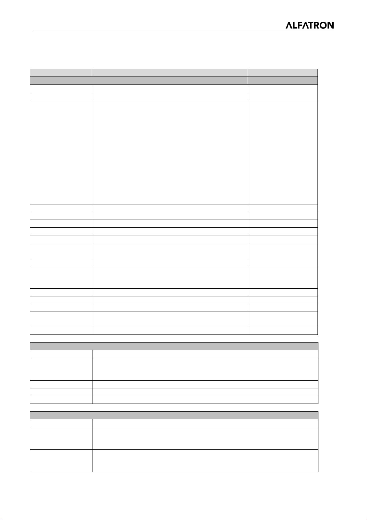
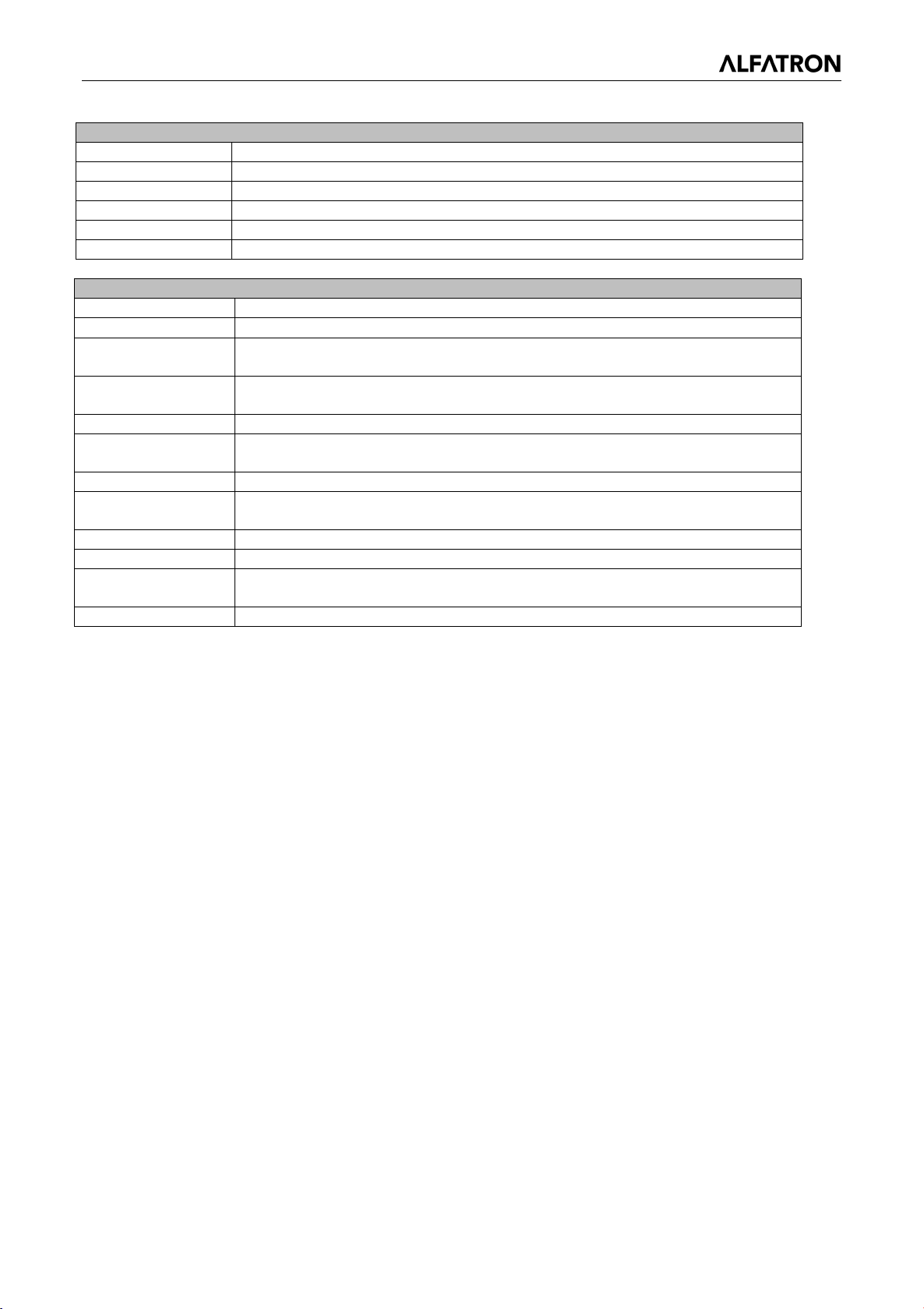
2.3 Technical Parameter
Video Format
fps;1280*720P@30/25/20/15/10/5fps;
960*540@30/25/20/15/10/5fps;
800*600@30/25/20/15/10/5fps;
720*576@30/25/20/15/10/5fps;
720*480@30/25/20/15/10/5fps;
640*480@30/25/20/15/10/5fps;
640*360@30/25/20/15/10/5fps;
352*288@30/25/20/15/10/5fps;
320*240@30/25/20/15/10/5fps;
YUY2:1280*720@10/5fps;800*600@10/5fps;
640*480@30/25/20/15/10/5fps;
640*360@30/25/20/15/10/5fps;
Push//3000K/3500K/4000K/4500K/5000K/5500K/60
Video Adjustment
Compression
Compression
Communication
MJPG, H.264, H.265
MJPG/H264/H265
UVC
9
Page 11
ALFATRON ALF-3XUSB2C
PTZ Parameter
Pan Rotation
-170°~+170°
Tilt Rotation
-30°~+30°
Pan Control Speed
0.1 ~60°/sec
Tilt Control Speed
0.1~40°/sec
Preset Speed
Pan: 60°/sec, Tilt: 40°/sec
Preset Number
255 presets (10 presets via remote control)
Other Parameter
Input Voltage
12V
Input Current
Maximum: 4.98A
Power
Consumption
Maximum: 2.5W
Stored
Temperature
-40℃~+70℃
Storage Humidity
20%~90%
Working
Temperature
-10℃~+50℃
Working Humidity
20%~80%
Dimension
(W*H*D)
156.8mm×112.6mm×139.5mm
Weight
1KG
Application
Indoor
Package
Power Supply, RS232 Control Cable, IR Remote Control, User Manual,
Warranty Card, USB2.0 Cable
Ceiling / Wall Mount
10
Page 12
ALFATRON ALF-3XUSB2C
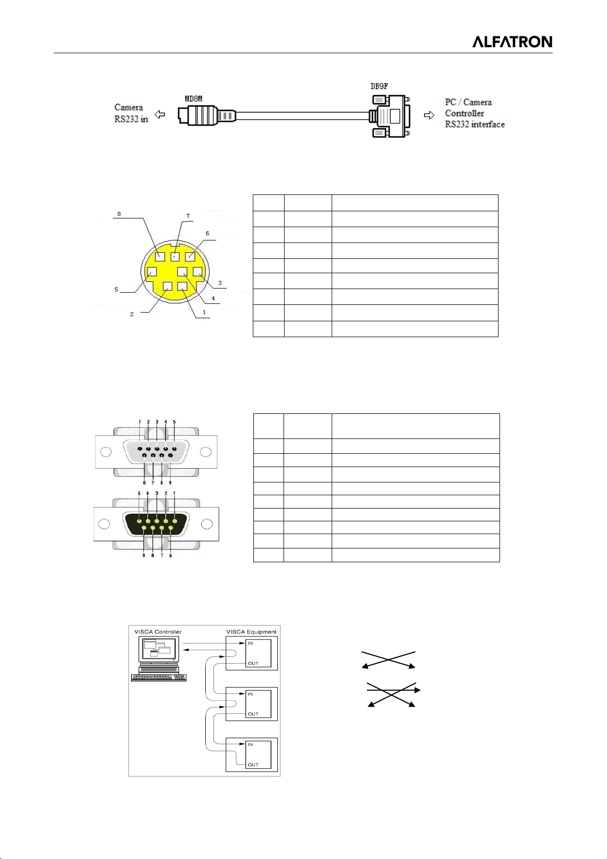
Connection to PC or Camera Controller
Camera
WindowsDB-9
1.DTR
3.TXD
3.TXD
4.GND
4.DTR
5.RXD
6.GND
6.DSR
7.IR OUT
7.RTS
8.NC
9.RI
2.4 Interface
2.4.1 External Interface
2.4.2 RS-232 Interface
1)RS-232 Interface Definition
Figure2.4 Wiring Diagram
2.DSR
1.DCD
2.RXD
5.GND
8.CTS
11
Page 13
ALFATRON ALF-3XUSB2C
Camera cascade connection
Camera 1
Camera 2
1.DTR
1.DTR
2.DSR
2.DSR
3.TXD
3.TXD
4.GND
4.GND
5.RXD
5.RXD
6.GND
6.GND
7.IR OUT
7.OPEN
8. NC
8.OPEN
NO.
Port
Definition
1
DTR
Data Terminal Ready
2
DSR
Data Set Ready
3
TXD
Transmit Data
4
GND
Signal Ground
5
RXD
Receive Data
6
GND
Signal Ground
7
IR OUT
IR Commander Signal
8
NC
No Connection
NO
.
Definition
1
DCD
Data Carrier Detect
2
RXD
Receive Data
3
TXD
Transmit Data
4
DTR
Data Terminal Ready
5
GND
System Ground
6
DSR
Data Set Ready
7
RTS
Request to Send
8
CTS
Clear to Send
9
RI
Ring Indicator
2)RS-232 Mini-DIN 8-pin Port Definition
3)RS232(DB9) Port Definition
Port
4)VISCA networking as shown below
12
Page 14

ALFATRON ALF-3XUSB2C
3. Application Instruction
3.1 Video Output
3.1.1 Power-On Initial Configuration
Initial Configuration: The remote-control receiving indicator flashes after it powers up, the pan-tilt turns
left to the lowest point and then turns to the HOME position (both the horizontal and vertical positions
are in the middle), the camera lens then moves backwards and forward. When remote control
receiving indicator stops flashing, the self-checking is complete.
3.1.2 Video Output
Connect to the video output cable: the user can refer to Figure 1.1 product interfaces.
USB 2.0 output: Connect the camera with the computer USB2.0 interface (black), open the Device
Manager to see whether there is an imaging device and whether the Universal Serial Bus controllers
recognize the USB 2.0 device. After properly identified, open the software, choose the device, and then it
will output the image.
13
Page 15
ALFATRON ALF-3XUSB2C
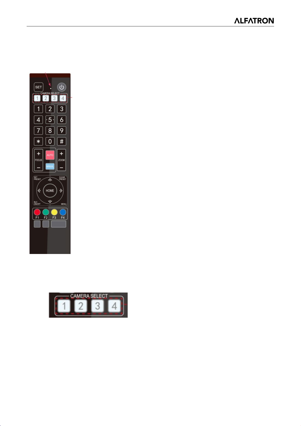
3.2 Remote Control
3.2.1 Keys Introduction
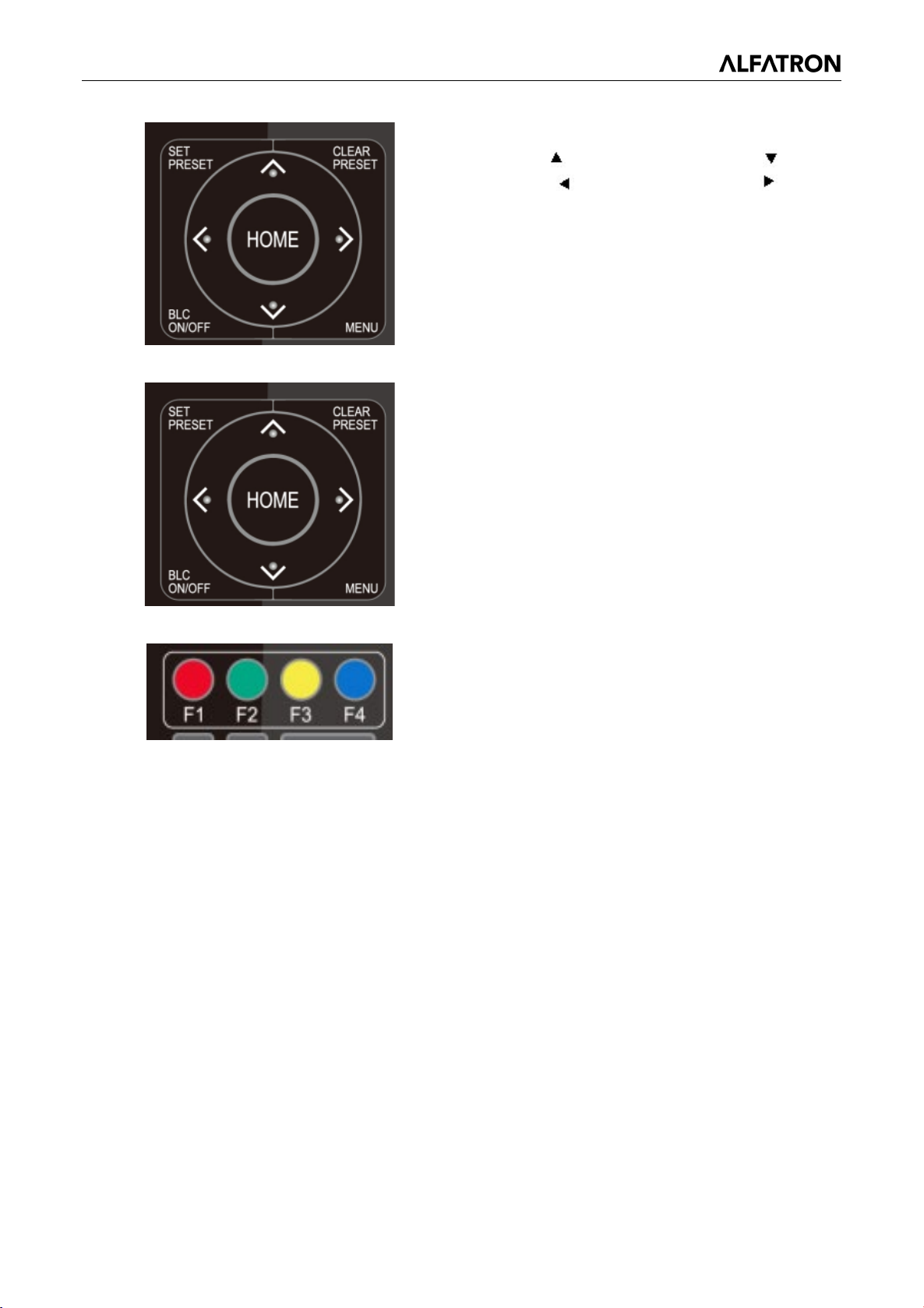
1) In this manual, “press the key” means a click rather than a long-press, and a
special note will be given if a long-press for more than one second is required.
2) When a key-combination is required, do it in sequence. For example, “【*】+
【#】+【F1】” means press “【*】” first and then press “【#】” and last press “【F1】”.
1. Standby Key
The camera will enter standby mode if you long press (3s) on the standby key;
Long press (3s) again on the standby key, the camera will do self-check and
return to the HOME position (If preset 0 position is set, the camera will return to
preset 0 position).
2. Camera Selection
Select the camera address to control.
14
Page 16
ALFATRON ALF-3XUSB2C
9 to set preset
【#】
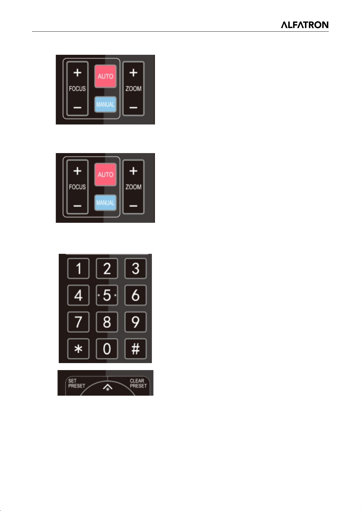
3. Focus Control
Auto: Auto focus mode
Manual: Manual focus mode
Focus + (near): Press【FOCUS +】 key (Valid only
in manual focus mode)
Focus - (far): Press【FOCUS -】 key (Valid only in
manual focus mode)
Press and hold the keys, the focus action will
4. Zoom Control
continue and stop as soon as the key is released.
ZOOM +: press【ZOOM +】key to zoom in
ZOOM -: press 【ZOOM -】key to zoom out
Press and hold the keys, the focus action will
continue and stop as soon as the key is released.
5. Set and Clear Presets
Set Preset: press 【SET PRESET】
then press the number key 0-
positions.
Note: 10 presets via remote control.
Call Preset: Press a number key 0-9 directly to call
a preset position.
Clear Preset: press 【CLEAR PRESET】 button,
and then press the number key 0-9 to clear preset
positions.
Note: press the
to clear all presets.
key three times continually
button, and
15
Page 17
ALFATRON ALF-3XUSB2C
【
【
ens back to the middle
【
*】+
:Camera Address No. 4
6. Pan/Tilt Control
Up: press Down: press
Left: press
Back to middle position: press “【HOME】”
Press and hold the up/down/left/right key, the
pan/tilt movements will continue moving, from slow
to fast, until it runs to the endpoint; it will stop as
soon as the key is released.
7. Menu Setting
MENU】: Open / close the OSD menu
HOME】: Camera l
position; Confirm button; Enter next menu
【↑】【 ↓】: Choose item
【←】【 →】: Modify values
BLC ON/OFF】:Turn on or off the back light
compensation
Right: press
8. Camera Remote Control Address Setting
【*】+【#】+【F1】:Camera Address No.1
【*】+【#】+【F2】:Camera Address No. 2
【*】+【#】+【F3】:Camera Address No. 3
【
【#】+【F4】
16
Page 18

ALFATRON ALF-3XUSB2C
Setup: System parameter setting
MENU
================
(
)
(
)
(
)
(
)
(
↑↓
3.3 Menu Introduction
3.3.1 Main Menu
In normal working mode, press 【MENU】 key to display the menu, using scroll arrow to point at or
highlight the selected items.
Setup
Camera
P/T/Z
Version
Restore Default)
[
] Select [← →] Change Va l ue
[Menu]Back [Home]OK
Camera: Camera parameter setting
P/T/Z: Enter sub menu
Version: Enter sub menu
Restore Default: Enter reset setting, select YES or NO to confirm
[↑↓] Select: For selecting menu
[← →] Change Value: For modifying parameters
[MENU] Back: Press [Menu] to return
[Home] OK: Press [Home] to confirm
17
Page 19

ALFATRON ALF-3XUSB2C
Protocol: VISCA / Pelco-P / Pelco-D / Auto
Visca Address: VISCA=1~7 Pelco-P=1~255 Pelco-D=1~255
Baudrate: 2400/4800/9600/115200
Visca Address Fix: On/Off
Auto Filp: On/Off
=================
(
)
(
)
(
(
(
)
↑↓
[← →
[Menu]Back [Home]OK
================
1
[↑↓]Select [← →]Change Value
3.3.2 System Setting
Move the pointer to the (Setup) in the Main Menu, click the【HOME】key and enter the (System Setting)
as shown below:
SETUP
Protocol
Visca Address
Visca Address Fix
PELCO-P Address
PELCO-D Address 1
Baudrate
Auto Filp ON
Auto
OFF
9600
1
3.3.3 Camera Setting
Move the pointer to the (CAMERA) in the Main Menu, click the 【HOME】key and enter the (CAMERA) as
follows:
CAMERA
Exposure
Color
Image)
Focus)
Noise Reduction
Style Default
[
]Select
Exposure: Enter Exposure setting
Color: Enter color setting
Image: Enter image setting
Focus: Enter focus setting
Noise Reduction: Enter noise reduction
]Change Value
18
Page 20

ALFATRON ALF-3XUSB2C
Mode: Auto, Manual, Shutter priority, Iris priority and Brightness priority.
EV: On/Off (only available in auto mode)
Compensation Level: -7~7 (only available in auto mode when EV is ON)
BLC: ON/OFF for options (only available in auto mode)
Dynamic Range: 1~8, close
Anti-Flicker: OFF/50Hz/60Hz for options (only available in Auto/Iris priority/Brightness priority modes)
Gain limit: 0~15 (only available in Auto/ Iris priority /Brightness priority mode)
WDR: Off, 1~8
ShutterPriority:1/25,1/30,1/50,1/60,1/90,1/100,1/120,1/180,1/250,1/350,1/500,1/1000,1/2000,1/3000,1/
4000,1/6000, 1/10000 (only available in Manual and Shutter priority mode)
IRIS Priority: OFF, F11.0, F9.6, F8.0, F6.8, F5.6, F4.8, F4.0, F3.4, F2.8, F2.4, F2.0, F1.8 (only available
in Manual and Iris priority mode)
Brightness: 0~23 (only available in Brightness priority mode)
EXPOSURE
=================
[↑↓
[← →
[Menu]Back
1)Exposure Setting
Move the pointer to the (EXPOSURE) in the Main Menu, click the【HOME】key and enter the (Exposure
sub menu) as shown below:
Mode
EV
BLC
Flicker 50Hz
G.Limit 3
DRC 2
]Select
Auto
OFF
OFF
]Change Value
19
Page 21

ALFATRON ALF-3XUSB2C
60%,70%,80%,90%,100%,110%,120%,130%,140%,150%,160%,170%,180%,190%,200%
Red fine-tuning: -10~10 (only available in automatic mode)
Blue fine-tunable: -10~10 (only available in automatic mode)
RED GAIN: 0~255(only available in Manual mode)
================
↑↓
COLOR
================
↑↓
[Menu]Back
2)Color
Move the pointer to the (COLOR) in the Main Menu, click the【HOME】key and enter the (COLOR sub
menu) as follows:
WB Mode
RG Tuning -10
BG Tuning
Saturation
Hue 7
AWB Sensitivity High
[
]Select [← →]Change Value
-10
Auto
100%
WB Mode: Auto, Manual, One Push, 3000K, 3500K, 4000K, 4500K, 5000K, 5500K, 6000K,
6500K,7000K
Saturation:
BLUE GAIN: 0~255(only available in Manual mode)
AWB Sensitivity: high/middle/low
Chroma: 0~14
3) Image
Move the pointer to the (IMAGE) in the Menu, click the【HOME】key and enter the (IMAGE sub menu) as
follows:
IMAGE
Brightness
Contrast
Sharpness
Flip-H OFF
Flip-V
B&W-Mode Color
Gamma Default
DCI Close
Low-Light Mode OFF
[
7
8
3
OFF
]Select [← →]Change Value
20
Page 22

ALFATRON ALF-3XUSB2C
NOISE REDUCTION
=================
↑↓
[Menu]Back
FOCUS
=================
↑↓
Brightness: 0~14
Contrast: 0~14
Sharpness: 0~15
Flip-H: On/Off
Flip-V: On/Off
B&W Mode: color, black/white
Gamma: Default/0.45/0.50/0.5/0.63
DCI: Dynamic Contrast: Off/1~8
Minimum Illumination: On/Off
4)Focus
Move the pointer to the (FOCUS) in the Menu, click the【HOME】key and enter the (FOCUS) as follows:
Focus Mode Auto
AF-Zone All
AF-Sensitivity Low
[
]Select
[Menu]Back
[← →]Change Value
Focus Mode: Auto/manual
AF-Zone: Up/middle/down
AF-Sensitivity: High/middle/low
5)Noise Reduction
Move the pointer to the (NOISE REDUCTION) in the Menu, click the【HOME】key and enter the (NOISE
REDUCTION) as follows:
2D Noise Reduction: Auto, close, 1~7
3D Noise Reduction: Close, 1~8
Dynamic Hot Pixel: Close, 1~5
NR-2D 4
NR-3D 2
Dynamic Hot Pixel OFF
[
]Select
[← →]Change Value
21
Page 23

ALFATRON ALF-3XUSB2C
================
↑↓
=================
↑↓
3.3.4 P/T/Z
Move the pointer to the (P/T/Z) in the Main Menu, click the【HOME】key and enter the (P/T/Z) as follows:
P/T/Z
Speed by zoom ON
Zoom speed
Acc Curve Slow
[
]Select [← →]Change Value
[Menu]Back
Depth of Field: Only effective for the remote controller, On/ Off;
(When zooming in, the PT control speed by remote controller will become slow)
Zoom Speed: Set the zoom speed for the remote controller, 1~8
Image Freezing: On/Off
Accelerating Curve: Fast/Slow
8
3.3.5 Version
Move the pointer to the (VERSION) in the Main Menu, click the【HOME】key and enter the (VERSION) as
follows:
VERSION
MCU Version 3.1.0 2019-09-26
Camera Version 1.0.5 2019-09-27
AF Version 1.0.0 2019-09-07
[
]Select
[Menu]Back
MCU Version: Display MCU version information
Camera Version: Display camera version information
AF Version: Display the focus version information
[← →]Change Value
[Home]OK
22
Page 24

ALFATRON ALF-3XUSB2C
RESTORE DEFAULT
=================
↑↓
3.3.6 Restore Default
Move the pointer to the (RESTORE DEFAULT) in the Main Menu, click the【HOME】key and enter the
(RESTORE DEFAULT) as follows:
Restore Default? NO
[
]Select
[Menu]Back
[← →]Change Value
[Home]OK
Restore default: YES/NO. Color style and video format cannot be restored to factory default
Note: If the address of former remote controller is not 1 but another one from 2, 3, 4, the
corresponding camera address will restore to 1 when all parameters or system parameters are
restored. User should change the remote controller address to be 1 (press No.1 according to the
camera to get normal operation).
23
Page 25
ALFATRON ALF-3XUSB2C
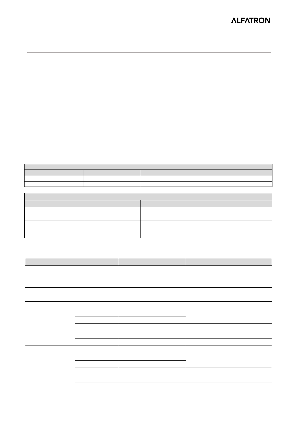
Ack/Completion Message
Command packet
Note
ACK
z0 41 FF
Returned when the command is accepted.
Completion
z0 51 FF
Returned when the command has been executed.
Error Messages
Command packet
Note
manually are received during auto focus.
Command
Function
Command packet
Note
CommandCancel
8x 21 FF
Off
8x 01 04 00 03 FF
Tele (Standard)
8x 01 04 07 02 FF
Wide (Variable)
8x 01 04 07 3p FF
Far (Standard)
8x 01 04 08 02 FF
4. Serial Port Communication and Control
The camera could be controlled through RS232/RS485 interface. RS232C serial parameters are as
follows:
Baud rate: 2400/4800/9600/115200 bits / sec; Start bit: 1; data bits: 8; Stop bit: 1; Parity: None.
Initial Configuration: The remote-control receiving indicator flashes after it powers up, the pan-tilt turns
left to the lowest point and then turns to the HOME position (both the horizontal and vertical positions are
in the middle), the camera lens then moves backwards and forward. When remote control receiving
indicator stops flashing, the self-checking is complete.
4.1 VISCA Protocol list
4.1.1 VISCA Protocol Return Command
z = camera address + 8
Syntax Error z0 60 02 FF
Command Not Executable z0 61 41 FF
Returned when the command format is different or when a
command with illegal command parameters is accepted
Returned when a command cannot be executed due to current
conditions. For example, when commands controlling the focus
4.1.2 VISCA Protocol Control Command
AddressSet Broadcast 88 30 0p FF
IF_Clear Broadcast 88 01 00 01 FF I/F Clear
CAM_Power
CAM_Zoom
On 8x 01 04 00 02 FF
Stop 8x 01 04 07 00 FF
Wide (Standard) 8x 01 04 07 03 FF
Tele (Variable) 8x 01 04 07 2p FF
p:Address setting
Power ON/OFF
p = 0(low) - F(high)
Direct 8x 01 04 47 0p 0q 0r 0s FF pqrs: Zoom Position
Stop 8x 01 04 08 00 FF
CAM _Focus
Near (Standard) 8x 01 04 08 03 FF
Far (Variable) 8x 01 04 08 2p FF
Near (Variable) 8x 01 04 08 3p FF
p = 0(low) - F(high)
24
Page 26
ALFATRON ALF-3XUSB2C
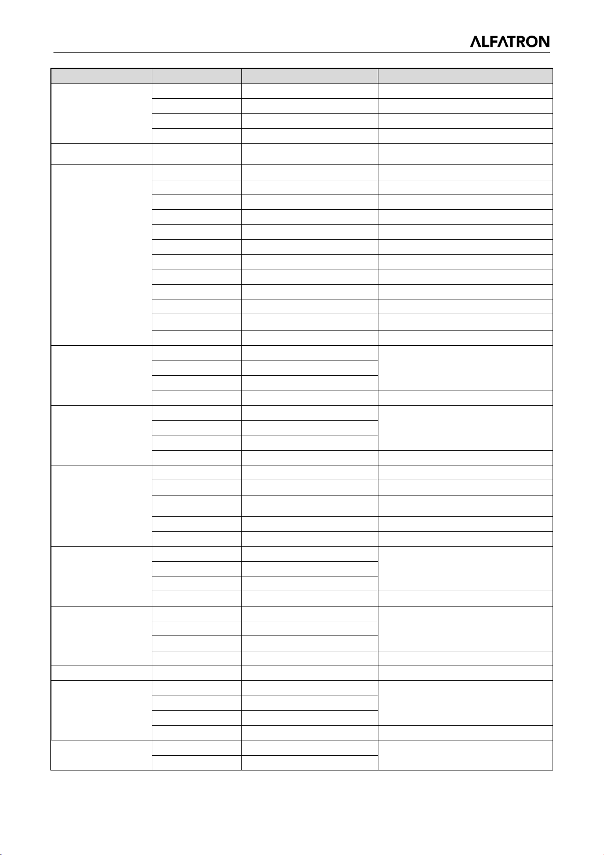
Command
Function
Command packet
Note
Auto Focus
8x 01 04 38 02 FF
One Push mode
8x 01 04 47 0p 0q 0r 0s
0t 0u 0v 0w FF
pqrs: Zoom Position
tuvw: Focus Position
Auto
One Push mode
Manual
5500K
8x 01 04 35 09 FF
7000K
8x 01 04 35 0B FF
Full Auto
8x 01 04 39 00 FF
Automatic Exposure mode
Shutter Priority Automatic Exposure
mode
CAM_Gain Limit
Gain Limit
8x 01 04 2C 0p FF
p: Gain Positon
Down
8x 01 04 0D 03 FF
On
8x 01 04 3E 02 FF
Direct 8x 01 04 48 0p 0q 0r 0s FF pqrs: Focus Position
Manual Focus 8x 01 04 38 03 FF
8x 01 04 38 04 FF
CAM _Zoom Focus Direct
CAM_WB
CAM _RGain
CAM_ Bgain
3000K 8x 01 04 35 01 FF
4000k 8x 01 04 35 02 FF
5000k 8x 01 04 35 04 FF
6500k 8x 01 04 35 06 FF
3500K 8x 01 04 35 07 FF
4500K 8x 01 04 35 08 FF
6000K 8x 01 04 35 0A FF
Reset 8x 01 04 03 00 FF
Up 8x 01 04 03 02 FF
Down 8x 01 04 03 03 FF
Direct 8x 01 04 43 00 00 0p 0q FF pq: R Gain
Reset 8x 01 04 04 00 FF
Up 8x 01 04 04 02 FF
Down 8x 01 04 04 03 FF
Direct 8x 01 04 44 00 00 0p 0q FF pq: B Gain
8x 01 04 35 00 FF
8x 01 04 35 03 FF
8x 01 04 35 05 FF
Manual Control of R Gain
Manual Control of B Gain
CAM_AE
CAM_Shutter
CAM_Iris
CAM_Bright
CAM_ExpComp
Manual 8x 01 04 39 03 FF Manual Control mode
Shutter priority 8x 01 04 39 0A FF
Iris priority 8x 01 04 39 0B FF Iris Priority Automatic Exposure mode
Bright 8x 01 04 39 0D FF Bright mode
Reset 8x 01 04 0A 00 FF
Up 8x 01 04 0A 02 FF
Down 8x 01 04 0A 03 FF
Direct 8x 01 04 4A 00 00 0p 0q FF pq: Shutter Position
Reset 8x 01 04 0B 00 FF
Up 8x 01 04 0B 02 FF
Down 8x 01 04 0B 03 FF
Direct 8x 01 04 4B 00 00 0p 0q FF pq: Iris Position
Reset 8x 01 04 0D 00 FF
Up 8x 01 04 0D 02 FF
Direct 8x 01 04 4D 00 00 0p 0q FF pq: Bright Positon
Off 8x 01 04 3E 03 FF
Shutter Setting
Iris Setting
Bright Setting
Exposure Compensation ON/OFF
25
Page 27
ALFATRON ALF-3XUSB2C
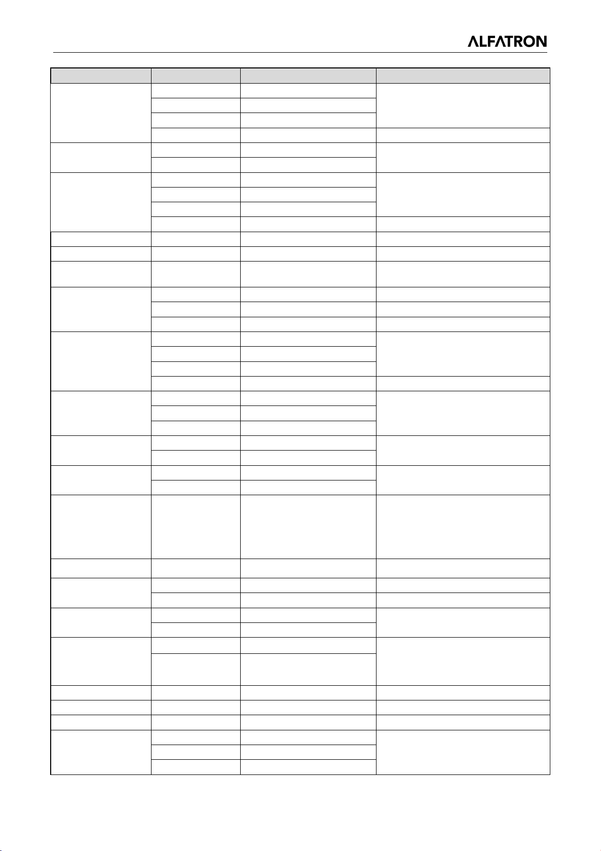
Command
Function
Command packet
Note
Up
8x 01 04 0E 02 FF
Up
8x 01 04 21 02 FF
0.45
0.50
3
0.55 4:0.63
Off
8x 01 04 66 03 FF
P=0-E
14:200%
CAM_Brightness
Direct
8x 01 04 A1 00 00 0p 0q FF
pq: Brightness Position
Reset 8x 01 04 0E 00 FF
Down 8x 01 04 0E 03 FF
Direct 8x 01 04 4E 00 00 0p 0q FF pq: ExpComp Position
CAM_Back Light
CAM_WDRStrength
CAM_NR(2D)
CAM_NR(3D)
CAM_Gamma 8x 01 04 5B 0p FF
CAM_Flicker
CAM_Aperture
CAM_Memory
CAM_LR_Reverse
CAM_PictureFlip
On 8x 01 04 33 02 FF
Off 8x 01 04 33 03 FF
Reset 8x 01 04 21 00 FF
Down 8x 01 04 21 03 FF
Direct 8x 01 04 51 00 00 00 0p FF p: WDR Level Positon
8x 01 04 53 0p FF P=0-7 0: OFF
8x 01 04 54 0p FF P=0-8 0: OFF
OFF 8x 01 04 23 00 FF OFF
50HZ 8x 01 04 23 01 FF 50HZ
60HZ 8x 01 04 23 02 FF 60HZ
Reset 8x 01 04 02 00 FF
Up 8x 01 04 02 02 FF
Down 8x 01 04 02 03 FF
Direct 8x 01 04 42 00 00 0p 0q FF pq: Aperture Gain
Reset 8x 01 04 3F 00 pq FF
Set 8x 01 04 3F 01 pq FF
Recall 8x 01 04 3F 02 pq FF
On 8x 01 04 61 02 FF
Off 8x 01 04 61 03 FF
On 8x 01 04 66 02 FF
Exposure Compensation Amount
Setting
Back Light
Compensation
WDR Level Setting
p = 0 – 4 0:Default 1:
:
Aperture Control
pq: Memory Number (=0 to 254)
Corresponds to 0 to 9 on the Remote
Commander
Image Flip Horizontal ON/OFF
Image Flip Vertical ON/OFF
2:
0:60% 1:70% 2:80% 3:90% 4:100%
CAM_ColorSaturation Direct 8x 01 04 49 00 00 00 0p FF
CAM_IDWrite 8x 01 04 22 0p 0q 0r 0s FF pqrs: Camera ID (=0000 to FFFF)
SYS_Menu
IR_Receive
IR_ReceiveReturn
CAM_SettingReset Reset 8x 01 04 A0 10 FF Reset Factory Setting
CAM_Contrast Direct 8x 01 04 A2 00 00 0p 0q FF pq: Contrast Position
CAM_Flip
ON 8x 01 04 06 06 02 FF Turn on the menu screen
OFF 8x 01 04 06 06 03 FF Turn off the menu screen
ON 8x 01 06 08 02 FF
OFF 8x 01 06 08 03 FF
On 8x 01 7D 01 03 00 00 FF IR (remote commander) receive
Off 8x 01 7D 01 13 00 00 FF
OFF 8x 01 04 A4 00 FF
Flip-V
8x 01 04 A4 02 FF
5:110% 6:120% 7:130%
8:140% 9:150% 10:160%
11:160% 12:180% 13:190%
IR (remote commander) receive on/Off
message via the VISCA communication
ON/OFF
Single Command for Video Flip Flip-H 8x 01 04 A4 01 FF
26
Page 28
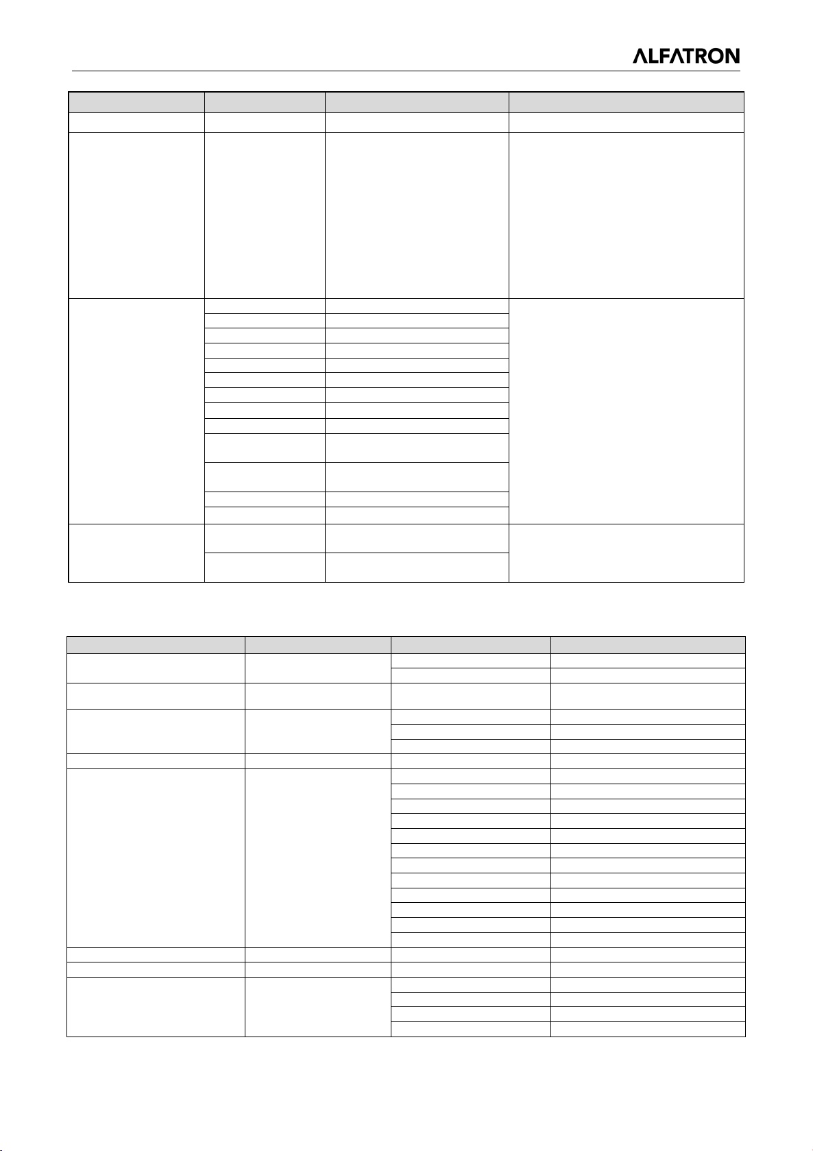
ALFATRON ALF-3XUSB2C
Command
Function
Command packet
Note
P: 0~E Video format
7:1080P25
Up
8x 01 06 01 VV WW 03 01 FF
Down
8x 01 06 01 VV WW 03 02 FF
Left
8x 01 06 01 VV WW 01 03 FF
Right
8x 01 06 01 VV WW 02 03 FF
Upleft
8x 01 06 01 VV WW 01 01 FF
Upright
8x 01 06 01 VV WW 02 01 FF
DownLeft
8x 01 06 01 VV WW 01 02 FF
DownRight
8x 01 06 01 VV WW 02 02 FF
Stop
8x 01 06 01 VV WW 03 03 FF
8x 01 06 02 VV WW
0Y 0Y 0Y 0Y 0Z 0Z 0Z 0Z FF
8x 01 06 03 VV WW
0Y 0Y 0Y 0Y 0Z 0Z 0Z 0Z FF
Home
8x 01 06 04 FF
Reset
8x 01 06 05 FF
8x 01 06 07 00 0W
0Y 0Y 0Y 0Y 0Z 0Z 0Z 0Z FF
8x 01 06 07 01 0W
07 0F 0F 0F 07 0F 0F 0F FF
Command
Command Packet
Return Packet
Note
y0 50 02 FF
On
y0 50 03 FF
Off(Standby)
y0 50 02 FF
Auto Focus
y0 50 03 FF
Manual Focus
y0 50 04 FF
One Push mode
CAM_FocusPosInq
8x 09 04 48 FF
y0 50 0p 0q 0r 0s FF
pqrs: Focus Position
y0 50 00 FF
Auto
y0 50 01 FF
3000K
y0 50 02 FF
4000K
y0 50 03 FF
One Push Mode
y0 50 04 FF
5000K
y0 50 05 FF
Manual
y0 50 00 FF
6500K
y0 50 06 FF
6500K
y0 50 07 FF
3500K
y0 50 08 FF
4500K
y0 50 09 FF
5500K
y0 50 0A FF
6000K
CAM_RGainInq
8x 09 04 43 FF
y0 50 0B FF
7000K
CAM_BGainInq
8x 09 04 44 FF
y0 50 00 00 0p 0q FF
pq: B Gain
y0 50 00 FF
Full Auto
y0 50 03 FF
Manual
y0 50 0A FF
Shutter priority
y0 50 0B FF
Iris priority
CAM_VideoSystem
Pan_tiltDrive
Flip-HV
Set camera video
system
AbsolutePosition
RelativePosition
8x 01 04 A4 03 FF
8x 01 06 35 00 0p FF
0:1080P60 8:720P30
1:1080P50 9:720P25
2:1080i60 A:
1080P59.94
3:1080i50 B:1080i59.94
4:720P60 C:720P59.94
5:720P50 D:
1080P29.97
6:1080P30 E:720P29.97
VV: Pan speed 0x01 (low speed) to
0x18 (high speed)
WW: Tilt speed 0x01 (low speed) to
0x14 (high speed)
YYYY: Pan Position
ZZZZ: Tilt Position
Set
Pan-tiltLimitSet
Clear
W:1 UpRight 0: DownLeft
YYYY: Pan Limit Position (TBD)
ZZZZ: Tilt Limit Position (TBD)
4.1.3 VISCA Protocol Inquiry Command
CAM_PowerInq 8x 09 04 00 FF
CAM_ZoomPosInq 8x 09 04 47 FF y0 50 0p 0q 0r 0s FF pqrs: Zoom Position
CAM_FocusAFModeInq 8x 09 04 38 FF
CAM_WBModeInq 8x 09 04 35 FF
CAM_AEModeInq 8x 09 04 39 FF
27
Page 29
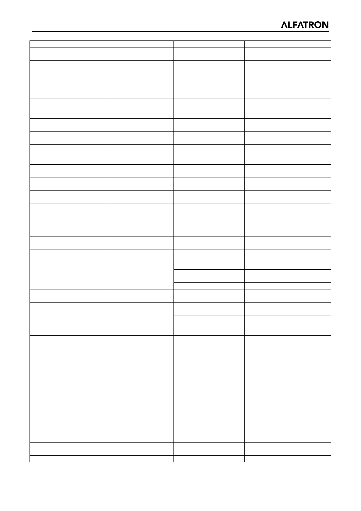
ALFATRON ALF-3XUSB2C
y0 50 0D FF
Bright
CAM_ShutterPosInq
8x 09 04 4A FF
y0 50 00 00 0p 0q FF
pq: Shutter Position
CAM_IrisPosInq
8x 09 04 4B FF
y0 50 00 00 0p 0q FF
pq: Iris Position
CAM_Gain LimitInq
8x 09 04 2C FF
y0 50 0p FF
p: Gain Positon
CAM_ BrightPosiInq
8x 09 04 4D FF
y0 50 00 00 0p 0q FF
pq: Bright Position
y0 50 03 FF
Off
CAM_ExpCompPosInq
8x 09 04 4E FF
y0 50 00 00 0p 0q FF
pq: ExpComp Position
y0 50 02 FF
On
y0 50 03 FF
Off
CAM_WDRStrengthInq
8x 09 04 51 FF
y0 50 00 00 00 0p FF
p: WDR Strength
CAM_NRLevel(2D) Inq
8x 09 04 53 FF
y0 50 0p FF
P: 2DNRLevel
CAM_NRLevel(3D) Inq
8x 09 04 54 FF
y0 50 0p FF
P:3D NRLevel
p: Flicker Settings(0: OFF, 1:
50Hz, 2:60Hz)
CAM_ApertureInq
8x 09 04 42 FF
y0 50 00 00 0p 0q FF
pq: Aperture Gain
y0 50 00 FF
Off
y0 50 04 FF
B&W
p: Memory number last
operated.
y0 50 02 FF
On
y0 50 03 FF
Off
y0 50 02 FF
On
y0 50 03 FF
Off
y0 50 02 FF
On
y0 50 03 FF
Off
p: Color Gain setting 0h (60%) to
Eh (130%)
CAM_IDInq
8x 09 04 22 FF
y0 50 0p FF
p: Gamma ID
y0 50 02 FF
On
y0 50 03 FF
Off
y0 07 7D 01 04 00 FF
Power ON/OFF
y0 07 7D 01 04 07 FF
Zoom tele/wide
y0 07 7D 01 04 38 FF
AF ON/OFF
y0 07 7D 01 04 33 FF
Camera _Backlight
y0 07 7D 01 04 3F FF
Camera _Memery
y0 07 7D 01 06 01 FF
Pan_titleDriver
CAM_BrightnessInq
8x 09 04 A1 FF
y0 50 00 00 0p 0q FF
pq: Brightness Position
CAM_ContrastInq
8x 09 04 A2 FF
y0 50 00 00 0p 0q FF
pq: Contrast Position
y0 50 00 FF
Off
y0 50 01 FF
Flip-H
y0 50 02 FF
Flip-V
y0 50 03 FF
Flip-HV
CAM_GammaInq
8x 09 04 5B FF
y0 50 0p FF
p: Gamma setting
ab cd : vender ID ( 0220 )
vw : reserve
P: 0~E Video format
1080P29.97
7:1080P25
ww: Pan Max Speed zz: Tilt
Max Speed
Pan-tiltPosInq
8x 09 06 12 FF
y0 50 0w 0w 0w 0w
wwww: Pan Position zzzz:
CAM_ExpCompModeInq 8x 09 04 3E FF
CAM_BacklightModeInq 8x 09 04 33 FF
CAM_FlickerModeInq 8x 09 04 55 FF y0 50 0p FF
CAM_PictureEffectModeInq 8x 09 04 63 FF
CAM_MemoryInq 8x 09 04 3F FF y0 50 0p FF
SYS_MenuModeInq 8x 09 06 06 FF
CAM_LR_ReverseInq 8x 09 04 61 FF
CAM_PictureFlipInq 8x 09 04 66 FF
CAM_ColorSaturationInq 8x 09 04 49 FF y0 50 00 00 00 0p FF
IR_ReceiveInq 8x 09 06 08 FF
y0 50 02 FF On
IR_ReceiveReturn
CAM_FlipInq 8x 09 04 A4 FF
CAM_VersionInq 8x 09 00 02 FF
VideoSystemInq 8x 09 06 23 FF y0 50 0p FF
Pan-tiltMaxSpeedInq 8x 09 06 11 FF y0 50 ww zz FF
y0 50 ab cd
mn pq rs tu vw FF
mn pq : model ID ST ( 0510 ) 、
U2 (0512) 、U3 (0513)
rs tu : ARM Version
0:1080P60
8:720P30
1:1080P50
9:720P25
2:1080i60 A:1080P59.94
3:1080i50 B:1080i59.94
4:720P60 C:720P59.94
5:720P50 D:
6:1080P30 E:720P29.97
28
Page 30
ALFATRON ALF-3XUSB2C
0z 0z 0z 0z FF
Tilt Position
Note: [X] in the above table indicates the camera address to be operated,【y】=【x + 8】.
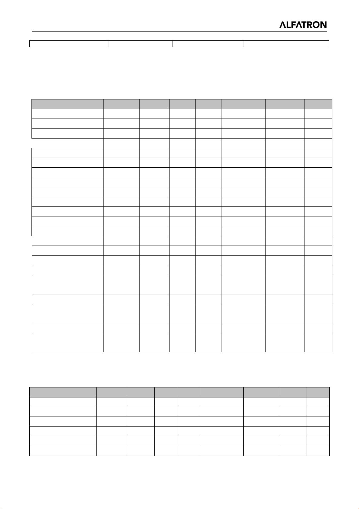
4.2 Pelco-D Protocol Command List
Function Byte1 Byte2 Byte3 Byte4 Byte5 Byte6 Byte7
Up 0xFF Address 0x00 0x08 Pan Speed Tilt Speed SUM
Down 0xFF Address 0x00 0x10 Pan Speed Tilt Speed SUM
Left 0xFF Address 0x00 0x04 Pan Speed Tilt Speed SUM
Right 0xFF Address 0x00 0x02 Pan Speed Tilt Speed SUM
Upleft 0xFF Address 0x00 0x0C Pan Speed Tilt Speed SUM
Upright 0xFF Address 0x00 0x0A Pan Speed Tilt Speed SUM
DownLeft 0xFF Address 0x00 0x14 Pan Speed Tilt Speed SUM
DownRight 0xFF Address 0x00 0x12 Pan Speed Tilt Speed SUM
Zoom In 0xFF Address 0x00 0x20 0x00 0x00 SUM
Zoom Out 0xFF Address 0x00 0x40 0x00 0x00 SUM
Focus Far 0xFF Address 0x00 0x80 0x00 0x00 SUM
Focus Near 0xFF Address 0x01 0x00 0x00 0x00 SUM
Stop 0xFF Address 0x00 0x00 0x00 0x00 SUM
Set Preset 0xFF Address 0x00 0x03 0x00 Preset ID SUM
Clear Preset 0xFF Address 0x00 0x05 0x00 Preset ID SUM
Call Preset 0xFF Address 0x00 0x07 0x00 Preset ID SUM
Query Pan Position 0xFF Address 0x00 0x51 0x00 0x00 SUM
Query Pan Position
Response
Query Tilt Position 0xFF Address 0x00 0x53 0x00 0x00 SUM
Query Tilt Position
Response
Query Zoom Position 0xFF Address 0x00 0x55 0x00 0x00 SUM
Query Zoom Position
Response
0xFF Address 0x00 0x59
0xFF Address 0x00 0x5B
0xFF Address 0x00 0x5D
Value High
Byte
Value High
Byte
Value High
Byte
Value Low
Byte
Value Low
Byte
Value Low
Byte
SUM
SUM
SUM
4.3 Pelco-P Protocol Command List
Function Byte1 Byte2 Byte3 Byte4 Byte5 Byte6 Byte7 Byte8
Up 0xA0 Address 0x00 0x08 Pan Speed Tilt Speed 0xAF XOR
Down 0xA0 Address 0x00 0x10 Pan Speed Tilt Speed 0xAF XOR
Left 0xA0 Address 0x00 0x04 Pan Speed Tilt Speed 0xAF XOR
Right 0xA0 Address 0x00 0x02 Pan Speed Tilt Speed 0xAF XOR
Upleft 0xA0 Address 0x00 0x0C Pan Speed Tilt Speed 0xAF XOR
Upright 0xA0 Address 0x00 0x0A Pan Speed Tilt Speed 0xAF XOR
29
Page 31
ALFATRON ALF-3XUSB2C
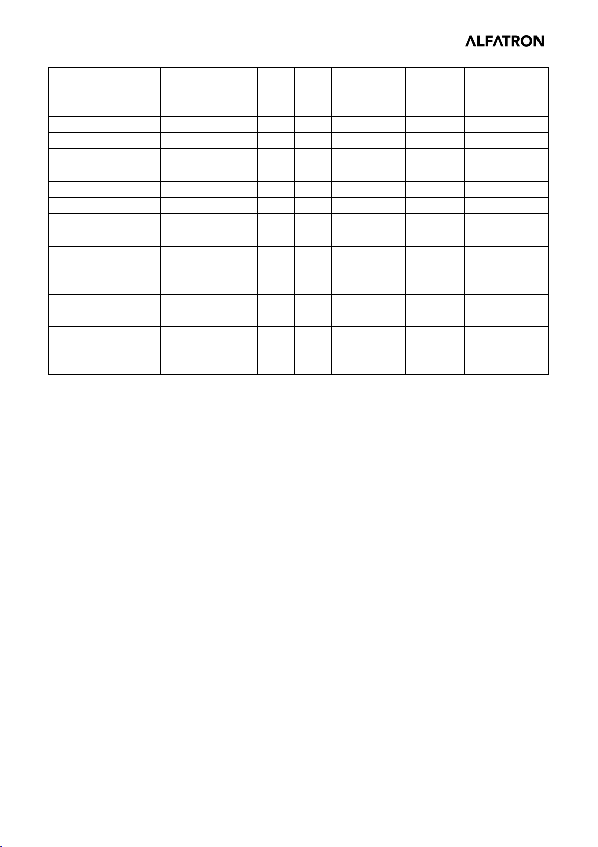
DownLeft 0xA0 Address 0x00 0x14 Pan Speed Tilt Speed 0xAF XOR
DownRight 0xA0 Address 0x00 0x12 Pan Speed Tilt Speed 0xAF XOR
Zoom In 0xA0 Address 0x00 0x20 0x00 0x00 0xAF XOR
Zoom Out 0xA0 Address 0x00 0x40 0x00 0x00 0xAF XOR
Stop 0xA0 Address 0x00 0x00 0x00 0x00 0xAF XOR
Focus Far 0xA0 Address 0x01 0x00 0x00 0x00 0xAF XOR
Focus Near 0xA0 Address 0x02 0x00 0x00 0x00 0xAF XOR
Set Preset 0xA0 Address 0x00 0x03 0x00 Preset ID 0xAF XOR
Clear Preset 0xA0 Address 0x00 0x05 0x00 Preset ID 0xAF XOR
Call Preset 0xA0 Address 0x00 0x07 0x00 Preset ID 0xAF XOR
Query Pan Position 0xA0 Address 0x00 0x51 0x00 0x00 0xAF XOR
Query Pan Position
Response
Query Tilt Position 0xA0 Address 0x00 0x53 0x00 0x00 0xAF XOR
Query Tilt Position
Response
Query Zoom Position 0xA0 Address 0x00 0x55 0x00 0x00 0xAF XOR
Query Zoom Position
Response
0xA0 Address 0x00 0x59
0xA0 Address 0x00 0x5B
0xA0 Address 0x00 0x5D
Value High
Byte
Value High
Byte
Value High
Byte
Value Low
Byte
Value Low
Byte
Value Low
Byte
0xAF XOR
0xAF XOR
0xAF XOR
30
Page 32

ALFATRON ALF-3XUSB2C
5. Maintenance and Troubleshooting
5.1 Camera Maintenance
1) Please power off the camera and disconnect the power adapter from the electrical outlet socket, if it
is not in use for extended periods of time.
2) Use a soft cloth or tissue to clean the camera cover.
3) Wipe with a soft, dry cloth when cleaning the camera lens. Wipe it gently with a mild detergent if
needed. Do not use strong or corrosive detergents to avoid scratching the lens and affecting the
video quality.
5.2 Troubleshooting
1) No video output
a. Check whether the camera power supply is connected, if the voltage is normal, and if the power
indicator is lit.
b. Whether the camera can do a self-check after it has restarted.
c. Check whether the bottom of the DIP switch is in the normal operating mode (see Table 2.2 and
Table 2.3)
d. Check whether the video output cable is connected
2) No image sometimes
a. Check whether the video output cable is connected
3) Video dithering when zoom-in or zoom-out
a. Check whether the camera is installed on a solid base
b. Is there an object around the camera that can cause it to shake
4) Remote control does not work
a. Remote control address is set to 1 (if the machine is set back to the factory defaults, remote control
addresses need to be back to 1)
b. Check whether the battery is installed on the remote controller or if the battery is low.
c. Check that the camera working mode is in the normal operating mode (see Table 2.2 and Table 2.3)
d. Check that the menu is not open, camera control through remote controller is only available after
exiting the menu. If the video is output from LAN, the menu will not be displayed, menu will
automatically show 30s later, and then it can be controlled by remote controller.
5) Serial port not working
a. Check whether the camera serial device protocol, baud rate, and address is correct.
b. Check whether the control cable is connected properly
c. Check whether the camera is in normal working mode (see Table 2.2 and Table 2.3)
31
Page 33

ALFATRON ALF-3XUSB2C
6. Warranty
Limited warranty in respect of Alfatron Products
1.1 This limited warranty covers defects in materials and workmanship in this product.
1.2 Should warranty service be required, proof of purchase must be presented to the Company. The
serial number on the product must be clearly visible and not have been tampered with in any way
whatsoever.
1.3 This limited warranty does not cover any damage, deterioration or malfunction resulting from any
alteration, modification, improper or unreasonable use or maintenance, misuse, abuse, accident, neglect,
exposure to excess moisture, fire, improper packing and shipping (such claims must be presented to the
carrier), lightning, power surges, or other acts of nature. This limited warranty does not cover any
damage, deterioration or
malfunction resulting from the installation or removal of this product from any installation, any
unauthorized tampering with this product, any repairs attempted by anyone unauthorized by the
Company to make such repairs, or any other cause which does not relate directly to a defect in materials
and/or workmanship of this product. This limited warranty does not cover equipment enclosures, cables
or accessories used in conjunction with this product.
This limited warranty does not cover the cost of normal maintenance. Failure of the product due to
insufficient or improper maintenance is not covered.
1.4 The Company does not warrant that the product covered hereby, including, without limitation, the
technology and/or integrated circuit(s) included in the product, will not become obsolete or that such
items are or will remain compatible with any other product or technology with which the product may be
used.
1.5 Only the original purchaser of this product is covered under this limited warranty. This limited
warranty is not transferable to subsequent purchasers or owners of this product.
1.6 Unless otherwise specified, the goods are warranted in accordance with the manufacturer’s product
specific warranties against any defect attributable to faulty workmanship or materials, fair wear and tear
being excluded.
1.7 This limited warranty only covers the cost of faulty goods and does not include the cost of labor and
travel to return the goods to the Company’s premises.
1.8 In the event of any improper maintenance, repair or service being carried out by any third persons
during the warranty period without the Company’s written authorization, the limited warranty shall be
void.
1.9 A 7 (seven) year limited warranty is given on the aforesaid product where used correctly according to
the Company’s instructions, and only with the use of the Company’s components.
1.10 The Company will, at its sole option, provide one of the following three remedies to whatever extent
it shall deem necessary to satisfy a proper claim under this limited warranty:
1.10.1 Elect to repair or facilitate the repair of any defective parts within a reasonable period of time, free
of any charge for the necessary parts and labor to complete the repair and restore this product to its
proper operating condition.; or
1.10.2 Replace this product with a direct replacement or with a similar product deemed by the Company
to perform substantially the same function as the original product; or
32
Page 34

ALFATRON ALF-3XUSB2C
1.10.3 Issue a refund of the original purchase price less depreciation to be determined based on the age
of the product at the time remedy is sought under this limited warranty.
1.11 The Company is not obligated to provide the Customer with a substitute unit during the limited
warranty period or at any time thereafter.
1.12 If this product is returned to the Company this product must be insured during shipment, with the
insurance and shipping charges prepaid by the Customer. If this product is returned uninsured, the
Customer assumes all risks of loss or damage during shipment. The Company will not be responsible for
any costs related to the removal or re-installation of this product from or into any installation. The
Company will not be responsible for any costs related to any setting up this product, any adjustment of
user controls or any programming required for a specific installation of this product.
1.13 Please be aware that the Company’s products and components have not been tested with
competitor’s products and therefore the Company cannot warrant products and/or components used in
conjunction with competitor’s products.
1.14 The appropriateness of the goods for the purpose intended is only warranted to the extent that the
goods are used in accordance with the Company’s installation, classification and usage instructions.
1.15 Any claim by the Customer which is based on any defect in the quality or condition of the goods or
their failure to correspond with specification shall be notified in writing to the Company within 7 days of
delivery or (where the defect or failure was not apparent on reasonable inspection by the Customer)
within a reasonable time after discovery of the defect or failure, but, in any event, within 6 months of
delivery.
1.16 If delivery is not refused, and the Customer does not notify the Company accordingly, the Customer
may not reject the goods and the Company shall have no liability and the Customer shall pay the price as
if the goods had been delivered in accordance with the Agreement.
1.17 THE MAXIMUM LIABILITY OF THE COMPANY UNDER THIS LIMITED WARRANTY SHALL
NOT EXCEED THE ACTUAL PURCHASE PRICE PAID FOR THE PRODUCT
33
 Loading...