


Oil AlertTM
Models - 7410, 7411, 7412, 7413
Operation, Maintenance and Installation Manual
Introduction
Before proceeding with the installation or operation of the Oil Alert System, read all instructions thoroughly, as well as complying with all Federal, State and Local codes, Regulations and Practices. The Oil Alert must be installed by qualified personnel familiar with all applicable local electrical and mechanical codes. Refer to the National Electrical Code (NFPA 70). Failure to properly install and test this product can result in personal injury or equipment malfunction.
The Oil Alert control system is designed and approved for the safe operation of pumping, alarming and monitoring elevator sump pits, transformer vaults and leachate well applications. The Oil Alert will activate a pump to remove water from elevator pits in accordance with ASME A17.1. The Oil Alert stops the pump before oil or other harmful substances enter our water supply. Indicator lights will illuminate on the control panel for the following: power, pump running, high water, high oil and pump overload (optional). The panel has a set of auxiliary contacts that activate on power loss or high Oil/Water conditions. These contacts can be connected to the Oil Alert remote panel which contains audio/visual alarming along with auxiliary contacts for connection to building automation system or SCADA system.
Safety Guidelines
1.DO NOT USE WITH FLAMMABLE OR EXPLOSIVE FLUIDS SUCH AS GASOLINE, FUEL OIL, KEROSENE, ETC. DO NOT USE IN EXPLOSIVE ATMOSPHERES. PROBE/FLOAT SWITCH SHOULD ONLY BE USED WITH WATER.
2.DO NOT HANDLE THE OIL ALERT SYSTEM WITH WET HANDS OR WHEN STANDING ON A WET OR DAMP SURFACE OR IN WATER.
3.DISCONNECT ALL ELECTRICAL SERVICE BEFORE WORKING OR HANDLING THE OIL ALERT SYSTEM.
4.INCOMING VOLTAGE MUST MATCH OIL ALERT SYSTEM VOLTAGE.
5.TO PREVENT ELECTICAL SHOCK AND EQUIPMENT MALFUNCTION, USE ONLY WITH A PUMP SUPPLIED WITH A GROUNDING CONDUCTOR AND GROUNDING-TYPE ATTACHMENT PLUG. BE CERTAIN TO PLUG THE OIL ALERT PANEL TO A PROPERLY GROUNDED, GROUNDING-TYPE RECEPTACLE.
6.CONTROL PANEL AND ALARM MUST BE MOUNTED INDOORS. FOR OUTDOOR APPLICATIONS CONSULT FACTORY.
7.USE CAUTION WITH MODELS USING AN OVERLOAD RELAY. PUMP MOTOR MAY START IMMEDIATELY WHEN OVERLOAD IS RESET.
8.SECURE LEVEL SENSOR ON DISCHARGE PIPE AT A LEVEL THAT GUARANTEES PARTIAL PUMP SUBMERGENCE WHEN WATER LEVEL IS JUST BELOW THE “OFF” PROBE (THE LONGEST PROBE / See Figures 6 and 7 on Page 4 of this manual). FAILURE TO PROPERLY MOUNT THE LEVEL SENSOR MAY CAUSE THE PUMP TO ACTIVATE EVEN WHEN OIL IS PRESENT IN THE SUMP.
9.CAUTION! REMOVE ANY FLOAT SWITCH THAT IS CURRENTLY USED OR SUPPLIED WITH THE PUMP. IF THE FLOAT CANNOT BE REMOVED, SECURE SWITCH SO THAT IT IS ALWAYS ON.
Important
REFER TO THE INCLUDED ELECTRICAL SCHEMATIC FOR ALL INCOMING POWER CONNECTIONS AND PUMP CONNECTIONS WHICH MAY INCLUDE OPTIONAL FIELD WIRING CONNECTIONS
Alarm Systems |
Control Panels |
Float Switches |
Leak Detection Systems |
PN: 102032 |
Page 1 of 10 |
PO Box 827  Hawley, MN 56549
  (218) 483-3034
  Fax (218) 483-3036
  www.alderoind.com
Oil AlertTM
Models - 7410, 7411, 7412, 7413
Operation, Maintenance and Installation Manual
Description of Operation
On water rise, level reaches pump “start” probe to start the pump. Pump will remain on until level is below “off” probe. The “off” probe senses air or oil and turns the pump off so the oil layer will not be pumped out of the sump. If the liquid level reaches alarm probe and mechanical float, the system will differentiate between water and oil and activate the remote alarm.
Installation of the Control Panel
1.It is highly recommended to mount the control panel in the same area as the sump pump to eliminate any splicing of sensor and pump wires. See “Installation of Preset Level Sensor Holder” for more information on splicing. Refer to all Federal, State and local codes.
2.Determine mounting location for the control panel. Mount panel at the desired location making sure the mounting location of the control panel is within 6 feet of electrical receptacle.
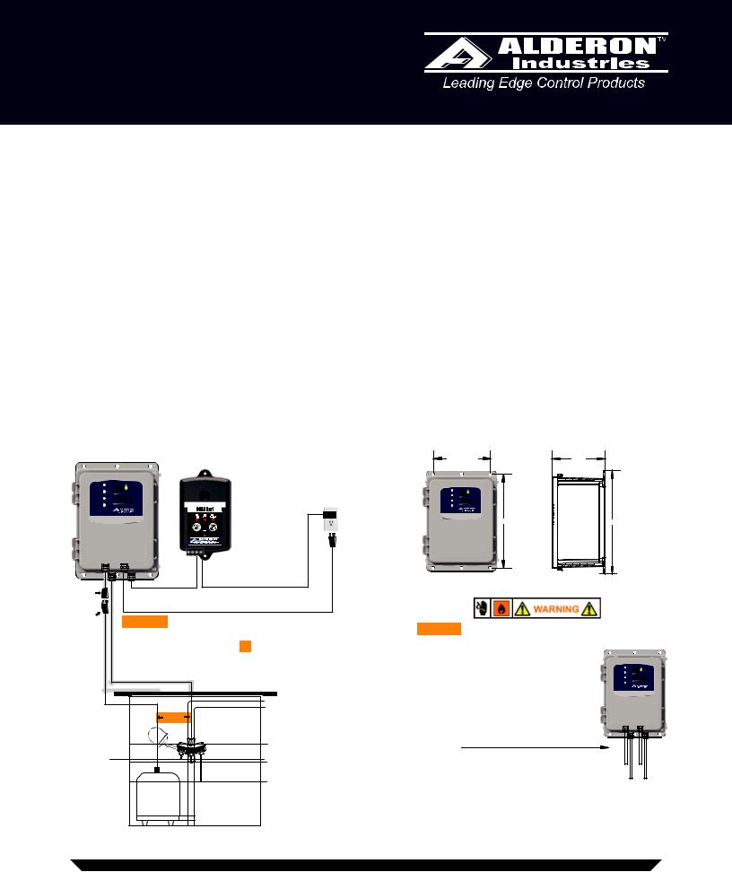
3.Plug pump cable into control panel receptacle cable. Plug power cable into receptacle only when ready for testing. See Testing System installation (Fig. 1).
4.If the panel is to be installed with conduit, the cables and cord seals must first be removed. Please make note of wire locations. The incoming power 115V is connected to L1 and L2 of the contactor, pump receptacle is T1 and T2 on the contactor. Low voltage cable from the level sensing module: Green - TB1 off probe, Yellow - TB2 start probe, Red - TB3 alarm probe, White - TB4 float and Black - TB5 float, TB6 shield. Do not mix low voltage probe wires or auxiliary contacts in high voltage conduits (Fig. 3 & Fig. 8). Note: This manual is also for “4X” models that require conduit. Refer to schematic for electrical connections.
(Fig. 1) |
|
|
(Fig. 2) |
|
|
|
Control Panel |
Remote Alarm has additional |
|
6.56" |
|
4.96" |
|
|
|
|
|
|||
|
Oil |
auxiliary contacts for building |
|
|
|
|
Pump Run |
alarm/automation system. |
Power |
|
|
|
|
Power |
|
|
|
|
|
|
|
TM |
|
Pump Run |
Oil |
|
|
High Water |
Alert |
|
|
Alert |
|
|
|
|
|
High Water |
|
|
|
High Oil |
Pump Control/Alarm System |
|
High Oil |
Pump Control/Alarm System |
|
|
|
|
120 V |
Contact your maintenance manager or local service provider if |
|
|
|
Contact your maintenance manager or local service provider if |
the High Water light or the High Oil light is illuminated. |
11.38” |
12.15” |
|||
the High Water light or the High Oil light is illuminated. |
|
|
||||
|
|
Receptical |
|
|
|
|
A |
C |
|
B |
D |
|
Pump |
Remote Alarm - Plug Into 120V Outlet |
(Fig. 3) |
Receptical |
System Power - Factory Wired To Panel - Plug Models 7410 & 7411 |
|
|
Into 115V Outlet. Plug Models 7412 & 7413 Into 230V Outlet. |
|
Pump Power |
Warning – You must separate the male Power |
|
Warning – Do not mix high and low voltage wires in |
||||||
Plug |
Cord from the pump and the cord of the Preset |
|
|||||||
|
|
the same conduit, failure to do so will cause system |
|||||||
|
Level Sensor by at least 2” whether the cables are |
|
|||||||
|
|
malfunction. The Preset Level Sensor |
|
|
|||||
|
in the tank or when they are above ground in |
|
|
|
|||||
|
|
and Auxiliary Contact wires are low |
Power |
Oil |
|||||
|
separate conduits. |
|
|
Pump Run |
|||||
|
|
|
voltage class 2 wires. Do not install |
High Water |
AlertTM |
||||
|
|
|
|
|
High Oil |
Pump Control/Alarm System |
|||
|
|
|
|
|
sensor cables in conduits with main |
Contact your maintenance manager or local service provider if |
|||
|
|
|
|
|
the High Water light or the High Oil light is illuminated. |
||||
|
|
Discharge Pipe |
|
|
power or pump cables. |
|
|
|
|
|
|
2” |
|
|
|
|
|
||
|
|
|
|
|
|
A |
|
C |
|
|
|
|
|
|
|
|
|
||
|
|
|
|
|
|
|
|
B |
D |
“High” |
|
|
Oil “Film” Detection Level |
Conduit |
|
A |
B |
C D |
|
|
|
Pump“On” Level |
|
|
|
A |
|
C |
|
Water |
|
|
Pump“Off” Level |
|
|
|
|
||
Level |
Pump |
|
|
A Conduit – Low Voltage Pump Cable |
B |
D |
|||
|
|
|
|
|
|
|
|||
|
|
|
|
|
B Conduit – Low Voltage Preset Level Sensor |
|
|
||
|
|
|
|
|
C Conduit – High Voltage Incoming Power Cable |
|
|
||
|
|
|
|
|
D Conduit – High Voltage Auxiliary Contact for Remote Alarm |
||||
Alarm Systems |
Control Panels |
Float Switches |
Leak Detection Systems |
PN: 102032 |
Page 2 of 10 |
||||
PO Box 827  Hawley, MN 56549
  (218) 483-3034
  Fax (218) 483-3036
  www.alderoind.com

Oil AlertTM
Models - 7410, 7411, 7412, 7413
Operation, Maintenance and Installation Manual
Setting the Overload: Models 7411 & 7413
Always refer to the included electrical schematic to verify wiring and function.
An Overload is connected to the bottom of the motor contactor and is used to stop a pump from running if the pump amps exceed the FLA (Full Load Amps) that the pump is rated for. You must set the dial on the overload correctly or your pump will not operate.
BEFORE USING: Set the Overload dial for each pump to the FLA (Full Load Amps) of each pump. Use a phillips head screw driver to adjust the Overload dial (Fig. 4).
Note: If a pump trips reset it by pressing the “RESET” button (Fig. 5).
(Fig. 5)
(Fig. 4)
Note: Other brands of overload relays operate in a similar manner.
Alarm Systems |
Control Panels |
Float Switches |
Leak Detection Systems |
PN: 102032 |
Page 3 of 10 |
PO Box 827  Hawley, MN 56549
  (218) 483-3034
  Fax (218) 483-3036
  www.alderoind.com
 Loading...