

Page 1

SERIES 20000
Return to the Browser Screen
SERVICE MANUAL
™*
LEGACY
®
ALCON SURGICAL
a division of Alcon Laboratories, Inc.
15800 Alton Parkway
Irvine, California 92618-3818 U.S.A.
Telephone: 949/753-1393
800/832-7827
FAX: 949/753-6614
906-2000-501 F, ASSEMBLY
906-2000-001 F, TEXT ONLY
* Reg. U.S. Pat. & TM Off.
©
2002, 1999, 1998, 1997, 1994 Alcon Laboratories, Inc.
Page 2

SERIES 20000
™*
LEGACY
IMPORTANT NOTICE
Equipment improvement is an on-going process and, as such, changes may be made to the equipment after this
manual is printed. Accordingly, Alcon Surgical makes no warranties, expressed or implied, that the information
contained in this service manual is complete or accurate. It is understood that if this manual is used to perform service
on the equipment by other than trained personnel, the user assumes all risks in the use of this manual.
CAUTION
Federal law restricts this device to sale by or on the order of a physician.
Pay close attention to warnings and cautions in this manual. Warnings are written to protect individuals from bodily
injury. Cautions are written to protect the instrument from damage.
®
UNIVERSAL PRECAUTIONS:
Universal precautions shall be observed by all people who come in contact with the instrument and/or accessories to
help prevent their exposure to blood-borne pathogens and/or other potentially infectious materials. In any circumstance, wherein the exact status of blood or body fluids/tissues encountered are unknown, it shall be uniformly
considered potentially infectious and handled accordingly. This is in accordance with OSHA guidelines.
Comments or corrections concerning this manual should be addressed to:
Alcon Surgical
Technical Services Group
PO BOX 19587
Irvine, CA, USA 92623-9587
All rights reserved. No part of this manual may be reproduced, transmitted, or stored in a retrieval system, in any form
or by any means; photocopying, electronic, mechanical, recording, or otherwise; without prior written permission
from Alcon Surgical.
*Registered in the U.S. Patent and Trademark Office.
**MACKOOL is a trademark of Richard J. Mackool, M.D.,
ii 906-2000-501
Page 3

SERIES 20000
™*
LEGACY
®
SERVICE MANUAL
SERIES 20000
™*
LEGACY
®
906-2000-501
MANUAL REVISION RECORD
DATE REVISION REVISED PAGE NUMBERS
08/94 A Initial release
11/94 B Change of binder
12/97 C ECN 33181 - i, iii
7/98 D ECN 34142- Removed Service Test Procedure from Section Four. All pages,
except engineering drawings in Sections Six & Seven, changed to update trademarks and area codes.
11/99 E ECN 99200934
General update and edit to cover all configurations of the STTL:
Section One - updated with information from latest Operator's Manual;
Section Two - added Steerable I/A, and updated remaining theory and block diagrams;
Section Three - added disassembly procedures for various LCD's and new handpiece
connector panel;
Section Five - updated supplies, tools, and spares tables, expanded tables for fault,
warning, and advisory messages, updated troubleshooting table, added system
configuration table;
Sections Six and Seven - updated all drawings and parts lists;
Section Eight - added service information for the VideOverlay Parameters System.
05/2002 F ECN 20022436
General update and edit to cover all configurations of the STTL:
Section One - updated with information from latest Operator's Manual.
Section Two - added NeoSonix™* information and new phaco block diagram.
Section Three - added notes for upgraded systems.
Section Four - removed this section (Service Test Procedure) and renumbered
subsequent sections.
Section Five - renumbered to Section Four, updated supplies, tools, and spares tables,
added POST codes for new CPU, updated system configuration table.
Sections Six and Seven - renumbered to Sections Five and Six, updated all drawings and
parts lists, added drawings for new configurations.
Section Eight - renumbered to Section Seven.
906-2000-501 iii
Page 4

SERIES 20000
TABLE OF CONTENTS
TOPIC PAGE #
SECTION ONE - GENERAL INFORMATION
About This Manual. . . . . . . . . . . . . . . . . . . . . . . . . . . . . . . . . . . . . . . . . . . . . . . . . . . . . . . . . . . . . . . . . . . 1-1
Reference Documents. . . . . . . . . . . . . . . . . . . . . . . . . . . . . . . . . . . . . . . . . . . . . . . . . . . . . . . . . . . . . . . . . 1-2
Receiving Inspection . . . . . . . . . . . . . . . . . . . . . . . . . . . . . . . . . . . . . . . . . . . . . . . . . . . . . . . . . . . . . . . . . 1-2
Unpacking and Setting Up the System. . . . . . . . . . . . . . . . . . . . . . . . . . . . . . . . . . . . . . . . . . . . . . . . . . . . 1-2
Cautery, Diathermy, Coagulation. . . . . . . . . . . . . . . . . . . . . . . . . . . . . . . . . . . . . . . . . . . . . . . . . . . . . . . . 1-6
Electronic System. . . . . . . . . . . . . . . . . . . . . . . . . . . . . . . . . . . . . . . . . . . . . . . . . . . . . . . . . . . . . . . . . . . . 1-6
System Design . . . . . . . . . . . . . . . . . . . . . . . . . . . . . . . . . . . . . . . . . . . . . . . . . . . . . . . . . . . . . . . . . . . . . . 1-6
Front Panel . . . . . . . . . . . . . . . . . . . . . . . . . . . . . . . . . . . . . . . . . . . . . . . . . . . . . . . . . . . . . . . . . . . . . 1-6
Cassette Housing . . . . . . . . . . . . . . . . . . . . . . . . . . . . . . . . . . . . . . . . . . . . . . . . . . . . . . . . . . . . . . . . 1-10
Connector Panel . . . . . . . . . . . . . . . . . . . . . . . . . . . . . . . . . . . . . . . . . . . . . . . . . . . . . . . . . . . . . . . . 1-10
Rear Panel . . . . . . . . . . . . . . . . . . . . . . . . . . . . . . . . . . . . . . . . . . . . . . . . . . . . . . . . . . . . . . . . . . . . . 1-10
Other Features . . . . . . . . . . . . . . . . . . . . . . . . . . . . . . . . . . . . . . . . . . . . . . . . . . . . . . . . . . . . . . . . . . 1-11
Audible Tones . . . . . . . . . . . . . . . . . . . . . . . . . . . . . . . . . . . . . . . . . . . . . . . . . . . . . . . . . . . . . . . . . . . . . 1-12
Remote Control . . . . . . . . . . . . . . . . . . . . . . . . . . . . . . . . . . . . . . . . . . . . . . . . . . . . . . . . . . . . . . . . . . . . 1-12
Modes and Functions . . . . . . . . . . . . . . . . . . . . . . . . . . . . . . . . . . . . . . . . . . . . . . . . . . . . . . . . . . . . . . . . 1-14
Irrigation (Irr) Mode . . . . . . . . . . . . . . . . . . . . . . . . . . . . . . . . . . . . . . . . . . . . . . . . . . . . . . . . . . . . . 1-14
Hydrosonics™* (Hydro) Mode. . . . . . . . . . . . . . . . . . . . . . . . . . . . . . . . . . . . . . . . . . . . . . . . . . . . . 1-16
AdvanTec Mode . . . . . . . . . . . . . . . . . . . . . . . . . . . . . . . . . . . . . . . . . . . . . . . . . . . . . . . . . . . . . . . . 1-16
Ultrasound (U/S) Mode . . . . . . . . . . . . . . . . . . . . . . . . . . . . . . . . . . . . . . . . . . . . . . . . . . . . . . . . . . . 1-19
Irrigation/Aspiration (I/A) Mode. . . . . . . . . . . . . . . . . . . . . . . . . . . . . . . . . . . . . . . . . . . . . . . . . . . . 1-20
Vitrectomy (Vit) Mode . . . . . . . . . . . . . . . . . . . . . . . . . . . . . . . . . . . . . . . . . . . . . . . . . . . . . . . . . . . 1-22
Coagulation (Coag) Mode . . . . . . . . . . . . . . . . . . . . . . . . . . . . . . . . . . . . . . . . . . . . . . . . . . . . . . . . . 1-23
Custom Mode (for software versions 3.01 and below) . . . . . . . . . . . . . . . . . . . . . . . . . . . . . . . . . . . 1-24
Custom Mode (for software versions 3.12 and above) . . . . . . . . . . . . . . . . . . . . . . . . . . . . . . . . . . . 1-29
Test Mode (for software versions 3.01 and below). . . . . . . . . . . . . . . . . . . . . . . . . . . . . . . . . . . . . . 1-37
Test Mode (for software versions 3.12 and above) . . . . . . . . . . . . . . . . . . . . . . . . . . . . . . . . . . . . . . 1-38
Footswitch . . . . . . . . . . . . . . . . . . . . . . . . . . . . . . . . . . . . . . . . . . . . . . . . . . . . . . . . . . . . . . . . . . . . . . . . 1-40
Handpiece and Tip Descriptions . . . . . . . . . . . . . . . . . . . . . . . . . . . . . . . . . . . . . . . . . . . . . . . . . . . . . . . 1-44
Irrigation Handpiece and Tips . . . . . . . . . . . . . . . . . . . . . . . . . . . . . . . . . . . . . . . . . . . . . . . . . . . . . . 1-44
Ultraflow™* I/A Handpieces and Tips. . . . . . . . . . . . . . . . . . . . . . . . . . . . . . . . . . . . . . . . . . . . . . . 1-44
Reusable I/A Tips . . . . . . . . . . . . . . . . . . . . . . . . . . . . . . . . . . . . . . . . . . . . . . . . . . . . . . . . . . . . . . . 1-45
Ultrasonic Handpiece In U/S Bimodal Mode . . . . . . . . . . . . . . . . . . . . . . . . . . . . . . . . . . . . . . . . . . 1-45
Ultrasonic Handpieces. . . . . . . . . . . . . . . . . . . . . . . . . . . . . . . . . . . . . . . . . . . . . . . . . . . . . . . . . . . . 1-45
Hydrosonics™* Handpiece and Tips . . . . . . . . . . . . . . . . . . . . . . . . . . . . . . . . . . . . . . . . . . . . . . . . 1-46
ATIOP Handpiece . . . . . . . . . . . . . . . . . . . . . . . . . . . . . . . . . . . . . . . . . . . . . . . . . . . . . . . . . . . . . . . 1-47
Coagulation Handpieces . . . . . . . . . . . . . . . . . . . . . . . . . . . . . . . . . . . . . . . . . . . . . . . . . . . . . . . . . . 1-47
Steerable I/A Handpiece . . . . . . . . . . . . . . . . . . . . . . . . . . . . . . . . . . . . . . . . . . . . . . . . . . . . . . . . . . 1-48
Steerable I/A Tip . . . . . . . . . . . . . . . . . . . . . . . . . . . . . . . . . . . . . . . . . . . . . . . . . . . . . . . . . . . . . . . . 1-48
Consumable Pak Configurations . . . . . . . . . . . . . . . . . . . . . . . . . . . . . . . . . . . . . . . . . . . . . . . . . . . . . . . 1-49
Error Processing . . . . . . . . . . . . . . . . . . . . . . . . . . . . . . . . . . . . . . . . . . . . . . . . . . . . . . . . . . . . . . . . . . . . 1-51
System Setup . . . . . . . . . . . . . . . . . . . . . . . . . . . . . . . . . . . . . . . . . . . . . . . . . . . . . . . . . . . . . . . . . . . . . . 1-52
™*
LEGACY
®
SECTION TWO - THEORY OF OPERATION
System Overview . . . . . . . . . . . . . . . . . . . . . . . . . . . . . . . . . . . . . . . . . . . . . . . . . . . . . . . . . . . . . . . . . . . . 2-1
Power Supply . . . . . . . . . . . . . . . . . . . . . . . . . . . . . . . . . . . . . . . . . . . . . . . . . . . . . . . . . . . . . . . . . . . . . . . 2-3
Common Interface Signals . . . . . . . . . . . . . . . . . . . . . . . . . . . . . . . . . . . . . . . . . . . . . . . . . . . . . . . . . . . . . 2-3
Subsystem Kernel Design . . . . . . . . . . . . . . . . . . . . . . . . . . . . . . . . . . . . . . . . . . . . . . . . . . . . . . . . . . . . . 2-4
iv 906-2000-501
Page 5

SERIES 20000
™*
LEGACY
®
TABLE OF CONTENTS
TOPIC PAGE #
Host System . . . . . . . . . . . . . . . . . . . . . . . . . . . . . . . . . . . . . . . . . . . . . . . . . . . . . . . . . . . . . . . . . . . . . . . . 2-5
CPU PCB. . . . . . . . . . . . . . . . . . . . . . . . . . . . . . . . . . . . . . . . . . . . . . . . . . . . . . . . . . . . . . . . . . . . . . . 2-6
Multifunction PCB . . . . . . . . . . . . . . . . . . . . . . . . . . . . . . . . . . . . . . . . . . . . . . . . . . . . . . . . . . . . . . . 2-6
Footswitch Interface . . . . . . . . . . . . . . . . . . . . . . . . . . . . . . . . . . . . . . . . . . . . . . . . . . . . . . . . . . . . . . 2-8
IV Pole PCB . . . . . . . . . . . . . . . . . . . . . . . . . . . . . . . . . . . . . . . . . . . . . . . . . . . . . . . . . . . . . . . . . . . 2-10
Video PCB. . . . . . . . . . . . . . . . . . . . . . . . . . . . . . . . . . . . . . . . . . . . . . . . . . . . . . . . . . . . . . . . . . . . . 2-11
Front Panel Subsystem . . . . . . . . . . . . . . . . . . . . . . . . . . . . . . . . . . . . . . . . . . . . . . . . . . . . . . . . . . . . . . . 2-12
Front Panel Controller PCB . . . . . . . . . . . . . . . . . . . . . . . . . . . . . . . . . . . . . . . . . . . . . . . . . . . . . . . 2-12
Display PCB . . . . . . . . . . . . . . . . . . . . . . . . . . . . . . . . . . . . . . . . . . . . . . . . . . . . . . . . . . . . . . . . . . . 2-13
Remote Control . . . . . . . . . . . . . . . . . . . . . . . . . . . . . . . . . . . . . . . . . . . . . . . . . . . . . . . . . . . . . . . . . 2-14
Remote Control PCB. . . . . . . . . . . . . . . . . . . . . . . . . . . . . . . . . . . . . . . . . . . . . . . . . . . . . . . . . . . . . 2-14
Fluidics Subsystem. . . . . . . . . . . . . . . . . . . . . . . . . . . . . . . . . . . . . . . . . . . . . . . . . . . . . . . . . . . . . . . . . . 2-16
Fluidics Controller PCB . . . . . . . . . . . . . . . . . . . . . . . . . . . . . . . . . . . . . . . . . . . . . . . . . . . . . . . . . . 2-17
Transducer PCB . . . . . . . . . . . . . . . . . . . . . . . . . . . . . . . . . . . . . . . . . . . . . . . . . . . . . . . . . . . . . . . . 2-19
Cassette Type PCB . . . . . . . . . . . . . . . . . . . . . . . . . . . . . . . . . . . . . . . . . . . . . . . . . . . . . . . . . . . . . . 2-19
Fluidics Backplane PCB . . . . . . . . . . . . . . . . . . . . . . . . . . . . . . . . . . . . . . . . . . . . . . . . . . . . . . . . . . 2-19
Anterior Pneumatic Module . . . . . . . . . . . . . . . . . . . . . . . . . . . . . . . . . . . . . . . . . . . . . . . . . . . . . . . . . . . 2-20
Anterior Vit Drive PCB. . . . . . . . . . . . . . . . . . . . . . . . . . . . . . . . . . . . . . . . . . . . . . . . . . . . . . . . . . . 2-20
Anterior Compressor . . . . . . . . . . . . . . . . . . . . . . . . . . . . . . . . . . . . . . . . . . . . . . . . . . . . . . . . . . . . . 2-20
Phaco Subsystem (software V3.01 and below) . . . . . . . . . . . . . . . . . . . . . . . . . . . . . . . . . . . . . . . . . . . . 2-21
Phaco Controller PCB . . . . . . . . . . . . . . . . . . . . . . . . . . . . . . . . . . . . . . . . . . . . . . . . . . . . . . . . . . . . 2-22
U/S Driver PCB. . . . . . . . . . . . . . . . . . . . . . . . . . . . . . . . . . . . . . . . . . . . . . . . . . . . . . . . . . . . . . . . . 2-23
Cautery PCB . . . . . . . . . . . . . . . . . . . . . . . . . . . . . . . . . . . . . . . . . . . . . . . . . . . . . . . . . . . . . . . . . . . 2-26
Phaco Subsystem (software V3.12 and above) . . . . . . . . . . . . . . . . . . . . . . . . . . . . . . . . . . . . . . . . . . . . 2-28
NeoSonix™* Controller PCB . . . . . . . . . . . . . . . . . . . . . . . . . . . . . . . . . . . . . . . . . . . . . . . . . . . . . . 2-29
Cautery PCB . . . . . . . . . . . . . . . . . . . . . . . . . . . . . . . . . . . . . . . . . . . . . . . . . . . . . . . . . . . . . . . . . . . 2-31
Steerable I/A System (Option) . . . . . . . . . . . . . . . . . . . . . . . . . . . . . . . . . . . . . . . . . . . . . . . . . . . . . . . . . 2-32
SECTION THREE - PARTS LOCATION AND DISASSEMBLY
General Information . . . . . . . . . . . . . . . . . . . . . . . . . . . . . . . . . . . . . . . . . . . . . . . . . . . . . . . . . . . . . . . . . . 3-1
Required Tools . . . . . . . . . . . . . . . . . . . . . . . . . . . . . . . . . . . . . . . . . . . . . . . . . . . . . . . . . . . . . . . . . . . . . . 3-1
Skins Removal . . . . . . . . . . . . . . . . . . . . . . . . . . . . . . . . . . . . . . . . . . . . . . . . . . . . . . . . . . . . . . . . . . . . . . 3-1
STTL Disassembly Procedures . . . . . . . . . . . . . . . . . . . . . . . . . . . . . . . . . . . . . . . . . . . . . . . . . . . . . . . . . 3-6
SECTION FOUR - MAINTENANCE AND TROUBLESHOOTING
General Information . . . . . . . . . . . . . . . . . . . . . . . . . . . . . . . . . . . . . . . . . . . . . . . . . . . . . . . . . . . . . . . . . . 4-1
Recommended Supplies (Table 4-1) . . . . . . . . . . . . . . . . . . . . . . . . . . . . . . . . . . . . . . . . . . . . . . . . . . . . . 4-1
Recommended Tools (Table 4-2). . . . . . . . . . . . . . . . . . . . . . . . . . . . . . . . . . . . . . . . . . . . . . . . . . . . . . . . 4-2
Recommended Spares (Table 4-3) . . . . . . . . . . . . . . . . . . . . . . . . . . . . . . . . . . . . . . . . . . . . . . . . . . . . . . . 4-4
System Configurations (Table 4-4) . . . . . . . . . . . . . . . . . . . . . . . . . . . . . . . . . . . . . . . . . . . . . . . . . . . . . . 4-5
Legacy System Fault Messages (Table 4-5). . . . . . . . . . . . . . . . . . . . . . . . . . . . . . . . . . . . . . . . . . . . . . . . 4-6
Legacy System Warning Messages (Table 4-6). . . . . . . . . . . . . . . . . . . . . . . . . . . . . . . . . . . . . . . . . . . . 4-10
Legacy System Advisory Messages (Table 4-7) . . . . . . . . . . . . . . . . . . . . . . . . . . . . . . . . . . . . . . . . . . . 4-14
Troubleshooting (Table 4-8) . . . . . . . . . . . . . . . . . . . . . . . . . . . . . . . . . . . . . . . . . . . . . . . . . . . . . . . . . . 4-18
Maintenance Procedures. . . . . . . . . . . . . . . . . . . . . . . . . . . . . . . . . . . . . . . . . . . . . . . . . . . . . . . . . . . . . . 4-21
1 Replacing CPU PCB Lithium Battery . . . . . . . . . . . . . . . . . . . . . . . . . . . . . . . . . . . . . . . . . . . . 4-21
2 Installing or Upgrading System Software. . . . . . . . . . . . . . . . . . . . . . . . . . . . . . . . . . . . . . . . . . 4-21
3 Cleaning the Touch Screen . . . . . . . . . . . . . . . . . . . . . . . . . . . . . . . . . . . . . . . . . . . . . . . . . . . . . 4-22
4 Cautery Calibration. . . . . . . . . . . . . . . . . . . . . . . . . . . . . . . . . . . . . . . . . . . . . . . . . . . . . . . . . . . 4-22
906-2000-501 v
Page 6

SERIES 20000
TABLE OF CONTENTS
TOPIC PAGE #
Power On Self-Test (Post) Error Codes for CPU PCB's PN 200-1592-001 and
200-1845-001 (Table 4-9) . . . . . . . . . . . . . . . . . . . . . . . . . . . . . . . . . . . . . . . . . . . . . . . . . . . . . . . . . . . . 4-23
Power On Self-Test (Post) Error Codes for CPU PCB PN 200-2290-001 (Table 4-10) . . . . . . . . . . . . . 4-26
SECTION FIVE - SCHEMATICS
Contents . . . . . . . . . . . . . . . . . . . . . . . . . . . . . . . . . . . . . . . . . . . . . . . . . . . . . . . . . . . . . . . . . . . . . . . . . . . 5-1
SECTION SIX - PARTS LISTS AND DRAWINGS
Contents . . . . . . . . . . . . . . . . . . . . . . . . . . . . . . . . . . . . . . . . . . . . . . . . . . . . . . . . . . . . . . . . . . . . . . . . . . . 6-1
SECTION SEVEN - ADDITIONAL INFORMATION
VideOverlay Parameters System . . . . . . . . . . . . . . . . . . . . . . . . . . . . . . . . . . . . . . . . . . . . . . . . . . . . . . . . 7-1
LIST OF ILLUSTRATIONS
TITLE PAGE #
™*
LEGACY
®
Figure 1-1 The Series 20000™* Legacy®. . . . . . . . . . . . . . . . . . . . . . . . . . . . . . . . . . . . . . . . . . . . . . 1-1
Figure 1-2 STTL Packing Configuration . . . . . . . . . . . . . . . . . . . . . . . . . . . . . . . . . . . . . . . . . . . . . . . 1-3
Figure 1-3 Icons used with the STTL . . . . . . . . . . . . . . . . . . . . . . . . . . . . . . . . . . . . . . . . . . . . . . . . . . 1-5
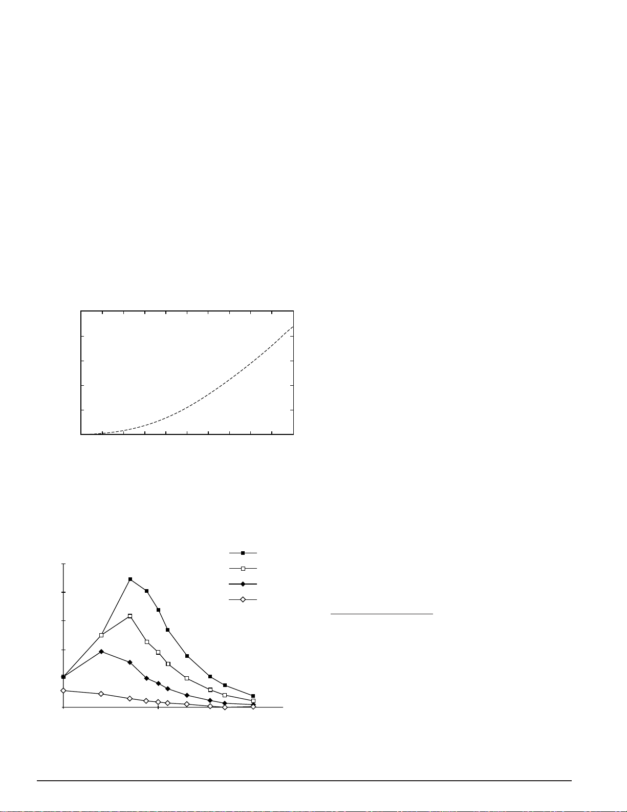
Figure 1-4 Coagulation Power Through 75 Ohm Load . . . . . . . . . . . . . . . . . . . . . . . . . . . . . . . . . . . . 1-6
Figure 1-5 Coagulation Power vs. Load Impedance. . . . . . . . . . . . . . . . . . . . . . . . . . . . . . . . . . . . . . . 1-6
Figure 1-6 Front Control Panel. . . . . . . . . . . . . . . . . . . . . . . . . . . . . . . . . . . . . . . . . . . . . . . . . . . . . . . 1-7
Figure 1-7 Cassette Housing and Connector Panel . . . . . . . . . . . . . . . . . . . . . . . . . . . . . . . . . . . . . . 1-10
Figure 1-8 Series 20000™* Rear View . . . . . . . . . . . . . . . . . . . . . . . . . . . . . . . . . . . . . . . . . . . . . . . 1-11
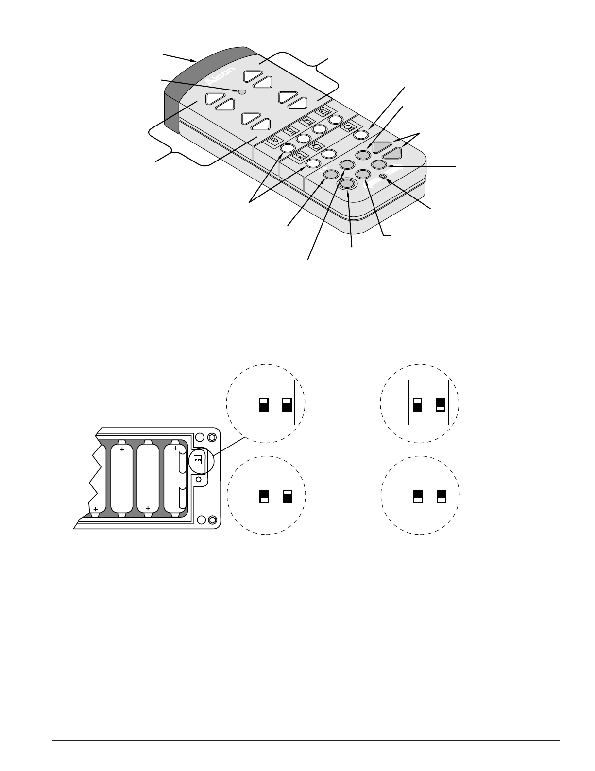
Figure 1-9 Remote Control . . . . . . . . . . . . . . . . . . . . . . . . . . . . . . . . . . . . . . . . . . . . . . . . . . . . . . . . . 1-13
Figure 1-10 Remote Control Switches . . . . . . . . . . . . . . . . . . . . . . . . . . . . . . . . . . . . . . . . . . . . . . . . . 1-13
Figure 1-11 Modes and Submodes . . . . . . . . . . . . . . . . . . . . . . . . . . . . . . . . . . . . . . . . . . . . . . . . . . . . 1-14
Figure 1-12 Irrigation Mode . . . . . . . . . . . . . . . . . . . . . . . . . . . . . . . . . . . . . . . . . . . . . . . . . . . . . . . . . 1-15
Figure 1-13 Footswitch Functions - Hydrosonics™*. . . . . . . . . . . . . . . . . . . . . . . . . . . . . . . . . . . . . . 1-16
Figure 1-14 AdvanTec Visco Mode . . . . . . . . . . . . . . . . . . . . . . . . . . . . . . . . . . . . . . . . . . . . . . . . . . . 1-16
Figure 1-15 Footswitch Functions - AdvanTec . . . . . . . . . . . . . . . . . . . . . . . . . . . . . . . . . . . . . . . . . . 1-17
Figure 1-16 Footswitch Functions - U/S. . . . . . . . . . . . . . . . . . . . . . . . . . . . . . . . . . . . . . . . . . . . . . . . 1-19
Figure 1-17 Footswitch Functions - I/A . . . . . . . . . . . . . . . . . . . . . . . . . . . . . . . . . . . . . . . . . . . . . . . . 1-20
Figure 1-18 Footswitch Functions - Vitrectomy. . . . . . . . . . . . . . . . . . . . . . . . . . . . . . . . . . . . . . . . . . 1-22
Figure 1-19 Footswitch Functions - Coag . . . . . . . . . . . . . . . . . . . . . . . . . . . . . . . . . . . . . . . . . . . . . . 1-23
Figure 1-20 Priming is in Progress . . . . . . . . . . . . . . . . . . . . . . . . . . . . . . . . . . . . . . . . . . . . . . . . . . . . 1-23
Figure 1-21 Custom: Program (V3.01 and below) . . . . . . . . . . . . . . . . . . . . . . . . . . . . . . . . . . . . . . . . 1-24
Figure 1-22 Special I/V Pole Setup (V3.01 and below) . . . . . . . . . . . . . . . . . . . . . . . . . . . . . . . . . . . . 1-25
Figure 1-23 Special Functions: Aspiration (V3.01 and below) . . . . . . . . . . . . . . . . . . . . . . . . . . . . . . 1-25
Figure 1-24 Custom: Sound (V3.01 and below). . . . . . . . . . . . . . . . . . . . . . . . . . . . . . . . . . . . . . . . . . 1-27
Figure 1-25 Custom: Footswitch (V3.01 and below) . . . . . . . . . . . . . . . . . . . . . . . . . . . . . . . . . . . . . . 1-28
Figure 1-26 Custom Mode (V3.12 and above) . . . . . . . . . . . . . . . . . . . . . . . . . . . . . . . . . . . . . . . . . . . 1-29
Figure 1-27 Custom: Program (V3.12 and above) . . . . . . . . . . . . . . . . . . . . . . . . . . . . . . . . . . . . . . . . 1-30
Figure 1-28 Metrics Screen (V3.12 and above) . . . . . . . . . . . . . . . . . . . . . . . . . . . . . . . . . . . . . . . . . . 1-30
Figure 1-29 Special IV Pole Setup (V3.12 and above). . . . . . . . . . . . . . . . . . . . . . . . . . . . . . . . . . . . . 1-32
Figure 1-30 Special Functions: Aspiration (V3.12 and above) . . . . . . . . . . . . . . . . . . . . . . . . . . . . . . 1-32
Figure 1-31 Special Functions: Occlusion (V3.12 and above) . . . . . . . . . . . . . . . . . . . . . . . . . . . . . . . 1-32
Figure 1-32 Custom: Sound (V3.12 and above) . . . . . . . . . . . . . . . . . . . . . . . . . . . . . . . . . . . . . . . . . . 1-35
vi 906-2000-501
Page 7

SERIES 20000
™*
LEGACY
®
LIST OF ILLUSTRATIONS
TITLE PAGE #
Figure 1-33 Custom: Footswitch (V3.12 and above) . . . . . . . . . . . . . . . . . . . . . . . . . . . . . . . . . . . . . . 1-35
Figure 1-34 Custom: Footswitch:Procedure (V3.12 and above) . . . . . . . . . . . . . . . . . . . . . . . . . . . . . 1-36
Figure 1-35 Accurus
Figure 1-36 Footpedal Travel By Mode of Operation . . . . . . . . . . . . . . . . . . . . . . . . . . . . . . . . . . . . . 1-41
Figure 1-37 Irrigation Handpiece and Tips. . . . . . . . . . . . . . . . . . . . . . . . . . . . . . . . . . . . . . . . . . . . . . 1-44
Figure 1-38 Ultraflow™* Handpiece and .3mm Tips (Handpiece Shown with Straight Tip). . . . . . . 1-44
Figure 1-39 Ultraflow™* O-Ring Tool . . . . . . . . . . . . . . . . . . . . . . . . . . . . . . . . . . . . . . . . . . . . . . . . 1-44
Figure 1-40 Ultraflow™* SP Handpiece (Handpiece Shown with .3 mm 45˚ Tip). . . . . . . . . . . . . . . 1-44
Figure 1-41 Reusable I/A Tips And Threaded Tip Adaptor . . . . . . . . . . . . . . . . . . . . . . . . . . . . . . . . . 1-45
Figure 1-42 Ultrasonic Handpiece (375-40) with Infusion Sleeve and Bubble Suppression Insert. . . 1-45
Figure 1-43 Hydrosonics™* Handpiece . . . . . . . . . . . . . . . . . . . . . . . . . . . . . . . . . . . . . . . . . . . . . . . 1-46
Figure 1-44 NeoSonix™* Handpiece. . . . . . . . . . . . . . . . . . . . . . . . . . . . . . . . . . . . . . . . . . . . . . . . . . 1-46
Figure 1-45 ATIOP Handpiece. . . . . . . . . . . . . . . . . . . . . . . . . . . . . . . . . . . . . . . . . . . . . . . . . . . . . . . 1-47
Figure 1-46 4 Inch Nadler Coaptation, 0.4 mm Tip . . . . . . . . . . . . . . . . . . . . . . . . . . . . . . . . . . . . . . . 1-47
Figure 1-47 Disposable Bipolar Brush . . . . . . . . . . . . . . . . . . . . . . . . . . . . . . . . . . . . . . . . . . . . . . . . . 1-47
Figure 1-48 Coagulation Cord . . . . . . . . . . . . . . . . . . . . . . . . . . . . . . . . . . . . . . . . . . . . . . . . . . . . . . . 1-47
Figure 1-49 Steerable I/A Handpiece . . . . . . . . . . . . . . . . . . . . . . . . . . . . . . . . . . . . . . . . . . . . . . . . . . 1-48
Figure 1-50 Steerable I/A Tip . . . . . . . . . . . . . . . . . . . . . . . . . . . . . . . . . . . . . . . . . . . . . . . . . . . . . . . . 1-48
Figure 1-54 Handpiece Tip Styles . . . . . . . . . . . . . . . . . . . . . . . . . . . . . . . . . . . . . . . . . . . . . . . . . . . . 1-49
®
/Legacy® Footswitch . . . . . . . . . . . . . . . . . . . . . . . . . . . . . . . . . . . . . . . . . . . . 1-40
Figure 2-1 Subsystem Locations. . . . . . . . . . . . . . . . . . . . . . . . . . . . . . . . . . . . . . . . . . . . . . . . . . . . . . 2-1
Figure 2-2 System Block Diagram . . . . . . . . . . . . . . . . . . . . . . . . . . . . . . . . . . . . . . . . . . . . . . . . . . . . 2-2
Figure 2-3 CPU-Subsystem Interface . . . . . . . . . . . . . . . . . . . . . . . . . . . . . . . . . . . . . . . . . . . . . . . . . . 2-3
Figure 2-4 Subsystem Kernal Block Diagram . . . . . . . . . . . . . . . . . . . . . . . . . . . . . . . . . . . . . . . . . . . 2-4
Figure 2-5 Host Subsystem. . . . . . . . . . . . . . . . . . . . . . . . . . . . . . . . . . . . . . . . . . . . . . . . . . . . . . . . . . 2-5
Figure 2-6 Fluidics Flow Diagram . . . . . . . . . . . . . . . . . . . . . . . . . . . . . . . . . . . . . . . . . . . . . . . . . . . 2-16
Figure 2-7 Stepper Motor Control Waveform . . . . . . . . . . . . . . . . . . . . . . . . . . . . . . . . . . . . . . . . . . 2-17
Figure 2-8 Vit Air Flow Diagram . . . . . . . . . . . . . . . . . . . . . . . . . . . . . . . . . . . . . . . . . . . . . . . . . . . . 2-20
Figure 2-9 Steerable I/A Control Block Diagram. . . . . . . . . . . . . . . . . . . . . . . . . . . . . . . . . . . . . . . . 2-33
Figure FO-1 Multifunction PCB Block Diagram . . . . . . . . . . . . . . . . . . . . . . . . . . . . . . . . . . . . . . . . . 2-35
Figure FO-2 Footswitch Interface Block Diagram . . . . . . . . . . . . . . . . . . . . . . . . . . . . . . . . . . . . . . . . 2-36
Figure FO-3 IV Pole Interface Block Diagram . . . . . . . . . . . . . . . . . . . . . . . . . . . . . . . . . . . . . . . . . . . 2-37
Figure FO-4 Video PCB Block Diagram. . . . . . . . . . . . . . . . . . . . . . . . . . . . . . . . . . . . . . . . . . . . . . . . 2-38
Figure FO-5 Front Panel Subsystem Block Diagram . . . . . . . . . . . . . . . . . . . . . . . . . . . . . . . . . . . . . . 2-39
Figure FO-6 Fluidics Subsystem Block Diagram . . . . . . . . . . . . . . . . . . . . . . . . . . . . . . . . . . . . . . . . . 2-40
Figure FO-7 Phaco Subsytem Block Diagram (V3.01 and below) . . . . . . . . . . . . . . . . . . . . . . . . . . . . 2-41
Figure FO-8 Phaco Subsytem Block Diagram (V3.12 and above) . . . . . . . . . . . . . . . . . . . . . . . . . . . . 2-42
Figure 3-1 STTL Skins Location Diagram (Front View) . . . . . . . . . . . . . . . . . . . . . . . . . . . . . . . . . . . 3-4
Figure 3-2 STTL Skins Location Diagram (Rear View) . . . . . . . . . . . . . . . . . . . . . . . . . . . . . . . . . . . 3-5
Figure 3-3 Exploded View of the STTL Front Panel Module . . . . . . . . . . . . . . . . . . . . . . . . . . . . . . . 3-6
Figure 3-4 Removal of Backlights from LCD PN 088-032 . . . . . . . . . . . . . . . . . . . . . . . . . . . . . . . . . 3-7
Figure 3-5 Location of LCD Backlights on LCD PN 200-1836-001 . . . . . . . . . . . . . . . . . . . . . . . . . . 3-7
Figure 3-6 Location of LCD Backlights on LCD PN 200-1721-001 . . . . . . . . . . . . . . . . . . . . . . . . . . 3-7
Figure 3-7 Connector Panel . . . . . . . . . . . . . . . . . . . . . . . . . . . . . . . . . . . . . . . . . . . . . . . . . . . . . . . . 3-10
Figure 3-8 Series 20000™* Footswitch . . . . . . . . . . . . . . . . . . . . . . . . . . . . . . . . . . . . . . . . . . . . . . . 3-11
Figure 3-9 STTL Parts Location (Front View). . . . . . . . . . . . . . . . . . . . . . . . . . . . . . . . . . . . . . . . . . 3-12
Figure 3-10 STTL Parts Location (Rear View) . . . . . . . . . . . . . . . . . . . . . . . . . . . . . . . . . . . . . . . . . . 3-13
Figure 3-11 STTL PCB Location . . . . . . . . . . . . . . . . . . . . . . . . . . . . . . . . . . . . . . . . . . . . . . . . . . . . . 3-14
906-2000-501 vii
Page 8

SERIES 20000
™*
LIST OF ILLUSTRATIONS
TITLE PAGE #
Figure 4-1 24 mm Custom Wrench Specifications. . . . . . . . . . . . . . . . . . . . . . . . . . . . . . . . . . . . . . . . 4-3
Figure 4-2 Lithium Battery on CPU PCB. . . . . . . . . . . . . . . . . . . . . . . . . . . . . . . . . . . . . . . . . . . . . . 4-21
Figure 4-3 Disk Insertion . . . . . . . . . . . . . . . . . . . . . . . . . . . . . . . . . . . . . . . . . . . . . . . . . . . . . . . . . . 4-21
Figure 7-1Rear Panel - Videoverlay. . . . . . . . . . . . . . . . . . . . . . . . . . . . . . . . . . . . . . . . . . . . . . . . . . 7-1
Figure 7-2RCA to SVHS Adaptor Cables Setup. . . . . . . . . . . . . . . . . . . . . . . . . . . . . . . . . . . . . . . . . 7-2
Figure 7-3Standard Interconnect (Using RCA To SVHS Adaptor Cables). . . . . . . . . . . . . . . . . . . . 7-3
Figure 7-4Super VHS High-Resolution Setup (Using Customer-Supplied SVHS Video Cables). . . 7-5
Figure 7-5VideOverlay Block Diagram. . . . . . . . . . . . . . . . . . . . . . . . . . . . . . . . . . . . . . . . . . . . . . . 7-6
LIST OF TABLES
TITLE PAGE #
Table 1-1 Series 20000™* Legacy® Performance Specifications . . . . . . . . . . . . . . . . . . . . . . . . . . . 1-4
Table 1-2 Audible Tones . . . . . . . . . . . . . . . . . . . . . . . . . . . . . . . . . . . . . . . . . . . . . . . . . . . . . . . . . . 1-12
Table 1-3 Footpedal Travel in Enhanced Modes . . . . . . . . . . . . . . . . . . . . . . . . . . . . . . . . . . . . . . . 1-27
Table 1-4 Various Memory Settings . . . . . . . . . . . . . . . . . . . . . . . . . . . . . . . . . . . . . . . . . . . . . . . . . 1-31
Table 1-5 Acceptable Pre-Occlusion/Occlusion Combinations . . . . . . . . . . . . . . . . . . . . . . . . . . . . 1-33
Table 1-6 Footpedal Travel in Enhanced Modes . . . . . . . . . . . . . . . . . . . . . . . . . . . . . . . . . . . . . . . 1-36
Table 1-7 Operation by Mode and Footpedal Position for Software Versions 3.01 and Below . . . . 1-42
Table 1-8 Operation by Mode and Footpedal Position for Software Versions 3.12 and Above. . . . 1-43
LEGACY
®
Table 2-1 U/S Driver PCB Connections . . . . . . . . . . . . . . . . . . . . . . . . . . . . . . . . . . . . . . . . . . . . . . 2-22
Table 2-2 U/S Enable Logic (Low=0, High=1). . . . . . . . . . . . . . . . . . . . . . . . . . . . . . . . . . . . . . . . . 2-24
Table 2-3 NeoSonix™* Controller PCB Connections . . . . . . . . . . . . . . . . . . . . . . . . . . . . . . . . . . . 2-29
Table 2-4 U/S Enabling Logic. . . . . . . . . . . . . . . . . . . . . . . . . . . . . . . . . . . . . . . . . . . . . . . . . . . . . . 2-30
Table 3-1 Skins Removal Instructions . . . . . . . . . . . . . . . . . . . . . . . . . . . . . . . . . . . . . . . . . . . . . . . . 3-2
Table 4-1 Recommended Supplies . . . . . . . . . . . . . . . . . . . . . . . . . . . . . . . . . . . . . . . . . . . . . . . . . . . 4-1
Table 4-2 Recommended Tools. . . . . . . . . . . . . . . . . . . . . . . . . . . . . . . . . . . . . . . . . . . . . . . . . . . . . . 4-2
Table 4-3 Recommended Spares . . . . . . . . . . . . . . . . . . . . . . . . . . . . . . . . . . . . . . . . . . . . . . . . . . . . . 4-4
Table 4-4 System Configurations . . . . . . . . . . . . . . . . . . . . . . . . . . . . . . . . . . . . . . . . . . . . . . . . . . . . 4-5
®
Table 4-5 Legacy
System Fault Messages . . . . . . . . . . . . . . . . . . . . . . . . . . . . . . . . . . . . . . . . . . . . 4-6
Table 4-6 Legacy® System Warning Messages . . . . . . . . . . . . . . . . . . . . . . . . . . . . . . . . . . . . . . . . 4-10
Table 4-7 Legacy® System Advisory Messages . . . . . . . . . . . . . . . . . . . . . . . . . . . . . . . . . . . . . . . . 4-14
Table 4-8 Troubleshooting . . . . . . . . . . . . . . . . . . . . . . . . . . . . . . . . . . . . . . . . . . . . . . . . . . . . . . . . 4-18
Table 4-9 Power On Self-Test (Post) Error Codes for CPU PCB's PN 200-1592-001 and
200-1845-001 . . . . . . . . . . . . . . . . . . . . . . . . . . . . . . . . . . . . . . . . . . . . . . . . . . . . . . . . . . 4-23
Table 4-10 Power On Self-Test (Post) Error Codes for CPU PCB PN 200-2290-001 . . . . . . . . . . . . 4-26
Table 7-1 VideOverlay Display Information . . . . . . . . . . . . . . . . . . . . . . . . . . . . . . . . . . . . . . . . . . . 7-4
viii 906-2000-501
Page 9

SERIES 20000
™*
LEGACY
®
SECTION ONE
GENERAL INFORMATION
Alcon Surgical’s SERIES 20000™* LEGACY
®
(STTL) is a sophisticated ophthalmic surgical instrument
manufactured to be durable, reliable, safe and easy to
operate. This state-of-the-art instrument has been
developed to be user friendly; it combines hardware that
is easy to install and maintain along with computer
software that increases the effectivity of the user.
ABOUT THIS MANUAL...
This manual covers all configurations of the Legacy
®
and is divided into eight sections as follows:
Section One-General Information
This section gives a general description of the STTL
features and components. Also included is an unpacking
and installation procedure.
Section Two-Theory of Operation
This section gives a detailed description of how the
STTL operates starting at the system level and working
down to the PCB (Printed Circuit Board) level. Detailed
block diagrams are provided at the end of this section.
Section Three-Parts Location and Disassembly
This section contains parts location diagrams along with
field level disassembly procedures.
Section Four-Maintenance & Troubleshooting
This section contains system maintenace procedures and
troubleshooting information.
Figure 1-1 The Series 20000™* Legacy
Section Five-Schematics
This section contains the system interconnect diagram,
PCB assembly drawings, and schematic diagrams.
Section Six-Parts Lists and Drawings
This section contains parts lists, engineering
documentation for each major assembly, and cable
drawings.
Section Seven-Additional Information
This section contains information on accessories or
optional equipment that may require service.
®
906-2000-501 1-1
Page 10

SERIES 20000
™*
LEGACY
®
REFERENCE DOCUMENTS
Although this manual provides the necessary information
for maintaining optimum performance of the STTL, it
does not contain all of the operating procedures or
functional descriptions contained in the Operator's
Manual. In addition, the Warnings and Cautions in the
Operator's Manual also apply for this Service Manual.
The Operator's Manual supplements information
provided in this manual and should be available on-site
with the system.
If you have any questions or require additional
information, please contact your local Service
Representative or the Technical Services Department at:
ALCON SURGICAL
15800 Alton Parkway
Irvine, CA 92618
(949) 753-1393
(800) 832-7827
If you are located outside the United States, please
contact your local authorized Alcon Surgical distributor.
CAUTION
Federal Law restricts this device to sale by or on the
order of a physician.
RECEIVING INSPECTION
The system was inspected mechanically and electrically
prior to shipment. If the shipping container appears
damaged, ask that the carrier’s agent be present when the
system is unpacked. The system should be inspected for
external damage (i.e. scratches, dents, or broken parts).
If damage is discovered or if the system fails any of the
functional tests notify the carrier and an Alcon Surgical
representative. Retain the shipping container and
packing material for the carrier’s inspection. As
necessary, file a claim with the carrier or, if insured
separately, with the insurance company.
UNPACKING AND SETTING UP THE SYSTEM
1 Cut and remove the binding straps.
2 Remove the outer sleeve and rails from the shipping
carton (see Figure 1-2 for packing configuration).
3 Remove the accessory box, foam inserts, and
footswitch. Inspect for signs of damage.
4 Carefully tip the shipping carton so as to place the
system in an upright position .
END USER LICENSE AGREEMENT:
This product contains software licensed from Microsoft
Corporation.
5 Roll the system out of the container, remove the
antistatic cover, and inspect the system for signs of
shipping damage.
6 Unwrap the footswitch and plug it into the
appropriate connector on the rear panel.
7 Release the tray arm and pull it out of the storage
position. Remove the instrument tray and remote
control from the accessory box. Open the remote
control back cover and install the batteries.
8 Snap the instrument tray into position on the tray
arm. Place the remote control in the recessed area of
the instrument tray.
9 Release the 115 VAC power cord from the Rear
Panel and plug into a functioning 115 VAC
receptacle but do not turn on the AC Power Switch
or the Stand-by Switch until instructed to do so.
10 Perform the STTL Service Test Procedure.
1-2 906-2000-501
Page 11

SERIES 20000
™*
LEGACY
®
Figure 1-2 STTL Packing Configuration
906-2000-501 1-3
Page 12

SERIES 20000
TABLE 1-1. SERIES 20000™* LEGACY® PERFORMANCE SPECIFICATIONS
™*
LEGACY
®
ELECTRICAL
The system will auto-select between the following
voltage:
100 Vac nominal ( 88-110 Vac), 47-63 Hz, single ø
120 Vac nominal (102-132 Vac), 47-63 Hz, single ø
220 Vac nominal (176-242 Vac), 47-63 Hz, single ø
240 Vac nominal (204-270 Vac), 47-63 Hz, single ø
Maximum power ........................................ ≤ 523 Watts
LEAKAGE CURRENT
< 100 µA @120 VAC, per NFPA99
< 500 µA @264 VAC, per IEC-60601-1,
Edition 2 (includes power cord)
(includes power cord)
VOLTAGE NO-LOAD
+5V ............................................................. +5.10 ± .05
+12V ......................................................... +12.00 ± .12
+15V ......................................................... +15.00 ± .15
-15V ........................................................... -15.00 ± .15
+24V ......................................................... +24.00 ± .24
+85V ......................................................... +85.00 ± .85
VOLTAGE UNDER LOAD
+5V ............................................................. +5.10 ± .10
+12V ......................................................... +12.00 ± .20
+15V ......................................................... +15.00 ± .15
-15V ........................................................... -15.00 ± .20
+24V ......................................................... +24.00 ± .24
+85V ......................................................... +85.00 ± .85
IV POLE
Bottle height at retraction ............................. .2 cm ± 1
Bottle height when fully raised (without IV
pole extension) ............................................ 78 cm ± 1
Bottle height at power-up (default) .............. 65 cm ± 1
IV Pole Speed........................................ 10 ± 2 cm/sec
VACUUM ACCURACY
ACTUAL VACUUM DISPLAYED VACUUM
0 mmHg.................................................... 0 ± 2 mmHg
50 mmHg ............................................. 50 ± 2.5 mmHg
200 mmHg.......................................... 200 ± 10 mmHg
400 mmHg.......................................... 400 ± 20 mmHg
500 mmHg.......................................... 500 ± 25 mmHg
VACUUM OCCLUSION
VACUUM SETTING OCCLUSION RANGE
5 mmHg @ 5 cc/min................................. 0-10 mmHg
22 mmHg @ 25 cc/min............................. 7-27 mmHg
48 mmHg @ 25 cc/min........................... 43-53 mmHg
66 mmHg @ 25 cc/min........................... 61-71 mmHg
102 mmHg @ 25 cc/min....................... 92-112 mmHg
400 mmHg @ 25 cc/min..................... 385-415 mmHg
RESIDUAL VACUUM
With irrigation line occluded at the white HP connection
and waiting 3 seconds after the footswitch is released.
VACUUM METER READING
46 mmHg .......................................... 5 mmHg vacuum
400 mmHg...................................... 15 mmHg vacuum
DIMENSIONS
Height .............................................55 inches (138 cm)
Width ................................................20 inches (51 cm)
Depth................................................23 inches (57 cm)
WEIGHT
Unpacked ...................................... 200 pounds (90 kg)
Packed......................................... 275 pounds (125 kg)
ENVIRONMENTAL LIMITATIONS
Altitude
Operating............................8,000 feet (2438 meters)
Non-Operating............... 40,000 feet (12,191 meters)
Temperature
Operating...................... 10°C to 35°C (50°F to 95°F)
Non-Operating.......... -40°C to 75°C (-40°F to 167°F)
Humidity
Operating...................10% to 95% w/o condensation
Non-Operating........... 10% to 95% w/o condensation
ANTERIOR VIT PUMP
Pressure @ 10 CPM ...................... ≥30 psi (pressure)
Vacuum @ 10 CPM.................. ≥450 mmHg (vacuum)
Cut Rate .............................................. 10 to 400 CPM
ULTRASONIC HANDPIECE STROKE
U/S 375-40 ......................... 3.0 to 4.0 mils (maximum)
Hydrosonic.............................................. 1.0 to 1.6mils
NeoSonix™* .............................................. ± 2 degrees
COAGULATION
Frequency............................................... 300-400 KHz
Power @ 100% power using a
75 ohm non-inductive load ...................... 20 ± .5 watts
VIDEO
• 640 x 480 pixel VGA
• 256 Color Active Matrix LCD Screen
1-4 906-2000-501
Page 13

SERIES 20000
™*
LEGACY
®
Coagulation
(Coag)
Custom
Hydrosonics
(Hydro) (V3.01 and below)
Advantec (V3.12 and above)
B
BF
Type B equipment, providing a particular
degree of protection, i.e., basic insulation.
(Phaco/Fragmentation) Protection class I.
Type BF equipment, providing both the
attributes of basic insulation and "floated"
isolation. (Bipolar Coagulation)
Dangerous Voltage
CAUTION: Consult accompanying documents.
!
Equipotential ground connection.
Irrigation/Aspiration
(I/A)
Alternating current.
Stand-by state for a part of equipment.
ON (POWER)
OFF (POWER)
Footswitch.
Irrigation
(Irr)
Ultrasonic
(U/S)
Vitrectomy
(Vit)
Figure 1-3 ICONS USED WITH THE STTL - Icons identifying modes, functions, etc., that are used with the
STTL are identified in this chart.
906-2000-501 1-5
Page 14
SERIES 20000
™*
LEGACY
®
CAUTERY, DIATHERMY, COAGULATION
In the past, some of Alcon Surgical’s products have
referred to the feature “Cautery.” The STTL uses the
word “Coagulation” in place of Cautery, based on the
following definitions:
• Cautery - cutting and burning method associated with
two hot wires passing a current between them; cutting
away skin; halting bleeding.
• Diathermy - introducing an electric field into a body
part to produce heat.
• Coagulation - an isolated bipolar current supplied to
conductors (e.g. forceps). Current passes between
these electrodes, halting bleeding. (Abbreviated
“Coag” in some of the text of this operator’s manual.)
25
20
ELECTRONIC SYSTEM
The STTL is a multi microprocessor-controlled system
with associated memory and input/output (I/O) circuitry.
The system communicates via the Front Panel. An
automatic self-test is initiated each time the system is
turned on. This test performs a variety of checks
including the following:
• Tests the Central Processing Unit (CPU)
• Tests the RAM and ROM memory, and the I/O
circuits
• Initializes the system
• Defaults to:
IRR: Footswitch mode (V3.01 and below)
Advantec: Visco mode (V3.12 and above)
When the system successfully completes the self-test, it
automatically goes into the default mode. If the system
fails the self-test, an error message is displayed. Voice
confirmation verifies all mode selections.
15
POWER
THROUGH
75 OHM
LOAD
(WATTS)
10
05
00
00 10 20 30 40 50 60 70 80 90 100
% DISPLAYED VOLTAGE
Figure 1-4 COAGULATION POWER THROUGH 75
OHM LOAD
NOTE: Unloaded output voltage is roughly 145V
peak to peak.
100% VOLTAGE
25
20
15
10
POWER (WATTS)
5
75% VOLTAGE
50% VOLTAGE
25% VOLTAGE
SYSTEM DESIGN
Front Panel
The front control panel (see Figure 2-1) has a flat,
non-glare surface located on the front of the main
chassis. It contains a graphics display, a touch screen, up
and down arrows, mode buttons, bottle height, U/S time
displays, and a Test button.
The buttons are located both on the sides and on the
bottom of the screen. There are two basic push-type
buttons on the front panel: (1) Those that control up and
down arrows: press and hold until the adjustment is
complete and (2) Those that are momentary buttons: a
single push-and-release activates the function. The
momentary buttons and the up/down arrows emit an
audible signal to indicate key activation.
1.
Standby Power Switch - This is a two-position,
rocker-type switch used to turn secondary power
(part of equipment) ON and OFF. It is located to the
right of the speaker on the front of the machine. This
switch is used to turn the system ON/OFF
between surgeries.
0
10 100 1000
LOAD (LOG OHMS)
Figure 1-5 COAGULATION POWER VS. LOAD
IMPEDANCE
1-6 906-2000-501
Page 15

SERIES 20000
™*
9. GRAPHICS DISPLAY
AND TOUCH SCREEN
8. REMOTE CONTROL SENSOR
7. BOTTLE HEIGHT DISPLAY
AND ADJUSTMENT ARROWS
3. PARAMETER
ADJUSTMENT ARROWS
6. U/S TIME DISPLAY
AND RESET BUTTON
LEGACY
®
Not Tuned
U/S Power
Vac Level
Phaco
AdvanTec
DR. ALCON
StdCas
mmHg
Pulse
U/S
%
BiModal
3
A.P. 0%P.E. L.
375-40 kHz
0
Actual
0
Actual
Burst
Vit
I/A
Panel
0
Surgeon
Asp Rate
20
cc/min
Max Limit
Pulse Rate
pps
15
Max Limit
Memory
Coag
Custom
3. PARAMETER
ADJUSTMENT ARROWS
Not Primed
Vent Rmt Bat LoReflux Occlusion
U/S: Pulse
65
Max Limit
66
Max Limit
Irr
5. TEST BUTTON
Priming/Tuning/Charging
Status
Status Window
Actual Display Bar
and Actual Value
Primary
Parameter #1
Primary
Parameter #2
Cassette Status
and Cassette Type
Not Primed
Vent Rmt Bat LoReflux Occlusion
Not Tuned
U/S: Pulse
U/S Power
65
Max Limit
Vac Level
66
Max Limit
StdCas
Doctor Name
and Memory Selected
DR. ALCON
375-40 kHz
%
Actual
mmHg
Actual
0
0
2. PRIMARY MODE
SELECTION BUTTONS
1. STANDBY POWER SWITCH
4. SPEAKER
Handpiece ID
and Handpiece Icon
Footswitch Status
3
A.P. 0%P.E.L.
0
cc/min
pps
Panel
Surgeon
Asp Rate
20
Max Limit
Pulse Rate
15
Max Limit
Control Keys
Secondary
Parameter #1
Secondary
Parameter #2
Submode Keys
Phaco
Pulse
BiModal
Burst
Memory
Memory Key
Touch Keys/Icons
Mode Keys
AdvanTec
Irr
U/S
I/A
Vit
Coag
Custom
Figure 1-6 FRONT CONTROL PANEL (Display for software versions 3.12 and above shown)
906-2000-501 1-7
Page 16

SERIES 20000
™*
LEGACY
®
2. Primary Mode Selection Buttons - These seven
push-buttons allow selection of operating modes.
They are single-condition (press to turn on) and also
allow the operator to scroll through the sub modes.
(Access to modes is also available by pressing the
associated symbol on the touch screen, or on the
remote control, or by activating the heel switch on
the footswitch if programmed.)
• IRR - Used to select one of three Irrigation
submodes (footswitch, free flow, and continuous
irrigation). Irrigation: Footswitch is the default
submode.
• HYDRO (V3.01 and below) - Used to activate
the HydroSonics™* mode which allows the
surgeon to use the Auto HydroSonics™*
handpiece.
• AdvanTec (V3.12 and above) – Used to activate
the NeoSonix™* or 375/40 handpiece to perform
a phacoemulsification procedure. There are four
submodes within the mode: Visco, Phaco, Pulse,
and Burst. Phaco is the default submode.
• U/S - Used to activate the 375/40 handpiece
while performing phacoemulsification
procedures. There are four submodes of the U/S
mode: Phaco, Pulse, BiModal, and Burst. US:
Phaco is the default submode.
• I/A - Used to activate the Irrigation/Aspiration
system. There are three submodes of the I/A
mode: Min, Max, and CapVac. I/A Max is the
default submode.
• VIT - Used to activate the Vitrectomy mode,
which operates the ATIOP handpiece. There are
two sub modes: ATIOP and I/A Cutter.
VIT: ATIOP is the default submode.
• COAG - Used to activate the Coagulation mode
which uses bipolar coagulation to drive the
Alcon brush and forceps.
• CUSTOM - Used to program the following
operational settings: program, sound, voice,
language, footswitch and remote.
Parameter Adjustment Arrows - Used to adjust
3.
primary and secondary parameters.
4.
Speaker - Emits audible tones from below the
movable display screen.
5.
Test Button - Used to access various functions such
as Priming, Tuning, Charging, Fill, and Clean. The
TEST key is not available when in the Custom and
Coag modes.
U/S Time Display and Reset Button - Records the
6.
cumulative amount of time U/S power is applied
during surgery. Time is given in minutes, to one
decimal place, to a maximum of 30 minutes. U/S
power elapsed time is retained until the Reset button
is pressed, a new U/S or NeoSonix™* handpiece is
plugged in, or until the system is turned off. The U/S
Time Reset Button resets U/S Time (displayed in the
U/S Time Display) and Average U/S Power
(displayed in the Status window) to zero.
Bottle Height Display and Adjustment Arrows -
7.
Display the height of the irrigation bottle in the
display window; bottle height is measured from the
drip chamber to the level of the patient's eye.
Below the display are up and down arrows which
raise and lower the irrigation bottle, allowing
irrigation pressure to be adjusted. Adjustments can
also be made from the left and right dual pivot
switches on the footswitch, as well as from the
remote control. The irrigation pole is positioned at
65 cm±1 at power up.
NOTE: Bottle height is measured from the center
of drip chamber to the patient's eye level. The
patient's eye level is normally set to be even with
the center of the cassette mechanism. In those
cases where the patient's eye level is required to
be different from that of the cassette mechanism,
a patient eye level adjustment must be registered
in the Custom mode.
Remote Control Sensor - Receives remote control
8.
inputs. It is located at the top left of the unit above
the bottle height display; no operator interface is
required.
9.
Graphics Display and Touch Screen - This display
screen serves as the operator's control center. The
system operating status is displayed here, and its
touch screen is used to input operator commands (see
Figure 2-2).
Mode Keys, Touch Keys/Icons, Submode Keys Displays the active mode and submode (if
applicable). When activated, continuous irrigation
flashes above the Irr key/icon. To select mode/
submode, press the desired icon.
Primary Parameters - Displays up to two primary
parameters for a selected mode (along with the
graphical representation of the data), including
maximum limits. When primary parameters are not
displayed this area is used for user prompts, user
1-8 906-2000-501
Page 17

SERIES 20000
™*
LEGACY
®
display, and user data input. Maximum limits can be
adjusted for each parameter by using the up/down
arrows.
Secondary Parameters - Displays up to four
additional parameters for a selected mode, along with
the maximum limit value. Maximum limits can be
adjusted for each parameter by using the up/down
arrows.
Actual Display Bar and Actual Value - Linear values
in selected modes, controlled with the footpedal, are
represented here with a sliding bar display and
numeric readout.
Status Window - Alerts the operator to the system's
normal operating status:
• Modes and Submodes (if applicable) - Blue
background/white text displayed during normal
operation unless other information needs to be
presented.
• General Messages - Text may be displayed to
signify that a normal operation, or step in a
sequence, is being carried out. For example, the
routine steps in the priming/tuning sequence
(e.g., “Vacuum Check”).
• Faults - Displayed on a red background to signify
the most critical of conditions. The system shuts
down and remains inoperable until the fault is
corrected.
• Errors - These are displayed on a yellow
background to signify a condition which must be
given attention, such as “Vacuum Reading Error”
or other hardware failures. Errors must be
acknowledged by the user by pressing a Continue
key. Operation of the machine may continue in
the presence of and/or after the acknowledgment
of specific error conditions.
• Advisories - These are displayed on a green
background to signify a specific condition which
requires operator intervention, such as “Please
insert cassette.”
• Handpiece Identification - These are displayed to
signify the type of U/S handpiece installed, such
as a "375-40."
®
• Kelman
Steerable I/A Identification - This will
display Steerable I/A if the Steerable I/A system
is installed and selected.
Each word illuminates in the text window in a
specific color:
• Vent - Appears in fuchsia when the venting
system opens and the footpedal goes from
position 2 to position 1.
• Reflux - Appears in red when the footswitch
reflux function is operational.
• Occlusion - Appears in black when the aspiration
line becomes occluded, the system has reached
the preset vacuum limit, and the pump stops.
• Cassette Type - Indicates active cassette ("Std
®
Cas, Max Vac
, Attache") in white on black, as
long as a valid cassette is inserted.
• Bottle Height Offset – Numerical value in
centimeters which takes into account the offset
due to presence of I.V. pole extender and patient
eye level located above or below tray level.
• Rmt Bat Lo - Appears in white on black when
remote control battery is low.
• A.P. % - Average U/S Power is calculated from
the average U/S power that was applied over
time, based on instantaneous power levels. The
average power accounts for varying levels of
stroke as well as the off time between the power
pulses for the Visco, Pulse, and Burst submodes.
Average U/S Power is reset simultaneously with
the U/S Time display.
Priming/Tuning/Charging - “Not Primed” is backlit
in red when the system turns on. Upon successful
completion of priming, “Primed” is backlit in green.
“Not Tuned” is backlit in red when the system is
turned on. Upon successful completion of tuning,
“Tuned” is backlit in green (in AdvanTec and U/S
modes). If the Steerable I/A option is installed and
selected, "Not Charged" is backlit in red when the
system is turned on. Upon successful charging of the
Steerable I/A system, "Charged" is backlit in green.
Cassette Status and Cassette Type - Icon appears
when cassette insertion is not detected. Upon
insertion icon disappears and cassette type is
displayed in the Status Window.
Doctor Name and Memory Selected - Current
doctor’s memory & memory number selected.
Selection made by pressing the Memory Key.
Handpiece ID and Handpiece Icon - The handpiece
ID is displayed in the Status Window to identify the
type of U/S handpiece installed. Its icon appears
when a handpiece is not connected, not connected
properly, or there is a handpiece identification error
(in AdvanTec and U/S modes).
Footswitch Indicator - Displays the footpedal
position (backlit numbers from zero to three) in
different colors; also indicates when the reflux and
other footswitch functions are activated.
906-2000-501 1-9
Page 18

SERIES 20000
™*
LEGACY
®
Control Keys - Indicates the type of control of
Aspiration Flow Rate, Vacuum Limits, U/S Burst
Width and Off Time, and U/S Power Level. The
surgeon can toggle between linear control of
parameters via the footswitch (Surgeon, SrgAsp,
SrgVac, Linear or Fixed) and the presets of the front
panel (Panel).
Memory Key - Used to recall preprogrammed
settings. When the memory key (or heel switch of the
Accurus
®
/Legacy® footswitch, if installed and
programmed to do so) is pressed, a memory menu
temporarily appears over the secondary parameters
window. Four programmed memory selections, plus
a default setting selection, are available. The
currently selected doctor name and memory number
is displayed at the top of the screen.
Cassette Housing
The cassette housing is located on the upper left side of
the system (see Figure 1-7). Two factors contribute to
fast and easy installation of the cassette: the cassette
housing contains all the connections required for the
disposable fluidics Cassette Pak set, and the cassette was
designed with an auto-load feature.
Connector Panel
The Connector Panel is located to the right of the cassette
housing (see Figure 1-7). The following connections are
provided:
• Two self-locking “smart” electrical connections on
systems with software V3.01 and below. On V3.12
and above the lower connection is capped off. The
connector is active and can be used as a troubleshooting tool under service supervision. To gain
access to the connector pry the cap away using a
small screwdriver.
• One pneumatic male luer connector for the Steerable
I/A system (if installed).
• Two receptacles for bipolar coagulation handpieces
to accommodate dual safety banana-type connectors
(Coag)
• One female luer lock pneumatic connection for the
ATIOP (Vit) and the HydroSonics™* (V3.01 and
lower) handpieces.
Additionally, there is one unlabeled connector for future
expansion. Colors and symbols near the connectors
facilitate handpiece identification.
Rear Panel
The rear panel (see Figure 1-8) contains various
connectors and outlets used for interconnections and
power input. A floppy disk drive, located on the
connector panel, allows the system to be upgraded.
Power Supply Panel - located on the bottom right of
1.
the instrument.
• AC power input - connects to electrical outlet in
the wall.
• Main power switch - connects AC power to
power supply. This switch is used for overnight
storage of the system.
• Fuse box - holds two fuses. Refer to label on
back of system to identify size and type.
Rear Connector Panel - located near middle of the
2.
instrument.
• Floppy Disk Slot.
• Parallel - 25-pin D connector port.
• Serial 1 and 2 - 9-pin D connector ports.
• PH1 and 2.
Footswitch Connector - For connecting either the
3.
Series 20000™*, Accurus®/Legacy®, or ATFSLegacy® footswitch to the unit.
4.
Footswitch bracket - Used to hold the footswitch
when not in use. Located on the rear panel, to the left
of the cord wrap.
5.
Cord Wrap - Used to store both the footswitch cord
and the power supply cord. Located on the far right
HUB ROLLER
LATCHING
MECHANISM
CASSETTE
HOUSING
U/S
U/S
Str I/A
Coag
Coag
Vit
CONNECTOR
PANEL
STEERABLE I/A
CONNECTOR
IS OPTIONAL
of the rear panel, directly above the power supply.
Figure 1-7 CASSETTE HOUSING AND
CONNECTOR PANEL
1-10 906-2000-501
Page 19

SERIES 20000
™*
LEGACY
®
Other Features
6.
Tiltable, Rotatable Front Panel - Allows easy
maneuverability during setup and surgery.
Tray Assembly - Provides a movable instrument tray
7A.
within the sterile field. There is a curved metal rod on
the tray arm for a sterile bag pouch. The tray is
capable of accommodating a variety of positions in
the operating room environment: right, left, front and
rear of the surgeon as well as the front of the bed.
Autoclavable Instrument Tray - Fits over the tray
7B.
assembly. It is slotted in order to hold six handpieces
and the remote control.
Handles (2) - One handle is located on the front and
8.
another is located on the back of the unit. Handles
should always be used to move the unit. For greater
safety and control, the unit should be pulled, not
pushed.
AUTOCLAVABLE
INSTRUMENT TRAY
(7B)
9. Storage Drawer - Located on the right side of the
unit, it can be used to store handpieces and
accessories.
Locking Wheel Mechanism - Locks are located on
10.
the two front wheels only. The wheels should always
be locked when the unit is in use, and unlocked when
being moved.
IV Pole - The bottle of irrigating fluid is hung from
11.
the hook on top of this pole. Used to raise and lower
the bottle height.
Fan Filter - Located underneath unit, the fan filter
12.
removes particles from incoming air used for cooling
components.
Equipotential Ground Connector - For Service
13.
personnel use.
TILTABLE,
ROTATABLE
FRONT PANEL
(6)
I/V POLE
(11)
TRAY ASSEMBLY
(7A)
STORAGE DRAWER
(9)
FOOTSWITCH BRACKET
(4)
LOCKING WHEEL
MECHANISM
(10)
FAN FILTER
(12)
Figure 1-8 SERIES 20000™* REAR VIEW
EQUIPOTENTIAL GROUND
CONNECTOR
(13)
REAR HANDLE
(8)
REAR
CONNECTOR
PANEL
(2)
CORD WRAP
(5)
POWER SUPPLY
PANEL
(1)
FOOTSWITCH
CONNECTOR
(3)
906-2000-501 1-11
Page 20

Audible Tones
Ten different and clearly distinguishable audible
frequencies, in conjunction with multiple tones, are
produced by the STTL.
TONE TYPE
VACUUM TONE CONTINUOUS WHEN ASPIRATION ACTIVE
COAGULATION CONTINUOUS WHEN COAGULATION ACTIVE
REFLUX CONTINUOUS WHEN REFLUX ACTIVE
ASPIRATION OCCLUSION INTERMITTENT SINGLE BEEP WHEN OCCLUDE DURING ASPIRATION ONLY
U/S OCCLUSION INTERMITTENT DOUBLE BEEP WHEN OCCLUDE DURING U/S
FTSW. IRRIGATION TONE INTERMITTENT
FRONT PANEL SWITCH ACTIVATION INTERMITTENT
CONTINUOUS IRRIGATION ONE BEEP FOR ACTIVATION, TWO FOR DEACTIVATION
FAULT BELL CHIME
CASSETTE NOT DETECTED SHORT WHISTLE
Table 1-2 AUDIBLE TONES
SERIES 20000
™*
LEGACY
®
REMOTE CONTROL
The Series 20000™* remote control (see Figure 1-9) is
wireless and can, therefore, be used in one of three ways:
It can be laid into the articulated arm and tray assembly
and operated through the sterile drape supplied in the
disposable pak. This offers the Scrub Nurse or assistant
access to the controls from the sterile field. A sterile,
sealed pouch (available in the remote control aseptic
transfer packaging) can also be utilized to maintain the
sterile field if the remote is used in a hand-held manner.
The circulator could also operate the remote in a nonsterile manner. Programmability and custom user
setup features are functions which are not accessible
from the remote control.
The error message, “RMT BAT LO” is displayed in the
text window on the front panel when the remote batteries
are low. (The battery compartment on the back holds four
AA batteries; to replace batteries, loosen the captive
screw on the compartment door with a standard
screwdriver.)
The controls on the remote control have been arranged to
approximate the respective controls on the console’s front
panel. The Test button has a raised area around it; this
differentiates it from the other buttons in order to ensure
that the test function is not accidentally actuated. All
controls are backlit by heat actuation; i.e., illumination in
low ambient light is activated when the sensor detects
heat from the hand.
On systems with software V3.01 and below: There are
three inactive keys for future expansion: one marked
SCROLL, one marked ENTER, and one undesignated.
On systems with software V3.12 and above: The Forward
and Reverse buttons functionality can be customized
using the Custom Footswitch screen.
The remote control can be configured to operate on one
of four channels (A, B, C, or D). This feature allows four
remote controls to independently control four systems
operating in the same room or area. Remote controls are
factory preset to channel A. To change channels, access
the switch located in the battery compartment (see Figure
1-10). For proper remote operation, the system must be
set to the same channel as the remote. Once the correct
channel is selected on the system, no other steps are
needed to save it into memory.
To ensure proper operation when two or more remote
controls are being used in the same room or area, adjust
each system including remote control to separate
channels.
NOTE: Label the remote controls and the units, if
necessary.
CAUTION
Do not sterilize the remote control as it will damage
the unit.
1-12 906-2000-501
Page 21
SERIES 20000
™*
LEGACY
®
IR Transmitter
Photo Sensor
®
SURGICAL
Secondary Parameter Adjustment Keys
Custom (Program / Exit / Stop)
Memory
Bottle Height Adjustment Arrows
BO
TTLE HEIG
HT
Forward
Y
R
O
M
E
M
L
O
R
T
N
O
C
Primary Parameter Adjustment Keys
T
S
E
T
Primary Mode Keys
Toggle between secondary parameters
in AdvanTec Mode
Reverse
Heat Sensor
(hand proximity sensor)
Test
Control Mode
(Surgeon / Panel / SrgAsp / SrgVac)
Figure 1-9 REMOTE CONTROL (Remote Control for software versions 3.12 and above shown)
S1
O N
S1
1 2
S1
Figure 1-10 REMOTE CONTROL SWITCHES
O N
1
O N
1
2
2
Channel A
Channel B
S1
S1
O N
1
O N
1
Channel C
2
Channel D
2
906-2000-501 1-13
Page 22

SERIES 20000
™*
LEGACY
®
MODES AND FUNCTIONS
The STTL has seven basic operational modes or
functions, some with submodes (see Figure 1.11). Each
allows for the appropriate adjustment of the power,
aspiration, and vacuum settings. These settings can be put
into one of 96 (V3.01 and below) or 384 (V3.12 and
above) memory programs and, consequently, be available
for future use without having to re-program the
instrument.
The operating modes are selectable from the unit’s front
panel controls or from the remote control unit. The
functions within an operating mode are controlled by the
operating position of the footpedal. Mode changes will
result in voice confirmation. (The user has the ability to
turn this feature off via the Custom menus.) An audible
beeper-tone is generated to indicate a change in the
operating mode and to alert the operator of certain
conditions such as an occluded line. Additionally, a
varied pitch tone is generated to audibly indicate vacuum
levels; the pitch increases as the vacuum level increases.
The volume of the audible variable-pitch tone is
adjustable via the Custom menus.
the front panel settings are controlling the system the
word Panel is illuminated; if the footswitch is controlling
the system the word Surgeon, Srg Asp, or Srg Vac is
illuminated.
Coagulation during test states, except for tuning, is
available in Panel control modality.
When a mode button is pressed, the symbol becomes
animated and the selected sub mode is highlighted. The
titles of the selected mode and submode are displayed in
the text window.
The following sections provide an overview of each
mode and, where applicable, the differences between
operating in the various control modes.
Irrigation (Irr) Mode
Irrigation operates on a gravity-feed principle from the
IV bottle, through the cassette irrigation valve to
handpiece. The irrigation valve is normally closed when
cassette is inserted. Bottle height is measured from the
patient's eye to mid-drip chamber.
The operating mode/function is displayed in the mode
display window. The primary modes of operation are
Irrigation (IRR), Advantec (V3.12 and above)
HydroSonics™* (V3.01 and below), Ultrasonics (U/S),
Irrigation/Aspiration (I/A), Vitrectomy (Vit), and
Coagulation (Coag). Preset (default) operating
parameters for the selected mode are programmed into
the system, or new operating parameters can be set by
using the front panel or remote.
Depending on the operating mode, the system can be set
up to automatically operate at the preset limits displayed
on the front panel displays, or to provide linear control of
one of the operating parameters from the footswitch. The
controlling factor is determined by the control mode
switches (Panel/Surgeon/Srg Asp/Srg Vac). In general, if
Legacy
Modes and Submodes
Irr CustomCoagVit
Irrigation
• FootSw
• FreeFlow
• Cont Irr
Figure 1-11 MODES AND SUBMODES
(V3.12 and above)
Ultrasonic and
NeoSoniX®
• Visco
• Phaco
• Pulse
• Burst
Hydro
(V3.01 and above)
Ultrasonic
• Phaco
• Pulse
• BiModal
• Burst
Irrigation and
Aspiration
• Min
• Max
• Cap Vac
Irrigation pressure is increased or decreased by raising or
lowering the irrigation bottle. Default height is 65 cm
above the tray; maximum bottle height of 78 cm (above
the tray) of BSS
®
results in maximum irrigation pressure.
When an IV Pole Extension is installed, the maximum
bottle height is 110 cm above the tray. In the event of
power loss, bottle position is maintained; however, if the
unit is turned off using the Standby switch, the IV Pole is
automatically retracted to its storage position.
The Irrigation mode is automatically entered when the
system is initially turned on, when self-test has been
successfully completed, or when the IRR mode button is
pressed (if the machine has been operating in another
mode). At any time the Irrigation mode is re-entered the
system will default to Irrigation: Footswitch.
I/AU/SAdvanTec
Vitrectomy
• I/A Cut
• ATIOP
Coagulation See Custom
mode later in
this section of
the manual.
1-14 906-2000-501
Page 23

SERIES 20000
™*
LEGACY
®
In the Irrigation mode, Panel and Surgeon functions are
not available; therefore, they are not illuminated.
Irrigation mode has three sub modes:
• Irrigation: Footswitch - entered when system is turned
on (default) or by pressing the IRR mode button when
operating in another mode. The mode display window
reads Irrigation: FootSwitch. Irrigation is provided in
footpedal positions 1, 2, and 3.
• Irrigation: Free Flow - entered by pressing Free Flow
icon or irrigation button. The mode display window
reads Irrigation: FreeFlow. Free flow irrigation
continues until the IRR button is pressed twice to
change to Irrigation: Footswitch or until another mode
is selected (except when continuous irrigation option
is turned on).
• Continuous Irrigation - Continuous Irrigation is
available as a floating sub mode for U/S, I/A, and Vit
modes to allow for continuous irrigation of the eye
during surgery. It maintains irrigation of the anterior
chamber independent of footpedal position (i.e., even
in position 0). It is described as a floating mode as it
can start from Irrigation and go to any allowable
mode. Exiting from U/S, I/A, or Vit modes shuts
Continuous Irrigation off allowing leak-free exchange
of irrigation and aspiration lines to handpieces.
2. When enabled, toggling the footswitch's right
horizontal switch in footpedal position 0 opens and
closes the irrigation valve to provide continuous
irrigation in a similar manner.
Continuous Irrigation is not available in Test,
HydroSonics™*, or Coagulation modes.
Providing Access to the Continuous Irrigation Footswitch
Feature
The Continuous Irrigation Footswitch feature is normally
disabled. To access this feature, the user must enter the
Custom menu and select the Footswitch menu. The
Enable and Disable switches for Continuous Irrigation
will be found on the left side of the screen. Continuous
Irrigation can be accessed in any of the Custom detent
modes. For convenience, this feature can be programmed
into a doctor’s memory. This provides only the ability for
Continuous Irrigation Footswitch feature to be enabled.
Actual Use of Continuous Irrigation
Continuous irrigation cannot turn on automatically even
though the Custom Continuous Irrigation Footswitch
switch is enabled. It must be invoked by either depressing
the Continuous Irrigation sub mode from the front panel
or by the footswitch's right horizontal switch.
Continuous Irrigation is activated by one of two methods
for U/S, I/A, and Vit modes:
1. Transferring from Continuous Irrigation to another
mode. If the system is in Irrigation: Continuous,
irrigation will be carried over to the next mode
selected unless the new mode does not support it.
Not Primed
Irrigation: FootSwitch
FootSw
Figure 1-12 IRRIGATION MODE (software V3.12
FreeFlow
AdvanTec
Irr U/S I/A Vit Coag Custom
shown)
StdCas
DR. ALCON
Cont Irr
A.P. 0%
Def
0
Memory
Entering and exiting the Custom mode or the Pop-up
memory menu will not affect the status of Continuous
Irrigation. The footswitch can toggle the irrigation switch
on and off in the Custom mode, though. Changing
memories will not affect status of Continuous Irrigation.
If a particular memory setting is not footswitch
programmed, switching the Continuous Irrigation on and
off can only be done via the front panel.
An audio beep confirmation is heard each time the
Continuous Irrigation valve is opened, and two beeps
when the valve is closed. The front panel also displays
activation of Continuous Irrigation above the Irrigation
mode symbol.
When exiting from U/S, I/A, or Vit modes the system
automatically shuts off Continuous Irrigation regardless
of how it was turned on. This allows leak-free exchange
of the irrigation and aspiration lines to the handpieces. It
can also be shut off by the footswitch's right horizontal
switch. Before switching handpieces, it is advised to tap
the right horizontal switch or change modes after exiting
the eye to prevent excess BSS® sterile irrigating solution
from flowing out of the handpieces.
906-2000-501 1-15
Page 24
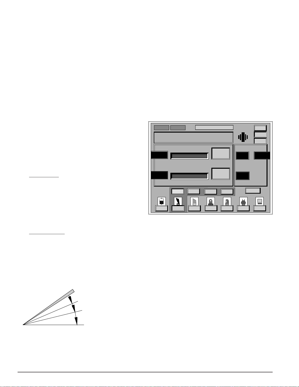
SERIES 20000
AdvanT
ec: V
isco
A.P
. 0%
NeoSoniX
Surgeon
MaxVacac
Lin Flow
AdvanTecec
DR.
ALCON
Def
™*
LEGACY
®
HydroSonics™* (Hydro) Mode (software V3.01 and
below)
Because this mode has only one function, pressing the
Hydro button puts the unit into the HydroSonics™*
mode immediately. The mode display window reads U/S:
Hydro. The HydroSonics™* mode allows use of the auto
HydroSonics™* handpiece, which allows the surgeon to
perform hydrodissection and soften the cataract prior to
phaco-emulsification. No aspiration is provided in the
HydroSonics™* mode.
Injection Rate and U/S Power are the primary parameters
displayed in the HydroSonics™* mode. Pulse Rate is the
secondary parameter. It is displayed in the window
located in the lower right hand portion of the front panel
and is controlled with the arrows to the right of this
window. Following are the allowable injection rates
(pulses/min.) in the HydroSonics™* mode: 60, 70, 80, 90
and 100.
NOTE: When in HydroSonics™* mode the left Reflux
pedal provides pulsed injection only, with no U/S.
• If
Panel Control is selected, pulsed fixed ultrasonic
power is delivered in footpedal position 2 at the preset
or operator set power level maximum limit. The
ultrasonic power maximum limit is initialized to 80%
at power up. In footpedal position 3 fixed ultrasonic
power and pulsed injection are provided. The injection
rate is initialized to 60 pulses/min. at power up.
AdvanTec Mode (software V3.12 and above)
AdvanTec Mode supports the NeoSonix™*, the 375/40,
and the Mackool** 375/40 U/S handpieces. When the
AdvanTec function is operational, irrigation, aspiration,
and ultrasonics are provided by the handpiece. In
addition to these, the NeoSonix™* handpiece provides
mechanical oscillations. The user has the ability to adjust
the aspiration rate, vacuum levels, U/S power and
NeoSonix™* parameters, Amplitude and Threshold (if
applicable) above or below the preset levels at any time
during the surgical procedure via the respective
adjustment buttons or the remote control. The
NeoSonix™* parameters become active when the
NeoSonix™* handpiece is attached, otherwise they are
grayed out.
Not Primed
AdvanT
Max Limit
0
120
Max Limit
Irr
Not Tuned
ec: V
isco
U/S Power
Vac Level
Visco
AdvanT
MaxV
Phaco
DR. ALCON
DR.
U/S
ALCON
mmHg
%
Pulse
Def
A.P
. 0%
NeoSoniX
NeoSoniX
0
Actual
0
Actual
I/A
Burst
Vit
50
Amplitude
NeoSoniX
0
Threshold
Coag
00
%%
%%
Asp Rate
Max Limit
Memory
Custom
Panel
Surgeon
Lin Flow
cc/mincc/min
20
• If
Surgeon Control is selected, ultrasonic power varies
from 0% at the top of footpedal position 2, to the full
preset or operator set power level maximum limit at
the bottom of footpedal position 3. The ultrasonic
power maximum limit is initialized to 80% at power
up. Pulsed injection is added to variable ultrasonic
power in footpedal position 3. The injection rate is
initialized to 60 pulses/min. at power up.
OFF (position 0)
Figure 1-13 FOOTSWITCH FUNCTIONS -
HydroSonics™*
IRRIGATION (position 1)
PULSED U/S (position 2)
PULSED U/S & PULSED INJECTION
(position 3)
Figure 1-14 ADVANTEC VISCO MODE
There are four selectable submodes within AdvanTec
mode: Visco, Phaco, Pulse, and Burst; each reached by
pressing the appropriate area on the display screen or
remote control.
NOTE: If a NeoSonix™*, Mackool**, or 375/40 U/S
handpiece is not connected, or is not connected
properly, a U/S handpiece symbol blinks in the text
window.
U/S power or NeoSonix™* amplitude are increased or
decreased via the front panel in increments of 5% from
minimum of 0% to a maximum of 100%. Ultrasonic
power is controlled by one of two methods: Panel control
or Surgeon control.
All AdvanTec submodes provide irrigation in footpedal
position 1.
1-16 906-2000-501
Page 25
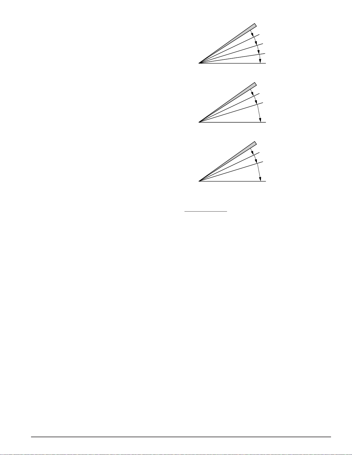
SERIES 20000
IRR / ASP / Ultrasonics
(position 3; U/S power <NeoSoniX threshold)
IRR / ASP / Ultrasonics/NeoSoniX
(position 3; U/S power ≥NeoSoniX threshold)
IRR / Aspiration (position 2)
OFF (position 0)
Irrigation (position 1)
IRR / ASP / Ultrasonics
(position 3; NeoSoniX threshold >U/S power
limit or NeoSonix amplitude = 0)
IRR / Aspiration (position 2)
OFF (position 0)
Irrigation (position 1)
IRR / ASP / NeoSoniX
(position 3; NeoSoniX threshold = 0,
U/S power = 0)
IRR / Aspiration (position 2)
OFF (position 0)
Irrigation (position 1)
™*
LEGACY
®
If the Lin Flow button is not highlighted, footpedal
position 2 provides irrigation and fixed aspiration
according to the flow rate selected. When Lin Flow
button is highlighted, the console will announce "Linear
Flow." When the button is pressed again (Lin Flow not
highlighted), the console will announce "Fixed Flow." If
Lin Flow is highlighted, footpedal position 2 provides
irrigation and aspiration proportional to the displacement
of footpedal throughout position 2. It starts at 0 cc/min at
the top of the position 2 and reaches maximum value as
set on the screen at the bottom of position 2.
Footpedal position 3 provides irrigation, fixed aspiration
flow rate as set on the main screen or on the Custom/
Special Functions/Aspiration screen if defined and
different from the flow rate set on the main screen.
• If U/S Panel Control (including linear or fixed flow
in footpedal position 2) is selected, ultrasound power
will be constant throughout the footpedal position 3
and equal to the power setting as set on the screen.
To increase or decrease power, the arrow buttons are
activated. The default maximum U/S power level
setting is 60% except for AdvanTec Visco submode
where it is 0%.
• If U/S Surgeon Control (including linear or fixed
flow in footpedal position 2) is selected, the
ultrasound power display indicates the maximum
power available. To increase ultrasonic power the
surgeon must further depress the footpedal into
position 3. Power starts at 0% and increases until
power reaches the displayed maximum setting. To
change the maximum available power, activate the
up or down arrow which will raise or lower the
maximum power available. The default maximum
U/S power level setting is 60%, except for AdvanTec
Visco submode where it is 0%.
NeoSonix™* oscillations are activated when the
ultrasound power reaches or exceeds the NeoSonix™*
threshold displayed on the screen. At that point
oscillations are activated according to the NeoSonix™*
amplitude displayed on the screen. There is no
proportional Surgeon control of the NeoSonix™*
amplitude. In footpedal position 1-2 the amplitude
maximum value is displayed. In footpedal position 3 the
actual value of the amplitude is displayed, that is, 0% is
displayed while the ultrasound power is less than the
NeoSonix™* threshold, and the maximum amplitude
value is displayed when the ultrasound power is equal to
or exceeds the threshold.
Figure 1-15 FOOTSWITCH FUNCTIONS - AdvanTec
AdvanTec Visco
The AdvanTec Visco submode is automatically entered
when system power is initially turned ON and the self
test is successfully passed, or when the AdvanTec button
is pressed, “AdvanTec: Visco” is displayed, and the
NeoSonix™* or 375/40 U/S handpiece is activated.
This submode is designed to simplify creation of working
space in the anterior chamber filled with a viscoelastic
material prior to engaging ultrasound. Viscoelastic
material can occlude the aspiration port and/or reduce
wound leakage. Either of the events, and especially a
combination of both, can lead to rapid and significant
increase of temperature in the anterior chamber,
especially at the incision site when ultrasound is
activated. To minimize the possibility of thermal injury
to eye tissues it is therefore recommended to partially
aspirate viscoelastic material from the anterior chamber.
The AdvanTec Visco submode contains default values of
120 mm Hg vacuum limit, and 0% of ultrasound power
and NeoSonix™* amplitude. If a user finds it helpful to
add a small amount of ultrasound or NeoSonix™* action
to facilitate partial removal of viscoelastic, the ultrasound
and/or NeoSonix™* will be available pulsed at 8 pulses
per second, 25% time on, 75% time off. Maximum
ultrasound power is limited to 50% in this submode.
906-2000-501 1-17
Page 26

SERIES 20000
™*
LEGACY
®
U/S Power Level and Vac Level are the primary
parameters displayed; Aspiration Flow Rate is the
secondary parameter displayed. If NeoSonix™*
handpiece is connected, NeoSonix™* parameters,
Amplitude, and Threshold are displayed as an additional
secondary parameters pair.
AdvanTec Phaco
Press the AdvanTec button, then select Phaco submode.
AdvanTec: Phaco is displayed. This submode provides
continuous ultrasound and NeoSonix™* oscillations, if
applicable.
U/S Power Level and Vac Level are the primary
parameters displayed, Aspiration Flow Rate is the
secondary parameter displayed. If NeoSonix™*
handpiece is connected, NeoSonix™* parameters,
Amplitude, and Threshold are displayed as an additional
pair of secondary parameters.
AdvanTec Pulse
Press the AdvanTec button, then select Pulse submode.
AdvanTec: Pulse is displayed. When operating in this
mode, U/S power and NeoSonix™* oscillations are
turned on and off in a 50% duty cycle (50% on time, 50%
off time) with a frequency determined by the pulse rate
setting.
U/S Power Level and Vac Level are the primary
parameters displayed, Aspiration Flow Rate and Pulse
Rate are the secondary parameters displayed. If
NeoSonix™* handpiece is connected, NeoSonix™*
parameters, Amplitude, and Threshold are displayed as
an additional secondary parameters pair.
AdvanTec Burst
Press the AdvanTec button, then select AdvanTec Burst
submode on the screen. AdvanTec Burst is displayed.
The AdvanTec Burst function allows bursts of ultrasound
and/or NeoSonix™* oscillations, of preset or operator set
duration, to occur either singly, or with a linearlycontrolled frequency.
AdvanTec Burst differs from other AdvanTec submodes
in that the U/S power is fixed at the preset or operator set
limit, throughout footpedal position 3. This is true for
both Panel and Surgeon control in AdvanTec Burst.
• AdvanTec Burst Panel Control provides a single
burst of ultrasonic power and/or NeoSonix™*
oscillations upon entrance to footpedal position 3.
NeoSonix™* oscillations will be delivered if the
NeoSonix™* handpiece is used and the ultrasound
power setting is equal to or exceeds the threshold.
- The duration of this burst is determined by the
preset or operator set limit.
- When a single burst is complete, the user must
lift the footpedal and re-enter position 3 to get
each additional burst.
• AdvanTec Burst Surgeon Control provides repeated
bursts of ultrasonic power and/or NeoSonix™*
oscillations in footpedal position 3.
- The duration of each burst is determined by the
preset or operator set limit.
- The time between each burst, during which no U/S
power or NeoSonix™* oscillations are applied,
varies linearly from the 2.5 second maximum at the
top of footpedal position 3, to the 0 second
(continuous) minimum at the bottom of position 3.
U/S Power Level and Vac Level are the primary
parameters displayed, Aspiration Flow Rate and Burst
Width are the secondary parameters displayed. If a
NeoSonix™* handpiece is connected, then NeoSonix™*
parameters, Amplitude, and Threshold are displayed as
an additional secondary parameters pair.
1-18 906-2000-501
Page 27
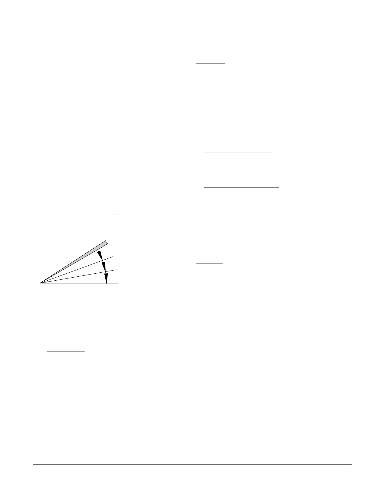
SERIES 20000
™*
LEGACY
®
Ultrasound (U/S) Mode
There are four selectable sub-modes within U/S Mode:
Phaco, Pulse, BiModal, and Burst; each reached by
pressing the appropriate area on the display screen or
remote control.
NOTE: The NeoSonix™* handpiece is for systems
with software V3.12 and above only. It will not be
recognized on systems with lower versions of
software.
This mode is designed to use either the 375/40 ultrasonic
or NeoSonix™* handpieces. Only ultrasound vibrations
will be produced by the NeoSonix™* handpiece in this
mode, so operation of the NeoSonix™* handpiece is
largely identical to that of the 375/40 ultrasonic
handpiece. Therefore, all statements made regarding
operation of the 375/40 U/S handpiece in the U/S mode
are also applicable to the operation of the NeoSonix™*
handpiece in the U/S mode.
NOTE: If a 375/40 U/S, Mackool**, or NeoSonix™*
handpiece is not connected, or is not connected
properly, a U/S handpiece symbol blinks in the text
window.
OFF (position 0)
IRRIGATION (position 1)
or down arrow which will raise or lower the maximum
power available. The default maximum U/S power
level setting is 60%.
U/S Phaco
This is the default function within the U/S Mode. When
the U/S button is pressed, “U/S:Phaco” is displayed and
the 375/40 U/S handpiece is activated. When the U/S
function is operational, irrigation, aspiration, and
ultrasonics are provided by the 375/40 U/S handpiece.
The user has the ability to adjust the aspiration rate,
vacuum levels, and U/S power above or below the preset
levels at any time during the surgical procedure via the
respective adjustment buttons or the remote control.
• U/S Phaco Panel Control provides irrigation
(footpedal position 1), irrigation/aspiration (footpedal
position 2), and irrigation/aspiration/fixed ultrasonics
simultaneously (footpedal position 3).
•
U/S Phaco Surgeon Control allows the user to linearly
control the ultrasonic power via the footpedal in
position 3 from 0% power up to whatever has been set
as the maximum ultrasonic power on the console.
U/S Power Level and Vac Level are the primary
parameters displayed; Aspiration Flow Rate is the
secondary parameter displayed.
IRR/ASPIRATION (position 2)
IRR/ASP/ULTRASONICS (position 3)
Figure 1-16 FOOTSWITCH FUNCTIONS - U/S
U/S power is increased or decreased via the front panel in
increments of 5% to a maximum of 100%. Ultrasonic
power is controlled by one of two methods: either Panel
control or Surgeon control.
• If Panel Control is selected, the power setting is
displayed on the ultrasonic power display. To increase
or decrease power, the arrow buttons are activated.
Ultrasonic power is initialized to 60% at power up.
The selected power is fully activated in footpedal
position 3.
• If
Surgeon Control (including Srg Asp and Srg Vac) is
selected, the ultrasonic power display indicates the
maximum power available. To increase ultrasonic
power the surgeon must further depress the footpedal
into position 3. Power starts at 0% and increases until
power reaches the displayed maximum setting. To
change the maximum available power, activate the up
U/S Pulse
Press the U/S button, then select Pulse mode. U/S: Pulse
is displayed. When operating in this function, U/S power
is turned on and off on a 50% duty cycle, with a
freequency determined by the pulse rate setting.
• U/S Pulse Panel Control provides irrigation in
footpedal position 1, irrigation and aspiration in
footpedal position 2, and simultaneous irrigation,
aspiration, and fixed pulsed ultrasonics in footpedal
position 3. The aspiration rate, vacuum limit, U/S
power, and pulse rate are all preset at default values,
but can be increased or decreased before or during the
procedure via the up and down arrows adjacent to
their respective windows on the front panel or remote
control.
•
U/S Pulse Surgeon Control performs the same as
Panel control plus it provides pulsed U/S power
linearly via the footswitch from 0% up to the
maximum preset or operator set limit.
U/S Power and Vac Level are the primary parameters
displayed; Aspiration Flow Rate and Pulse Rate are the
secondary parameters displayed.
906-2000-501 1-19
Page 28

SERIES 20000
™*
LEGACY
®
U/S BiModal
Press the U/S button, then select U/S BiModal mode on
the screen. U/S: BiModal is displayed. The U/S BiModal
function allows linear control of aspiration rate or
vacuum limit in footpedal position 2, plus linear control
of U/S power in position 3.
•
U/S BiModal SrgAsp Control provides irrigation in
footpedal position 1, irrigation and linearly controlled
aspiration in footpedal position 2, and simultaneous
irrigation, fixed aspiration, and linearly controlled U/S
power in footpedal position 3.
- In footpedal position 2, the aspiration rate starts
at 1 cc/min at the top of the position, and reaches
the full preset or operator set flow rate at the end
of position 2.
- In footpedal position 3, the full aspiration flow
rate is maintained, while U/S power varies from
0% at the top, to the maximum preset or operator
set limit at the bottom of the position.
U/S BiModal SrgVac Control is functionally identical
•
to U/S BiModal SrgAsp control mode, except that:
- The duration of this burst is determined by the
preset or operator set limit.
- When a single burst is complete, the user must
lift the footpedal and reenter position 3 in order
to get each additional burst.
U/S Burst Surgeon Control provides irrigation
•
(footpedal position 1), irrigation/aspiration (footpedal
position 2), and repeated bursts of ultrasonic power
(footpedal position 3).
- The duration of each burst is determined by the
preset or operator set limit.
- The time between each burst, during which no
U/S power is applied, varies linearly from the 2.5
second maximum at the top of footpedal position
3, to the 0 second (continuous U/S) minimum at
the bottom of position 3.
U/S Power and Vac Level are the primary parameters
displayed; Aspiration Flow Rate and Burst Width are the
secondary parameters displayed.
- In footpedal position 2, the vacuum limit is
varied linearly from 1 mmHg at the top of the
position to the preset or operator set limit at the
bottom of position 2.
- The aspiration flow rate is fixed, at the preset or
operator set limit, in both footpedal position 2
and 3.
U/S Power and Vac Level are the primary parameters
displayed; Aspiration Flow rate is the secondary
parameter displayed.
U/S Burst
Press the U/S button, then select U/S Burst mode on the
screen. U/S: Burst is displayed. The U/S Burst function
allows bursts of U/S power, of preset or operator set
duration, to occur either singly, or with a linearly
controlled frequency.
U/S Burst differs from other U/S submodes in that U/S
power is fixed, at the preset or operator set limit,
throughout footpedal position 3. This is true for both
Panel and Surgeon control in U/S Burst.
• U/S Burst Panel Control provides irrigation (footpedal
position 1), irrigation/aspiration (footpedal position 2),
and a single burst of ultrasonic power upon entrance
to footpedal position 3.
Irrigation/Aspiration (I/A) Mode
There are three selectable sub modes within the
Irrigation/Aspiration mode: Minimum (I/A Min),
Maximum (I/A Max), and Capsule Vacuum (Cap Vac).
Each of the selectable functions is reached by pressing
the appropriate button. The I/A mode provides
gravity-feed irrigation and/or simultaneous peristaltic
aspiration. In any of the sub modes under Panel Control,
the operator can adjust the preset aspiration and vacuum
limits using the adjustment control buttons on the control
panel.
OFF (position 0)
IRRIGATION (position 1)
IRR/ASPIRATION (position 2)
IRR/ASPIRATION (position 3)
Figure 1-17 FOOTSWITCH FUNCTIONS - I/A
I/A Max
Press the I/A button then select I/A Max on the screen or
the remote. I/A: Max is displayed. I/A Max provides
irrigation (footpedal position 1) and simultaneous
irrigation and aspiration (footpedal positions 2 and 3).
The preset vacuum level for I/A Max is 500+ mmHg
(unlimited), and the adjustable range is 0 to 500+mmHg
(unlimited).
1-20 906-2000-501
Page 29

SERIES 20000
™*
LEGACY
®
• I/A Max Panel Control - I/A Max Panel provides
irrigation in footpedal position 1 and simultaneous
irrigation and aspiration in footpedal positions 2 and
3.
•
I/A Max Surgeon Control
- Surgeon (Surg) Asp - identical to Panel control
except footpedal positions 2 and 3 allow linear
control of aspiration flow rate with fixed vacuum
limits.
- Surgeon (Surg) Vac - identical to Panel control
except footpedal positions 2 and 3 allow linear
control of vacuum limits with fixed aspiration
flow rate.
Asp Rate and Vac Level are the primary parameters
displayed.
I/A Min
Press the I/A button then select I/A Min on the screen or
the remote. I/A: Min is displayed.
• I/A Min Panel Control - for a low preset vacuum limit
of 66 mmHg, and an adjustable range of 0 to 500+
mmHg. The levels manually set by the operator can be
easily increased or decreased before or during
operation. I/A Min provides irrigation in footpedal
position 1 and simultaneous irrigation and aspiration
in footpedal positions 2 and 3.
•
I/A Min Surgeon Control
- Surgeon (Surg) Asp - identical to Panel Control
except footpedal positions 2 and 3 allow linear
control of aspiration flow rate with fixed
vacuum limits.
- Surgeon (Surg) Vac - identical to Panel Control
except footpedal positions 2 and 3 allow linear
control of vacuum limits with fixed aspiration
flow rate.
Cap Vac
Press the I/A button, then select the CapVac mode on the
screen or the remote control. I/A CapVac is displayed.
CapVac provides irrigation and low aspiration rate and
vacuum limit, allowing the surgeon to polish the surface
of the posterior capsule following the emulsification and
removal of the cataractous tissue. The preset vacuum
limit is 5mmHg.
Asp Rate and Vac Level are the primary parameters.
Only Panel Control is enabled in the CapVac function.
Kelman® Steerable I/A System Option
The Kelman® Steerable I/A system consists of a flexible,
steerable irrigation/aspiration tip with an accompanying
handpiece and drive mechanism. The Steerable I/A
system is used in I/A mode to remove cortical material
via aspiration while maintaining chamber pressure with
irrigation.
The system is used with the infusion sleeve provided in
the Legacy® pak. This system provides aspiration and
irrigation and the ability to easily, smoothly, and
continually adjust the tip in the eye from a straight
position to a fully bent position. The ability to steer the
tip provides the Surgeon with greater access to all
cortical material in the eye. The operator has the ability
to steer the tip via the footswitch, and the distal end of
the tip will remain in that position until changed by the
operator via the footswitch.
The Kelman® Steerable I/A system is an option and must
be installed in the Legacy® console. The Steerable
I/A system is limited to altitudes up to 6,000 feet (1,828
meters). Once installed, the system must be selected in
the Custom mode (see Custom Mode). All functions of
the Irrigation/Aspiration (I/A) mode are available when
the Steerable I/A system is installed and selected.
Asp Rate and Vac Level are the primary parameters
displayed.
between straight and fully bent by pressing the right and
left vertical switches on the footswitch. The left vertical
switch increases the bend of the tip, while the right
vertical switch reduces the bend.
906-2000-501 1-21
The Kelman® Steerable I/A tip is adjusted to any position
Page 30
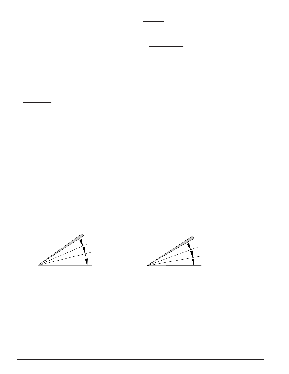
SERIES 20000
™*
LEGACY
®
Vitrectomy (Vit) Mode
There are two selectable sub modes within the
Vitrectomy (Vit) mode: ATIOP and I/A Cutter. Each is
reached by pressing the appropriate mode on the screen,
and each utilizes the pneumatically operated ATIOP
handpiece. The cutting rate for both sub modes is
adjustable from 0 to 400 cuts per minute.
ATIOP
This is the default for the VIT mode. Press the VIT mode
on the screen or the remote and Vit: ATIOP is displayed.
•
ATIOP Panel - Irrigation is provided in footpedal
position 1; irrigation and guillotine-motion cutting in
position 2; and irrigation, cutting, and aspiration in
position 3. The operator can adjust the preset
aspiration and vacuum limits using the adjustment
control buttons on the control panel or on the remote
control.
•
ATIOP Surgeon
- Surgeon (Surg) Asp - identical to Panel Control
except footpedal positions 3 allows linear control
of aspiration flow rate with fixed vacuum limits.
- Surgeon (Surg) Vac - identical to Panel Control
except footpedal positions 3 allows linear control
of vacuum limits with fixed aspiration flow rate.
Asp Rate and Vac Level are the primary parameters
displayed. Cutting rate is the secondary parameter.
I/A Cutter
Press VIT mode. Select the I/A Cutter mode on the
screen or remote and “Vit: I/A Cutter” is displayed.
• I/A Cutter Panel - Irrigation is provided in footpedal
position 1; irrigation and aspiration in position 2; and
irrigation, aspiration, and cutting in position 3.
•
I/A Cutter Surgeon
- Surgeon (Surg) Asp - identical to Panel Control
except footpedal positions 2 and 3 allow linear
control of aspiration flow rate with fixed vacuum
limits.
- Surgeon (Surg) Vac - identical to Panel Control
except footpedal positions 2 and 3 allow linear
control of vacuum limits with fixed aspiration
flow rate.
Asp Rate and Vac Level are the primary parameters
displayed. Cutting rate is the secondary parameter.
ATIOP
OFF (position 0)
IRRIGATION (position 1)
IRR/CUTTING (position 2)
IRR/ASP/CUTTING (position 3)
I/A CUTTER
OFF (position 0)
IRRIGATION (position 1)
IRR/ASPIRATION (position 2)
IRR/ASP/CUTTING (position 3)
Figure 1-18 FOOTSWITCH FUNCTIONS - VITRECTOMY
1-22 906-2000-501
Page 31

SERIES 20000
Panel
DR.
ALCON
Def
Not Primed
Not
uned
375-40 KHz
™*
LEGACY
®
Coagulation (Coag) Mode
Press the COAG button on the front panel to initiate the
Coagulation mode. Coagulation is displayed, and in
footpedal position 2 an audible tone is initialized. As in
all other modes, settings in COAG are retained in
memory so that when
re-entering the Coagulation Mode,
the previous settings are displayed.
The displayed parameter is the percentage of the
maximum available coagulation voltage. The default
percentage is 30%; variation from this default level is
accomplished by the up and down arrows. The
Coagulation mode provides approximately 340 Khz
frequency bipolar coagulation to drive Alcon brush and
forceps up to the preset limit upon activation of the
Footswitch. Voltage level setting on the front panel
ranges from 10% to 100%.
Coagulation is controlled by either Panel or Surgeon
control.
• COAG - Panel Control - provides bipolar coagulation
at the preset limit upon activation of the Footpedal in
positions 2 and 3.
•
COAG - Surgeon Control - The applied voltage is
varied linearly from 10% to the preset limit. Voltage
variation begins at Footpedal position 2 and ends at
the completion of travel in footpedal position 3.
Coagulation During Priming
Panel controlled coagulation is active in the Test mode
on any screen during Priming and Cleaning of the
system. It is not active during U/S or HydroSonics
™*
handpiece tuning. Coagulation during Test mode is only
available with Panel control. The percentage of the
maximum Coagulation voltage will be displayed on the
sidebar of the screen and may be increased or decreased
by adjusting the corresponding arrow keys. These new
values will be retained when Coagulation Panel mode is
selected again.
If you normally use surgeon controlled Coagulation, you
should store both the panel controlled and the surgeon
controlled Coagulation screens in the Custom mode.
Not Primed
Not
Tuned
StdCas
Priming is in progress
FILL
Prime
Irr
FILL
Phaco
AdvanTec
DR.
Pulse
U/S
ALCON
TUNETUNE
Bimodal
I/A
Def
375-40 KHz
CLEAN
CLEAN
STOP
STOP
Burst
Vit
Panel
0
Coag Volt
30 %
Max Limit
Coagulation disabled
during tuning
Coag
Custom
WARNING!
Do not use the coagulation function on patients
with pacemakers. If electrosurgery is used on
patients with implanted cardiac pacemakers or
pacemaker electrodes, be aware that irreparable
damage to the pacemaker and its function may
occur and lead to ventricular fibrillation.
CAUTION
The STTL is not protected against the effects of
defibrillator discharge.
Figure 1-19 FOOTSWITCH FUNCTIONS - COAG
OFF (position 0)
STANDBY (position 1)
POWER (position 2)
POWER (position 3)
Figure 1-20 PRIMING IS IN PROGRESS
(software V3.12 shown)
906-2000-501 1-23
Page 32

Program
FITZGERALD
FITZGERALD
Custom: Program
Def
CUSTOM MODE for software versions 3.01 and below
SERIES 20000
™*
LEGACY
®
The Custom menu consists of six modes and four special
functions which provide the user with the ability to
modify system settings and to access system
programmability. The modes are:
• Program: new surgeon entry, programming of
operational preferences.
• Sound: audio levels for coagulation, vacuum level,
U/S occlusion, and aspiration occlusion.
• Voice: audio level as well as ON and OFF selection.
• Language: English (other languages may be available
in the future).
• Footswitch: Footswitch control of continuous
irrigation, footswitch vertical control (IV pole or
Steerable I/A), detent position, and stiffness.
• Remote: channel A/B/C/D select.
The special function modes are IV Pole, Aspiration,
Patient Eye Level (PEL), and Disk.
• IV Pole sets the height of the irrigation bottle in each
of the sub modes.
• Aspiration sets the aspiration flow rate in footpedal
position 3 in each of the U/S submodes.
• PEL provides an offset to the IV Pole display to
accommodate low patient eye levels and/or the use of
the IV pole extender.
• Disk allows backup and restoration of doctor
memories, using 3.5" disks.
To return to the Mode screen, press the Exit button.
Custom - Program Mode
Program is the default mode after pressing the Custom
key. This mode allows system operational parameters to
be programmed, stored, and retrieved. Previously saved
parameters are saved under a doctor name & memory
number. The up and down arrows scroll the doctor list up
and down a page at a time. There are four pages of six
names each for a total of 24 doctor names. Each name
has four memory settings (Store memory) associated with
it.
For the purposes of this section, doctor’s memory will
refer to the doctor’s name, and the memory setting will
refer to the doctor’s memory number. Each of these
definitions is used interchangeably. Memory settings are
located in a pop-up screen in the main screen.
• Add a Doctor
1. Press Custom.
2. Press Add in Edit Doctor Box.
3. Type Doctor name on the displayed keyboard (field
is limited to 18 characters). When required, the
Backspace key deletes a single character to the left of
the cursor. The Cancel key returns to the Program
mode without saving.
4. Press Store. The doctor’s name is now the selected or
active name for the Program screen (right side of
screen).
5. Press Exit to return to Main Menu screen and to
customize the program.
• Erase a Doctor
Custom: Program
Edit Doctor
Add
Store Memory
1234
Special Functions
IV Pole Asp P.E.L. Disk
Program
Sound
Erase
Voice
FITZGERALD
ANDERSON
FITZGERALD
FRANKLIN
MARTINEZ
NGUYEN
SCHMIDT
Lang
FootSw Remote Exit
Def
Figure 1-21 CUSTOM: PROGRAM (V3.01 and below)
1-24 906-2000-501
1. Press Custom.
2. Select Doctor to be erased from the right side of the
screen.
3. Press Exit.
4. Enter Custom mode again.
5. Press Erase in Edit Doctor box.
6. Press Yes to confirm.
7. Press Exit to return to Main menu.
Page 33

SERIES 20000
Irr Footsw
cm.
Special Functions: IV Pole
Exit
Special Functions: Special Functions: AspirationAspiration
Select Desired Mode and Use + and –
Keys to Adjust Aspiration Rate Values.
Footsw Position 3
+
–
Mode
U/S PhacoU/S Phaco
U/S Pulse
U/S BiModal
U/S Burst
Aspiration Rate
cc/mincc/min
cc/mincc/min
cc/mincc/min
cc/mincc/min
™*
LEGACY
®
CUSTOM MODE for software versions 3.01 and below
• Doctor Programming
1. Press Custom.
2. Select Doctor.
3. Press Exit to return to the Main Menu screen.
4. Press each mode that programming is desired for and
enter specific parameters, using the up and down
arrows.
NOTE: Saving Surgeon Controls into Memory - The
memory functions will save each control screen
separately. The last screen saved will be the first one
displayed in memory for each mode; thus, if the
doctor prefers Surg Asp in l/A Max, program the
Surg Asp screen last, before you save in Memory 1.
When Memory 1 is pulled up, Surg Asp will be the
first control mode displayed in l/A Max.
5. After all mode parameters have been set, press
Custom.
6. Press IV Pole button in the Special Functions box to
customize bottle height for individual modes. The
following screen will be displayed:
7. Select the sub mode to be set in the IV Pole sub
menu.
8. Adjust the setting by pressing the + or - boxes on the
screen or any of the up and down arrows (except
those for the IV bottle height) on the front panel.
9. Repeat steps 5 and 6 for each mode/sub mode
desired.
10. Press Exit to return to the Program screen.
NOTE: A blank value for bottle height means
“unprogrammed.” The pole will not move to a new
height when entering the given mode; it remains at
the previous set height (default 65 cm). If the IV pole
cannot reach the programmed height setting, the
bottle height display will blink.
11. Press Aspiration button in the Special Function box
(to customize Aspiration flow rate(s) in the U/S
modes). This allows the surgeon to use two different
aspiration flow rates for foot positions 2 and 3. The
following screen will be displayed:
NOTE: Flow rate in position 3 will not be displayed
on front panel until footpedal is in position 3.
12. Select the sub mode to be set in the Aspiration sub
menu.
13. Adjust the setting by pressing the + or - boxes on the
screen or any of the up and down arrows (except
those for the IV bottle height) on the front panel.
14. Repeat steps 12 and 13 for each mode/sub mode
desired.
15. Press Exit to return to the Program screen.
16. Press one of the four Store Memory buttons to store
all of the above settings. These settings will be used
by the unit until the programming is changed.
17. Press Yes or No to confirm memory storage.
NOTE: Each doctor has the option of four
programmed memory settings available through
Store Memory.
18. Press Exit to return to the Main Menu screen.
NOTE: A blank value for cc/min means
“un-programmed”; ASP in position 3 will be the same
as in position 2.
Special Functions: IV Pole
Mode Bottle Height
Irr Footsw
Irr Freeflow
I/A Min
I/A Max
I/A Cap Vac
U/S Burst
Figure 1-22 SPECIAL IV POLE SETUP
(V3.01 and below)
cm.
cm.
cm.
cm.
cm.
cm.
906-2000-501 1-25
Mode Bottle Height
+
U/S Phaco
U/S Pulse
U/S BiModal
Vit ATIOP
Hydro
–
Vit I/A Cutter
cm.
cm.
cm.
cm.
cm.
cm.
Exit
Figure 1-23 SPECIAL FUNCTIONS: ASPIRATION
(V3.01 and below)
Page 34

CUSTOM MODE for software versions 3.01 and below
SERIES 20000
™*
LEGACY
®
• Access Pre-Programmed Memory Settings
1. Press Custom.
2. Select the programmed doctor’s name.
3. Press Exit.
4. Press Memory button on the right side of the
Main Menu screen.
5. Select desired programmed memory setting (1, 2,
3, or 4). If no memory settings are selected, the
default setting will appear.
• Reprogram Memories
Memories should not be reprogrammed during a case.
Program and Custom sub modes changes should be
made in each memory setting individually to prevent
accidental erasure.
1. Enter Custom screen and select the desired preprogrammed doctor’s name to copy
from.
2. Exit to select the exact Memory Setting (1, 2, 3,
or 4) to copy
from in the pop-up Memory screen.
3. Re-enter Custom mode (copy from doctor’s
name and memory number should be displayed
at the top of the screen in light blue).
4. Make the appropriate changes to the program and
custom sub modes.
5. Enter the Custom mode.
6. Select the same Memory setting to store to.
7. Confirm by pressing Yes.
• Copy Memories
Memories can be copied from one doctor to another.
This procedure will assume the destination Doctor’s
name (copy to) has been stored in memory.
1. Enter Custom screen and select the desired preprogrammed doctor’s name to copy
from.
2. Exit to select the exact Memory Setting (1, 2, 3,
or 4) to copy
from in the pop-up Memory screen.
3. Re-enter Custom mode (copy from doctor’s
name and memory number should be displayed
at the top of the screen in light blue).
4. Select Doctor to copy
to (the copy to doctor’s
name will now be highlighted in green, as well as
the memory settings and the exit key).
5. Select Memory Setting (1, 2, 3, or 4) to store
6. Confirm by depressing Yes.
7. New Doctor’s Name and Memory Number should
be displayed in the upper right hand column with
the updated information. Exiting the Custom mode
will bring up the newly stored program.
to.
• Saving and Restoring Doctor Memories
The system allows the user to back up all memories
onto a formatted 3.5” disk, inserted into the slot found
on the Rear Connector Panel. Once backed up either a
single Doctor, or all Doctor Memories, may be
restored.
NOTE: Restoring all Doctors at once erases and
overwrites any Doctor Memories residing on the
system.
1. Enter the Custom Mode screen and press the
“Disk” button in the Special Functions box.
2. Insert a formatted 3.5” disk into the floppy drive
slot, located on the Rear Connector Panel.
To back up all Doctor Memories press the “All”
3.
button in the Backup Doctors To Diskette box.
Press the “Yes” button in the confirmation
window in the upper left region of the screen.
To restore a single Doctor’s Memory (all
4.
memories belonging to selected Doctor name)
press the “List Doctors On Diskette” button in
the upper right area of the screen. Press the
desired Doctor name button in the list to select a
Doctor. Press the “Selected” button in the
Restore Doctors From Diskette box, then press
the “Yes” button in the confirmation window.
To restore all Doctor Memories press the “All”
5.
button in the Restore Doctors From Diskette box,
then press the “Yes” button in the confirmation
window.
• Setting a Patient Eye Level Adjustment
The system supports a Patient Eye Level offset
adjustment which allows the user to perform surgery
on eyes that are positioned below the cassette. This
offset value is a system-wide value, and is recovered
each time the user turns on system power. When a
non-zero offset value is in effect, the letters "PEL"
will be displayed in the text window of all operating
mode screens.
NOTE: The Patient Eye Level setting is global. If
changed, it will affect previously stored values for IV
bottle height.
1. Enter the Custom Mode screen and press the
"P.E.L." button in the Special Functions box.
2. Adjust the setting by pressing the + or – boxes on
the screen or any of the up and down arrows
(except those for the IV bottle height) on the
front panel.
1-26 906-2000-501
Page 35

SERIES 20000
Sound
Custom: Sound
ON
ON
™*
LEGACY
®
CUSTOM MODE for software versions 3.01 and below
• For using the IV Pole Extender.
1. Enter the Custom Mode screen and press the
"P.E.L." button in the Special Functions box.
2. Adjust the setting to -32 cm by pressing the + or
– boxes on the screen or any of the up and down
arrows (except those for the IV bottle height) on
the front panel.
3. For further information, such as how to combine
this with patient eye level variations, refer to the
DFU that was supplied with the IV Pole
Extender.
NOTE: A blank value for the Patient Eye Level
means "unprogrammed."
Custom - Sound Mode
In this mode the Sound key highlights and Custom:
Sound appears in the title area.
Custom Sound mode provides control over sound tone
generation. The individual volume selection, and in some
cases On/Off control, is provided. Controls are activated
via touch keys. The volume of aspiration occlusion, U/S
occlusion, Vacuum, and Coagulation tones are controlled
individually. The + and – keys provide linear control over
tone values, as reflected by the corresponding volume
meters. The On/Off controls toggle the tone generation
status for Aspiration Occlusion and Vacuum tones; U/S
Occlusion and Coagulation tones cannot be turned off
completely.
Custom - Voice Mode
In this mode, the Voice menu key is highlighted and
Custom: Voice is displayed in the title area.
The Custom Voice mode provides control of the system
voice output. A toggle On/Off control and a linear
volume control are provided. Controls are activated by
the touch keys. Arrow keys will scroll volume level.
Custom - Language Mode
In this mode, the Lang menu key will be highlighted and
Custom: Language will be displayed in the title area (for
future expansion).
The Custom Language mode will allow selection of the
system language. System Voice will prompt the user, and
screen text will provide the selected language. The
selection will be a multiple choice toggle activated via
the touch keys.
Custom - Footswitch Mode
In this mode the FootSw menu key is highlighted and
Custom: Footswitch is displayed in the title area.
The Series 20000
™*
and Accurus®/Legacy® footswitches
offer programmable footpedal detent placement. The
Custom Footswitch mode allows the footpedal travel
between detents to be moved by selecting the Normal,
I/A, or Phaco keys. The footpedal is defaulted to Normal.
(Note: programmable detents are not available when
using the ATFS-Legacy® footswitch.) Footpedal detent
stiffness can be selected as Hard, Medium, and Soft
(default is Medium). The percent of footpedal travel in
each enhanced mode is listed in the table below:
Table 1-3 FOOTPEDAL TRAVEL IN ENHANCED
MODES (V3.01 and below)
Footpedal Travel Normal I/A Phaco
Between Detents
Custom: Sound
1 to 2 16% 16% 13%
0 to 1 5% 5% 5%
–
Audio Level
+
–
Audio Level
+
2 to 3 35% 50% 25%
ON
Asp Occlusion
OFF
ON
Vacuum
OFF
3 to base 44% 29% 57%
–
U/S Occlusion
Audio Level
+
–
Audio Level
Coagulation
+
Continuous irrigation is available in all three custom
footswitch detent modes; it defaults to DISABLE. The
function allows the right side pedal to toggle the
irrigation valve ON and OFF.
Program
Sound
Voice
Lang
Figure 1-24 CUSTOM: SOUND (V3.01 and below)
906-2000-501 1-27
FootSw
Remote Exit
Page 36

FootSw
CUSTOM MODE for software versions 3.01 and below
SERIES 20000
™*
LEGACY
®
Custom: Footswitch
Footswitch
Vertical
Control
I/V Pole
Steer I/A
None
Program
Cont. Irr.
Enable
Disable
Sound Remote Exit
Voice
Detent Range
Lang
Normal
I/A
Phaco
FootSw
Stiffness
Hard
Medium
Soft
Figure 1-25 CUSTOM: FOOTSWITCH
(V3.01 and below)
Footswitch control of certain functions, using the left and
right vertical buttons, may be selected or disabled. If
"None" is selected, the vertical buttons have no effect.
Selecting "IV Pole" allows the user to increase or
decrease the IV Pole height, using the right and left
vertical buttons, respectively. If the Steerable I/A
hardware is present on the system, the "Steerable I/A"
button appears on the Custom Footswitch screen. If
selected, this allows the Steerable I/A handpiece tip to
increasingly bend, using the right vertical button, or
straighten, using the left.
These footpedal adjustments may be stored into memory:
Detent Position, Detent Stiffness, and Continuous
Irrigation. The three variables, however, are only
available once per doctor’s memory (i.e., Phaco - soft,
Continuous Irrigation-On could be saved in Dr Alcon 1;
and I/A medium, Continuous Irrigation-Off saved in Dr
Alcon 2). You
cannot save more than one set of variables
in one memory. The set of variables saved will be global
for that entire memory selection.
Custom - Remote Mode
In this mode, the Remote menu key is highlighted and
Custom: Remote is displayed in the title area.
The Custom Remote mode allows the selection of four
remote receive codes: A, B, C, & D. This selection must
correspond to the channel selection on the remote
control. The channel is a toggle selection activated via
the touch screen. No additional steps are needed once the
remote channel is set.
The remote control must be switched to the appropriate
channel. Switch is located near the battery compartment
(see Figure 1-10). "A" channel is the default channel. If
the proper channel is not programmed on the front panel,
the remote control will not function and all changes will
have to be made via the front panel.
1-28 906-2000-501
Page 37

SERIES 20000
™*
LEGACY
®
CUSTOM MODE for software versions 3.12 and above
The Custom menu consists of six Modes and six Special
Functions which provide the user with the ability to
modify system settings and to access system
programmability. The modes are:
• Program: Programming new surgeon entry and
operational preferences, and access to Special
Functions.
Sound: audio levels for coagulation, vacuum level,
•
U/S occlusion and pre-occlusion, U/S Tone, and
aspiration occlusion and pre-occlusion.
Voice: audio level as well as ON and OFF selection.
•
Language: English (other languages may be available
•
as options).
Footswitch: Footswitch control of switching between
•
memories, modes and/or submodes, continuous
irrigation, footswitch vertical control (IV pole or
Steerable I/A), detent position, and stiffness.
Remote: channel A/B/C/D select.
•
Modes and Submodes
The Custom/Program/Special Functions features are IV
Pole, Aspiration, Occlusion, Disk, Metrics, and Patient
Eye Level (PEL).
•
IV Pole sets the height of the irrigation bottle in each
of the sub modes.
Aspiration sets the aspiration flow rate in footpedal
•
position 3 in each of the AdvanTec and U/S
submodes.
Occlusion screen defines U/S power and
•
NeoSonix™* amplitude automatic reduction as
vacuum reaches pre-occlusion or occlusion values.
Pre-occlusion value is equal to approximately 90% of
the occlusion (vacuum limit) value. This power
reduction takes effect only in those submodes where
continuous ultrasound can be used: AdvanTec Phaco,
U/S Phaco and U/S BiModal.
Disk allows backup and restoration of doctor
•
memories, using 3.5" disks.
Legacy
Edit
Doctor
• Add
• Erase
Tones for:
• Aspiration
Occlusion
• U/S
Occlusion
• Aspiration
Pre-Occlusion
• U/S
Pre-Occlusion
• U/S Power
• Vacuum
• Coagulation
Store
Memory
• 1
• 2
• 3
• 4
• All
Custom Mode
VoiceSoundProgram
Control of:
• On/Off
• Volume
Special
Functions
• IV Pole
• Aspiration
• Occlusion
• Disk
• Metrics
• P.E.L.
Language:
• English
• Français
• Español
• Deutsch
• Italiano
• Português
• Japanese
Programming of:
• Right Heel
and Remote
•
Vertical Control
• Continuous
Irrigation
• Detent Range
• Stiffness
RemoteFootswLang
Select:
• Channel A
• Channel B
• Channel C
• Channel D
Figure 1-26 CUSTOM MODE (V3.12 and above)
906-2000-501 1-29
Page 38

CUSTOM MODE for software versions 3.12 and above
Def
Custom: Program
Program
Special Functions: Metrics
SERIES 20000
™*
LEGACY
®
Custom: Program
Edit Doctor
Add
Store Memory
1
2
3
Special Functions
IV Pole Occl
Disk
Program
Asp
Metrics
Sound Remote Exit
Erase
4
P.E.L.
V
O
I
C
E
FITZGERALD
ANDERSON
FITZGERALD
Lang
FRANKLIN
MARTINEZ
NGUYEN
SCHMIDT
FootSwVoice
All
Def
Figure 1-27 CUSTOM: PROGRAM (V3.12 and above)
• Metrics provides data related to the usage of
ultrasound and NeoSonix™* oscillations during one
surgical procedure. All the values are computed from
the moment the tuning is completed or when the
Reset button is pressed, whichever occurs later. The
first line in the Metrics screen provides average U/S
power in footpedal position 3. This value is identical
to that of the A.P. (average power) value displayed
on the main surgical screen. The second and third
lines in the Metrics screen provide average U/S
power and time. For continuous ultrasound there is
no difference between the average U/S power
(second line) and average U/S power in footpedal
position 3 (first line). For ultrasound used in pulse or
burst mode, average U/S power is greater than the
average U/S power in footpedal position 3, because
average U/S power in the latter case is averaged over
the time including pauses between pulses or bursts of
ultrasound. Value in the first line is a better
representation of potential for temperature increase at
the incision, while average U/S power in conjunction
with the U/S time give a better representation of total
energy delivered to the eye. The fourth and fifth lines
provide U/S power and time measured during the
first mode only. Typically, the first mode is used for
the first phase of the phacoemulsification procedure,
for example “Sculpting” of the popular Divide-AndConquer surgical technique. For that reason
ultrasound used in AdvanTec Visco submode is
never counted toward the first mode. The first mode
is defined as any U/S submode or any AdvanTec
submode with the exception of the Visco submode.
Switching to a new mode, submode, or memory
signals the end of the first mode.
Special Functions: Metrics
A.P. Footswitch Position 3
U/S Average Power
U/S Time
U/S Average Power AdvanTec Phaco
U/S Time AdvanTec Phaco
Average Amplitude
NeoSoniX Time
Equivalent U/S Power
Equivalent U/S Time
Ultrasound
NeoSoniX
14.8%
4.3 min (4 min 19 sec)
0.4 min (0 min 23 sec)
4.3 min (4 min 19 sec)
0.0 min (0 min 1 sec)
25.7%
32.1%
40.0%
0.1%
Exit
Figure 1-28 METRICS SCREEN (V3.12 and above)
The Metrics screen may also contain the following
information, if applicable. NeoSonix™* average
amplitude, NeoSonix™* time, Equivalent U/S Time
and Equivalent U/S Power. The last two values are
calculated from the previous two values by taking
into account differences between U/S frequency
(approximately 38,000 Hz) and NeoSonix™*
frequency of oscillations (approximately 100 Hz).
Equivalent U/S values are usually very small,
reflecting the fact that very little energy is transferred
by mechanical oscillations of NeoSonix™*.
•
PEL provides an offset to the IV Pole display to
accommodate patient eye levels different from that of
the tray, and/or the use of the IV pole extender.
To return to the Mode screen, press the Exit button.
Custom - Program Mode
Program is the default mode after pressing the Custom
key. This mode allows system operational parameters to
be programmed, stored, and retrieved. Previously saved
parameters are saved under a doctor name & memory
number. The up and down arrows scroll the doctor list up
and down a page at a time. There are 16 pages of 6 names
each for a total of 96 doctor names. Each name has four
memory settings (Store memory) associated with it.
For purposes of this section, doctor’s memory will refer
to the doctor’s name, and the memory setting will refer to
the doctor’s memory number. Each of these definitions is
used interchangeably. Memory settings are located in a
main screen pop-up.
1-30 906-2000-501
Page 39

SERIES 20000
™*
LEGACY
®
CUSTOM MODE for software versions 3.12 and above
Some attributes will be saved for each individual
memory, for example Occlusion Power Management
located under Special Functions/Occlusion. For such
attributes, the respective screen will state “Setting applied
per memory.” Other attributes, like any footswitch
related controls, will be saved once for each doctor. Such
attributes will remain identical regardless of memory. A
respective setup screen will contain the statement
“Settings apply to all memories of selected doctor.” The
table below summarizes various settings:
• Add a Doctor
1. Press Custom.
2. Press Add in Edit Doctor Box.
3. Type Doctor name on the displayed keyboard (field
is limited to 18 characters). When required, the
Backspace key deletes a single character to the left of
the cursor. The Cancel key returns to the Program
mode without saving.
4. Press Store. The doctor’s name is now the selected or
active name for the Program screen (right side of
screen).
5. Press Exit to return to Main Menu screen and to
customize the program.
• Erase a Doctor
1. Press Custom.
2. Select Doctor to be erased from the right side of the
screen.
3. Press Exit.
4. Enter Custom mode again.
5. Press Erase in Edit Doctor box.
6. Press Yes to confirm.
7. Press Exit to return to Main menu.
• Doctor Programming
1. Press Custom.
2. Select Doctor.
3. Press Exit to return to the Main Menu screen.
4. Press each mode that programming is desired for and
enter specific parameters, using the up and down
arrows.
Note: Saving Surgeon Controls into Memory Memory functions save each control screen
separately. The last screen saved is the first one
displayed in memory for each mode; thus, if the
doctor prefers Surg Asp in I/A Max, program the
Surg Asp screen last, before saving in Memory 1.
When Memory 1 is pulled up, Surg Asp is the first
control mode displayed in I/A Max.
5. After all mode parameters have been set, press
Custom.
6. Press IV Pole button in the Special Functions box to
customize bottle height for individual modes. The
screen in Figure 1-29 will be displayed.
7. Select the sub mode to be set in the IV Pole sub
menu.
8. Adjust the setting by pressing the + or - boxes on the
screen or any of the up and down arrows (except
those for the IV bottle height) on the front panel.
9. Repeat steps 5 and 6 for each mode/sub mode
desired.
10. Press Exit to return to the Program screen.
NOTE: A blank value for bottle height means
“unprogrammed.” The pole will not move to a new
height when entering the given mode; it remains at
the previous set height (default 65 cm). If the IV pole
cannot reach the programmed height setting, the
bottle height display will blink.
Table 1-4. VARIOUS MEMORY SETTINGS (V3.12 and above)
Per Memory Per Doctor Per Unit
Attributes Occlusion power All footswitch Language.
management. attributes. Remote Control Channel.
IV Pole. All sounds. PEL.
Aspiration in FP 3.
How to Save Press "Store" and Automatically saved without confirmation by
appropriate memory. exiting the respective screen after
appropriate adjustment.
906-2000-501 1-31
Page 40

CUSTOM MODE for software versions 3.12 and above
Special Functions: IV Pole
Irr Footsw
cm
Special Functions:
Aspiration
U/S Phaco
cc/min
Special Functions: Occlusion
Exit
Short Pulse
Half Power
SERIES 20000
™*
LEGACY
®
Special Functions: IV Pole
Mode Bottle Height
Irr Footsw
Irr Freeflow cm
I/A Min
I/A Max
I/A CapVac
Vit ATIOP
Vit I/A Cutter
cm
cm
cm
cm
cm
cm
Settings applied per memory.
+
–
Mode
AdvanTec Visco
AdvanTec Phaco
AdvanTec Pulse
AdvanTec Burst
U/S Phaco
U/S Pulse
U/S BiModal
U/S Burst
Bottle Height
cm
cm
cm
cm
cm
cm
cm
cm
Exit
Figure 1-29 SPECIAL IV POLE SETUP
(V3.12 and above)
11. Press Aspiration button in the Special Function box
to customize Aspiration flow rate(s) in the U/S
modes (see Figure 1-28). This allows the surgeon to
use two different aspiration flow rates for foot
positions 2 and 3.
NOTE: Flow rate in position 3 will not be displayed
on front panel until footpedal is in position 3.
12. Select the sub mode to be set in the Aspiration sub
menu.
13. Adjust the setting by pressing the + or - boxes on the
screen or any of the up and down arrows (except
those for the IV bottle height) on the front panel.
14. Repeat steps 12 and 13 for each mode/sub mode
desired.
15. Press Exit to return to the Program screen.
Special Functions:
Aspiration
Special Functions: Occlusion
U/S at
‘Pre-Occlusion’
Full Power
Half Power
Quarter Power
Pulse
Short Pulse
Power Off
U/S at
‘Occlusion’
Full Power
Half Power
Quarter Power
Pulse
Short Pulse
Power Off
Settings applied per memory.
Exit
Figure 1-31 SPECIAL FUNCTIONS: OCCLUSION
(V3.12 and above)
16. Press the Occlusion button in the Special Functions
box to customize the power level during low flow
conditions (see Figure 1-31). There are two columns
describing application of ultrasound power during
pre-occlusion (left column) and occlusion (right
column). Pre-occlusion is defined as an event when
vacuum is approaching the vacuum limit and the
pump has slowed down. This happens when the
actual vacuum is approximately equal to 90% of the
set vacuum level. Occlusion is defined as an event
when the pump has reached the vacuum limit and the
pump has stopped.
For either event, pre-occlusion or occlusion,
ultrasound power can be reduced to one-half or onequarter of the commanded power, or switched to
pulsed application at the commanded power with
either 50% on-time pulse (50% duty cycle) or 25%
on-time short pulse (25% duty cycle). It is also
possible to turn ultrasound off for either event.
Footswitch Position 3
Rate
Mode
AdvanTec Visco
AdvanTec Phaco
AdvanTec Pulse
AdvanTec Burst
Rate
cc/min
cc/min
cc/min
cc/min
+
–
Mode
U/S Phaco
U/S Pulse
U/S BiModal
U/S Burst
cc/min
cc/min
cc/min
cc/min
Select Desired Mode and Use + and –
Keys to Adjust Aspiration Rate Values.
Settings applied per memory.
Exit
Figure 1-30 SPECIAL FUNCTIONS: ASPIRATION
(V3.12 and above)
1-32 906-2000-501
NeoSonix™* amplitude is not affected by the
Occlusion Power Management, but NeoSonix™*
oscillations will be switched to Pulse or Short Pulse
so that oscillations will be active only when
ultrasound is active. Switching ultrasound off as part
of the Occlusion Power Management will also turn
off NeoSonix™* oscillations. The only combinations
allowed are those that do not increase amount of
ultrasound power at occlusion as compared to preocclusion (see Table 1-5).
Occlusion Power Management applies only to
AdvanTec Phaco, U/S Phaco, and U/S BiModal
submodes.
Page 41

SERIES 20000
Table 1-5. ACCEPTABLE PRE-OCCLUSION/OCCLUSION COMBINATIONS (V3.12 and above)
™*
LEGACY
®
CUSTOM MODE for software versions 3.12 and above
Occlusion
Pre-Occlusion Full Half Quarter Pulse
Full OK OK OK OK OK OK
Half X OKOKOKOKOK
Quarter XXOKXOKOK
Pulse X OKOKOKOKOK
Short Pulse XXOKXOKOK
Off XXXXXOK
Short Pulse
Off
17. Press one of the four Store Memory buttons to store
all of the above settings. These settings will be used
by the unit until the programming is changed.
18. Press Yes or No to confirm memory storage.
NOTE: Each doctor has the option of four
programmed memory settings available through
Store Memory.
19. Press Exit to return to the Main Menu screen.
NOTE: A blank value for cc/min means
“un-programmed”; Asp in position 3 will be the same
as in position 2.
• Access Pre-Programmed Memory Settings (can be done
at any time)
1. Press Custom.
2. Select the programmed doctor’s name.
3. Press Exit.
4. Press Memory button on the right side of the Main
Menu screen.
5. Select desired programmed memory setting (1, 2, 3,
or 4). If no memory settings are selected, the default
setting will appear.
• Reprogram Memories
Memories should not be reprogrammed during a case.
Program and Custom sub modes changes should be made
in each memory setting individually to prevent accidental
erasure.
1. Enter Custom screen and select the desired preprogrammed doctor’s name to copy
from.
2. Exit to select the exact Memory Setting (1, 2, 3, or 4)
to copy
from in the pop-up Memory screen.
3. Re-enter Custom mode (copy from doctor’s name
and memory number should be displayed at the top
of the screen in light blue).
4. Make the appropriate changes to the program and
custom sub modes.
5. Enter the Custom mode.
6. Select the same Memory setting to store to.
7. Confirm by pressing Yes.
• Copy Memories
Memories can be copied from one doctor to another. This
procedure will assume the destination Doctor’s name
(copy to) has been stored in memory.
1. Enter Custom screen and select the desired preprogrammed doctor’s name to copy
from.
2. Exit to select the exact Memory Setting (1, 2, 3, or 4)
to copy
from in the pop-up Memory screen.
3. Re-enter Custom mode (copy from doctor’s name
and memory number should be displayed at the top
of the screen in light blue).
4. Select Doctor to copy
to (the copy to doctor’s name
will now be highlighted in green, as well as the
memory settings and the exit key).
5. Select Memory Setting (1, 2, 3, or 4) to store
to.
6. Confirm by depressing Yes.
7. New Doctor’s Name and Memory Number should be
displayed in the upper right hand column with the
updated information. Exiting the Custom mode will
bring up the newly stored program.
• Copy Doctors
This function allows to copy all memories from one
doctor to all respective memories
of another doctor in one step. This procedure will assume
the destination Doctor’s name (copy to) has been stored
in memory.
1. Enter Custom screen and select the desired preprogrammed doctor’s name to copy from.
906-2000-501 1-33
Page 42

CUSTOM MODE for software versions 3.12 and above
SERIES 20000
™*
LEGACY
®
2. Exit the Custom screen.
3. Re-enter Custom mode (copy from doctor’s name
should be displayed at the top of the screen in light
blue).
4. Select Doctor to copy to (the copy to doctor’s name
will now be highlighted ingreen, as well as the
memory settings and the exit key).
5. Select "All" to copy all memories from the former
doctor to the respective memories of the latter doctor.
6. Confirm by pressing Yes.
7. New Doctor’s Name should be displayed in the upper
right hand column with the updated information.
Exiting the Custom mode will bring up the newly
stored program.
• Saving and Restoring Doctor Memories
The system allows the user to back up all memories onto
a formatted 3.5” disk, inserted into the floppy drive slot
found on the Rear Connector Panel. Once backed up
either a single Doctor, or all Doctor Memories, may be
restored.
NOTE: Restoring all Doctors at once erases and
overwrites any Doctor Memories residing on the
system.
1. Enter the Custom Mode screen and press the “Disk”
button in the Special Functions box.
2. Insert a formatted 3.5” disk into the floppy drive slot,
located on the Rear Connector Panel.
To back up all Doctor Memories press the “All”
3.
button in the Backup Doctors To Diskette box. Press
the “Yes” button in the confirmation window in the
upper left region of the screen.
To restore a single Doctor’s Memory (all memories
4.
belonging to selected Doctor name) press the “List
Doctors On Diskette” button in the upper right area
of the screen. Press the desired Doctor name button
in the list to select a Doctor. Press the “Selected”
button in the Restore Doctors From Diskette box,
then press the “Yes” button in the confirmation
window.
To restore all Doctor Memories press the “All”
5.
button in the Restore Doctors From Diskette box,
then press the “Yes” button in the confirmation
window.
Software version 3.12 will accept doctor memories backed
up by older versions, namely 2.4x, 2.5x, and 3.0x. The
following changes occur as a result of the conversion:
1. All Hydrosonics™* settings will be discarded since
version 3.1x or above does not support that mode.
2. Parameters contained in the U/S Phaco, U/S Pulse
and U/S Burst will be copied into AdvanTec Phaco,
AdvanTec Pulse, and AdvanTec Burst respectively.
AdvanTec amplitude and threshold will be set to
default values.
3. All footswitch attributes and all sounds contained in
1st memory will be copied into all memories of that
doctor. All footswitch attributes and all sounds
contained in 2nd, 3rd, and 4th memories will be
discarded.
NOTE: Please use a blank diskette, or one that
®
was previously used as a Legacy
backup diskette,
when backing up Doctor Memories. It is
recommended that you properly label the diskette
by including the version number of the software
installed on your system (e.g. V2.52). Do not
attempt to restore the Doctor Memories to a
system having an older software version.
• Setting IV Pole Offset and a Patient Eye Level
Adjustment
The system supports an IV Pole offset which is used to
account for presence of IV pole extender. Patient Eye
Level offset adjustment allows the user to perform
surgery on eyes that are positioned at a level different
from that of the tray. This offset value is a global systemwide value, and is recovered each time the user turns on
system power. The text window of all operating mode
screens will display numerical value in centimeters of the
IV pole extender length and added relative bottle height
due to patient's eye located below the tray level.
NOTE: The IV Pole offset and Patient Eye Level
settings are global. If changed, they will affect IV
bottle height.
1. Enter the Custom Mode screen and press the "P.E.L."
button in the Special Functions box.
2. If the IV pole extender is present on the system, enter
its length in the IV pole section of the menu. If the
patient’s eye is located at a level different from that
of the tray, enter the relative height in the P.E.L.
section of the screen. If the eye is located below tray
level, enter negative value; if the eye is located above
tray level, enter positive value. Adjust the settings by
pressing the + or – boxes on the screen or any of the
up/down arrows (except those for the IV bottle
height) on the front panel.
1-34 906-2000-501
Page 43

SERIES 20000
Custom: Sound
Asp Pre-Occlusion
OFF
Custom: Footswitch
Footsw
None
Disable
None
Normal
Medium
™*
LEGACY
®
CUSTOM MODE for software versions 3.12 and above
Custom - Sound Mode
In this mode the Sound key highlights and Custom:
Sound appears in the title area.
Custom Sound mode provides control over sound tone
generation. ON/OFF controls are provided for Asp
Occlusion, Asp Pre-Occlusion, U/S Pre-Occlusion,
Vacuum, and U/S Power. Controls are activated via touch
keys. The volume of aspiration occlusion, U/S occlusion,
U/S, vacuum, and coagulation tones are controlled by the
Audio Level. The + and – keys provide linear control
over tone values, as reflected by the corresponding
volume meter. For safety reasons U/S occlusion and
coagulation tones default to ON only and cannot be
completely turned off.
Vacuum tone is continuous and its pitch rises as vacuum
increases. Sudden increase in vacuum tone pitch (vacuum
increase) while commanded aspiration flow rate is
constant usually indicates that the tip is occluded and that
the flow through the system is considerably reduced. As
vacuum continues rising and approaching maximum
allowed value (vacuum limit), pre-occlusion tone will
sound, if enabled. This will indicate that the vacuum is at
approximately 90% of the vacuum limit and that the
pump has slowed down. For ABS tips, the vacuum level
often does not increase to the vacuum limit, especially in
high vacuum settings (>200 mmHg); therefore, if a user
desires an audible indicator of maximum vacuum, the
pre-occlusion sound can be activated.
applied (footpedal position 2). U/S pre-occlusion and
occlusion sounds can only be enabled when either U/S or
NeoSonix™* is applied (footpedal position 3). U/S power
sound can be enabled to obtain audible indication that
either U/S or NeoSonix™* are applied.
Custom - Voice Mode
In this mode, the Voice menu key is highlighted and
Custom: Voice is displayed in the title area.
The Custom Voice mode provides control of the system
voice output. A toggle On/Off control and a linear
volume control are provided. Controls are activated by
the touch keys. Arrow keys will scroll volume level.
Custom - Language Mode
In this mode, the Lang menu key will be highlighted and
Custom: Language will be displayed in the title area.
The Custom Language mode will allow selection of the
system language. System Voice will prompt the user, and
screen text will provide the selected language. The
selection will be a multiple choice toggle activated via
the touch keys.
Custom - Footswitch Mode
In this mode the FootSw menu key is highlighted and
Custom: Footswitch is displayed in the title area.
Custom: Footswitch
The defaults for pre-occlusion sounds, both Asp and U/S,
are OFF. Occlusion sounds indicate the vacuum limit is
reached and that the pump is stopped. Aspiration
occlusion and pre-occlusion sounds can only be enabled
when no ultrasound or NeoSonix™* oscillations are
Settings apply to all memories of selected doctor.
Program
Figure 1-32 CUSTOM: SOUND (V3.12 and above)
System Sounds
Asp Pre-Occlusion
Asp Occlusion
U/S Pre-Occlusion
U/S Occlusion
Sound
Custom: Sound
U/S Power
Vacuum
Coagulation
V
O
I
C
E
Voice
Lang
–
Audio Level
ON
FootSw
Level
On / Off
Remote
OFF
Exit
V
O
I
C
E
Continuous
Irrigation
Enable
Disable
Lang
Detent
Range
I/A
Phaco
Stiffness
HardNormal
Medium
Soft
RemoteVoice
ExitFootsw
…
Footswitch
Sound
Vertical
Control
I/V Pole
Steer I/A
None
Right Heel
& Remote
None
Memory
Mode
SubMode
Procedure
Settings apply to all memories of selected doctor.
+
Program
Figure 1-33 CUSTOM: FOOTSWITCH
(V3.12 and above)
The Accurus®/Legacy® footswitch has a heel switch
which can be programmed to navigate through
subsequent memories, modes, submodes or custom
sequence of the above procedure. Pressing the heel
switch for less than 0.5 sec but longer than 0.1 sec will
advance the unit to the next setting. Pressing on the
906-2000-501 1-35
Page 44

CUSTOM MODE for software versions 3.12 and above
Custom: Procedure
U/S
U/S BiModal 3
SERIES 20000
™*
LEGACY
®
switch for longer than 0.5 sec will advance the unit to the
previous setting. The following selections are possible:
NONE – Heel switch is disabled (default condition).
MEMORY – Allows advance sequentially through
memories 1-2-3-4-1-. . . or reverse action (e.g., switching
from memory 1 to 4).
MODE – Allows advance sequentially through modes
Irr-AdvanTec-U/S-I/A-Vit-Coag-Irr-. . . or reverse action
(e.g., switching from AdvanTec to Irr).
SUBMODE – Allows advance sequentially through
submodes within one mode, such as AdvanTec Visco –
AdvanTec Phaco – AdvanTec Pulse – AdvanTec Burst –
AdvanTec Visco -. . . or reverse action (e.g., switching
from AdvanTec Phaco to AdvanTec Visco).
PROCEDURE – Allows advance through customized
sequence of submodes. The sequence can be programmed
using Procedure editing screen accessed by touching the
“...” button located immediately to the right of the
Procedure button. After a mode, submode and memory
are pressed and highlighted. Pressing the “+” (add)
button will add the combination to the last free line of the
right column containing procedure sequence. Up to eight
steps in the procedure are allowed. To delete a step,
highlight it by pressing and press the “–“ (delete) button.
To move a step up or down, highlight it and use
membrane keys located to the right of the screen (upper
set of keys only). Programming the heel switch
determines functionality of the Forward and Reverse
buttons in the bottom row of Remote control buttons.
Once the procedure is programmed, the two buttons of
the Remote control will advance or reverse the procedure
sequence, even if the heel switch is not enabled to
operate Procedure.
Custom: Procedure
Mode
Irr
AdvanTec
U/S
I/A
Vit
Coag
Settings apply to all memories of selected doctor.
Phaco
Pulse
BiModal
Burst
MemorySubmode
Memory 1
Memory 2
Memory 3
Memory 4
Defaults
Procedure
AdvanTec Visco 1
+
–
AdvanTec Phaco 1
AdvanTec Burst 2
U/S BiModal 3
Irr Cont 1
I/A Max 1
I/A CapVac 1
I/A Max 2
Exit
Figure 1-34 CUSTOM: FOOTSWITCH: PROCEDURE
(V3.12 and above)
The Series 20000
™*
and Accurus®/Legacy® footswitches
offer programmable footpedal detent placement. The
Custom Footswitch mode allows the footpedal travel
between detents to be moved by selecting the Normal, I/
A, or Phaco keys. The footpedal is defaulted to Normal.
(Note that programmable detents are not available when
using the ATFS-Legacy® footswitch.) Footpedal detent
stiffness can be selected as Hard, Medium, and Soft
(default is Medium). The percent of footpedal travel in
each enhanced mode is listed in the table below:
Table 1-6. FOOTPEDAL TRAVEL IN ENHANCED MODES (V3.12 and above)
Footpedal Travel
Between Detents Normal I/A Phaco
0 to 1 5% 5% 5%
1 to 2 16% 16% 13%
2 to 3 35% 50% 25%
3 to base 44% 29% 57%
1-36 906-2000-501
Page 45

SERIES 20000
™*
LEGACY
®
Continuous irrigation is available in all three custom
footswitch detent modes; it defaults to DISABLE. This
allows the right side pedal to toggle the irrigation valve
ON and OFF.
Footswitch control of certain functions, using the left and
right vertical buttons, may be selected or disabled. If
"None" is selected, the vertical buttons have no effect.
Selecting "I/V Pole" allows the user to increase or
decrease the IV Pole height, using the right and left
vertical buttons, respectively. If the Kelman® Steerable I/
A hardware is present on the system, the "Steerable I/A"
button appears on the Custom Footswitch screen. If
selected, this allows the Steerable I/A handpiece tip to
increasingly bend, using the right vertical button, or
straighten, using the left.
These footpedal adjustments may be stored once per
doctor: Detent Position, Detent Stiffness, and Continuous
Irrigation. The three adjustments are only available once
per doctor’s memory (i.e., Phaco, Soft, Continuous
Irrigation-On could be saved in Dr. Alcon; and I/A
Medium, Continuous Irrigation-Off saved in Dr.
Johnson). More than one set of variables per doctor
cannot be saved. The set of variables saved will be the
same for all memories, modes, and submodes of the
particular doctor.
Custom - Remote Mode
In this mode, the Remote menu key is highlighted and
Custom: Remote is displayed in the title area.
The Custom Remote mode allows the selection of four
remote receive codes: A, B, C, & D. This selection must
correspond to the channel selection on the remote
control. The channel is a toggle selection activated via
the touch screen. No additional steps are needed once the
remote channel is set. The remote channel is stored once
for the unit.
The remote control must be switched to the appropriate
channel. The switch is located near the battery
compartment. "A" channel is the default channel. If the
proper channel is not programmed on the front panel, the
remote control will not function and all changes will have
to be made via the front panel.
TEST MODE for Software Versions 3.01 and Below
The Test mode can be entered via IRR, Hydro, U/S, I/A,
and Vit. The Test key can be activated via the front panel
or the remote. Test key is disabled in Coag and Custom
modes. Continuous irrigation is not accessible in this
mode.
When the Test key is pressed from any mode (other than
Coag and Custom), the Test base screen is displayed. The
next Test key depression initiates the priming sequence
(except in I/A mode), whereas another Test key
depression in succession would bypass priming and take
the system directly to vacuum check. A vent check is
performed after completion of vacuum check.
Coagulation is available in the Test mode during priming
and cleaning of the system. It is not accessible during any
active U/S or HydroSonics™* handpiece tuning.
Coagulation control during Test mode is only available in
Panel control. Coagulation voltage will be displayed on
the sidebar of the screen and may be increased or
decreased by adjusting the corresponding arrow keys.
These new values will be retained in Panel control when
Coagulation Panel mode is selected again.
• Prime Key Processing - Initiates the priming sequence
where fluid is flushed through the system to remove
air. Priming is followed by vacuum and venting
checks. Upon successful completion of both vacuum
(≥400 mmHg) and vent (≤5 mmHg) checks the system
will display “Priming Complete.” Prime key is faded
out in I/A mode.
If either vacuum or vent checks are incomplete the
system will display “Check fittings-Reprime,” with an
appropriate code (i.e., 1., 2., 3.). In Irrigation mode, if
code 1 or 2 is encountered, the system will attempt to
reprime once.
• Tune Key Processing - If system is already primed,
then tuning is performed in Hydro and U/S modes
only. Tune key will be faded out if this function is not
available for the selected mode (i.e., Irr, I/A, and Vit
modes ), or if system is “Not Primed” in Hydro, U/S
modes, or if the handpiece is not inserted.
• Charge Key Processing (if Steerable I/A system is
installed, and it is selected) - If the system is already
primed, then charging of the Steerable I/A system is
performed automatically in U/S and I/A modes. The
system will test the Steerable I/A system and will
verify the presence of a Steerable I/A handpiece.
906-2000-501 1-37
Page 46

SERIES 20000
™*
LEGACY
®
• Clean Key Processing - Will clear any remaining fluid
from system between cases and prior to turning off the
machine.
• Stop Key Processing - Stop key returns user to the sub
modes. The Stop key can be pressed at any time to
stop priming or cleaning. If unit is already primed, the
system will remain primed when the Stop key is
depressed.
Test Key
• Test Key in IRR Mode - Priming, Vacuum check, and
Vent check sequence are performed during the IRR
menu, as described in Test key processing on prior
page.
• Test Key in Hydro Mode - Priming of the
HydroSonics
™*
handpiece with a series of injection
pulses is performed, followed by tuning of the
handpiece. After successful completion of tuning, the
Tune status indicator on the front panel changes from
red to green.
• Test Key in U/S Mode - Priming, vacuum check, and
vent check are performed in the U/S mode as
described in Test key processing on prior page. Upon
successful completion of vacuum and vent checks, the
system automatically proceeds to tuning of the U/S
handpiece. If the tuning check is successful, “Tuning
Complete” appears and the Tune status indicator
changes from red to green.
Upon successful completion of tuning, if the Steerable
I/A option is installed and selected, the system will
automatically proceed to charging the Steerable I/A
handpiece. If charging of the Steerable I/A handpiece
is successful, the “Charging Complete” message is
displayed and the Charge status indicator changes
from red to green.
A flow test is also performed after tuning to check for
handpiece flow. An advisory is given if there are any
occlusions.
TEST MODE for Software Versions 3.12 and Above
The Test mode can be entered via IRR, AdvanTec, U/S,
I/A, and Vit. The Test key can be activated via the front
panel or the remote. Test key is disabled in Coag and
Custom modes. Continuous irrigation is not accessible in
this mode.
When the Test key is pressed from any mode (other than
Coag and Custom), the Test screen is displayed (See
Figure 1-20). The next Test key depression initiates the
priming sequence, whereas another Test key depression
in succession would bypass priming and take the system
directly to vacuum check. A vent check is performed
after completion of vacuum check.
Coagulation is available in the Test mode during priming
and cleaning of the system. It is not accessible during
U/S or NeoSonix™* handpiece tuning/flow check
sequence. Coagulation control during Test mode is only
available in Panel control. Coagulation voltage will be
displayed on the sidebar of the screen and may be
increased or decreased by adjusting the corresponding
arrow keys. These new values will be retained in Panel
control when Coagulation Panel mode is selected again.
• Prime Key Processing - Initiates the priming
sequence - where fluid is flushed through the system
to remove air. Priming is followed by vacuum and
venting checks. Upon successful completion of both
vacuum (≥400 mmHg) and vent (≤5 mmHg) checks
the system will display “Priming Complete.”
If either vacuum or vent checks are incomplete the
system will display “Check fittings-Reprime,” with
an appropriate code (i.e., 1., 2., 3.). If code 2 or 3 is
encountered, the system will attempt to reprime once.
See Troubleshooting section for additional
information.
• Test Key in I/A Mode - If the Test key is pressed, the
system performs charging as described in Charge Key
Processing on the prior page. If the charge is
successful, “Charge Complete” is displayed and the
Charge status indicator changes from red to green.
• Test Key in Vit Mode - Priming, Vacuum check, and
Vent check are performed in the Vit mode as
described in Test key processing above.
• Test Key in Coag Mode - Test key is not allowed in
Pressing Test key again will activate Fill where both
irrigation and reflux valves will be opened to achieve
the most efficient air removal from the tubing lines
and handpiece. Streaming irrigation solution can also
be used to fill a test chamber or a beaker as needed.
Fill will automatically stop after 30 seconds and it
can be terminated earlier by pressing the Fill button
or the Test key. The latter action will also initiate
tuning/flow check sequence.
this mode.
• Test Key in Custom Mode - Test key is not allowed in
this mode.
1-38 906-2000-501
Page 47

SERIES 20000
™*
LEGACY
®
• Tune Key Processing - After the system is primed,
tuning can be performed. Tune key will be faded out
if system is “Not Primed” or if the handpiece is not
inserted. After successful completion of tuning,
which takes approximately half a second, the system
will automatically proceed to flow check. If the
tuning and flow check are successful, “Tuning
complete” appears and the Tune status indicator
changes from red to green. If tuning or flow check is
unsuccessful, see Troubleshooting section for
additional information.
®
• Charge Key Processing (if Kelman
Steerable I/A
system is installed, and it is selected) - If the system
is already primed, then charging of the Steerable I/A
system is performed automatically following
successful tune/flow check sequence. The system
will test the Steerable I/A system and will verify the
presence of a Steerable I/A handpiece. If charging of
the Steerable I/A handpiece is successful,
the"Charging Complete" message is displayed and
the Charge status indicator changes from red to
green.
• Clean Key Processing - Will clear any remaining
fluid from system between cases and prior to turning
off the machine.
• Stop Key Processing - Stop key returns user to the
sub modes. The Stop key can be pressed at any time
to stop priming, flow check, or cleaning. If unit is
already primed, the system will remain primed when
the Stop key is depressed.
WARNING!
Inadvertent actuation of TEST MODE while a
handpiece is in the eye can create a hazardous
condition that may result in patient injury.
906-2000-501 1-39
Page 48

SERIES 20000
™*
LEGACY
®
FOOTSWITCH
Functions within the operating modes of the unit are
controlled by the operation of the footswitch (see Figure
1-35). Legacy® compatible footswitches all have one
footpedal (treadle), and four momentary on/off switches
(right and left horizontal, right and left vertical). In
addition, both the Series 20000™* and Accurus
®
/
Legacy® footswitch types allow software control of
®
detents, and the Accurus
/Legacy® footswitch has a heel
switch.
Programmability of detents, if available for particular
footswitch, is accessed only through the front panel. See
Custom Mode: Footswitch. (It cannot be programmed
using the remote control.)
Figure 1-36 and Tables 1-7 and 1-8 summarize
footswitch operation for the various modes:
Footpedal (linear control) - The footpedal controls
system functions and provides linear control of certain
parameters. Its four possible operating positions are: 0
(standby), 1 (footswitch symbol on front panel displays
yellow), 2 (footswitch symbol on front panel displays
green), and 3 (footswitch symbol on front panel displays
fuschia). The footpedal operating position is displayed in
the display window.
Tension Adjustment Control - Controls the amount of
spring tension on both the downstroke and return of the
footpedal–turn clockwise to tighten, counterclockwise to
loosen.
Left Horizontal Switch (reflux) - The left horizontal
switch of the footswitch provides reflux. The reflux
function is available in any mode except Coag or
Custom, but the footpedal must be in position 0. Reflux
pressure is a function of the irrigation bottle height.
When this switch is depressed, the rectangle to the left of
the Footswitch Position indicator on the front panel
illuminates magenta. An outflow of gravity-fed irrigation
solution is introduced into the aspiration line; this allows
the surgeon to disengage any material that may become
stuck in an aspiration port without having to manually
squeeze the reflux squeeze bulb.
Right Horizontal Switch (continuous irrigation) - The
right horizontal switch of the footswitch toggles
continuous irrigation on and off (see the Irrigation Mode,
Continuous Irrigation submode for further explanation).
Left Vertical Button ( IV pole down or steerable I/A) Use of the left vertical button is dictated by the settings
indicated/made in the Custom: Footswitch front panel
screen. If set to “None,” this button is ineffectual. If set to
“IV Pole,” the left vertical button moves the IV pole
down. If steerable I/A is available on the system, and
“Steer I/A” is selected, pressing the button will bend the
steerable I/A tip.
Tension Adjustment Knob
Left Horizontal/Vertical Switch
Figure 1-35 ACCURUS®/LEGACY® FOOTSWITCH
Footpedal
Right Horizontal/Vertical Switch
Heel Switch
(not present on Series 20000™* footswitch)
1-40 906-2000-501
Page 49

SERIES 20000
™*
LEGACY
®
Right Vertical Button ( IV pole up or steerable I/A) -Use
of the right vertical button is dictated by the settings
indicated/made in the Custom: Footswitch front panel
screen. If set to ‘None,” this button is ineffectual. If set to
“IV Pole,” the right vertical button moves the IV pole up.
If steerable I/A is available on the system, and “Steer
I/A” is selected, pressing the button will straighten the
steerable I/A tip.
Heel Switch - This feature is only available for the
Accurus®/Legacy® footswitch.
• Software V2.42 through V3.01: The heel switch
performs the function of the front panel or remote
Memory key. The first press of the heel switch
activates the memory menu; subsequent, closely
spaced presses toggle between memories in an
upward (1-2-3-4-Default-1) direction.
• Software V3.12 and above:
- If the heel switch is pressed for a duration shorter
than 0.1 second, there is no action.
- Between 0.1 and 0.5 second the system advances
to the next setting as programmed under the
Customer/Footswitch/Heel menu.
- Longer than 0.5 second, the system goes back to
the previous setting.
I/A
ANTERIOR VITRECTOMY/
ATIOP
ANTERIOR VITRECTOMY/
I/A CUTTER
COAGULATION
HYDROSONICS
(V3.01 and below)
®
OFF (position 0)
IRRIGATION (position 1)
IRR/ASPIRATION (position 2)
IRR/ASPIRATION (position 3)
OFF (position 0)
IRRIGATION (position 1)
IRR/CUTTING (position 2)
IRR/ASP/CUTTING (position 3)
OFF (position 0)
IRRIGATION (position 1)
IRR/ASPIRATION (position 2)
IRR/ASP/CUTTING (position 3)
OFF (position 0)
STANDBY (position 1)
POWER (position 2)
POWER (position 3)
OFF
(position 0)
IRRIGATION
(position 1)
PULSED U/S
(position 2)
PULSED U/S /
PULSED INJECTION
(position 3)
PHACOEMULSIFICATION
AdvanTec
(V3.12 and above)
AdvanTec
(V3.12 and above)
AdvanTec
(V3.12 and above)
OFF (position 0)
IRRIGATION (position 1)
IRR/ASPIRATION (position 2)
IRR/ASP/ULTRASONICS (position 3)
OFF (position 0)
Irrigation (position 1)
IRR / Aspiration (position 2)
IRR / ASP / Ultrasonics (position 3;
U/S power <NeoSoniX threshold)
IRR / ASP / Ultrasonics/NeoSoniX
(position 3; U/S power ≥NeoSoniX threshold)
OFF (position 0)
Irrigation (position 1)
IRR / Aspiration (position 2)
IRR / ASP / Ultrasonics (position 3;
NeoSoniX threshold >U/S power limit or NeoSonix amplitude = 0)
OFF (position 0)
Irrigation (position 1)
IRR / Aspiration (position 2)
IRR / ASP / NeoSoniX (position 3;
NeoSoniX threshold = 0, U/S power = 0)
Figure 1-36 FOOTPEDAL TRAVEL BY MODE OF OPERATION
906-2000-501 1-41
Page 50

SERIES 20000
™*
LEGACY
Table 1-7 OPERATION BY MODE AND FOOTPEDAL POSITION FOR SOFTWARE VERSIONS 3.01 AND
BELOW
®
MODE 0 1 2 3 REFLUX
IRR: FOOTSWITCH STANDBY IRRIGATION IRRIGATION IRRIGATION YES NO
IRR: FREE FLOW IRRIGATION IRRIGATION IRRIGATION IRRIGATION NO NO
IRR: CONTINUOUS IRRIGATION IRRIGATION IRRIGATION IRRIGATION NO NO
HYDRO PANEL STANDBY IRRIGATION PULSED PULSED ULTRASONICS/ PULSED NO
HYDRO SURGEON STANDBY IRRIGATION IRRIGATION/ IRRIGATION/ PULSED NO
U/S PHACO PANEL OR STANDBY IRRIGATION IRRIGATION/ IRRIGATION/ YES YES
U/S PULSE PANEL ASPIRATION ASPIRATION/
U/S PHACO SURGEON OR STANDBY IRRIGATION IRRIGATION/ IRRIGATION/
U/S PULSE SURGEON ASPIRATION ASPIRATION/ YES YES
U/S BIMODAL STANDBY IRRIGATION IRRIGATION/ IRRIGATION/ YES YES
SRGASP VARIABLE ASPIRATION FIXED ASPIRATION/
U/S BIMODAL STANDBY IRRIGATION IRRIGATION/ IRRIGATION/ YES YES
SRGVAC FIXED ASPIRATION/ FIXED ASPIRATION/
U/S BURST STANDBY IRRIGATION IRRIGATION/ IRRIGATION/ YES YES
PANEL ASPIRATION ASPIRATION/
U/S BURST STANDBY IRRIGATION IRRIGATION/ IRRIGATION/ YES YES
SURGEON ASPIRATION ASPIRATION/
IA/MIN PANEL OR STANDBY IRRIGATION IRRIGATION/ IRRIGATION/ YES YES
l/A MAX PANEL ASPIRATION ASPIRATION
I/A MIN SRGASP STANDBY IRRIGATION IRRIGATION/ IRRIGATION/ YES YES
OR VARIABLE ASPIRATION/ VARIABLE ASPIRATION/
I/A MAX SRGASP FIXED VACUUM LIMIT FIXED VACUUM LIMIT
I/A MIN SRGVAC STANDBY IRRIGATION IRRIGATION/ IRRIGATION/ YES YES
OR VARIABLE VACUUM LIMIT/ VARIABLE VACUUM LIMIT/
I/A MAX SRGVAC FIXED ASPIRATION FIXED ASPIRATION
I/A CAP VAC STANDBY IRRIGATION IRRIGATION/ IRRIGATION/ YES YES
(PANEL ONLY) ASPIRATION ASPIRATION
VIT ATIOP PANEL STANDBY IRRIGATION IRRIGATION/CUTTING IRRIGATION/CUTTING/ YES YES
VIT ATIOP SRG/ASP STANDBY IRRIGATION IRRIGATION/CUTTING IRRIGATION/CUTTING/ YES YES
VIT ATIOP SRG/VAC STANDBY IRRIGATION IRRIGATION/CUTTING IRRIGATION/CUTTING/ YES YES
VIT I/A CUTTER STANDBY IRRIGATION IRRIGATION/ IRRIGATION/ YES YES
PANEL ASPIRATION ASPIRATION/CUTTING
VIT I/A CUTTER STANDBY IRRIGATION IRRIGATION/ IRRIGATION/ YES YES
SRGASP ASPIRATION VARIABLE ASPIRATION/
VIT I/A CUTTER STANDBY IRRIGATION IRRIGATION/ IRRIGATION/ YES YES
SRGVAC ASPIRATION VARIABLE VACUUM/
COAG PANEL STANDBY STANDBY COAGULATION COAGULATION N/A NO
COAG SURGEON STANDBY STANDBY VARIABLE COAGULATION VARIABLE COAGULATION N/A NO
TEST N/A N/A COAGULATION COAGULATION N/A NO
CUSTOM PROGRAM STANDBY IRRIGATION IRRIGATION IRRIGATION N/A YES
ULTRASONICS PULSED INJECTION INJECTION
VARIABLE PULSED VARIABLE PULSED INJECTION
ULTRASONICS ULTRASONICS/
VARIABLE VACUUM LIMIT FIXED VACUUM LIMIT
(EXCEPT WHEN TUNING) (EXCEPT WHEN TUNING)
PULSED INJECTION
FIXED ULTRASONICS
VARIABLE ULTRASONICS
VARIABLE ULTRASONICS
VARIABLE ULTRASONICS
SINGLE BURST OF
ULTRASONICS
VARIABLE DUTY CYCLE
BURST ULTRASONICS
ASPIRATION
VARIABLE ASPIRATION/
FIXED VACUUM
VARIABLE VACUUM/
FIXED ASPIRATION
FIXED VACUUM/CUTTING
FIXED ASPIRATION/CUTTING
CONT IRR
OPERATION AT FOOTPEDAL POSITION FTSW
Venting occurs when the footpedal transitions from position 2 to position 1.
1-42 906-2000-501
Page 51

SERIES 20000
™*
LEGACY
®
Table 1-8 OPERATION BY MODE AND FOOTPEDAL POSITION FOR SOFTWARE VERSIONS 3.12 AND
ABOVE
MODE SUBMODE CONTROL FLOW 1 2 3 REFLUX
OPERATION AT FOOTPEDAL POSITION
CONT IRR
AdvanTec Visco Panel Linear Irr Irr/ Lin Asp
Fixed Irr Irr/ Fixed Asp Yes Yes
Surgeon Linear Irr Irr/ Lin Asp
Fixed Irr Irr/ Fixed Asp Yes Yes
Phaco Panel Linear Irr Irr/ Lin Asp
Fixed Irr Irr/ Fixed Asp Yes Yes
Surgeon Linear Irr Irr/ Lin Asp
Fixed Irr Irr/ Fixed Asp Yes Yes
Pulse Panel Linear Irr Irr/ Lin Asp
Fixed Irr Irr/ Fixed Asp Yes Yes
Surgeon Linear Irr Irr/ Lin Asp
Fixed Irr Irr/ Fixed Asp Yes Yes
Burst Panel Linear Irr Irr/ Lin Asp
Fixed Irr Irr/ Fixed Asp Yes Yes
I/A/ Short Pulsed Fixed U/S and/or NeoSonix™*
I/A/ Short Pulsed Linear U/S and/or NeoSonix™*
I/A/ Continuous Fixed U/S and/or NeoSonix™*
I/A/ Continuous Linear U/S and/or NeoSonix™*
I/A/ Pulsed Fixed U/S and/or
I/A/ Pulsed Linear U/S and/or
I/A/ Single U/S and/or
NeoSonix™*
NeoSonix™*
NeoSonix™*
Burst
Yes Yes
Yes Yes
Yes Yes
Yes Yes
Yes Yes
Yes Yes
Yes Yes
Surgeon Linear Irr Irr/ Lin Asp I/A/ Fixed U/S and/or NeoSonix™* Bursts Yes Yes
Fixed Irr Irr/ Fixed Asp with Reducing Off-Time Yes Yes
U/S Phaco Panel Fixed Irr Irr/ Fixed Asp I/A/ Continuous Fixed U/S Yes Yes
Surgeon Fixed Irr Irr/ Fixed Asp I/A/ Continuous Linear U/S Yes Yes
Pulse Panel Fixed Irr Irr/ Fixed Asp I/A/ Pulsed Fixed U/S Yes Yes
Surgeon Fixed Irr Irr/ Fixed Asp Yes Yes
BiModal Panel Surg Asp Irr Irr/ Lin Asp I/A/ Continuous Fixed U/S Yes Yes
Surg Vac Irr Irr/ Fixed Asp,
Lin Vac
I/A/ Continuous Fixed U/S
Yes Yes
Surgeon Surg Asp Irr Irr/ Lin Asp I/A/ Continuous Linear U/S Yes Yes
Surg Vac Irr Irr/ Fixed Asp,
Lin Vac
I/A/ Continuous Linear U/S
Yes Yes
Burst Panel Fixed Irr Irr/ Fixed Asp I/A/ Single U/S Burst Yes Yes
Surgeon Fixed Irr Irr/ Fixed Asp
I/A/ Fixed U/S Bursts with Reducing Off-Time
Yes Yes
I/A Min, Max Panel Irr Irr/ Fixed Aspiration Rate Yes Yes
SurgAsp Irr Irr/ Linear Aspiration Rate Yes Yes
SurgVac Irr Irr/ Fixed Aspiration Rate / Linear Vacuum Limit Yes Yes
CapVac Panel Irr Irr/ Fixed Aspiration Rate Yes Yes
Vit ATIOP Panel Irr Irr/ Cutting Irr/ Cutting/ Fixed Asp/ Fix Vac Yes Yes
SurgAsp Irr Irr/ Cutting Irr/ Cutting/ Lin Asp/ Fix Vac Yes Yes
SurgVac Irr Irr/ Cutting Irr/ Cutting/ Fixed Asp/ Lin Vac Yes Yes
I/A Cutter Panel Irr Irr/ Fixed Asp Irr/ Fix Asp/ Fixed Vac/ Cutting Yes Yes
SurgAsp Irr Irr/ Fixed Asp Irr/ Lin Asp/ Fixed Vac/ Cutting Yes Yes
SurgVac Irr Irr/ Fixed Asp Irr/ Fix Asp/ Lin Vac/ Cutting Yes Yes
Coag Panel -- Fixed Coagulation No No
Surgeon -- Lin Coagulation No No
Test -- Coagulation No No
Custom Irrigation No Yes
906-2000-501 1-43
Page 52

SERIES 20000
™*
LEGACY
®
HANDPIECE AND TIP DESCRIPTIONS
Different handpieces and tips are required for each mode
and function. Following is a general description of the
various handpieces and tips required to perform I/A and
Phaco procedures.
Irrigation Handpiece and Tips
The Irrigation handpiece supplies irrigation only and is
usually the first handpiece used by the surgeon after the
incision is made. The handpiece and tip deliver irrigating
solution into the anterior chamber to maintain chamber
pressure. The handpiece (see Figure 1-25) has a hollow
handle, one end of which is connected to the irrigation
tubing. The other end, depending upon its intended use, is
connected to one of the following tips:
• Irrigating Cystotome - used to perform the anterior
capsulotomy.
• Kratz Irrigating Scraping Tip - a roughened irrigation
tip used to polish the posterior capsule.
• Cyclodialysis Cannula - used to prolapse a soft lens
nucleus into the anterior chamber.
Ultraflow™* SP (single-piece):
The Ultraflow™* SP consists of a single-piece handpiece
and I/A tip with a built-in metal infusion sleeve. Various
tip configurations are available.
O RINGS
Straight Tip
Curved Tip
45° Tip
90° Tip
120° Tip
Figure 1-38 ULTRAFLOW™* HANDPIECE AND .3mm
TIPS (handpiece shown with straight
tip)
Figure 1-37 IRRIGATION HANDPIECE AND TIPS
Ultraflow™* I/A Handpieces and Tips
The Ultraflow™* handpiece is used in I/A mode to
remove cortical material via aspiration while maintaining
chamber pressure by irrigation. Two styles of
Ultraflow™* I/A handpieces are available:
Ultraflow™* IT (interchangeable tips):
The Ultraflow™* IT consists of a handpiece body and
five interchangeable tips. These tips do not require an
adapter or infusion sleeve as they contain a built-in metal
infusion sleeve. If silicone infusion sleeves are preferred,
an Ultraflow™* IT handpiece body and STTL threaded
tip adapter can be used with reusable I/A tips.
O RING EXTRACTOR
LARGE O RINGS
SMALL O RINGS
Figure 1-39 ULTRAFLOW™* O-RING TOOL
Figure 1-40 ULTRAFLOW™* SP HANDPIECE
(handpiece shown with .3 mm 45˚ tip)
1-44 906-2000-501
Page 53

SERIES 20000
™*
LEGACY
®
Reusable I/A Tips
The I/A tips below can be used with reusable I/A
handpieces and threaded tip adapters (Note the band
markings on the tips that identify tip aperture):
• Ultraflow™* I/A handpiece with threaded tip adapter
attached onto handpiece.
• Ultraflow™* S/P I/A threaded handpiece.
0.2 mm Irrigation/Aspiration Tip
0.3 mm Irrigation/Aspiration Tip
0.5 mm Irrigation/Aspiration Tip
0.7 mm Irrigation/Aspiration Tip
LARGE O-RING SMALL O-RING
Ultrasonic Handpiece in U/S BiModal Mode
The Ultrasonic BiModal mode allows the operator to
control both U/S power and aspiration in Surgeon
Aspiration Control, or both U/S power and vacuum limit
in Surgeon Vacuum Control. Only TurboSonics® U/S
tips are to be used in this mode.
WARNING!
I/A tips are not to be used in any STTL U/S mode.
Ultrasonic Handpieces
The Ultrasonic handpieces integrate irrigation, aspiration
and ultrasonics. The three functions of the U/S mode
enable the surgeon to simultaneously maintain or inflate
the anterior chamber, emulsify the cataractous lens, and
aspirate the lens material from the eye.
375-40 Ultrasonic Handpiece
Figure 1-41 REUSABLE I/A TIPS AND THREADED
TIP ADAPTOR
WARNING!
Exceeding the recommended level of 100 mmHg
with a 0.5 mm or 0.7 mm I/A tip may cause
anterior chamber shallowing and/or
incarceration or tearing of the posterior capsule.
This handpiece is colored silver and is used for ultrasonic
applications on the STTL with the standard Series
20000™* TurboSonics® tips or the TurboSonics
®
MicroTip series tips.
Mackool** 375-40 Ultrasonic Handpiece
This handpiece is colored gold and is used for ultrasonic
applications on the STTL with the Series 20000™*
TurboSonics® Mackool** tips.
The U/S handpieces require no disassembly other than
the removal of the disposable tubing, the ultrasonic tip,
and the infusion sleeve with bubble suppression insert.
BUBBLE SUPPRESSION INSERTINFUSION SLEEVE
®
NOT LESS THAN
1.0mm (.039 in.)
PORTHOLE
SLEEVE
Figure 1-42 ULTRASONIC HANDPIECE (375-40)
WITH INFUSION SLEEVE AND BUBBLE
SUPPRESSION INSERT
906-2000-501 1-45
Page 54

SERIES 20000
™*
LEGACY
®
WARNINGS!
Do not operate ultrasonic, ATIOP,
HydroSonics™* , or NeoSonix™* handpieces
unless the tip is immersed in BSS® sterile
irrigating solution or distilled water or is in
surgical use. Irreparable damage will result
immediately if run dry. Do not test the
handpiece unless the tip is immersed in sterile,
distilled water or unless there is a test chamber
attached and filled with irrigating solution.
Use of the ultrasonic, NeoSonix™* or
HydroSonics™* handpiece in the absence of
irrigation flow and/or in the presence of
reduced or lost aspiration flow can cause
excessive heating and potential damage to
the cornea and other tissues.
Ensure that test chamber is filled with BSS
sterile irrigating solution before tuning
handpiece. Tuning handpiece dry will result
in premature tip failure and breakage.
Use of an ultrasonic handpiece other than the
375-40, the Mackool** 375-40, or the
NeoSonix™* is not permitted, and may result
in patient injury, including potential shock
hazard to patient and/or operator.
The U/S tips supplied in the Series 20000™*
Turbosonics® PEA pak are only to be used on
the 375-40 U/S or NeoSonix™* handpiece.
The U/S tips supplied in the Series 20000™*
Mackool** Turbosonics® PEA pak are only to be
used on the Mackool** 375-40 ultrasonic
handpiece. They cannot be used with a
NeoSonix™* handpiece.
®
WARNING!
The HydroSonics™* tip is extremely delicate;
use care when handling.
AUTO INJECTOR
HANDPIECE
CAP
CONNECTOR
Figure 1-43 HYDROSONICS™* HANDPIECE
NeoSonix™* Handpiece
NeoSonix™* handpieces serve the same purpose as the
U/S handpieces and integrate all functions of ultrasonic
handpieces and in addition provide mechanical
oscillations. This handpiece is colored silver and is used
for ultrasonic applications on the STTL with the 1.1 mm
Series 20000™* TurboSonics® tips or the TurboSonics
0.9 mm MicroTip series tips, including Flared and/or
ABS tips. The NeoSonix™* handpieces require no
disassembly other than the removal of the disposable
tubing, the ultrasonic tip, and the infusion sleeve with
bubble suppression insert .
®
HydroSonics™* Handpiece and Tip
(V3.01 and below)
The HydroSonics™* handpiece combines ultrasonic tip
advancement with automatic injection of BSS® sterile
o
i
t
n
a
s
l
l
i
c
s
O
irrigating solution for hydrodissection and softening of
d
cataractous lens before emulsification. The handpiece
accommodates a specially designed 29-gauge
n
u
o
s
ltra
U
HydroSonics™* tip and includes a luer connector for
attachment of the autoinjector. The 29-gauge ultrasonic tip,
Figure 1-44 NeoSonix™* HANDPIECE
a specially designed single-purpose tip wrench, a test
chamber, and a six-foot length of tubing with luer-fitted
syringe are supplied in the HydroSonics™* Accessory Pak.
1-46 906-2000-501
Page 55

SERIES 20000
™*
LEGACY
®
ATIOP Handpiece
The ATIOP handpiece (Advanced Technology Irrigating
Ocutome™* Probe) is a sterile,
disposable, vitreous
cutter intended for single use only. The probe is designed
with a pre-attached irrigation sleeve to allow irrigation,
aspiration, and cutting. The variable port opening on the
probe is close to the tip allowing it to cut a variety of
different tissues as well as cut closer to the tissue. The
handpiece is completely preassembled and requires no
lubrication or cleaning prior to surgery.
Port Opening Adjustments:
• The port size can be varied by rotating the adjustment
barrel while holding the white probe body stationary.
• The port is closed when the screw is completely
tightened clockwise.
• The port is opened to its maximum size of 1.00 mm by
turning the adjustment screw counter-clockwise.
• The probe’s port size is adjustable between 0.00 mm
and 1.00 mm.
Coagulation Handpieces
Reusable Bipolar Coagulation Forceps are lightweight
and ergonomically designed to reduce hand fatigue as
well as to provide precise control and safety. The forceps
are available in high-conductive non-stick alloy, titanium,
or disposable configurations. They are also available with
a wide variety of tip styles.
Figure 1-46 4 INCH NADLER COAPTATION, 0.4 mm
TIP
Disposable Bipolar Coagulation Brushes are available in
a wide variety of configurations: straight, curved,
20-gauge, 23-gauge, tapered and widestroke. All
disposable bipolar accessories are available both with
and without cords. Also available are reusable and
disposable bipolar cords.
CAUTION
The port always remains in an open position in
footpedal position 0 or 1.
WHITE LUER
(IRRIGATION)
®
OCUTOME
PORT
ADJUSTMENT
BARREL
Figure 1-45 ATIOP HANDPIECE
BLUE LUER
(ASPIRATION)
CLEAR LUER
(TO MACHINE)
Figure 1-47 DISPOSABLE BIPOLAR BRUSH
Coagulation Cords are available in disposable and
reusable configurations.
®
Figure 1-48 COAGULATION CORD
906-2000-501 1-47
Page 56

SERIES 20000
™*
LEGACY
®
Steerable I/A Handpiece
Irrigation, aspiration, and pneumatic actuation tubing are
connected to the Steerable I/A handpiece. The Steerable
I/A handpiece is designed to steer the Steerable I/A tip
from a straight position to a fully bent position. The
steering mechanism is controlled by the vertical switches
on the Legacy
®
footswitch, and actuated through tubing
connected to the Steerable I/A handpiece.
The Steerable I/A handpiece is reusable and can be
autoclaved per the instructions in the sterilization section
of this manual.
WARNING!
Use only blue or purple TurboSonics® infusion
sleeves with the Steerable I/A handpiece and
tip.
Steerable I/A Tip
The Legacy
®
Steerable I/A tip is intended for a
maximum of 10 reuses, and can be deflected continually
from a straight position to a fully bent position. A 0.3
mm aspiration hole is located approximately 60 degrees
from the axis of the tip. The Legacy® Steerable I/A tip is
packaged non-sterile in a tip holder. Follow the
sterilization procedure in the Operator's Manual for
sterilization of the tip prior to using the first time and
prior to each use. In between each case the cleaning
procedure must be followed, and the tip should be stored
in the Steerable I/A tip holder.
WARNING!
Extreme care must be used when handling the
steerable I/A tip as the tip is fragile. Do not
actuate the tip manually. Actuate only while on
the handpiece as a system.
The steerable tip is designed to be used only
with the steerable handpiece. It will not operate
with other I/A handpieces.
Figure 1-49 STEERABLE I/A HANDPIECE
Handle tip by hub (shown)
Tip
Holder
Figure 1-50 STEERABLE I/A TIP
1-48 906-2000-501
Page 57

SERIES 20000
™*
LEGACY
®
CONSUMABLE PAK CONFIGURATIONS
Consumable items used with the STTL during surgery
are designed to be used once and then discarded unless
labeled otherwise. The family of STTL paks are referred
to as Series 20000™* TurboSonics® and consist of
various combinations of cassettes, Ultrasonic (U/S) tips,
infusion sleeves and other components. All STTL paks
contain Directions for Use (DFU). It is important to read
and understand them prior to use.
The U/S tips are hollow and made of medical grade
titanium alloy. They are attached to the 375/40 handpiece
and deliver ultrasound energy to the cataract assisting in
its removal and aspiration. Depending on the needs and
Standard Series U/S Tips
technique preferred by the surgeon, various styles of tips
and tip bevels are available. Various tip styles are color
coded. Refer to the pak DFU for details on color coding.
The infusion sleeves are attached to the handpiece and
provide irrigation to the anterior chamber during surgery.
The infusion sleeves must be matched to the specific U/S
tip type. Infusion sleeves used in the ultrasound portion
of the procedure contain a BSI (bubble suppression
insert).
A description of the U/S tips styles and cassettes is as
follows:
Standard Series U/S Tips
This is the original 1.1 mm tip.
MicroTip Series U/S Tips
The MicroTip series tips are designed to allow entry
through a smaller incision. They have an outside
diameter of 0.9 mm.
Kelman™* High Efficiency Tips
®
Epsilon™* TurboSonics
Mackool** Series U/S Tips
Aspiration Bypass System (ABS
Tips
Mackool** Series U/S Tips
The Mackool** tips are designed to allow entry through
a tighter incision. They come with an inner polymer
sleeve designed to improve thermal performance of the
system.
®
ABS
Series U/S Tips
The ABS® tips contain a small hole in the distal portion
of the tip's wall. This helps to maintain flow through the
system even during occlusion of the tip's main port.
polymer tubing
Mackool** Round
®
)
ABS™* Round
Mackool** Kelman™*
bypass hole
ABS™* Kelman™*
ABS™* Flared ABS™* Regnier
Figure 1-51 HANDPIECE TIP STYLES
906-2000-501 1-49
Page 58

SERIES 20000
™*
LEGACY
®
Infusion Sleeves
Infusion sleeves provide a fluid path for infusion of
®
or BSS Plus® into the eye when used with the 375/
BSS
40 series U/S, NeoSonix™*, or I/A handpieces
(Ultraflow™* and Steerable I/A).
1.1 mm Infusion Sleeves
The 1.1 mm infusion sleeves are designed to work with
1.1 mm phacoemulsification tips, for example with 1.1
mm ABS and 1.1 mm Flared tips. The 1.1 mm infusion
sleeves are colored blue.
0.9 mm Infusion Sleeves
The 0.9 mm infusion sleeves are designed to work with
0.9 mm phacoemulsification tips, for example with 0.9
mm ABS and 0.9 mm Flared tips. The 0.9 mm infusion
sleeves are colored purple.
High Infusion Sleeves
High Infusion Sleeves have a larger shaft diameter than
traditional infusion sleeves. The larger shaft diameter of
the high infusion sleeves is compatible with the larger
incision (3.4 mm recommended), allowing for single
incision surgery for a wider variety of IOL implants.
Reduced resistance to the irrigation flow resulting from
this larger shaft diameter creates a more stable anterior
chamber. High Infusion Sleeves are available in semitransparent purple, to be used with 0.9 mm MicroTips,
and semi-transparent blue, to be used with 1.1 mm
standard tips.
Standard Series Cassette
This is the original Series 20000™* cassette. The
aspiration line has a blue stripe. The standard cassette is
packaged with various U/S tips.
MaxVac® Series Cassette
The MaxVac® cassette is designed to allow use of higher
vacuum settings than those with the standard cassette.
The aspiration line has a red stripe. The MaxVac
®
cassette is packaged with various U/S tips. The Microtip
U/S tip and MaxVac® cassette pak combination is
referred to as Microtip MVS™*.
NOTE ON PACKAGE LABELING: Be sure to read
all package label material printed on the consumable
paks prior to their use.
WARNING!
Use 0.9 Microtip style tips with purple Microtip
style infusion sleeves. Use 1.1 mm Standard
Series tips with blue standard infusion sleeves.
Each configuration of consumable components
requires adjustment of machine settings.
Mismatch of consumable components and use
of settings not specially adjusted for a particular
combination of consumable components may
create a patient hazard.
Series 20000™* I/A Family of Paks
When performing extracapsular extractions, one of the
Series 20000™* I/A family of paks is used. This pak
does not include an ultrasonic tip. It contains:
• Infusion Sleeve: This single piece fits over the I/A tip
and provides irrigation into the eye and protection to
surrounding tissues. I/A tips are separate catalog items
and are not included in this pak.
• Standard Tip Wrench: A wrench is required to
securely fasten the I/A tip to the handpiece assembly,
and also to remove the tip when the procedure is
completed.
• Test Chamber: The test chamber is a small
elastomeric cap that fits over the tip to facilitate a
functional check of the instrument prior to surgery.
• Cassette: This single assembly consists of irrigation
(clear) and aspiration (striped) manifolds, and a
drainage bag (maximum capacity of 500 cc). Inserting
the cassette into the console establishes fluidics
system connections, allowing quick and easy surgical
setup.
• Tray Support Cover: The tray support cover is a
sterile bag that slips around the tray support and
extender before the plastic instrument tray is clipped
down into place. It forms a pouch with the tray arm to
provide storage of tubing during surgery.
• Directions for Use (DFU): Instructions for removal
and setup of pak contents.
Series 20000™* TurboSonics
When performing a phacoemulsification procedure, one
of the Series 20000™* TurboSonics® PEA family of
paks with ultrasonic tip is used. This pak contains all the
items listed in the I/A Pak above plus the following:
• Ultrasonic Tip and Tip Wrench/Assembly: The
emulsifying tip attaches to the ultrasonic handpiece.
Securely tighten the tip with the all-in-one tip wrench/
assembly. Several tip designs are available (see Figure
1-38).
®
PEA Family of Paks
1-50 906-2000-501
Page 59

SERIES 20000
™*
LEGACY
®
• Infusion Sleeve/BSI: This sleeve, with bubble
suppression insert, is provided for the TurboSonics
handpiece. It fits over the ultrasonic tip and provides
irrigation into the eye while protecting the
surrounding tissue.
• Test Chamber: An additional test chamber is supplied
to test the U/S handpiece prior to surgery.
HydroSonics™* Autoinjector Accessory Pak (V3.01
and below)
The Series 20000™* HydroSonics™* Autoinjector
Accessory Pak is for use with the HydroSonics™*
handpiece to facilitate hydrodissection and softening of
the cataract prior to phacoemulsification. It contains:
• HydroSonics™* Tip: The 29-gauge HydroSonics™*
tip attaches to the HydroSonics™* handpiece. It
should be securely tightened with the tip wrench.
• Tip Wrench: A wrench is required to securely fasten
the HydroSonics™* tip to the handpiece assembly and
also to remove the tip when the procedure is over.
Insert tip into the rounded hole side of the tip wrench
for proper tightening.
®
Do not use paks that have exceeded the
expiration date.
Sterile disposable medical devices should not
be reused! (Accreditation Manual for Hospitals,
1982.) These components have been designed
for one time use only; do not reuse.
The equipment used in conjunction with the
Alcon Surgical Series 20000™* disposables
constitutes a complete surgical system. Use of
disposables other than Alcon Surgical Series
20000™* disposables may affect system
performance and create potential hazards, and
if it is determined to have contributed to the
malfunction of the equipment under contract,
could result in the voidance of the contract and/
or invoicing at prevailing hourly rates.
In all cases, the instrument setup instructions
contained in the Operator's Manual should be
thoroughly understood prior to using any of the
Series 20000™* cassette pak configurations.
WARNINGS!
• Six-foot Length of Tubing with Luer Fittings: One end
attaches to the injector body, the other end attaches to
the Vit port.
• Vented Test Chamber: Required to test
HydroSonics™* handpiece prior to surgery.
• 10 cc Syringe: This is a priming aid.
Remote Control Aseptic Transfer (CAT) Packaging
If the cordless remote control is to be used in a hand-held
fashion, the CAT is utilized:
• Pouch: Used to hold the remote control and ensure
that sterile field is maintained.
• Cardboard Sleeve: Used to guide the remote control
into the sterile pouch.
ERROR PROCESSING
The STTL system divides error processing into three
categories: Faults, Errors, and Advisories:
• Faults are the most critical problems. When a fault
exists, a message and the fault code are displayed on
the screen (red background with a white stop sign).
The machine prohibits ultrasound, coagulation, and
fluidic operations until the fault is corrected.
•
Errors are messages generated by the system in order
to report a specific problem. When an error exists a
message and error code are displayed on the screen
(yellow background in text window), and they remain
in the window until the operator acknowledges the
condition by pressing the Continue key.
•
Advisories indicate that operator action may be
required. When an advisory exists a message is
displayed on the screen (green or blue background in
text window).
906-2000-501 1-51
Page 60

SERIES 20000
™*
LEGACY
®
QUICK SYSTEM SETUP AND PROGRAMMING FOR V3.01 AND BELOW
Standard Priming Sequence
1 Ensure system is in IRR-FTSW mode.
2 Insert cassette.
3 Fluff out top part of draining bag.
4 Uncoil tubing.
5 Spike and hang BSS bottle.
6 Fill drip chamber 1/2 to 3/4 full.
7 Connect blue and white luer fittings together.
8 Press Test button two times (first time for test screen,
second time to begin priming). System will take
approximately 90 seconds to prime and test both
vacuum and venting.
9 Plug handpiece into system.
10 Screw the phaco tip and irrigation sleeve onto the
phaco handpiece.
11 Connect the blue and white luer fittings to the phaco
handpiece.
12 Fill the test chamber, then slide it over tip and sleeve
of handpiece.
13 Place handpiece on instrument tray.
14 Select U/S mode.
15 Press the Test button and then press the Tune icon on
the screen. The system will take approximately 25
seconds to tune the handpiece and then perform a
flow test to verify there is no obstruction in the phaco
handpieces irrigation and aspiration lines. If no
problems were encountered the system will display a
green primed and green tune message on top left of
display screen.
Alternate Priming Sequence
1 Ensure system is in IRR-FTSW mode.
2 Insert cassette.
3 Fluff out top part of draining bag.
4 Uncoil tubing.
5 Spike and hang BSS bottle.
6 Fill drip chamber 1/2 to 3/4 full.
7 Connect blue and white luer to the phaco handpiece.
8 Plug handpiece into system.
9 Screw the phaco tip and irrigation sleeve onto the
phaco handpiece.
10 Fill the test chamber, then slide it over tip and sleeve
of handpiece.
11 Place handpiece on instrument tray.
12 Select U/S mode.
13 Press the test button and then press the Prime icon on
the screen. The system will take approximately 2
minutes to prime the cassette, test vacuum and
venting, tune the phaco handpiece, and then perform
a flow test to verify there is no obstruction in the
phaco handpieces irrigation and aspiration lines. If no
problems were encountered the system will display a
green primed and green tune message on top left of
display screen.
STTL Memory Programming/Changes
Most problems related to memory loss can be resolved by
educating the operator about how to program the
memories, with an emphasis on making changes to an
existing memory. By advising the operator to follow the
steps below many complaints can be avoided.
1 Press the [Custom] icon.
2 Select the Doctor’s name whose settings need
changing.
3 Press the [Exit] icon.
4 Press the [Memory] icon and select the memory
number to be changed (this is where many operators
error).
5 To change the operating mode settings, select the
operating mode(s) then make the setting change(s).
6 Press the [Custom] icon.
7 To change the custom modes, select the custom
mode(s) then make the setting change(s).
8 After changing the settings, make certain that the
system is in the Custom:Program mode screen.
9 Press the memory number [Store Memory] for the
memory that was changed.
10 Verify that the doctor's name and memory number
whose settings were changed is displayed in the blue
box located in the upper right of the display.
11 Press the [Yes] icon to the question “Confirm Store
Memory?”
1-52 906-2000-501
Page 61

SERIES 20000
™*
LEGACY
®
SECTION TWO
THEORY OF OPERA TION
The theory of operation includes a system overview and
PCB (Printed Circuit Board) level theory. The PCB
theory is accompanied by detailed block diagrams
located at the end of this chapter on foldout pages (11" x
17"). The figure number for these block diagrams is
referenced as a foldout (example: Figure FO-1).
In some cases, the theory goes into more detail than
shown on the block diagrams. When this occurs, refer to
the schematic diagrams located in Section Six.
Schematics supersede block diagrams in cases of an
inconsistency.
SYSTEM OVERVIEW
The STTL uses a modular design where each major
function is divided into a separate subsystem which is
controlled by the Host System. These subsystems consist
of the following: Front Panel, Fluidics (includes
Anterior Pneumatics module), and Phaco. Assemblies
L
E
N
A
P
T
M
N
E
O
T
R
S
F
Y
S
B
U
S
outside these subsystems include the Remote Control,
I/V Pole, Footswitch, and the Power Supply. Figure 2-1
illustrates the subsystem locations. Refer to System
Interconnect drawing 200-0002-801, located in Section
Six-Schematics, for subsystem/module
interconnections.
Figure 2-2 is an overall block diagram of the
STTL. The Host System is the system master and is
controlled by real-time, event driven, preemptive, and
finite state system software which is resident in program
memory located on the CPU PCB. Inter-module
connections are made through the System Backplane
PCB which also distributes all Power Supply voltages to
the system. The Multifunction PCB acts as the interface
between the subsystems and the Host. The Video PCB
provides display data direct to the Liquid Crystal
Display (LCD).
The Fluidics, Phaco, and Front Panel
subsystems contain their own
microcontrollers (80C196) and
system software that acquire
real-time data critcal to
system operation. Each
subsystem is a slave to
the Host and
communicates to the
CPU via the Universal
Asynchronous Receiver/
F
L
U
ID
IC
S
S
U
B
-
S
Y
S
T
E
M
Transmitter (UART)
located on the
Multifunction PCB.
PHACO
SUBSYSTEM
PO
W
ER
SUPPLY
HOST
SYSTEM
REAR VIEW
ANTERIOR
PNEUMATIC
I/V POLE
PCB &
MOTOR
MODULE
FRONT VIEW
Figure 2-1 Subsystem Locations
906-2000-501 2-1
Page 62

SERIES 20000
™*
LEGACY
®
FLOPPY
DRIVE
STANDBY
SWITCH
POWER
SUPPLY
+5 V
+12 V
+13.75 V
+15 V
-15 V
+24 V
+85 V
FAN
FOOTSWITCH
FSUP/SPRING
HOST SYSTEM
(SYSTEM BACKPLANE)
CPU
PCB
SWITCHES:
SIDE,
TILT-SAFE,
FAIL
OPTICAL
ENCODER
DETENT
MOTOR
MULTI-
FUNCTION
PCB
UART
I/V
POLE
PCB
OPT
SWTCH
VIDEO
PCB
1
2
PWR
VIDEO PIXEL DATA
TX/RX
PWR
TX/RX
TX/RX
PHACO
+85 V
PWR
PWR
TX/RX
CONTROL
STEERABLE I/A
CONTROL PCB
(Optional Feature)
When LCD PN 088-031 is used, the Inverter is located on the Front Panel Control PCB.
When LCD PN 200-1836-001 or 200-1721-001 is used, the Inverter is located on a separate PCB.
INVERTER PCB
2
TOUCH SCREEN
FRONT PANEL
CONTROL
PCB
COLOR
LED
LAYER
AND
SWITCHES
LCD
80C196
1
BACKLIGHTS
REMOTE
DISPLAY
INVERTER
PCB
FLUIDICS SUBSYSTEM
FRONT PANEL SUBSYSTEM
(FLUIDICS BACKPLANE)
FLUIDICS
CONTROL
PCB
80C196
XDCR
PCB
PHACO SUBSYSTEM
(PHACO BACKPLANE)
U/S DRIVER PCB
PCB
80C196
CAUTERY PCB
FAN
PLUNGER SWITCHES
SOLENOIDS
ASP
MTR
CASS. SWITCHES
ANTERIOR
PNEUMATIC ASSY
HANDPIECE
CONNECTOR
PANEL
VIT
U/S 1
U/S 2
U/S 3 (older systems)
COAG
COAG
STR I/A
MTR
Figure 2-2 System Block Diagram (non-AdvanTec system shown)
2-2 906-2000-501
Page 63

SERIES 20000
™*
LEGACY
®
POWER SUPPLY
The Power Supply used in the STTL is a vendor
supplied product. Refer to Table 1-1 for technical
specifications and operating parameters.
COMMON INTERFACE SIGNALS
Figure 2-3 shows the common interface signals between
the master CPU and the subsystems. Power is distributed
from the Power Supply through the System Backplane to
the various subsystems with +85 V unique to the Phaco
Subsystem. RXD and TXD are the serial communication
lines from the Host to the subsystems. PEDALUP,
TEST*, RESET*, and DISABLE are “hard” system
control signals which override normal subsystem
operation as follows:
PEDALUP - This is a surgeon controlled safety
interlock feature that enables the surgeon to hardware
disable all crucial patient contact functions when
activated. When the STTL footswitch pedal is in the
“up” position, contact is made with a switch in the
footswitch resulting in the PEDALUP signal being sent
to all subsystems. When the subsystems receive this
signal the various devices controlled by a particular
subsystem (i.e. handpieces, peristaltic pump stepper
motor) are disabled.
TEST* - This signal overrides the PEDALUP signal and
is used in the TEST functions to prime, tune, and purge
the system.
RESET* - Forces the subsystem control processors into
reset.
DISABLE - Disables the patient contact devices
controlled by a subsystem.
These signals and how they control each subsystem are
discussed in further detail in each subsystem theory of
operation.
HOST SYSTEM
SYSTEM BACKPLANE PCB
CPU
PCB
Figure 2-3. CPU-Subsystem Interface
FUNCTION
MULTI-
PCB
UART
+85 V
(PHACO ONLY)
+24 V
-15 V
+15 V
+13.75 V
+12 V
+5 V
RXD
TXD
PEDALUP
TEST*
RESET*
DISABLE
FRONT PANEL,
FLUIDICS, PHACO,
or STEERABLE I/A
SUBSYSTEM
BACKPLANE PCB
CONTROL
PCB
80C196
906-2000-501 2-3
Page 64

SUBSYSTEM KERNEL DESIGN
The purpose of the STTL Subsystem Kernel design is to
allow common hardware and one common bootstrap
loader program for all subsystems. The term "kernel"
refers to the specific components common to each
subsystem controller PCB. Figure 2-4 illustrates the
subsystem kernel design used by the Fluidics, Phaco,
and Front Panel subsystems. It consists of five main
components as follows: 1) Intel 80C196 Control
Processor, 2) Revision and Type Detect circuit, 3)
PSD301, 4) 32K x 8 Flash EEPROM, and 5) 8K x 8
Static RAM.
80C196 CONTROL PROCESSOR
The 80C196 controls each subsystem and
communications with the Host System.
REVISION/TYPE DETECT CIRCUIT
This circuit uses a resistor divider network to set a
voltage level associated with the particular revision of all
PCBs contained within the subsystem. The voltage is
detected by the 80C196 which reports subsystem type
and revision level to the Host. The circuit consists of an
8-to-1 analog multiplexer, an Op Amp buffer, and
protection diode.
PSD301 PROGRAMMABLE SYSTEM DEVICE
The PSD301 Programmable System Device contains
32K x 8 of EPROM which stores the bootstrap loader
program. The bootstrap loader space is 8K bytes in size
and located from 2000H to 3FFFH in the subsystem
memory map.
SERIES 20000
™*
LEGACY
Although each subsystem bootstrap loader program is
identical, each subsystem requires its own PSD301
programmed for that subsystems specific I/O
requirements.
FLASH EEPROM
The Flash EEPROM holds the downloaded operational
code used by the subsystem during operation. The 12 V
program/erase voltage to the EEPROM is controlled by
the LP2951. The LP2951 is a switch controlled by the
80C196 to safely select the EEPROM for program/erase,
regulate the program/erase voltage, and supply feedback
to the processor if there is a program/erase voltage error.
STATIC RAM
All subsystems require a varying amount of static RAM
in order to operate. The subsystem kernel provides 8K
bytes of static RAM with an available expansion space
of 8K bytes for a total of 16K bytes. The bootstrap
loader program maintains and verifies 8K bytes of static
RAM before indicating to the Host that the subsystem is
ready for download.
BOOTSTRAP LOADER PROGRAM
The bootstrap loader program verifies software integrity
of all installed operational programs within the
subsystem, reports software and PCB revision levels to
the master CPU, and handles downloading of subsystem
operational software to the Flash EEPROM.
®
FLUIDICS, FRONT PANEL, OR PHACO CONTROLLER PCB
ADDRESS BUS (0-15)
PROGRAMMABLE
READY
DATA BUS (0-7)
CONTROL
PROGRAM/ERASE
STATUS
SYSTEM
DEVICE
PSD301
PCB REVISION
AND
TYPE DETECT
CIRCUIT
80C196
CONTROL
PROCESSOR
STATUS
P1 (0-2)
Figure 2-4 Subsystem Kernal Block Diagram
2-4 906-2000-501
E000H - FFFFH
4000H - BFFFH
12 V
LP2951
SWITCH
32K x 8
FLASH
EEPROM
8K x 8
STATIC RAM
Page 65

SERIES 20000
™*
LEGACY
®
HOST SYSTEM
The Host System is the control center of the STTL and
consists of the CPU PCB, Multifunction PCB, and the
Video PCB (see Figure 2-5). These PCBs are connected
directly to the System Backplane PCB and communicate
with each other via the ISA (Industry Standard
Architecture) bus. The Host System controls the three
subsystems (Front Panel, Fluidics, and Phaco) and has
the capability of controlling up to eight subsystems. It
operates similarly to any personal computer with the
Video and Multifunction PCBs handling the special
input/output (I/O) requirements of the system.
SYSTEM BACKPLANE
CPU
PCB*
128K
SRAM
4MB
FLASH
EPROM
FLOPPY
DRIVE
ISA BUS
VIDEO
PCB
FLAT
PANEL
CNTLR
POWER
SUPPLY
UART
MULTI-
FUNCTION
PCB
STAND-BY
SWITCH
FRONT
PANEL
SUBSYSTEM
FLUIDICS
SUBSYSTEM
PHACO
SUBSYSTEM
SPKR
IV
POLE
ASSY
FTSW
* The AdvanTec CPU (software V3.12 and higher) does not have a SRAM or Flash EPROM, it uses one 8 MB Compact Flash card.
Figure 2-5 Host Subsystem
906-2000-501 2-5
Page 66

SERIES 20000
™*
LEGACY
®
CPU PCB
The CPU PCB is built around a microprocessor
operating on a DOS platform. The floppy drive is
connected directly to the CPU PCB and is used to
upgrade system software. System software is
downloaded to 1 MB of Flash EPROM which acts as a
system “hard drive”. This EPROM is electrically
erasable which enables the system to install software
upgrades via the floppy drive instead of replacing the
EPROMs. The CPU PCB also contains 128K of
battery-backed SRAM to store position saved set-ups
(doctor’s settings).
NOTE: The AdvanTec CPU (software V3.12 and
higher) does not have a SRAM or Flash EPROM, it
uses one 8 MB Compact Flash card.
Upon power-up, the CPU performs the Power On
Self-Test (POST) common to all DOS based systems.
After the CPU successfully performs the initial boot
cycle, the system software is executed and the system
will boot-up in the default mode (IRR:Footswitch
mode). If an error occurs during the initial boot cycle, a
POST error code will be displayed on the Multifunction
PCB (discussed further in the Multifunction PCB
theory).
MULTIFUNCTION PCB
The Multifunction PCB is an IBM-AT compatible
plug-in board that provides the interface between the
CPU PCB and the various subsystems. All intelligence
on the Multifunction PCB is controlled by the CPU PCB
via the ISA bus. In a DOS environment there is a block
of addresses reserved for certain I/O (Input/Output)
operations. The Multifunction PCB is inserted in this
address space. These operations are accessed by system
I/O READ (IOR*) and I/O WRITE (IOW*) cycles.
Figure FO-1 located at the end of this section is a block
diagram of the Multifunction PCB.
PAGED ADDRESSING
The Multifunction PCB uses a paged address scheme
and pages two distinct groups of devices, those that are
paged externally and those that are paged internally or
have an external address bus of five or more bits.
The externally paged devices are accessed by writing to
the base address of the PCB which is a latch. The latch
receives buffered data (BD0-7) from the ISA bus via a
bus transceiver. Latched data (LD0-7) is decoded and
gated with IOR* & IOW* on two decoders for chip
selects of all paged devices. The value written may be
read back for verification by performing a read at the
same base address. The latch does this by transferring
direction of the LD0-7 bus back out onto the BD0-7 bus.
The IOR* cycle reverses the direction of the buffer,
thereby placing the data on the ISA bus.
The internally paged devices are those that have address
buses of more than 4 bits. The address lines of these
devices are driven by LD0-7. An example is the octal
UART which has an address bus of six bits that
addresses its internal registers. After latching the
address bus, a read or write to that register is
accomplished.
POWER ON SELF-TEST (POST)
It is common to all DOS based computers to perform
tests during the boot cycle. Should a test fail, a failure
code is displayed by the POST Code Display LEDs. If
the failure is catastrophic, then the system will halt.
After the boot cycle is complete, system software can
clear the displays, or write system diagnostic codes to
them.
2-6 906-2000-501
Page 67

SERIES 20000
™*
LEGACY
®
SERIAL COMMUNICATIONS INTERFACE
A Universal Asynchronous Receiver/Transmitter
(UART ) is a device which converts parallel information
to an asynchronous serial format, and serial information
to a parallel format. The Octal UART has four groups of
two UARTs which control serial communications to the
various subsystems (8 maximum). The outputs (TX) are
TTL level transmit/receive and are converted to
differential RS422 by Line Drivers. Incoming RS422
signals (RX) are converted to TTL level by Line
Receivers. The RS422 lines are terminated by a resistor
between + and -, and each is pulled up and down
respectively to prevent oscillations when there is no
connection to those channels. Channels seven and eight
may be switched away from the internal system and
directed to two optically isolated RS232 ports.
Each group of UARTs has a fully programmable
interrupt designated to it. All four interrupts (INT0-4)
are wire-ORed together to drive the system’s IRQ10 line
(interrupt request). Signal IRQINH enters logic circuitry
that makes IRQ10 an edge trigger for multiple interrupts.
As the interrupts are processed, the IRQINH line is
toggled. If an interrupt occurs while the current one is
processing, the rising edge of IRQ10 is regenerated
indicating there are more interrupts pending.
Support circuitry for the UART includes a 4-bit counter
used as a divider for the system bus oscillator. The
division of 14.31818 MHz by four yields a 3.58 MHz
clock for driving the UART. This frequency results in
easily programmable baud rates for the device.
WATCHDOG TIMER
The watchdog timer is a Dallas DS1286 real-time clock/
calendar with an internal 10 year lithium cell. It
provides timekeeping functions for the system, and a
shutdown safety interrupt should the CPU lock-up.
SYSTEM CONTROL
The system control register is responsible for a number
of features including remotely disabling the power
supply. This is accomplished by RSHDN (remote
shutdown bit) closing the remote shutdown relay which
is in series with the remote standby switch (front panel
switch) creating a logical OR condition. If either is open,
the supply is ON. Both have to close however to turn the
supply to standby. When power comes up for the first
time, the relay is held in the closed state, meaning that
the switch must be open. When the system software
comes up, then the relay may be opened, keeping the
supply enabled. If the remote switch is sensed, then
software can execute a power-down sequence prior to
closing the relay and sending the supply into shutdown.
SYSTEM STATUS
System Status Registers report the status of various
system devices and control signals to the Host.
VOICE CONTROL
Voice Control and Voice Status registers control and
report on the Speech Synthesizer and Voice Memories.
The Voice Memories are Flash EPROMs which enables
the system to download different languages (when
available).
The Speech Synthesizer contains up to 111 voice packets
of information, addressed by BD0-6. When a request for
a particular voice response is received, the Speech
Synthesizer accesses the appropriate response from the
Voice Memories and creates an analog VOICE signal.
The VOICE signal is then sent to a preamp, then out to
the speaker. The voice status register is monitored by the
CPU for completion of the packet.
VOLUME
Volume control is accomplished by a 2 channel, 8-bit
multiplying DAC. It controls external volume and voice
volume by way of attenuation. The control input to the
DAC is from the BD0-7 bus where 0xff is full scale
Vout = Vref (Vref= audio input) and 0x00 is full
attenuation of the input audio signal. The outputs are
buffered and then input into the inverting summer that
combines all audio signals into a single channel for
amplification by the audio amplifier. Full scale inputs to
the DAC are in the area of 400mV RMS.
TONE
The various tones created by the system are supplied by
a Yamaha FM Music Synthesizer. The Synthesizer
receives a request for a particular tone and sends the
requested signal to a DAC. The DAC is a Serial D-A
Converter designed to handshake with the Synthesizer.
The buffered output of the DAC is modulated on
1
/
2
VCC or approximately 2.5 V. The AC component is
low-pass filtered at 21KHz, buffered and then
capacitively coupled to the inverting summer of the
preamp section. Volume for tone is controlled by
internal volume registers for each of its 9 channels.
906-2000-501 2-7
Page 68

SERIES 20000
™*
LEGACY
®
RESET REGISTER
The Reset Register is an eight bit register programmable
for each subsystem channel. It powers up in the
tri-stated mode with all of its outputs tied to digital
ground by 1K resistors. This holds all subsystems in
RESET until the register is programmed and enabled by
the UNLOCK command.
DISABLE REGISTER
The Disable Register is an eight bit register with its
outputs pulled hi by 1K resistors so that during
power-on, all RESET lines are logic hi. The UNLOCK
command enables the Disable Registers outputs after the
device is programmed.
UNLOCK is a vital system function that controls the
status of the entire system during power-on. It also
prevents watchdog interrupts from occurring
prematurely. UNLOCK is essentially a flip-flop that
gets reset by the ISA bus RESET signal. This signal is
initiated by the CPU as power is applied to the system.
The LOCK output of the flip-flop controls the enable of
many programmable registers and holds some
peripherals, including all subsystems, in RESET.
REVISION CONTROL
Revision control is accomplished by 12-bit Analog-toDigital reads of voltage dividers created with a revision
resistor pulled up by a 10K resistor to VREF. Each
divider is fed through one channel of a multiplexer
(MUX) whose output is sent to a 12-bit Analog-toDigital Converter (ADC).
NOTE: S2* is the IV Pole revision resistor signal
(IV_REV) from the IV Pole PCB.
FOOTSWITCH INTERFACE
Figure FO-2 shows the interface between the
footswitch and the system.
STTL
As shown on the block diagram, the footswitch interface
is located on the Multifunction PCB.
Footswitch control voltages are provided by 8-bit
digital-to-analog converter with an internal 2.56
reference voltage. The output of the DAC controls two
different things. If a programmable detent footswitch
(Series 20000
is the detent control voltage. If a standard Line Master
or ATFS type footswitch is present, it becomes the
Pedal-UP setpoint voltage. The sequence for
determining the function of the DAC is to first read the
footswitch revision resistor. After determining what
footswitch and revision is plugged into the system, a
footswitch status bit needs to be set that selects Series
20000™*/Accurus® or ATFS/LineMaster type
footswitches.
LINEMASTER OR ATFS FOOTSWITCH
INTERFACE
If an ATFS is present, the DAC performs the PEDALUP
signal indirectly. A setpoint is programmed to the
non-inverting input of a comparitor. The footswitch
voltage is fed into the inverting input of the comparitor
and so long as it is the greater voltage, the comparitor
drives its output to AGND (analog ground). Once the
footswitch voltage becomes less than the setpoint, the
comparitor releases its output which is pulled up to
+5VA and the diode portion of the Optical Isolator turns
on. The output transistor of the opto-isolator also turns
on effectively bringing ATFSUP* to a logic low. The
final result is PEDALUP being broadcast to all
subsystems.
™*
or Accurus® footswitch) is present, it
The footswitch voltage is also input to an Analog-toDigital Converter. The digital equivalent of this voltage
is then read and decoded by the system to determine
footswitch position.
2-8 906-2000-501
Page 69

SERIES 20000
™*
LEGACY
®
STTL/ACCURUS® FOOTSWITCH INTERFACE
If a STTL
footswitch is present, the DAC voltage
programs the motor current of the detent motor on the
footswitch. The motor used in the Series 20000
™*
footswitch has a winding of 110Ω, and +24 V applied to
one terminal. The other terminal is connected to a
transistor on the Multifunction PCB which controls the
amount of current (proportional to torque) on the motor.
This is accomplished by turning on the transistor and
controlling the voltage on the emitter resistor RP1
thereby controlling the collector current.
Footswitch position is determined by counting the digital
pulses created by the optical encoder on the footswitch.
The optical encoder outputs, FS_CHA & FS_CHB, are
decoded and counted by a Decoder/Counter then sent to
the CPU to determine the appropriate response.
SERIES 20000
The Series 20000
™*
FOOTSWITCH
™*
footswitch consists of 4 basic
functional elements; position encoder, position feedback,
functional switches, and revision control. The
combination of these elements ensure system control and
provide for IEC/TUV approval, including waterproof
criteria based therein.
Positional Encoder
The treadle is the control surface of the footswitch. It is
attached to a quadrature optical encoder through a 5:1
transmission. The optical encoder requires +5V power
and ground, and transmits two digital pulse trains
(FS_CHA & FS_CHB). The digital signals are 90
degrees out of phase to represent rotation and direction,
depending upon the phase relationship. The encoder
signals are decoded/counted on the Multifunction PCB
as discussed in the Footswitch Interface. By design, the
footswitch generates 550 counts in the decoder/counter
chip with full depression of the treadle.
Positional Feedback
Tactile feedback is available to the user by means of a
detent generating motor (+24V, SOL-). A DC motor is
attached to the end of the treadle shaft opposite the
encoder through a 99:1 transmission. The transmission
amplifies the small amount of torque generated by the
motor into something noticeable at the end of the treadle.
System software will program the motor torque relative
to the footswitch position using the programmable
current source (SOL-) on the Multifunction PCB.
Functional Switches
The functional switches include right and left vertical
and horizontal, treadle up, spring fail, and tilt-safe
switches (LV, RV, LH, RH, FS_UP, L_HEEL,
R_HEEL). The treadle up switch is electronic using a
transistor in open-collector and saturated states to
perform the switching. A properly initialized system will
reset the footswitch decoder/counter when a treadle up
condition is sensed. All other switches, except for spring
fail and tilt-safe, are input to the footswitch status
register on the Multifunction PCB. The spring fail
switch opens the return path for treadle up sensing in the
event of a spring failure. The result is a footswitch
always being sensed in the UP position. The tilt-safe
switch disrupts the switch return path to the footswitch,
resulting in a “no footswitch present” condition in the
system.
Revision Control
A resistor to ground in the footswitch provides half of a
resistor divider whose resulting voltage is sent to a
precision ADC on the Multifunction PCB for revision
detection by the system software.
906-2000-501 2-9
Page 70

SERIES 20000
™*
LEGACY
®
IV POLE PCB
The IV Pole PCB is located on the IV Pole Assembly
and provides system control of IV Pole movement. Refer
to FO-3 for a block diagram of the IV Pole PCB and its
interface with the Multifunction PCB. The following
signal descriptions detail how the IV Pole is controlled
and monitored by the system, and the associated
circuitry used to support these functions.
ENABLE (EN*)
A low level signal from Multifunction PCB enables
motor operation.
DIRECTION (UP*/DN)
A low level signal from Multifunction PCB indicates
upward pole travel. A high level signal indicates
downward pole travel.
BRAKE RELEASE (BRKREL*)
A low level signal from Multifunction PCB disengages
the IV pole brake solenoid. To start motion of the IV
pole, the system first disengages the brake then waits
approximately 10 ms before providing the enable signal.
This is done to ensure that the motor never drives into a
braked IV pole.
The mechanical brake, normally in the on position, is
used to prevent pole motion under load and while power
to system is off. A FET driver drives the solenoid brake
release.
As an additional braking mechanism, the brake release
signal is connected to the BRK line on the Motor
Controller. Upon activation of this signal, the N-channel
FETs are all turned on. This effectively shorts the stator
windings of the motor and provides a means of dynamic
braking. It also ensures that in the event of a single fault
failure of the motor enable logic, the motor will not be
activated.
OPTO CHANNEL OUTPUTS (CH_A & CH_B)
These signals provide relative position measurement as
well as direction of travel. These two lines originate
from the commutation signals HSNSR1 & HSNSR3
from the Hall-Effect Sensors on the Brushless DC
Motor. Each of these lines will toggle once for each
revolution of motor travel. The ratio of pole movement
to motor rotation is .50 ±.005 in:1 revolution. The actual
counting of these pulses is done by a Decoder/Counter
on the Multifunction PCB.
SENSOR OUTPUT (S1*)
This signal provides feedback to the system for absolute
(home) positioning. The opto channel outputs explained
above only provide a measurement of displacement
relative to a predefined “Home” position. Subsequent to
any system reset, the absolute position of the IV pole is
lost and the CPU must synchronize its displacement
counter to a known position. S1 provides an active low
signal to the Multifunction PCB when the pole reaches a
position of 78 cm.
A lower limit sensor is installed but not sensed by the
system at this time. In the event a calibration procedure
is required, the sensor will provide a lower limit to
indicate pole travel below the allowed minimum of 2
cm.
Two Sensors are located at fixed points on the stationary
vertical structure. When the (moving) vertical structure
of the IV pole passes by an opto-interrupter, a flag on the
vertical structure interrupts the light beam between the
interrupter’s LED and photo-transistor, causing the
photo-transistor to turn off. This signal is inverted and
sensed by the system as an indicator of absolute pole
position.
CURRENT LIMIT (I_LIM*)
This output indicates a motor over-current condition.
The motor current will be limited to 1 AMP peak.
BRUSHLESS DC MOTOR
The Brushless DC Motor has rare earth permanent
magnets in its rotor which are propelled by a rotating
magnetic field. The rotating field is set up by
commutation of three stator windings (3 delta connected
phases) that are energized sequentially as the permanent
magnet passes into the region of its field. Correct timing
of stator energizing is achieved by means of Hall effect
switches built into the motor that sense the rotor
position. The output of the Hall devices
(HSNSR1-HSNSR3) is used to turn on the FET Drivers
which energize the motor windings.
2-10 906-2000-501
Page 71

SERIES 20000
™*
LEGACY
®
MOTOR CONTROL
Commutation, speed and current limiting functions are
provided by the Motor Controller. The Motor Controller
has three inputs from three Hall effect commutation
switches, and six outputs that drive the FET Drivers. The
two device control lines (EN and F/R) are pulled high to
prevent motion of the IV pole during power up
(assuming that the driving “enable” line is in tri-state
during power up). All control interface to and from this
device is optically isolated to prevent the introduction of
ground loops. The opto isolators have a turn on and turn
off time of approximately 3 microseconds which will not
introduce any significant system delays.
OVER-CURRENT PROTECTION
The over-current protection is implemented internally to
the Motor Controller. The Motor Controller performs
current limiting on a cycle by cycle basis. That is, each
over-current situation is treated as a separate event. Each
event disables the outputs until the next internal clock
cycle (set to 44 kHz). This mode of current limiting
protects the output transistors from continual cycling and
thus extreme heating.
FET DRIVERS
Power MOSFET transistors are used to drive the motor
windings. Due to the FET’s low on resistance and the
cycle by cycle current limiting, no heat sinking is
required. Since the motor drive voltage (24 V) is greater
than the gate-source voltage rating of the FET’s (20 V),
a voltage divider network is provided to limit the
gate-source voltage to approximately 12 V.
REVISION RESISTOR
A revision resistor (REV) whose value is readable by the
Multifunction PCB is provided to indicate to the system
the IV Pole PCB revision level.
VIDEO PCB
The Video PCB provides a 640 x 480 pixel resolution
and 256 colors to the active matrix color Liquid Crystal
Display (LCD). It is controlled by the CPU PCB through
the ISA bus and provides visual feedback for Host
System voltages for +24V, +15 V, -15 V, +5 V, and +12
V. Figure FO-4 is a block diagram of the Video PCB.
FLAT PANEL CONTROLLER
The Video PCB is designed around the 82C457 Flat
Panel Controller. The 82C457 is compatible with IBM’s
VGA (Video Graphic Array) with additional capabilities
to drive flat panel displays. It directly interfaces to the
ISA bus through Data and Address Buffers.
The Flat Panel Controller employs an extension register
set to control its additional capabilities. These registers
are initialized by the on-board BIOS and provide control
of the flat-panel interface, timing, and vertical
compensation.
VIDEO BIOS
The Video BIOS EPROM supports the extended features
of the Flat Panel Controller. During power up, the CPU
accesses the BIOS EPROM and uses this information to
enable the flat panel mode and disable the CRT mode.
VIDEO MEMORY
Two Dynamic RAM (DRAM) ICs provide 256K bytes
of video memory. The video memory is arranged as four
planes of 64K bytes each and is controlled by the Flat
Panel Controller. The Controller retrieves data from the
memory then sends it to the Flat Panel Color Palette via
the VID0-7 bus.
FLAT PANEL COLOR PALETTE
The 82C411 Flat Panel Color Palette receives video
pixel data from the Flat Panel Controller via the VID0-7
bus. The Color Palette reduces this data to the 256 colors
required by the color LCD. The reduced color data
(AR0-5, AG0-5, and AB0-5) is sent back to the
Controller upon request.
The Flat Panel Controller sends 14 bits of information to
the Front Panel Drivers which send it through the
System Backplane and the Front Panel Controller
directly to the color LCD. No further operation is
performed on this data.
906-2000-501 2-11
Page 72

FRONT PANEL SUBSYSTEM
SERIES 20000
™*
LEGACY
®
1
When LCD PN 088-031 is used, the Inverter
is located on the Front Panel Control PCB.
2
When LCD PN 200-1836-001 or 200-1721-001 is
used, the Inverter is located on a separate PCB.
FRONT PANEL
CONTROL
PCB
VIDEO PIXEL DATA
TX/RX
INVERTER
The Front Panel Subsystem (FPSS) provides the
man-machine interface for the STTL. The FPSS is
responsible for the following functions:
• Monitoring the touch screen and reporting the X/Y
coordinate at point of touch.
• Monitoring the hard keys and reporting key codes.
• Displaying the IV pole and U/S time information.
INVERTER PCB
2
TOUCH SCREEN
AND
SWITCHES
COLOR
LED
LAYER
LCD
1
BACKLIGHT
REMOTE
DISPLAY
PCB
FRONT PANEL CONTROLLER PCB
The Front Panel Controller PCB controls the FPSS and
communicates with the Host system. The major
components on this PCB are specified by the Subsystem
Kernel Design discussed in the System Overview section
of this manual. Additional components on this PCB are
used to interface with the rest of the FPSS.
• Monitoring remote control serial bit stream and
reporting remote key codes.
• Maintaining communication with the host.
Refer to Figure FO-5 at the end of this section for a
detailed block diagram of the FPSS.
TOUCH SCREEN INTERFACE
The Touch Screen consists of a two thin sheets of plastic
(X and Y screens), each with a special coating of
transparent resistive material on one side. The sheets are
sandwiched together with the resistive coating in
between, but restrained from touching each other by a
matrix of small clear spacers.
In order to read the coordinate of a point of touch, the X
screen is biased (VCC at +X, GND at -X) and the Y
screen is floated to become a pickup contact at any
position over the entire screen. When the screens are
touched, a voltage divider is created to raise the potential
of the floating screen to some voltage. This voltage is
sent through a low pass filter to the internal A/D
converter which yields the X coordinate (XCH). In order
to read the Y coordinate (YCH), the operation repeats
itself with the Y screen biased and the X screen floated.
The task of biasing/floating the X/Y screens is controlled
by software through the I/O IC. The software
accomplishes this task by alternatively turning a pair of
P-MOSFET and N-MOSFET transistors on and off at
appropriate times. These devices are logic level
controlled.
2-12 906-2000-501
Page 73

SERIES 20000
™*
LEGACY
®
HARD KEY INTERFACE
The hard keys (elastomer buttons on the front panel) are
arranged in a 4 row by 5 column matrix. The task of
scanning the hard keys is performed by software through
the I/O IC. At a rate (multiples of 10 msec) defined by
the Host, the hard keys are scanned. Scanning is
performed by setting all column lines high and then
scrolling a logic zero through the columns. After every
scroll the signals at ROW0, ROW1, ROW2, and ROW3
are read and stored away.
Upon one complete scan, software analyzes the stored
row data (5 x 4=20 bits). If all bits are high then the
hard keys are untouched and the task exits. In order to
detect a valid touch, only one out of 20 bits is allowed to
be low. When a valid key is detected, its associated key
code is stored.
The hard keys are scanned again in 10 msec. If the same
key is found to be depressed, its code value is placed
into a transmit buffer in the proper format to be
transmitted to the host.
COMMUNICATION
The communication between the FPSS and the Host is
done through a UART. A Driver/Receiver performs the
signal level translation.
VOLTAGE FEEDBACK
Visual feedback for voltages used by the FPSS is found
on the Front Panel PCB. The LEDs (green) mounted on
the PCB indicate the following voltages are present:
• +15 V
• -15 V
• +12 V
• CPU OK (blinks on/off)
• +24V
DISPLAY PCB
The Display PCB contains the U/S Time Meter and IV
Pole position LED displays, and the Infrared Detect/
Decode Interface for the remote control.
HARD KEY BACKLIGHTING
Backlighting of the hard keys on the Front Panel is
accomplished with an illumination panel containing one
LED per hard key. These LEDs are located on the
illumination panel and are Pulse Width Modulated
(PWM) in order to obtain maximum brightness.
+12 V CONTROL TO LCD
The +12V_EN* signal from the Video PCB controls +12
V delivered to the LCD. When +12V_EN* is high, the
+12V Control is off and +12 V is not enabled. When
+12V_EN* is low, the +12V Control is on and +12 V is
delivered to the LCD.
+5 V CONTROL TO LCD
The +5V_EN* signal from the Video PCB controls +5 V
delivered to the LCD. When +5V_EN* is low, +5 V is
delivered to the LCD.
I/V POLE AND U/S TIME LED DISPLAY
The U/S and IV pole data are transmitted in ASCII
format by the Host. Upon receiving a display command,
the FPSS verifies the data packet, performs the ASCII to
seven segment conversion and then displays the data.
All 8-Segment LEDs on the Display PCB are time
multiplexed on common data lines. The segment data is
sent through PORT-A of the 82C55 I/O on the Front
Panel Controller PCB. This data is then fed into a
High-Current Driver and sent to the Display PCB via
cable W-131. The segment data is then presented to the
LEDs through current limiting resistors. Each LED
display has 8 data line inputs and one common terminal
which allows the display to be enabled or blanked.
Since the LEDs share common data lines, only one LED
can be enabled at a given time. This is accomplished by
scrolling a logic 1 through a Shift Register by DCLK
and DDATA lines. The Shift Register outputs are then
fed into a High-Current Driver in order to enable or
disable any given LED.
906-2000-501 2-13
Page 74

SERIES 20000
™*
LEGACY
®
REMOTE CONTROL RECEIVER
The hardware for the infrared detecting signals from the
remote control is centered around Infrared Detector U1
located on the Display PCB. This device receives the
infrared rays through its photo-diode and performs all
the necessary amplification, filtering, and pulse detecting
internally. It outputs a TTL compatible signal
representing the envelop of the infrared signal (IR).
The output IR is connected to the HSI port on the
80C196 Control Processor located on the Front Panel
Controller PCB. HSI.0 is programmed to record events
on the rising and falling edge. This enables the 80C196
to measure the low and high pulse durations.
In order to receive a valid command from the Remote
Control, the following conditions must be met:
• Valid Low pulse durations
• Valid High Pulse Durations
• Valid Start bit
• Valid Data bit complements
• Valid Packet Checksum
• Valid Address
When a valid command is received, its code value is
placed in a transmit buffer to be transmitted to the Host.
REMOTE CONTROL PCB
The Remote Control performs the following functions:
• Monitors the remote control key board and transmits
any valid key entry.
• Upon usage, monitors the ambient light and turns on
the backlight LED if ambient light intensity is below
5 ±3 lux.
• Upon usage, monitors the battery and transmits its
status with every packet.
The following theory of operation groups the Remote
Control into functional objects.
KEYBOARD
The keys are arranged in a 4 row by 6 column matrix.
The matrix is designed on a membrane switch layer
which interfaces to the Remote PCB via 10 pin
connector J1. The task of scanning the keyboard is
performed by software. The CPU scans the keyboard at a
rate of 10 Hz. Scanning is performed by setting all the
column lines to high and then scrolling a logic zero
through the columns. After every scroll, the signals at
ROW0, ROW1, ROW2, and ROW3 are read and stored.
REMOTE CONTROL
The remote control transmits packets of information to
the Display PCB through an infrared link and is
operational under the following circumstances:
• In tray and anywhere tray arm extends.
• Independent of screen tilt and position.
• Anywhere in a 15' x 20' operating room.
• With drape over remote and system.
In all cases, the remote infrared beam must have a path
to the front panel sensor either directly or through
reflection (i.e. wall, floor, sealing) .
Upon one complete scan, software analyzes the stored
row data (6 x 4=24 bits). If all the bits are high, the
keyboard is untouched. In order to detect a valid entry,
only one out of 24 bits is allowed to be low. When a
valid entry is detected, its associated key code is stored.
The keyboard is scanned again in 35 msec. If the same
key is found to be depressed, its code value is
transmitted to the host. At this point the CPU enters a
loop 100 msec in duration. After each loop iteration, the
keyboard is scanned again. If the same key is still
depressed, a repeat message is transmitted to the host.
The loop execution continues until either the key is
released, a new key is depressed, or an illegal entry is
detected.
PHOTOCELL
To extend battery life, the backlight LEDs are turned on
only when needed. Since the remote control may be used
in an extremely dark operating room, a photocell is
utilized to detect the presence or absence of light. Each
time the CPU is powered up, it reads the output from the
Photocell. If absence of light is detected (DARK* signal
low) the backlight LEDs are turned on by the CPU.
2-14 906-2000-501
Page 75

SERIES 20000
™*
LEGACY
®
POWER UP METHOD
Since the battery life is of concern, power is not
provided to the CPU and various other circuitry unless
needed. Power (VB) is only provided to the pyroelectric
circuitry and keyboard circuitry. Each time a key is
depressed or hand motion is detected, the retriggerable
timer is pulsed. The timer is turned on for 3.5 seconds
sending power (VB) through a MOSFET driver whose
output is VCC which is used to power-up the CPU U5.
The Power Control Switch contains two timers, one for
the pyroelectric sensor and one for the keyboard. The
two timers are connected in parallel so an output from
either powers-up the CPU.
POWER DOWN METHOD
Once the CPU is powered up either through key
depression or motion detection, the CPU enters an idle
mode waiting for key entry. If no key is pressed 3.5
second after the last entry, the timer times out and as a
result turns power off to the CPU.
BACK LIGHT
Back lighting the keys and icons is accomplished by
LED's - one LED is used per key and two per icon.
LEDs are turned on through the CPU by software. This
output is fed into the Power Control Switch in order to
provide the current (1 ma) for the LEDs.
COMMUNICATION
Packets are transmitted via infrared link with the system.
Packet contents (data bits) are shifted serially through
the CPU by software. The data bits are then modulated
by 40 KHz square wave by a Counter. The carrier
(modulated data) is the current amplified through a
MOSFET driver, then fed into leds DS1-DS4. The LEDs
transmit data at 950 nm wavelength to the infrared
detector on the Display PCB.
PYROELECTRIC SENSOR
The pyroelectric sensor is a device that responds to the
change in temperature (infrared light) caused by the
human body. The object of the pyroelectric sensor is to
detect the hand motion near the remote control and turn
the power on to the CPU.
The pyroelectric sensor output is fed into the Amplifier
Comparator which generates a negative going pulse for
large positive or negative going signals that exceed the
established threshold levels. This negative pulse is then
fed into a timer in the Power Control Switch.
906-2000-501 2-15
Page 76

TX/RX
FLUIDICS SUBSYSTEM
(FLUIDICS BACKPLANE)
FLUIDICS
CONTROL
PCB
XDCR
PCB
PLUNGER SWITCHES
SOLENOIDS
ASP
MTR
CASS. SWITCHES
ANTERIOR
PNEUMATIC ASSY
HANDPIECE
CONNECTOR
PANEL
VIT
LUER
SERIES 20000
™*
LEGACY
®
The Fluidics subsystem controls and monitors the
irrigation and aspiration modes used in the
STTL. Figure 2-6 illustrates the fluidics flow from the
IV bottle, through the cassette and handpiece, to the
drainage bag.
®
BSS
CASSETTE
COMPLIANCE
CHAMBER
ASP PUMP
The fluidics subsystem is comprised of 7 major
assemblies; the Fluidics Controller PCB, Cassette Type
PCB, Transducer PCB, Backplane PCB, Anterior
Pneumatics module, Solenoids, and the Peristaltic Pump
Stepper Motor. Figure FO-6 at the end of this section is a
detailed block diagram of the Fluidics Subsystem.
IRR
CV
HANDPIECE
LIQ
VENT
(Reflux)
FILTER
MT1
XDCR
(Flow Thru)
BAG
AIR
VENT
(Prime only)
Figure 2-6 Fluidics Flow Diagram
2-16 906-2000-501
Page 77

SERIES 20000
™*
LEGACY
®
FLUIDICS CONTROLLER PCB
The Fluidics Controller PCB controls the Fluidics
module and communicates with the system master. It
monitors the vacuum voltage signals from the
Transducer PCB; and controls the irrigation, reflux, &
air vent solenoids, peristaltic pump motor, and anterior
vit drivers.
FUNCTIONAL BLOCKS
The major components of the Fluidics Controller PCB
are specified by the subsystem kernel design. These
include the following ICs: 80C196KC Control
Processor, PSD301 Programmable System Device,
ADG508A Analog Multiplexer, 6264LP-10 8K x 8
Static Ram, 28F256 32K x 8 FLASH EEPROM, and the
LP2951 Voltage Regulator. See the Subsystem Kernel
Design theory in the System Overview for specific
information on these components. The remaining
components are discussed below.
SERIAL COMMUNICATION DRIVERS
The Serial Communication Drivers provide translation
from single ended TTL level information to RS422
differential level information for a more reliable transfer
of serial information. The RS422 differential signals
from the Multifunction PCB are received by the Serial
Communication Drivers, converted to TTL level
information, and sent to the serial ports of the Control
Processor.
82C55A I/O DEVICE
The Intel 82C55A IC is a programmable input/output (I/
O) device which provides I/O control for the peristaltic
pump stepper motor, status LED’s, Vit compressor &
feedback signals, and irrigation, reflux, & air vent
solenoid feedback signals. The 82C55A is enabled at pin
7 by select signal EXPIO* from the Programmable
System Device, and reset by the system reset signal RST
at pin 39.
STEPPER MOTOR CONTROL LOGIC AND
DRIVERS
The motor driver control logic uses logic gates and
control signals DISABLE3, PEDAL_UP, TEST, &
PUMP_EN to determine when the stepper motor driver
FETs receive the driving signals PHASE A,B,C, & D.
The control logic for the stepper motor is implemented
as follows:
• The DISABLE3 signal high disables the driving
FETs.
• The PEDAL_UP signal high disables the driving
FETs.
• The TEST signal low overrides the PEDAL_UP
signal.
• The PUMP_EN signal low disables the FETs to force
80C196 control over the driving FETs.
The stepper motor drivers control the phase voltage lines
to the peristaltic pump stepper motor. Low on resistance
FETs (Q1, Q2, Q5, and Q6) are used as the motor
drivers to provide a constant current drive with fast
switching times and very low losses. Each FET is driven
by an output of Control Logic NAND Gates. The
PHASE A, B, C, & D input signals are software
controlled and are generated by the PSD301. The stepper
motor, which rotates a fixed amount each time it is
pulsed, is driven in the full step, 2 phase excitation
mode. The stepper motor control waveform is shown in
Figure 2-7.
STEP FREQUENCY
1234123
PHASE A
PHASE B
PHASE C
RESET LOGIC
The Reset Logic is comprised of a series of open
PHASE D
collector buffers and a power up delay circuit. The Reset
Logic inverts the reset signal required for the peripheral
I/O device. The RESET3* low signal from the Host is
Figure 2-7 Stepper Motor Control Waveform
received by the Reset Logic then buffered and inverted
to create RST* and RST. These two signals are then
distributed to other devices on the PCB.
906-2000-501 2-17
Page 78

SERIES 20000
™*
LEGACY
®
SOLENOID CONTROL LOGIC AND FET
DRIVERS
The Solenoid Control Logic uses logic gates and control
signals (DISABLE & CPU_RDY) to determine when
the Solenoid FET Drivers receive driving signals
REFLUX, IRRIG, and AIR_VENT.
The solenoid drivers control the voltage lines to the
Irrigation, Reflux, and Air Vent solenoids. Low on
resistance FETs are used as the solenoid drivers to
provide fast switching times and very low losses. The
Irrigation and Reflux solenoids are driven with a pulse
width modulation signal during the on-to-off and
off-to-on transition. This allows a smooth, controlled
operation of the solenoids. The Air Vent solenoid is
driven with a pulse width modulation signal 500
milliseconds after being fully energized. This technique
utilizes the high holding force of the solenoid while
dissipating much less energy.
SOLENOID FEEDBACK
The Irrigation Valve and the Reflux Valve have an
optical switch on the mechanism to indicate physical
information on the state of the valve where LOW
equates to closed and HIGH equates to open. Power to
the Irrigation (IRR_SW_P) and Reflux (RFX_SW_P)
optical switches is provided from the Fluidics Controller
PCB. This power is used to illuminate the LED within
the switch. The switch return signals, IRRIG_SW &
RFX_SW, are monitored at the 82C55A I/O IC.
The Air Vent Valve driver current is monitored to
indicate excitation of a feedback device where LOW
equates to closed and HIGH equates to open. An Optical
Switch is tied to the output of the Air Vent FET Driver
and provides feedback which is monitored at the
82C55A I/O IC.
VIT_A, B, & C signals are controlled by the Control
Processor high speed output and the VIT_E signal is
controlled by the 82C55A I/O IC. These signals are sent
to the Anterior Vit Drive PCB when the ENABLE1
signal is high.
VIT DRIVER FEEDBACK
The excitation current from the HEXFET Drivers on the
Anterior Vit Drive PCB is monitored by the 82C55A I/O
IC on the Fluidics Controller PCB. A low feedback
signal (VLV_A_FB, VLV_B_FB, or VLV_C_FB)
equates to valve closed and a high output equates to
valve open.
SYSTEM CONTROL SIGNALS
The Host system maintains ultimate control over the
Fluidics subsystem through the following system control
signals; DISABLE3, PEDAL_UP, TEST*, and
RESET3*.
• DISABLE3 signal high disables the Stepper Motor
FETS Drivers, Vit Driver Buffers, and Solenoid FETS
Drivers.
• PEDAL_UP signal high disables the Stepper Motor
FETS Drivers and Vit Driver Buffers.
• TEST* signal low overrides the PEDAL_UP signal .
• RESET3* low forces the Control Processor into reset,
which in-turn forces all controlled devices to become
disabled.
VOLTAGE FEEDBACK
The Fluidics Controller PCB supplies two types of
voltage feedback. The first type is voltage feedback
signals to the controller for subsystem status information
and master CPU reporting. The second is visual
indication LEDs for all used voltages indicated as
follows: +5 V, CPU OK (blinks on/off), +15 V, -15 V,
and +24 V.
VIT DRIVER BUFFER
The Vit Driver Buffer provides TTL level drive signals
to the HEXFET Drivers located on the Anterior Vit
Drive PCB. Three of these signals, VIT_A, VIT_B, and
VIT_C are sequenced by software in a manner to
provide pneumatic vacuum and pressure valve control to
the handpiece. The VIT_E signal is controlled for
compressor on/off.
2-18 906-2000-501
Page 79

SERIES 20000
™*
LEGACY
®
TRANSDUCER PCB
The Transducer PCB provides the Fluidics Controller
PCB with real time pressure/vacuum information. The
pressure/vacuum transducers, MT1A and MT1B, are
located just before the air vent valve as shown in Figure
2-6. The outputs from MT1A and MT1A, which are
redundant to ensure reliability of the system, represent
the chamber pressure/vacuum.
Since the full-scale output from the transducers is in the
millivolt range, and the full-scale signal required by the
Fluidics Controller PCB is 0 to 5 V, each transducer
output is amplified by a gain of 100. The amplified
signals, VAC_X_A and VAC_X_B, contain vacuum
information proportional to the voltage of the signal
where the voltage scale is 0.0048 volts/mmHg. This
information is sent to the Fluidics Controller PCB where
they must track each other within 12% in order for the
Fluidics Subsystem software to accept the vacuum
readings. On the Fluidics Controller PCB, the vacuum
signals are voltage clamped and low pass filtered to
protect the Control Processor A/D inputs from ESD or
miswiring of the connector.
Test points are provided for checking the following
signals:
TP1 = 15VRTN
TP2 = VAC_X_B
TP3 = VAC_X_A
CASSETTE TYPE PCB
The Cassette Type PCB is used to determine if a cassette
is inserted in the instrument and the type of cassette
inserted. The Fluidics Controller PCB uses this
information to control the peristaltic pump.
Two optical switches are provided to detect up to three
different types of cassettes. Power to the optical switches
is provided from the Fluidics Controller PCB, and is
used to illuminate the LED within the switch. The switch
return signals, CST_S1 and CST_S2, are monitored by
by the Fluidics Controller PCB.
FLUIDICS BACKPLANE PCB
The Fluidics Backplane PCB provides a common point
for the module interconnects. The Fluidics Controller
PCB and the Transducer PCB are mounted directly to
the Backplane PCB via PCB connectors. The Cassette
Type PCB and the Anterior Vit Driver PCB are satellite
assemblies connected to the backplane through cables.
All pneumatic components are connected to this
backplane.
906-2000-501 2-19
Page 80

ANTERIOR PNEUMATIC MODULE
SERIES 20000
™*
LEGACY
®
The Anterior Pneumatic Module is comprised of the
Anterior Vit Drive PCB and the Anterior Compressor.
This module supplies the vacuum and pressure used to
drive the pneumatic handpieces. Figure 2-8 illustrates
the air flow from compressor to handpiece.
ANTERIOR VIT DRIVE PCB
The Anterior Vit Drive PCB contains pneumatic valves
K1, K2, and K3, which are sequenced by the Fluidics
Controller PCB for proper operation of the handpieces.
K1 and K2 are two-way valves, and are used to control
the open/close of the pressure/vacuum path. K3 is a
three-way valve, and is used to direct the air pulses
toward the Vit handpiece or vent the VIT handpiece to
the air muffler.
Each valve is supplied with +24 V through connector J1
pins 5 and 9. The valves are driven open or closed by
HEXFET power MOSFETS Q1 through Q3, which
in-turn are controlled by the Fluidics Controller PCB
signals VIT_A, VIT_B, and VIT_C (see Figure FO-6).
For example: VIT_A signal high would result in
HEXFET Q1 driving valve K1 open thus sending air
pressure towards valve K3.
ANTERIOR COMPRESSOR
The Anterior Compressor provides 635 mmHg vacuum
and 40 PSI pressure simultaneously. The compressor is
controlled by the Fluidics Controller PCB via signal
VIT_E. VIT_E high drives HEXFET Q4 which in-turn
enables the compressor.
ANTERIOR VIT DRIVE PCB
K2
VACUUM
Figure 2-8 Vit Air Flow Diagram
COMPRESSOR
K3
TO
HANDPIECE
K1
TO AIR
PRESSURE
2-20 906-2000-501
Page 81

SERIES 20000
™*
LEGACY
®
PHACO SUBSYSTEM (software V3.01 and below)
(PHACO BACKPLANE)
PHACO
TX/RX
CONTROL
PCB
U/S DRIVER PCB
HANDPIECE
CONNECTOR
PANEL
U/S 1
U/S 2
U/S 3
+85 V
CAUTERY PCB
The Phaco subsystem consists of 6 assemblies: Phaco
Controller PCB, U/S Driver PCB, Backplane PCB,
Cautery PCB, Cable Connector panel, and Cable W-107.
See Figure FO-7 at the end of this section for a detailed
block diagram of the Phaco Subsystem.
The Phaco Controller PCB assembly contains the
circuitry which controls the U/S Driver PCB as well as
the Cautery PCB. It is the central point of all
communication within the Phaco Module. Two way
communication with the Host is achieved by an RS422
serial communication link. This is accomplished with an
RS422 converter I.C. through the TRANSMIT (TX+,
TX-), and the RECEIVE (RX+, RX-) signals. All system
level commands and data are transferred through this
interface. The only other communication to the Host is
done with the following system control signals; FPUP
(PEDAL_UP), TEST*, DISABLE, and RESET.
Once a command is received from the Host, the Phaco
Controller performs the appropriate action by
communication to either the U/S Driver PCB or the
Cautery PCB.
The U/S Driver PCB performs all electrical processes
necessary to drive a variety of ultrasonic handpieces.
Two interdependent control loops, voltage and
frequency, are used to control the stroke of the ultrasonic
handpiece. The voltage control loop monitors and
maintains the appropriate handpiece drive voltage. The
frequency control loop maintains continuous tuning of
the handpiece to compensate for handpiece loading and
drift. These control loops are only partially realized
within the U/S Driver PCB. The U/S Driver PCB
contains the circuitry to create the sinusoidal drive
COAG
COAG
voltage and frequency with analog feedback to the Phaco
Controller to close the loop. The Phaco Controller
digitizes and processes this feedback to provide a
continuous tracking digital control loop. The U/S Driver
PCB also contains various circuitry to detect fault
conditions, disable power output and communicate the
fault to the Phaco Controller. The Phaco Controller then
communicates this fault to the Host.
The Cautery PCB generates sinusoidal electrical signals
at varying power levels necessary to drive a variety of
electrosurgical cautery probes. Also, the Cautery PCB
contains the safety circuitry to detect a fault condition
within the PCB and communicate this fault to the Phaco
Controller which in turn disables the Cautery PCB and
communicates the fault condition to the host. All power
adjustments and control functions are communicated to
the Cautery PCB by the Phaco Controller.
The Backplane PCB provides the intra-module
communication link as well as channeling all d.c. power
to the subsystem. It has a single ground plane which is
common to all supplies. The backplane is completely
passive, i.e. no semiconductors reside on the backplane.
However, there is a provision for a choke (currently not
used). This choke may ultimately be used to smooth
current transients on the 85V supply. The Backplane also
makes power available to the cooling fan for the U/S
Driver PCB.
All electrical power and communication signals to and
from the Host pass through cable W-107. This cable
contains shielded twisted pairs of wires for the power
supply lines to minimize noise generation and increase
noise immunity. The signal lines are also shielded within
a secondary layer. The 85V supply is routed along side
906-2000-501 2-21
Page 82

the main harness and is separately connected. This was
done to maintain a commonality of the main harness
cable for use with the other system modules.
All electrical output for U/S and cautery handpieces is
conducted through cable assembly W-105. There are
three separate yet functionally identical U/S output ports.
The cable supports both the low and high voltage signals
necessary for the ultrasonic “smart” connector. The high
voltage signals are physically separated from the low
voltage signals with their own jacketed and shielded
cable. Due to the sensitivity of the cable capacitance to
handpiece/driver performance, the shield is not
grounded. However, redundant chassis grounding is
maintained to the panel connector through the connector
case as well as an internal pin connection to a chassis
grounding lug. For the purpose of maintaining necessary
creapage distance (IEC601 requirement) of the high and
low voltage signals, the three ports are separately
connected on the U/S Driver PCB (see Table 2-1 for
connections).
Table 2-1 U/S Driver PCB Connections
FUNCTION U/S DRIVER
CONNECTOR
SERIES 20000
™*
LEGACY
PHACO CONTROLLER PCB
SUBSYSTEM KERNEL
The subsystem “kernel” consists of circuitry which is
common to all subsystem CPU designs (see Subsystem
Kernel Design ). The kernel circuitry for the Phaco
Module resides on the Phaco Controller PCB.
BUFFERED ADDRESS, DATA, OFFBOARD
ENABLE, AND CONTROL
The Phaco Controller has the capability to access four
separate PCBs. Presently, two PCBs are accessed: the U/
S Driver and the Cautery PCBs. Within each PCB, the
Phaco Controller can read or write data to 16 different
devices. One of four active low BOARD ENABLE lines
(BDEN1*-BDEN4*) is selected. These enable lines are
buffered by U19 and sent through the backplane to the
appropriate PCB. Once the PCB is selected, then the
particular device to be communicated with on that PCB
is selected via four BUFFERED ADDRESS lines
(BA0-3). These address lines are buffered by U15 and
sent to the appropriate PCB. All intra-module data is
transferred via the 8-bit BUFFERED DATA bus (BD0-
7). This bus is buffered by U14 and is sent to the
appropriate PCB.
®
Top Port High Voltage U/S Port A J6
Top Port Low Voltage U/S Port A J3
Center Port High Voltage U/S Port B J5
Center Port Low Voltage U/S Port B J2
Bottom Port High Voltage U/S Port C* J4
Bottom Port Low Voltage U/S Port C* J1
* Optional on later systems.
Synchronization of reading, writing and address
selection is accomplished by the BUFFERED READ
(BRD*), BUFFERED WRITE (BWR*) and the
BUFFERED ADDRESS LATCH ENABLE (BALE*)
lines. These lines are all active low and are buffered by
U13.
BUFFERED CAUTERY CONTROL AND STATUS
READ
Control of the Cautery PCB is accomplished in an
identical fashion to the Series Ten Thousand
®
. This is
done with the active low signals: POWER UP (PU*),
POWER DOWN (PD*) and ENABLE (ENABLE*).
These control lines are buffered and sent to the Cautery
PCB via the Backplane PCB.
The 80C196 Control Processor reads the existing state of
the above lines as well as the Frequency Gate
(FRQGATE*) and the STATUS lines. The STATUS
line is generated on the Cautery PCB. This active low
signal is a fault indication from the IEC601 compliance
check circuitry on the Cautery PCB.
2-22 906-2000-501
Page 83

SERIES 20000
™*
LEGACY
®
ONBOARD FREQUENCY COUNTER
The Phaco Controller has the ability to measure the
applied handpiece signal frequency. To accomplish this,
the controller uses the Frequency (FRQ) signal in
accordance with the FRQGATE* signal to create the
Gated Frequency (GFRQ) signal. The FRQ signal is a
square wave of the exact handpiece frequency and is
generated on the U/S Driver PCB. The Phaco Controller
then measures frequency by counting the number of
gated pulses (GFRQ signal) that exist over a known
period of time. This length of time is controlled by the
FRQGATE* signal.
The ability of the Phaco Controller to measure the
handpiece signal frequency allows for automatic
calibration of the voltage control oscillator on the U/S
Driver PCB.
RESET GENERATOR
Reset generation is performed by the Reset Generator
which is used as both a watchdog timer and a buffer for
an external reset. The device will generate a reset if the
processor gets “locked up” resulting in the loss of the
Address Latch Enable signal. The External Reset
(XRST*) signal is generated from the host during power
up for synchronization of Host/Subsystem
communication.
PCB REVISION READING
The Phaco Controller has the ability to read the revision
of each of the PCBs within the Phaco subsystem. It does
this by reading the value of a resistance that resides on
each of the PCBs. The value of this resistance is related
to the assembly revision.
POWER SUPPLY MONITORING
The Phaco Controller has the ability to confirm the
presence or absence of +15V, -15V and +12V power
supplies. This is done through the opto-isolators that
detect the presence of each supply and provide a status
signal (+15VOK, -15VOK, +12VOK) which is read by
Control Processor. Status of these supplies are sent back
to the Host upon request.
U/S DRIVER PCB
HANDPIECE CONNECTOR, INPUT ISOLATION
& RESISTOR/CODE
Prior to tuning a handpiece, the system must know
which type of handpiece is present and its voltage
calibration. The Phaco subsystem reads each of the
handpiece ports any time the footswitch is in the “up”
position. The “up” position is determined by the
FOOTPEDAL UP (FPUP) signal which is generated by
a micro-switch within the footswitch.
Each ultrasonic handpiece has low level logic and analog
signals embedded in the handpiece connector for the
purpose of handpiece recognition and calibration.
Recognition of the handpiece is determined by the value
of a resistor inside the handpiece connector. The resistor
is connected between the Buffered 10 V Reference
(B10VREF) and the Calibration Resistance (CALR)
lines. The Phaco Controller has within its memory
certain predetermined handpiece parameters such as
nominal handpiece voltage and tuning frequency range.
These parameters are handpiece type dependent.
In addition, each handpiece has a certain calibration
necessary for proper stroke at full power. This
calibration is accomplished by a three bit code present
within the handpiece connector. This three bit code is
made available by the PROG0, PROG1, PROG2 and
PGND signals. These signals provide the percentage
variation of nominal handpiece voltage as necessary for
calibrated stroke.
The low level handpiece input signals are isolated
through a relay for protection from the high handpiece
voltage. These handpiece signals are isolated at any time
the footpedal is depressed. This means that a handpiece
disconnected from the console when the footpedal is
down will not be detected until the footpedal is returned
to the “up” position.
The reading of the handpiece resistance is done by
measuring the voltage across the resistance. The signals
are buffered, then one of the three signals is selected
through an analog multiplexer and finally scaled by a
scale amplifier. The scaled resistor voltage is measured
by the Phaco Controller on ANALOG CHANNEL 3
(ACH3). The digital signals (PROG0- 2) are read
through an Octal Buffer.
906-2000-501 2-23
Page 84

SERIES 20000
™*
LEGACY
®
DUAL DIGITAL TO ANALOG CONVERTER
The tuning process determines the correct operational
frequency and control set point for operation of the
handpiece. The frequency is set by two analog control
lines, COARSE and FINE. These analog signals are
generated by a Dual DAC , that receives information to
create these signals from the Phaco Controller.
The frequency is initially set by the COARSE signal.
During realtime operation, all frequency adjustments for
load or heating compensation are done by the FINE
signal. The FINE signal, available at testpoint TP6, is
where control loop servoing takes place. Although the
signal is dynamic in nature, it should be a d.c. level from
2 to 5 volts.
VOLTAGE CONTROLLED OSCILLATOR AND
SCALE AMP
The FINE and COARSE signals are applied to a Voltage
Controller Oscillator that is configured as a voltage-tofrequency converter where the frequency of the
generated sinusoidal signal is proportional to each of
these signals. The function generator creates a sinusoidal
voltage with an amplitude of approximately 1.5 Vrms at
a frequency with a minimum span of 25 to 65 kHz. This
voltage is then passed through a Scale Amplifier with a
gain of two to create an offset sinusoidal signal of
approximately 3 Vrms. The purpose of the offset will be
discussed later.
MULTIPLYING DIGITAL TO ANALOG
CONVERTER
All handpiece voltage adjustments occur through a 12 bit
Multiplying DAC. The DAC takes the voltage (3 Vrms)
and multiplies it by the ratio n/4096. The variable n is
the 12 bit data written to the Multiplying DAC from the
data bus. Thus, the voltage presented to the input of the
power amp varies from 0 to a maximum of
approximately 3 Vrms.
ANALOG SWITCH AND ZERO CROSSING
DETECTOR
Ultrasound power is enabled by an Analog Switch that is
controlled by the ZEN signal which is created by the Zero
Crossing Detector circuit formed.
The purpose of the zero crossing detector is to
synchronize ultrasound power enable to the instant at
which the sinusoidal handpiece voltage crosses zero
volts. This synchronization prevents the large current
transients which can occur when power is enabled at the
sinusoidal peak.
Also at this point, the square wave is buffered to create
the FREQUENCY (FRQ) signal used in frequency
measurements done by the Phaco Controller.
ULTRASOUND ENABLE LOGIC, RELAY
SELECT AND RELAY DRIVERS
The ultrasound enable logic is created by U16 and U18.
The ultrasound enable signal present at TP5 is a logical
function of the following signals: TEST*, FPUP, USEN,
and DISABLE. Table 2-2 summarizes the logic of
ultrasound enabling.
In addition to the enable logic, ultrasound power is
enabled only in a “no ground fault” condition.
The USEN and RELAY ENABLES signals are created
by an 8 bit latch. These signals are generated by the
Phaco subsystem software to select the U/S port and
enable U/S power. The relay signals are buffered prior to
activating each of the relays.
Table 2-2 U/S Enable Logic (low=0, high=1)
ELBASID NESU PUPF *TSET
00000
00010
00100
00110
01001
01011
01101
01110
10000
10010
10100
10110
11000
11010
11100
11110
TUPTUO
)5PT(
ENABLE DECODE LOGIC AND DATA BUFFER
The Enable Decode Logic and Data Buffer buffers the
data bus as it enters/leaves the U/S Driver PCB and
creates a latched data bus for use by the dual DAC and
multiplying DAC.
Signals BRD*, BWR*, BA0-3, and BDEN1* from the
Phaco Controller are decoded to create the various
device select signals; DAC0A*, DAC0B*, MDAC*,
CSREG*, MUX1* and MUX2*. These signals
respectively select DAC A of the Dual DAC, DAC B of
the Dual DAC, Multiplying DAC, and Chip Select Relay
Gate.
2-24 906-2000-501
Page 85

SERIES 20000
™*
LEGACY
®
In addition to the above, the FAULT RESET (FRST)
signal is generated for resetting either a ground fault or a
compliance fault.
POWER AMPLIFIER
The power amplifier can provide approximately 45 watts
of power over a frequency range of 25 to 65 kHz (23
Vrms into 12 ohms). The amplifier consists of a voltage
gain stage which are two transistors operated in a class A
darlington configuration. The second stage is the power
gain stage where two transistors are operated in a class B
emitter follower configuration. Feedback is provided for
the overall power amplifier which sets both the dc bias
(VBIAS) and ac voltage gain. In addition, there is
feedback primarily for temperature compensation of the
class A stage introduced by a resistor. The dc bi a s r anges
from 42 to 46 Vdc and the voltage gain ranges from 13.3 to
16.6 V/V.
An R/C network of provides an output delay which
holds the first transistor off during power supply turn on.
This delay protects the transistor from high current
transients which can occur during this transient period.
VOLTAGE SELECT RELAY, STEP UP
TRANSFORMER & OUTPUT SELECT RELAY
The step-up transformer has a two tap primary (17:1 and
12:1 turns ratio) to raise the ac power amplifier output
voltage from 23 Vrms to a maximum of approximately
340 to 390 Vrms applied to the handpiece from the high
voltage tap. The transformer is designed to provide a
high degree of electrical isolation with a minimum of
stray capacitance. This minimizes handpiece leakage
current in the event of a ground fault condition. The
primary tap is selected by a relay. Presently only the
375/60 handpiece uses the low voltage tap.
Following the transformer are two relays which steer the
high voltage (USA, USB) signals to the appropriate U/S
port (one of three). These relays are selected and driven
by the Relay Enables.
HANDPIECE VOLTAGE AND CURRENT
FEEDBACK
As previously stated, the Phaco subsystem utilizes two
interdependent control loops for maintaining real time
tuning of the handpiece. The information necessary for
these control loops is contained within the handpiece
voltage and current.
The feedback voltage is measured at the primary of the
transformer and is related to the actual handpiece voltage
by the turns ratio of the transformer. This primary
voltage is scaled to appropriate levels by a scaling
amplifier. The scaled ac handpiece voltage is then passed
to an rms/dc converter, which converts the rms value of
the ac voltage to an equivalent dc level. Thus, a 1 volt
rms ac voltage produces a 1 volt dc output. The output of
the rms/dc converter is available at TP2.
Handpiece current is detected by a .75 ohm resistor at
the primary of the transformer. This primary transformer
current is related to the actual handpiece current by the
transformer turns ratio. The voltage across the R6 is
scaled by U27 operated in a differential mode to provide
the input to the rms/dc converter U28. The output of the
rms/dc converter is available at TP4.
ANALOG SYSTEM FEEDBACK
The Phaco module has the ability to read various analog
signals to provide the means of auto-calibration as well
as real time diagnostics. These signals are present at
multiplexer MUX2, which is selected by the MUX2*
signal. These signals include: Ten Volt Reference
(10VREF), COARSE, FINE, Power Amp Voltage Bias
(VBIAS), and Scaled 85V Supply (+85V). These
voltages are scaled from a maximum of 10 V down to a
maximum of 4.8 V by a Scale Amplifier.
At system power up, the Phaco module software
performs a power up test of the module. At this point it
measures the 10VREF, VBIAS and +85V signals for
appropriate levels. It also checks the functionality of the
Dual DAC by measuring the COARSE and FINE
voltages.
HANDPIECE RESISTANCE
Multiplexer MUX1 is selected by the MUX1 signal, and
is used for selection of the handpiece resistance to be
measured. The value of handpiece resistance is
determined by the voltage divider created by the
handpiece resistance with resistors on the U/S Driver
PCB. This voltage is then scaled by 48% by a Scale
Amplifier.
906-2000-501 2-25
Page 86

GROUND FAULT DETECTION AND IEC601
COMPLIANCE CHECK
The ground fault circuitry detects the condition of a
broken earth ground connection between the handpiece
and earth (chassis) ground. A ground fault can only exist
if the SHIELD and GND connections are both broken. If
this occurs then a voltage across the stray capacitance
between the now floating handpiece shell and earth
ground is measured. This voltage (GFAULT) is
indicated at the return side of the transformer. GFAULT
is scaled down by an R/C network for input protection to
the Ground Fault Detector. This scaled sinusoidal
voltage is compared to a 5 Vdc reference voltage created
by 10VREF and a resistor network.
At any time the peak value of the scaled GFAULT
voltage exceeds 5V, a ground fault is initiated. This
signal is latched and immediately disables the ultrasound
power. The GFAULT needs to exceed approximately
38.5 Vrms for a fault to occur. This disabling is entirely
under hardware control. If a true fault exists then it
cannot be overridden by software. However, if a
transient fault exists then the latched fault can be reset
by software with the FRST signal.
SERIES 20000
™*
LEGACY
CAUTERY PCB
The Cautery PCB is manufactured by a German
company and uses different terminology on some
components than the rest of the PCBs in the
STTL. This terminology was retained in the following
theory to enable the user to cross reference to the
provided schematic. Definitions of the terminology used
on the Cautery PCB are as follows:
MP = Measuring Point
TP = Tune Potentiometer
IC = The “U” designator used for integrated
circuits (IC) on all other PCBs.
T = Transistor
INPUT BUFFER
Originating from the Phaco Controller via the Phaco
Backplane, cautery control signal inputs PULSE_UP
(PU), PULSE_DOWN (PD) and CAUTERY_ ENABLE
(CAUTEN*) enter at edge connector J1. These signals
are buffered and pulled-up to provide the on-board
cautery controls.
UP/DOWN COUNTER
The buffered PU & PD signals are combined with
NAND gates to control the Up/Down Counters as
follows:
®
A single count increment/decrement occurs for each HI
pulse from either PU or PD signal. Both signals at logic
PU PD IC3&4
LO LO HOLD COUNT
HI LO STEP UP
LO HI STEP DOWN
HI HI RESET
HI reset the counters to zero. The Counters output 4 bits
each (1 byte) of binary data to the Digital-to-Analog
Converter.
DIGITAL-TO-ANALOG CONVERTER (DAC)
The Up/Down Counter bits are input to a DAC for
conversion to a corresponding analog voltage from 0
Vdc to +5 Vdc based on VREF. With an input count
range of 0-255, this translates to 19.6 mV/count. The
resulting voltage at MP1 controls the PWM duty cycle to
regulate cautery power.
2-26 906-2000-501
Page 87

SERIES 20000
™*
LEGACY
®
FEEDBACK BUFFER
Non-inverting Op-Amp buffers the DAC output voltage
to provide feedback signal CAUTERY_POWER
(CAUT_PWR). This voltage is monitored by the
80C196 Control Processor on the Phaco Controller to
verify PU & PD control response. On the Phaco
Controller schematic, the CAUT_PWR signal is
designated as ACH5.
AMPLIFIER/FILTER
Two stages of the Compliance Comparator multiply the
DAC voltage times 4, and low-pass filter the output to
smooth DAC voltage changes. An output offset of +2.5V
(VREF/2) applied to the Compliance Comparator centers
the PWM input voltage above ground.
PULSE WIDTH MODULATOR (PWM)
The PWM functions as a switching controller for the DC
Power Regulator. The PWM oscillates at about 20KHz
with a variable Duty Cycle (pulse width) determined by
the amplified DAC input voltage.
PWM Functional Sequence:
1) EN* goes LOW at Pin 10 to enable PWM.
DIGITAL MULTIVIBRATOR
The Digital Multivibrator oscillates at 300-400 KHz (per
TP2 setting) and functions as the Cautery frequency
source. A 50% duty cycle is maintained which is enabled
by EN set high when the CAUTEN* control signal goes
low. The frequency setting (340KHz nom) is determined
by tuning or “peaking” the Cautery output with a
potentiometer.
POWER FET
The oscillator signal is buffered to drive the Power FET.
When the Power FET is ON (MP4 = high), current from
the DC Power Regulator flows through the primary of
the Transformer. A feedback current at MP6 is divided
and filtered to provide a SENSE voltage to the PWM for
compensation under varied loads.
OUTPUT TRANSFORMER
Voltage pulses from the Power FET across the primary
of the Transformer are coupled to the secondary (times
2) to deliver the Cautery output voltage. The electrical
properties of the transformer and tuned circuit result in a
sinusoidal waveform. An output power of 20 Watts
(nominal) requires about 110 Vpp calculated as follows:
2) DAC input at Pin 1 sets Duty Cycle.
3) Output square wave at Pin 14 controls DC Pwr Reg.
4) Feedback at Pin 1 via TP1 offsets DAC to set GAIN.
DC POWER REGULATOR/FILTER
The DC Power Regulator functions as a DC-to-DC
converter to regulate +85V to a lower voltage. Pass
Transistor T1 is switched by the PWM via T2 to deliver
pulses of +85V to filter L1 & C13 for smoothing to an
average DC level. An increased DAC voltage causes a
larger Duty Cycle (pulse width) to increase the DC
voltage. The filtered voltage at MP2 is adjusted by TP1
which controls the closed-loop gain.
COMPLIANCE COMPARATOR
The Compliance Comparator (required by IEC-601) is a
safety circuit to disable cautery power in case of a DC
Power Regulator failure. The regulated DC voltage at
MP2 is monitored and compared to a +7.5 V reference.
If MP2 exceeds +70V, the PWM is disabled.
Assumptions:
Standard Load = 75Ω, P = 20 Watts
P = IV, I = V/R Therefore: P = (V/R)V = V2/R
P = V2/R Where: P is Cautery Power
V is RMS Output Voltage
R is Standard Load
Calculate V:
V2 = PR: V = √(PR) = √(20x75) = 38.73 Vrms
Convert V to P-P:
Vpp = Vrms x 2√2 = 38.73 x 2.828 = 109.5 Vpp
By opening a relay, regulated DC voltage is removed
from the output Transformer, the LED turns ON, and the
STATUS signal goes HIGH to inform the Phaco
Controller PCB.
906-2000-501 2-27
Page 88

PHACO SUBSYSTEM (software V3.12 and above)
(PHACO BACKPLANE)
®
TX/RX
NeoSoniX
CONTROLLER
PCB
SERIES 20000
HANDPIECE
CONNECTOR
PANEL
U/S 1
U/S 2
™*
LEGACY
®
ST10F168
Central Processor
The Phaco Subsystem for systems upgraded to run
software version 3.12 and above consists of 5
assemblies: NeoSonix™* Controller PCB, Backplane
PCB, Cautery PCB, Cable Connector panel, and Cable
W-107. See Figure FO-8 at the end of this section for a
detailed block diagram of the Phaco Subsystem.
The NeoSonix™* Controller PCB assembly contains the
circuitry which controls the Phaco Subsystem. It is the
central point of all communication within the Phaco
Module. Two way communication with the Host is
achieved by an RS422 serial communication link. This is
accomplished with an RS422 converter I.C. through the
TRANSMIT (TX+, TX-), and the RECEIVE (RX+, RX)
signals. All system level commands and data are
transferred through this interface. The only other
communication to the Host is done with the following
system control signals: FPUP (PEDAL_UP), TEST*,
DISABLE, and RESET.
Once a command is received from the Host, the
NeoSonix™* Controller performs the appropriate action
by communication to the appropriate part of the
subsystem.
The NeoSonix™* Controller PCB performs all electrical
processes necessary to drive a variety of ultrasonic
handpieces. Two interdependent control loops, power
and frequency, are used to control the stroke of the
ultrasonic handpiece. The power control loop monitors
and maintains the appropriate handpiece drive power.
The frequency control loop maintains continuous tuning
of the handpiece to compensate for handpiece loading
and drift. These control loops are completely contained
on the NeoSonix™* Controller PCB which contains the
CAUTERY PCB
COAG
circuitry to create the sinusoidal drive voltage and
frequency with analog feedback to close the loop. The
NeoSonix™* Controller digitizes and processes this
feedback to provide a continuous tracking digital control
loop. It also contains various circuitry to detect fault
conditions, disable power output, and communicate the
fault to the Host.
The Cautery PCB generates sinusoidal electrical signals
at varying power levels necessary to drive a variety of
electrosurgical cautery probes. Also, the Cautery PCB
contains the safety circuitry to detect a fault condition
within the PCB and communicate this fault to the
NeoSonix™* Controller which in turn disables the
Cautery PCB and communicates the fault condition to
the host. All power adjustments and control functions
are communicated to the Cautery PCB by the
NeoSonix™* Controller. The Backplane PCB provides
the intra-module communication link as well as
channeling all dc power to the subsystem. It has a single
ground plane that is common to all supplies. The
backplane is completely passive, i.e. no semiconductors
reside on the backplane. The Backplane also makes
power available to the cooling fan for the NeoSonix™*
Controller PCB.
All electrical power and communication signals to and
from the Host pass through cable W-107. This cable
contains shielded twisted pairs of wires for the power
supply lines to minimize noise generation and increase
noise immunity. The signal lines are also shielded within
a secondary layer.
2-28 906-2000-501
Page 89

SERIES 20000
™*
LEGACY
®
All electrical output for U/S and cautery handpieces is
conducted through cable assembly W-105. Functionally,
the NeoSonix™* Controller has only one ultrasound
output port. The second output port is wired directly to
the first port and it is provided as a backup. The cable
supports both the low and high voltage signals necessary
for the ultrasonic “smart” connector. The high voltage
signals are physically separated from the low voltage
signals with their own jacketed and shielded cable. Due
to the sensitivity of the cable capacitance to handpiece/
driver performance, the shield is not grounded.
However, redundant chassis grounding is maintained to
the panel connector through the connector case as well
as an internal pin connection to a chassis grounding lug.
For the purpose of maintaining necessary creapage
distance (IEC601 requirement) of the high and low
voltage signals, the three ports are separately connected
on the NeoSonix™* Controller PCB (see Table 2-3 for
connections).
Table 2-3 NeoSonix™* ControllerPCB Connections
FUNCTION
Top Port High Voltage U/S Port A
Top Port Low Voltage U/S Port A
Bottom Port High Voltage U/S Port B
Bottom Center Port Low Voltage U/S Port B
NeoSonix™*
CONTROLLER
CONNECTOR
J6
J13
J3
J14
RESET GENERATOR
Reset generation is performed by the Reset Generator
which is used as a buffer for an external reset. The
External Reset (XRST*) signal is generated from the
host during power up for synchronization of Host/
Subsystem communication.
POWER SUPPLY MONITORING
The NeoSonix™* Controller has the ability to measure
the +15V, -15V and +12V, +24V, +85V power supplies.
This is done through mapping the desired voltage to
0.4V. The 10-bit ADC inside the processor then
digitizes the desired voltage. The status of these
supplies is sent back to the Host upon request.
U/S DRIVER CIRCUIT
The U/S Driver Circuit is contained on the NeoSonix™*
Controller PCB and is composed of the circuit
descriptions that follow.
HANDPIECE CONNECTOR, INPUT ISOLATION
& RESISTOR/CODE
Prior to tuning a handpiece, the system must know
which type of handpiece is present and its voltage
calibration. The Phaco subsystem reads each of the
handpiece ports any time the footswitch is in the “up”
position. The “up” position is determined by the
FOOTPEDAL UP (FPUP) signal that is generated by a
micro-switch within the footswitch.
NEOSONIX™* CONTROLLER PCB
SUBSYSTEM KERNEL
The subsystem “kernel” consists of circuitry which is
common to all subsystem CPU designs (see Subsystem
Kernel Design ). The kernel circuitry for the Phaco
Module resides on the NeoSonix™* Controller PCB.
BUFFERED CAUTERY CONTROL AND STATUS
READ
Control of the Cautery PCB is accomplished in an
identical fashion to the Series Ten Thousand™*. This is
done with the active low signals: POWER UP (PU*),
POWER DOWN (PD*) and ENABLE (ENABLE*).
These control lines are buffered and sent to the Cautery
PCB via the Backplane PCB. The ST10F168 Control
Processor reads the existing state of the above lines as
well as the Frequency Gate (FRQGATE*) and the
STATUS lines. The STATUS line is generated on the
Cautery PCB. This active low signal is a fault indication
from the IEC601 compliance check circuitry on the
Cautery PCB.
Each ultrasonic handpiece (U/S375, Turbosonic, and
Mackool) has low level logic and analog signals
embedded in the handpiece connector for the purpose of
handpiece recognition and calibration. Recognition of
the handpiece is determined by the value of a resistor
inside the handpiece connector. The resistor is connected
between the Buffered 5 V Reference and the Calibration
Resistance (CALR) lines. The NeoSonix™* Controller
has within its memory certain predetermined handpiece
parameters such as nominal handpiece voltage and
tuning frequency range. These parameters are handpiece
type dependent.
In addition, each handpiece has a certain calibration
necessary for proper stroke at full power. This
calibration is accomplished by a three bit code present
within the handpiece connector. This three bit code is
made available by the PROG0, PROG1, PROG2 and
PGND signals. These signals provide the percentage
variation of nominal handpiece voltage as necessary for
calibrated stroke.
906-2000-501 2-29
Page 90

SERIES 20000
™*
LEGACY
®
The handpiece resistance is read by measuring the
voltage across the resistance. The signals are buffered
and scaled by a scale amplifier. The scaled resistor
voltage is measured by the NeoSonix™* Controller on
ANALOG CHANNEL 4 (ACH4). The digital signals
(PROG0- 2) are read through port P2 bits 0,1 and 2.
Each NeoSonix™* handpiece has an EEPROM device
installed in its connector. All data such as ID,
ultrasound calibration, and motor calibration are digitally
stored in the device.
NCO (NUMERICALLY CONTROLLED
OSCILATOR)
The tuning process determines the correct operational
frequency and control set point for operation of the
handpiece. The NCO generates the desired drive
frequency. This device is capable of generating
frequencies within 0.009 Hz accuracy. Therefore, coarse
and fine frequency controls are no longer required as in
the previous Phaco subsystem.
CURRENT DAC (DIGITAL TO ANALOG
CONVERTER)
Handpiece voltage adjustment occurs through an 8-bit
Serial Current DAC. The DAC sets the output voltage of
the adjustable DC-DC converter. The ST10F168
contains a SPI (Serial Peripheral Interface) which
enables the software to communicate with all SPI
devices
ULTRASOUND ENABLE LOGIC
The ultrasound enable logic is created by the ST10F168.
This signal, which is present at TP19, is also an input to
PLD (U23). The PLD outputs RSWITCH and
LSWITCH are the low-level drive signals for the power
amplifier. RSWITCH and LSWITCH are enabled
through a logical function of the following signals:
TEST*, FPUP, and DISABLE. Table 2-4 summarizes
the logic of ultrasound enabling. In addition to the
enable logic, ultrasound power is enabled only in a “no
ground fault” condition.
Table 2-4 U/S Enabling Logic
DISABLED GFAULT FPUP TEST* LSWITCH RSWITCH
0XXX0 0
0XXX0 0
0XXX0 0
0XXX0 0
0XXX0 0
0XXX0 0
0XXX0 0
0XXX0 0
11XX0 0
1X1X0 0
1XX00 0
1 0 0 1 ENABLED ENABLED
SWITCHING POWER AMPLIFIER
The switching power amplifier can provide up to 35
watts of power over a frequency range of 30 to 45 kHz.
The amplifier consists of an Adjustable DC-DC
Converter, center-tap transformer, and two power
MOSFET’s. The Adjustable DC-DC Converter converts
the +24V supply voltage to 0 through 20VDC. The
adjustment is achieved through Current DAC U14.
Output of the DC-DC converter is fed to center tap of the
power transformer T1. The remaining two inputs of the
power transformer are alternatively pulled to ground by
the power MOSFET’s Q1 and Q2.
HANDPIECE VOLTAGE AND CURRENT
FEEDBACK
As previously stated, the Phaco subsystem utilizes two
interdependent control loops for maintaining real time
tuning of the handpiece. The information necessary for
these control loops is contained within the handpiece
voltage and current.
Handpiece voltage feedback is measured on the
secondary of the power transformer T1 and is related to
the actual handpiece voltage by the turns ratio of current
transformer T2. This voltage is scaled to appropriate
levels by a scaling amplifier. The scaled ac handpiece
voltage is then passed to a rms/dc converter, which
converts the rms value of the ac voltage to an equivalent
dc level.
2-30 906-2000-501
Page 91

SERIES 20000
™*
LEGACY
®
Handpiece current feedback is measured on the
secondary of the power transformer T1 and is related to
the actual handpiece current by the turns ratio of the
current transformer T3. This current is scaled to
appropriate levels by a scaling amplifier. The scaled ac
handpiece current is then passed to a rms/dc converter,
which converts the rms value of the ac voltage to an
equivalent dc level.
GROUND FAULT DETECTION AND IEC601
COMPLIANCE CHECK
The ground fault circuitry detects the condition of a
broken earth ground connection between the handpiece
and earth (chassis) ground. A ground fault can only exist
if the SHIELD and GND connections are both broken. If
this occurs then a voltage across the stray capacitance
between the now floating handpiece shell and earth
ground is measured. This voltage (GFAULT) is
indicated at the return side of the transformer. GFAULT
is scaled down by an R/C network for input protection to
the Ground Fault Detector. This scaled sinusoidal
voltage is compared to a 5 vdc reference voltage created
by 10VREF and a resistor network.
If the peak value of the scaled GFAULT voltage ever
exceeds 5V, a ground fault is initiated. This signal is
latched and immediately disables the ultrasound power.
The GFAULT needs to exceed approximately 38.5 Vrms
for a fault to occur. This disabling is entirely under
hardware control. If a true fault exists then it cannot be
overridden by software. However, if a transient fault
exists then the latched fault can be reset by software with
the FRST signal.
CAUTERY PCB
The Cautery PCB for systems using software version
3.12 or above is the same as the PCB used for V3.01 and
below. Refer to Cautery PCB description in Phaco
Subsystem theory for V3.01 and below.
906-2000-501 2-31
Page 92

STEERABLE I/A SYSTEM (OPTION)
SERIES 20000
™*
LEGACY
®
The Steerable I/A system consists of a flexible, steerable
irrigation/aspiration tip with an accompanying handpiece
and drive mechanism. The Steerable I/A System is used
in I/A mode to remove cortical material via aspiration
while maintaining chamber pressure with irrigation.
The system provides aspiration and irrigation and the
ability to continually adjust the tip in the eye from a
straight position to a fully bent position. The ability to
steer the tip provides the operator with greater access to
all cortical material in the eye. The operator has the
ability to steer the tip via the footswitch. The distal end
of the tip will remain in the selected position until
changed by the operator via the footswitch.
The Steerable I/A System is an option that is installed in
the STTL console. Once installed the Steerable I/A is
selected in the Custom mode by pressing the Custom
key. All functions of the Irrigation/Aspiration (I/A)
mode are available when the Steerable I/A System is
installed and selected.
FUNCTIONAL DESCRIPTION
The Steerable I/A PCB provides control of the Steerable
I/A Drive Mechanism system which is a separately
enclosed module (see Figure 2-9). The module is
controlled by the Legacy console through the backplane
connector J20. The Steerable I/A PCB is designed
around the Atmel AT90S8515 microcontroller. The
AT90S8515 CPU is operating at an oscillator rate of
8MHz, resulting in an execution state time of 250nS.
The Steerable I/A PCB provides the following control
and monitor functions:
• Atmel AT90S8515 Microcontroller
• Serial Communication Drivers
• Solenoid Control/Feedback and Status LED’s
• Serial 12-bit 8-Channel Analog to Digital
Converter
• Air Tank Pressure Transducer
• Handpiece Pressure Transducer
• System Control Signals
• Power Inputs, Fuses and Filters
• In-system Programmable
Atmel AT90S8515 Microcontroller
The AT90S8515 programmable microcontroller has four
8-bit bi-directional I/O ports (PA-PD). These ports have
three data memory address locations allocated for Data
Register, Data Direction Register and Port Input Pins.
Interrupt Configuration
The AT90S8515 microcontroller has twelve different
interrupt sources available for use. Generally the lower
the address the higher is the priority level.
Watchdog Timer
The microcontroller’s internal watchdog timer is used by
the Steerable I/A system. The Watchdog reset interval
can be adjusted from 16 to 2048 ms by software changes
on the Watchdog Timer prescaler.
Serial Communication Drivers
The serial communication drivers provide translation
from single ended TTL level information to RS422
differential level information for a more reliable transfer
of data.
Solenoid Control/Feedback and Status LED’s:
Port C on the microcontroller is used to control circuitry
for the Steerable I/A pump, solenoids, and CPU status
LED’s.
Serial 12-bit 8-channels Analog to Digital Converter
The microcontroller Port B pins are used to interface
with a 12-bit 8-channel Serial Analog to Digital
Converter in order to monitor the handpiece and air
accumulator pressures and reference voltage. In addition
it also monitors the solenoid feedback and 24V status.
Air Tank Pressure Transducer
The air tank pressure signal is monitored by the
microcontroller through the Serial ADC. The pressure
reading sets at 1V = 10 PSI or .01 PSI per mV. The
transducer reference voltage REF1.2 (1.20V) is
continually monitor by the microcontroller through the
Serial ADC.
Handpiece Pressure Transducer
The handpiece pressure signal is monitored by the
microcontroller through the Serial ADC. The pressure
reading sets at 1V = 10 PSI or .01 PSI per mV. The
transducer reference voltage REF1.2 (1.20V) is
continually monitor by the microcontroller through the
Serial ADC.
System Control Signals
The Host maintains control over the Steerable I/A Drive
Mechanism through the Test* and Reset5* system
control signals.
2-32 906-2000-501
Page 93

SERIES 20000
™*
LEGACY
®
Power/Feedback/Voltage Status
The Steerable I/A PCB receives voltages from the
system for +5V, +15V, -15V and +24V. The Steerable I/
A PCB generates a status signal for each of these
voltages which is monitored by the system. In addition
an opto-coupler provides voltage status for -15_OK
(OK= 0). There are also +5V and CPU status LED’s on
the secondary side of the Steerable I/A PCB:
• +5V Status LED, CR5 (Green LED on indicates
+5V is OK)
• CPU Status LED, CR2 (Blinking Green LED
indicates the CPU running)
RS 232/242
MICRO-
CONTROLLER
FROM BACKPLANE
Fuses and Power Filters
The Steerable I/A Control PCB provides resetable
polyswitch fuse (RF1) protection for +24V. The fuses
are rated at 1A with a strip current at 2.2 A. Power
capacitors are located near J1 and decoupling capacitors
are used at each integrated circuit.
TEST*
RESET5*
TO MOTOR
SOLENOID
DRIVERS
TO SOLENOID
MANIFOLD
STATUS SIGNALS
VOLTAGE
REFERENCE
AND
STATUS
SENS_TN
SENS_HP
AIR TANK
TRANSDUCER
Figure 2-9 Steerable I/A Control Block Diagram
HANDPIECE
TRANSDUCER
8 CHANNEL
SERIAL
ADC
HNDPC2_FB
VENT2_FB
SOLENOID/
MOTOR
STATUS
906-2000-501 2-33
Page 94

SERIES 20000
™*
LEGACY
®
THIS PAGE INTENTIONALLY BLANK
2-34 906-2000-501
Page 95

SERIES 20000™* LEGACY
®
ISA
BUS
REMOTE
SWITCH
STATUS
VARIOUS PCB
REVISION
SIGNALS
BUS
ISA
P1
P3
P2
SD0
SD7
OSC
IOW*
IOR*
RESET
SA0
SA16
LA17
LA23
R_SHTDN*
S2*
(IV_REV)
FS_REV
SPAREREV
VID_REV
BUS_REV
MFB_REV
REV
15
MEMW*
MEMR*
MULTIFUNCTION PCB
SD0-7
LD0-5
BUFFER
BUFFER
ADC
TEST POINTS
TP1
15
BA0-23
SD0-7
REVISION CONTROL
MUX
BD0-7
BD0-7
TP2
WATCH-
DOG
TIMER
VOICE CONTROL
BD0-7
POST CODE DISPLAY
BD0-7
BD0-7
DECODERS
VOICE
CONTROL
REG.
VOICE
STATUS
REG.
DECODER
BD0-6
SD0-7
LATCH
CONTROL
SIGNALS
BUFFER
SYNTHESIZER
BLANK
SPEECH
BUS
XCVR
LD0-7
COUNTER
RSTAT1*
S1*
LOCK*
ILIMIT*
BFAULT*
INTB*
FANFAIL*
SRST1*
R_SHTDN*
FA0-20
FD0-7
3.58MHz
SYSTEM
STATUS
REG.
LD0-7
LD0-7
SYSTEM STATUS
BUFFER
FA18-20
VOICE
MEM.
FLASH
EPROM
-12V
PROGRAM
VOLTAGE
DECODERS
SERIAL COMMUNICATIONS INTERFACE
OCTAL
DECODER
FLASH
VOICE
UART
BD0-7
BD0-7
-15V
ULOCK*
CHIP SELECTS
INT0-3
FLIP-FLOP
UNLOCK
TX1-8
RX1-8
MUSIC
SYNTH.
DAC
VINA
VINB
LINE
DRIVERS
LINE
RECEIVERS
SYSTEM CONTROL
SYSTEM
CONTROL
REG.
TONE & VOLUME CONTROL
DAC
TONE
DISABLE &
OUTA
OUTB
LOCK
BD0-7
INT0-3
IRQINH
BLANK
RSHDN
OP
AMPS
LOCK
BD0-7
SYSTEM
RESET
LOCK
TX1-8
RX1-8
INTERRUPT
VOLUME
DISABLE
LOGIC
Relay
15
RESET
REG.
REG.
P3
TX2+
TX2RX2+
RX2-
TX3+
TX3RX3+
RX3-
TX4+
TX4RX4+
RX4-
P2
IRQ10
SPKR+
SPKR-
RESET2*
RESET3*
RESET4*
P3
SHUTDOWN
-
+
DISABLE2*
DISABLE3*
DISABLE4*
SERIAL
COMMUNICATION
TO SUBSYSTEMS
ISA
BUS
TO POWER
SUPPLY
TO SPEAKER
SYSTEM
CONTROL SIGNALS
TO SUBSYSTEMS
Figure FO-1. Multifunction PCB Block Diagram
906-2000-501 2-35
Page 96

SERIES 20000™* LEGACY
®
OPTICAL
ENCODER
™*
SIDE
SWITCHES
FSUP/
SPRING FAIL
SWITCHES
DETENT
MOTOR
SERIES 20000 FOOTSWITCH
TILT-SAFE
(Hg) SWITCH
LV
RV
LH
RH
L_HEEL
R_HEEL
FS_UP
FS_CHB
FS_CHA
+24V
SOL-
REAR
PANEL
P1
J1 P15
P12
W-111
BACKPLANE
J15
SYSTEM
+24V
P3J9
MULTIFUNCTION PCB
LV
RV
LH
RH
L_HEEL
R_HEEL
FS_UP
FS_CHB
FS_CHA
BD0-7
SOL-
-
+
+
-
-
DAC
+
+
-
RP1
24
OPTICAL
ISOLATOR
FTSW
CONTROL
REG.
OPTICAL
ISOLATOR
FS_UP
ATFSUP*
FSRST*
TGS/ATF*
REFLUX
CHB
CHA
ADC
CONTROL
LOGIC
DECODER/
COUNTER
UP*
FTSW
STATUS
REG.
BUFFER
BD0-7
PEDALUP
TEST*
P3
SYSTEM
CONTROL
SIGNALS
Figure FO-2. Footswitch Interface Block Diagram
906-2000-501 2-36
Page 97

SERIES 20000™* LEGACY
®
MULTIFUNCTION PCB
DECODER/
COUNTER
CNTRST*
BUFFER
IV POLE
STATUS
REG
BD0-7
IV POLE
CONTROL
REG
CNTRST*
BRKREL*
SEE MULTIFUNCTION PCB
BLOCK DIAGRAM (Sheet 1)
EN*
UP*/DN
I_LIM*
IV_CHA
IV_CHB
S1*
SYSTEM
J9
BACK
PLANE
P3
J11 P11
P1
PCB
W-102
IV POLE PCB
J1
OPTICAL
EN*
ISOLATORS
UP*/DN
I_LIM*
CH_A
CH_B
BRKREL*
IV_REV
OPTICAL
ISOLATOR
DS2
FAULT
LED
OPTICAL
ISOLATOR
S1* S1_IN
REV
24
DS1
+24V
MOTOR
CONTROLLER
EN
F/R
ISOLATORS
FET
DRIVER
DS3
+5V
BRK
+24V
OPTICAL
FET
DRIVER
FET
DRIVER
FET
DRIVER
MOSFETS
24
+24V
+24V
PHA
PHB
PHC
HSNSR1
HSNSR2
HSNSR3
SNSR_PWR
SNSR_RTN
24
BRKREL_0
J2
P2
J3
P3 J7 P7
BRUSHLESS
HALL-EFFECT
SENSOR 1
DC MOTOR
SENSORS
BRAKE
Figure FO-3. IV Pole Interface Block Diagram
906-2000-501 2-37
Page 98

VIDEO PCB
SERIES 20000™* LEGACY
®
ISA
BUS
MULTI-
FUNCTION
PCB
P7
P6
SD7
SD0
SA19
SA0
OSC
RESET2*
SD0-7
SA0-15
DATA
BUFFER
ADDRESS
BUFFER
CLOCK
GENERATOR
CLK0
CLK1
CLK2
FRONT PANEL
POWER DELAY
CIRCUITRY
VIDEO
BIOS
EPROM
AD0-15
SA16-19
TEST POINTS
TP1
TP2
+5VRTN CLK0
BUFFER
FLAT
PANEL
CONTROLLER
DS1
+24V
VID0-7
AR0-5
AG0-5
AB0-5
ADDRESS
DATA
14
DATA_EN*
VOLTAGE OK LEDs
DS2
+15V
DS4
+5V
DS5
+12V
DS3
-15V
FLAT
PANEL
COLOR
PALETTE
VIDEO
MEMORY
DRAM
FRONT
PANEL
DRIVERS
R0
R1
R2
G0
G1
G2
PCLK
B0
B1
B2
HSYNC
VSYNC
+12V_EN*
+5V_EN*
VID_REV
REV
P7
SYSTEM
BACKPLANE
PCB
MULTI-
FUNCTION
PCB
J10J7
J17
P10
P17
W-129
W-125
P5
P6
J5
FRONT
PANEL
SUBSYSTEM
(SEE FPSS
THEORY FOR
DETAILS)
J6
Figure FO-4. Video PCB Block Diagram
906-2000-501 2-38
Page 99

SYSTEM CONTROL
AND COMMUNICATIONS
FROM MULTIFUNTION PCB
LCD POWER ENABLE
FROM VIDEO PCB
VIDEO DATA FROM
VIDEO PCB
FRONT PANEL CONTROLLER PCB
J6
P6
DISABLE2
PEDALUP
TEST
RESET2*
TX+
TXRX+
RX-
+12V_EN*
+5V_EN*
RESET
GENERATOR
DVR/RCVR
J5P5
R0
R1
R2
G0
G1
G2
PCLK
B0
B1
B2
HSYNC
VSYNC
VOLTAGE INDICATOR LEDs
-15V
+15V
CPU OK
(BLINKING)
+12V
+24V
SUBSYSTEM
KERNAL
+12V
+5V
+12V CNTRL
+5V CNTRL
TEST POINTS
TP1
TP4
EMOV*
SERIES 20000™* LEGACY
J2
P2
ROW1
ROW2
ROW3
ROW4
82C55
I/O
DRIVER
TCH SCRN
INTERFACE
DRIVER
MUX
COL1
COL2
COL3
COL4
COL5
PWM
+12V
DDATA
DCLK
RST*
LEDREV
LCD12V
LCD5V
PCLK
HSYNC
VSYNC
ILLUMINATION
J1 P1
Y+
Y-
X+
X-
J7 P7
J3 P3
SA
SB
SC
SD
SE
SF
SG
DP
IR
J4 P4
R0
R1
R2
G0
G1
G2
B0
B1
B2
J1 P1
W-131
CN1
W-126
J8 P8
TP2
TP3
+5V
RESET2*
TP5
RST*
+12V
1
When LCD PN 088-031 is used, the Inverter
is located on the Front Panel Control PCB.
INVERTER
1
W-128
CN2
CN3
®
ELASTOMER
KEYS
LED
LAYER
TOUCH
SCREEN
DISPLAY PCB
LEDs
DRIVER
SHIFT
REGISTER
REV
COLOR
LCD
BACK-
LIGHT
INFRARED
LEDs
LED
DVR
IR
DETECTOR
BACK-
LIGHT
LEDs
When LCD PN 200-1836-001 or 200-1721-001 is used,
the Inverter is located on a separate PCB.
J8 CN8
CN1
+12V
FRONT
PANEL
CONTROLLER
PCB
W-720
REMOTE CONTROL
A/B
SEL
CPU
87C751
(W/EPROM)
MEMBRANE
KEYS
PCB
CN2
CN3
INVERTER
PHOTOCELL
AMP
CMPR
PWR
CONTROL
Vcc
ON/OFF
4
SWITCH
BATTERY
ON/OFF
PYROELECTRIC
AMP
CMPR
VB
SENSOR
LCD
BACK-
TOP
LIGHT
BOTTOM
Figure FO-5. Front Panel Subsystem Block Diagram
906-2000-501 2-39
Page 100

SERIES 20000™* LEGACY
®
CASSETTE TYPE
PCB
SW1
SW2
TRANSDUCER PCB
MT1
+10 V
REF
HOST SYSTEM
VIT_E
VIT_A
VIT_B
VIT_C
VLV_A_FB
VLV_B_FB
VLV_C_FB
VLV_E_FB
RFX_SW
IRRIG_SW
RF_SOLEN
IR_SOLEN
AV_SOLEN
STEP_A
STEP_B
STEP_C
STEP_D
P3 J3
FLUIDICS
BACK-
PLANE
PCB
J1 P1
J5 P5
W-108
W-110
W-110
ANTERIOR PNEUMATIC MODULE
ANTERIOR VIT DRIVE PCB
P1 J1
PERISTALTIC
PUMP
STEPPER
MOTOR
HEXFET
DRIVERS
ISOLATORS
PLUNGER
SWITCHES
REFLUX
SOLENOID
IRRIGATION
SOLENOID
AIR VENT
SOLENOID
VALVES
ANTERIOR
COMPRESSOR
FLUIDICS
J3 P3
BACK-
P5 J5J1 P1
PLANE
W-110
PCB
CST_S1
CST_S1_P
CST_S2_P
CST_S2
+5 V
+5 V
SUBSYSTEM
KERNAL
R24
R8
P4 J4
A
AMP
B
AMP
P1 J1
W-108
VAC_X_A
VAC_X_B
TXD +3
TXD -3
RXD +3
RXD -3
DISABLE3
PEDAL UP
TEST*
RESET3*
DIODE
CLAMP
SERIAL
COMM.
DRIVERS
RESET
LOGIC
RST
RST*
FLUIDIC CONTROLLER PCB
AD0 - AD15
REFLUX
AIR_VENT
CPU_RDY*
DISABLE
IRRIG
SOLENOID
CONTROL
LOGIC
82C55A
I/O
MOTOR
DRIVER
CONTROL
LOGIC
ENABLE 1
5
PHASE A, B, C, D,
VOLTAGE INDICATOR LEDs
CPU OK
(BLINKING)
VIT
DRIVER
BUFFER
OPTICAL
AVENT_FB
PUMP_EN
SWITCH
SOLENOID
FET
DRIVERS
ENABLE 1
STEPPER MOTOR
4
FET DRIVERS
+5 V +15 V
-15 V +24 V
Figure FO-6. Fluidics Subsystem Block Diagram
906-2000-501 2-40
 Loading...