

Page 1
Manufacturer:
Alcon
6201
Fort
U.S.A.
Produced
Alcon
15800
Irvine,
USA.
Laboratories,
South
Worth,
Freeway
Texas
By:
Laboratories,
Alton
Parkway
California
DNFI
Operator's
Inc.
76134-2099
Inc.
92618-3818
MI
VISION
Manual
EU
Authorized
Alcon
Boundary
Hertfordshire,
United
CE
TI
SYSTEM
로
Representative:
Laboratories
Way,
Hemel
HP2
Kingdom
(U.K.)
Hempstead
7UD
Ltd.
Telephone:
FAX:
8065751606
905-2100-006
R,
B,
949/753-1393
800/832-7827
949/753-6614
CATALOG
TEXT
ONLY
NUMBER
Directive
93/42/EEC
©
2009
Alcon,
Inc.
Page 2
DATE
July
2009
September
REVISION
N
2009
R
Infiniti?
:-
ECN
20091225 - Initial
8065751606,
consoles
IP
20091528 - Add
Vision
MANUAL
NUMBER
with
feature,
and
and
System
8065751606
REVISION
software
the
note
Operator's
AND
DESCRIPTION
release
905-2100-006
version
23
gauge
on
text
RECORD
of
operator's
text
2,04).
Infiniti?
cover
sheet
Manual
manual
(applies
This
manual
UltraVif?
to
inspect
with
catalog
to
Infiniti?
includes
probe.
per
generic
number
Vision
the
QIP
System
Ozil®
manual.
*
Registered
**
Mackool
SmartPhaco
SmartPhaco
Cycoloy
and
This
product
in
the
U.S.
Patent & Trademark
is a trademark
is a registered
is
licensed
Lexan
from
are
registered
END
USER
contains
of
Richard
trademark
Micro
Medical
trademarks
LICENSE
software
Office.
J.
Mackool,
of
Micro
Devices,
of
AGREEMENT:
licensed
Medical
Sabic
from
M.D.
Devices,
Inc.
Innovative
Microsoft
Inc.
Plastics
Corporation.
IP
8065751606
Page 3
Page 4
Page 5

Page 6
Page 7

FIGURE#
Figure
Figure
Figure
Figure
Figure
Figure
Figure
Figure
Figure
TABLE%
Table
Table
Table
Table
Table
3-1
3-2
3-3
3-4
4-1
5-1
5-2
5-3
5-4
1-1
1-2
1-3
1-4
1-5
| TITLE
U/S
Tip/Wrench
Mackoo**
Protective
Preparing
Footswitch
Advisories
Warmmnings
Faults
Screen...
Troubleshooting
TITLE
Guidance
Guidance
Recommended
RE
Communications
Specifications
Abbreviations
Assembly
Tips
Cap
Removal
Test
Chamber
Cleaning
.......................,.........................4
Screen
Screen
eneste
Gutde
and
Manufacturer's
and
Manufacturer's
Separation
Equipment
.................
Used
with
.............................,....,,........
eee
.............................
and
Placing
HandpieceinPouch
5...
....................
renser
eee
aaa
し
LIST
OF
TABLES
Declaration - Electromagnetic
Declaration - Electromagnetic
Distances
and
Between
the
İnjiniti9
Portable
Vision
engene
Emissions
Immunity
and
Mobile
System
nere
...............
0m
the
Infiniti?
Vision
System
.......................
PAGE
eee
en
ο
ον
erse
PAGE
ュー
.........
#
3.5
3.5
36
36
4.3
이
5.1
5.2
52
53
#
1.4
15
1.6
1.18
1.18
Table
Table
Table
Table
Table
2-1
2-2
2-3
5-1
5-2
Table
of
Footpedal
Programming
Parameters
Problem
Error
in
Conditions
Codes
Positions
the
Footswitch
Surgery
Controls
...........................................
Treadle............
Area
...................,................
Li
..................................,....,,..,,..,..
..............,.......,........,..,,..,.,..,.,..,...2,4
2.9
245
2.67
54
5.8
8065751606
vii
Page 8
PREFACE
This
operator's
available
apply
to
your
to
the
specific
manual
customer;
is
unit.
your
written
therefore,
guide
when
to
the
reading
Infiniti?
this
Vision
manual,
System
ignore
the
and
considers
options
which
all
options
do
not
Please
given
settings,
the
NOTE:
Directions
Equipment
equipment
Pay
written
centered
bring
If
or
read
only
new
close
to
attention
you
have
the
Alcon
the
settings.
If
attention
protect
above
the
entire
manual
as
guidelines,
surgeon
an
inconsistency
For Use
improvement
after
questions,
and
(DFU)
this
manual
to
Warnings,
individuals
the
text,
to
highlighted
or
Technical
carefully
and
are
support
exists
supplied
is
an
on-going
is
printed.
Cautions,
from
is
written
information.
want
additional
Services
Department
before
not
meant
personnel
between
with a consumable
bodily
to
protect
operating
to
restrict
should
the
process
and
Notes
harm. A Caution
the
information,
at:
Alcon
Irvine,
Laboratories,
15800
FAX
Alton
California
(949)
(949)
the
instrument.
the
surgeon;
be
experienced
instructions
pak
and,
as
such,
in
this
manual. A WARNING!
statement,
instrument
Parkway
753-1393
753-6614
from
please
Inc.
92618
Recommended
however,
with
the
in
the
operator's
or
accessory,
changes
may
with
damage. A NOTE:
contact
your
before
system
follow
be
made
the
CAUTION
local
trying
and
manual
the
to
statement
is
Alcon
settings
familiar
and
DFU.
the
written
representative
are
other
with
the
is
heading
to
CAUTION:
viii
USS.
Federal
Law
restricts
LAST
this
PAGE
device
OF
THIS
to
sale
by
SECTION
or
on
the
order
of a physician.
8065751606
Page 9
ONE
INTRODUCTION
INTL
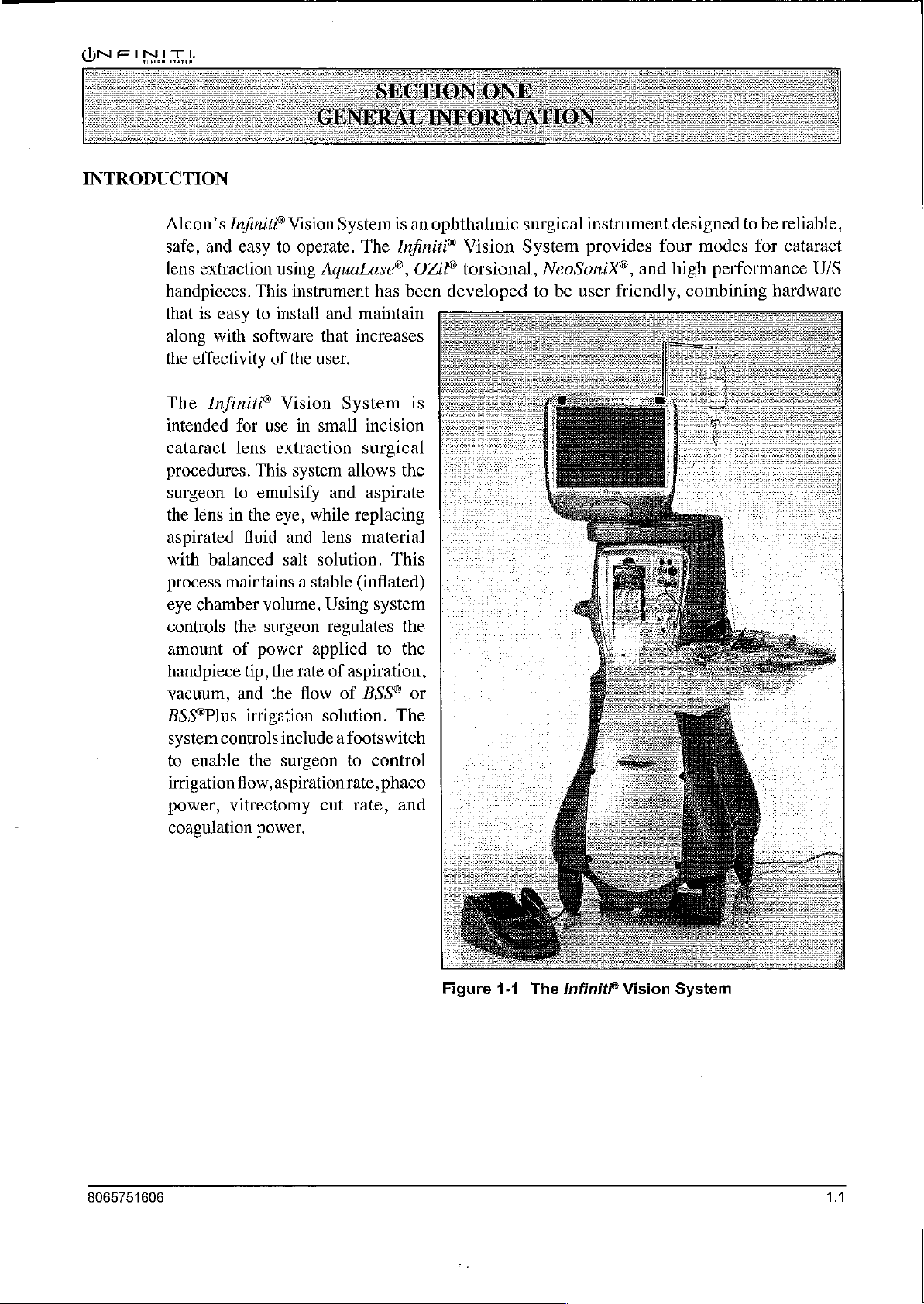
Alcon’s
safe,
lens
handpieces.
that
along
the
The
intended
cataract
procedures.
surgeon
the
aspirated
with
process
eye
controls
amount
handpiece
vacuum,
BSS®Plus
system
to
irrigation
power,
coagulation
Infiniti®
and
easy
to
extraction
is
easy
with
effectivity
Infiniti?
lens
in
balanced
maintains a stable
chamber
controls
enable
vitrectomy
using
This
to
install
software
of
Vision
for
use
lens
extraction
This
to
emulsify
the
eye,
fluid
salt
volume.
the
surgeon
of
power
tip,
the
and
the
irrigation
include a footswitch
the
surgeon
flow,
aspiration
power.
Vision
the
and
System
operate.
instrument
in
system
while
applied
rate
flow
The
AquaLase®,
and
maintain
that
increases
user.
System
small
surgical
allows
and
replacing
lens
material
solution.
(inflated)
Using
regulates
of
aspiration,
of
BSS®
solution.
to
rate,
cut
rate,
is
an
Infiniti?
OZil®
has
been
is
incision
the
aspirate
This
system
the
to
the
or
The
control
phaco
and
ophthalmic
Vision
torsional,
developed
surgical
System
to
instrument
provides
NeoSoniX®,
be
user
designed
four
and
high
friendly,
combining
to
be
reliable,
modes
for
performance
hardware
cataract
U/S
8065751606
Figure
1-1
The
Infiniti?
Vision
System
11
Page 10
GENERAL
INFORMATION
The
Infiniti?
require
simultaneous
associated
purpose:
and
every
to
control.
patient.
Following
*
Customized
-
OZil®
used
-
AquaLase®
-
Infiniti?
sonic
-
High
lightweight,
*
Advanced
*
Fully
*
Modularized
Management
*
Emulation
+
Ability
*
Bipolar
*
Several
pulsed,
management.
*
Automated
*
Linear
loop
offers
*
Linear
removal
*
Linear
*
On-demand
«
Programmable,
«
Ability
I/A,
and
*
Ability
+
Emission
*
Voice
«
Flat
screen,
rotatable.
«
High-tech
*
Multi-channel
Vision
System
cataract
procedures
make
The
are
key
such
it
simple
system
features
cataract
torsional
exclusively
handpiece
or
liquefaction
NeoSonix®
oscillations.
performance
autoclavable.
fluidics
with
programmable,
fluidic
System
of
venturi-like
to
drive a high
coagulation
traditional
and
“burst”
IV
footswitch
modalities
pole,
control
low-end
footswitch
control
modes.
footswitch
control
continuous
pressurized
to
set
vacuum
VIT
steps.
to
switch
of
between
variable
confirmation
active
matrix
graphical
wireless
is
designed
lens
as
vitrectomy
to
operate, and
is
designed
of
the
lens
removal
with
alternated
device
handpiece
Infiniti?
U/S
quick,
for
extraction,
and
to
to
allow
Infiniti?
Vision
options:
ultrasonic
with
traditional
handpiece,
combining
handpiece:
smooth
control
multi-microprocessor
connections
(FMS).
fluidic
performance
achieved
performance.
/nfiniti®
capability.
of
ultrasonic
application
controlled
of
via the
of
ultrasonic
ultrasonic
front
power
control).
of
aspiration
of
vacuum
flow
in
irrigation.
levels
tones
during
user
interface.
remote
reflux
surgical
for
surgical
color
via
the
and
aspiration
steps
confirmation
step
LCD
with
control.
use
in
anterior
irrigation,
coagulation.
allow
the
surgeon
the
surgeon
System:
torsional
phaco.
technology,
the
features
40
kHz,
of
peristaltic
control.
with
the
vitrectomy
power
I/A,
footswitch.
flow
using
or
mode
touch
power,
panel,
in
U/S
rate
(AFR)
VIT,
and
rates
touch
of
system
changes.
screen
control
segment
and
It
was
procedures
aspiration,
developed
tremendous
to
customize
oscillations
and
accessories.
of a phaco
piezoeléctric,
aspiration.
disposable
as
well
footswitch,
steps
lens
to
screen,
operational
display
Fluidic
guillotine
including
as
duty cycle
or
(sophisticated
in
I/A,
VIT,
removal
desired
remote,
that
as
well
with a dual
versatility
the
treatment
.
which
can
handpiece
,
slim,
cutter.
continuous,
remote
control.
control
and
lens
modes.
levels
in
phaco,
or
footpedal.
status.
is
tiltable
that
as
of
be
with
and
1.2
8065751606
Page 11
Abbreviation
Many
described
Accessory
Accessory
according
equipment,
shall
equipment
by
Alcon
Standard
your
Follow
recycling
User
Information — Environmental
Descriptions
of
the
in
Equipment
equipment
to
and
comply
or
is
responsible
TEC
local
Alcon
local
of
abbreviations
Table
1-5.
the
respective
IEC
with
System
otherwise
60601-1-1.
representative.
governing
device
used
in
this
Icons
are
identified
connected
60601-1
IEC
for
to
Standard
medical
Standard
causing a different
for
continued
If
in
doubt,
ordinances
components
and
Considerations
manual
in
or
used
with
(e.g.,
equipment).
IEC
60601-1-1.
system
compliance
consult
and
recycling
packaging.
and
on
the
Figure
this
IEC
950
1-2.
equipment
Furthermore,
Anyone
configuration
to
the
the
Technical
plans
Infiniti?
Vision
must
for
data
processing
connecting
than
requirements
Services
regarding
disposal
System
be
certified
all
configurations
additional
provided
of
System
department
or
or
are
Pb
The
equipment
production.
potential
In
order
mote
back
systems.
end-of-life
assistance
The
crossed-bin
tems,
and
not
cates
If
you need
you,
please
Alcon
Universal
that
This
effect
to
natural
on
avoid
resource
Such
eguipment
in
take-back
while
also
dispose
that
the
labeled
more
contact
office
for
Precautions
you
have
equipment
the
environment
the
entry
of
conservation,
take-back
in a beneficial
options
symbol
located
emphasizing
of
it
as
unsorted
device
information
your
local
more
information.
purchased
may
also
and
any
such
we
systems
through
on
this
the
requirement
municipal
contains
on
the
or
regional
requires
contain
human
substances
encourage
reuse
way.
Please
Alcon
eguipment
greater
the
hazardous
health
into
you
or
recycle
contact
or
other
reminds
to
collect
waste.
than
The
0.004%
use
collection, reuse
waste
administration,
of
natural
substances
if
disposed
our
environment
to
use
the
many
of
the
your
local
providers.
you
to
waste
equipment
Pb
notation,
lead.
or
recycle
or
resources
which
of
could
improperly.
and
to
appropriate
materials
Alcon
use
office
take-back
separately,
if
present,
systems
contact
available
your
for
its
have
pro-
take-
in
your
for
sys-
indi-
local
to
8065751606
Universal
precautions
instrument
and/or
status
other
of
blood
considered
national
guidelines.
shall
and/or
accessories
potentially
or
body
potentially
infectious
be
observed
to
help
infectious
fluids/tissues
and
by
prevent
materials.
encountered
handled
all
people
their
In
any
in
accordance
who
come
exposure
to
blood-borne
circumstance,
are
unknown,
with
in
contact
wherein
it
shall
OSHA
with
pathogens
the
exact
be
uniformly
or
your
the
own
13
Page 12
EMC
It
is
in
equipment
equipment
or
Statement
important
order
to
prevent
causes
off
more
of
the
to
install
and
harmful
harmful
and
on),
the
following
use
the
equipment
interference
interference
user
is
encouraged
measures:
with
to
other
in
accordance
other
devices
devices
to
try
to
with
in
the
(determined
correct
the
the
instructions
vicinity.
by
turning
If
this
interference
the
by
one
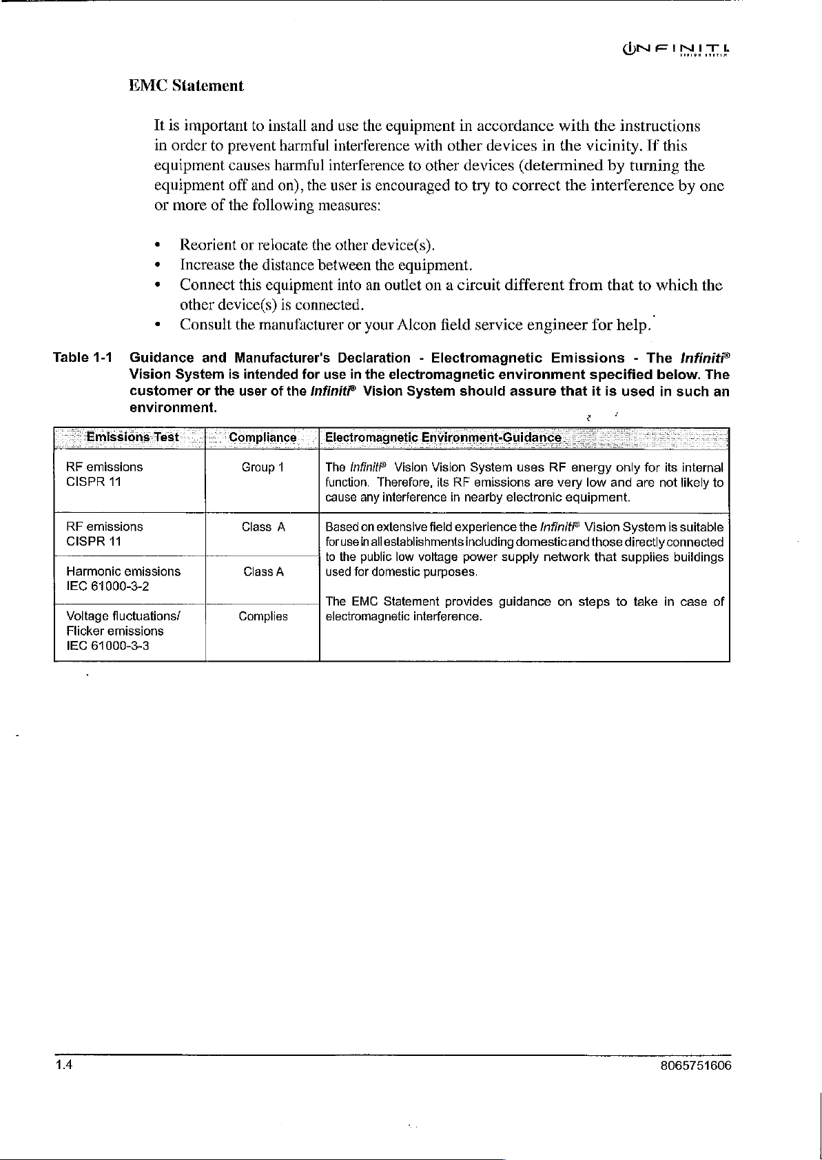
Table
1-1
Guidance
Vision
customer
environ
=
Emissions
RF
emissions
CISPR
RF
emissions
CISPR
Harmonic
IEC
61000-3-2
Voltage
Flicker
emissions
IEC
61000-3-3
Test
11
11
emissions
fluctuations/
Reorient
Increase
Connect
other
device(s)
Consult
and
System
ment.
or
is
the
Compliance : |
or
relocate
the
distance
this
equipment
the
manufacturer
Manufacturer's
intended
user
is
connected.
for
of
the
Infiniti?
the
between
use
Electromagnetic
Group
1
Class
A
Class
A
Complies
The
function.
cause
Based
forusein
to
used
The
electromagnetic
other
device(s).
the
equipment.
into
an
outlet
on a circuit
or
your
Alcon
Declaration - Electromagnetic
in
the
electromagnetic
Vision
field
System
should
different
service
environment
assure
Environment-Guidance
Infinit?
the
EMC
Vision
Vision
Therefore,
any
interference
on
extensive
allestablishments
public
for
domestic
Statement
field
low
voltage
purposes.
interference.
System
its
RF
emissions
in
nearby
experience
including
power
provides
uses
electronic
the
domestic
supply
guidance
from
that
engineer
RF
are
Infiniti?
network
for
Emissions - The
specified
that
it
is
로
energy
very
low
and
equipment.
Vision
and
those
that
on
steps
to
help.
used
only
for
are
System
directly
suppiies
to
take
which
Infinit
below.
in
such
its
internal
not
likely
is
suitable
connected
buildings
in
case
the
The
an
to
of
14
8065751606
Page 13
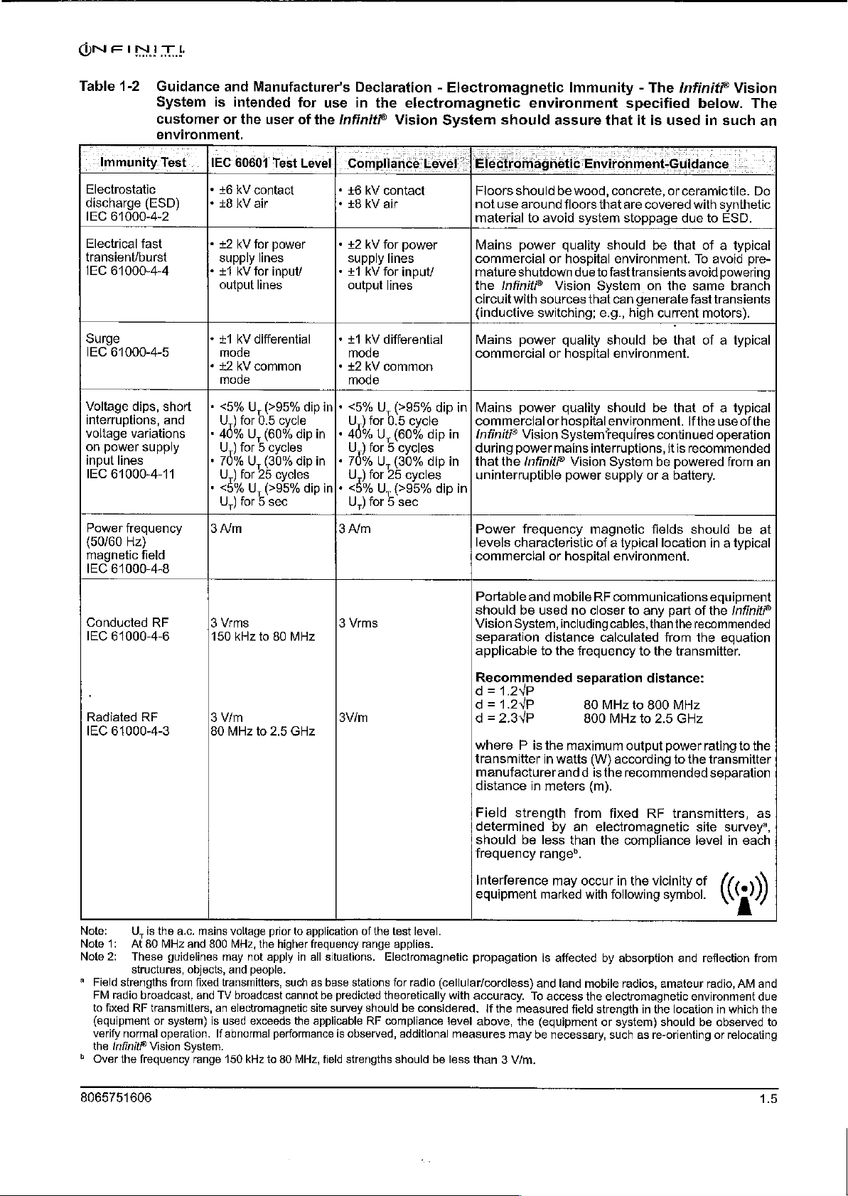
Table
1-2,
Guidance
System
customer
Immunity
Electrostatic
discharge
IEC
61000-4-2
Electrical
transient/burst
IEC
61000-4-4
Surge
IEC
61000-4-5
Voltage
interruptions,
voltage
on
power
input
IEC
61000-4-11
Power
(50/60
magnetic
IEC
61000-4-8
Conducted
IEC
61000-4-6
environment.
Test...
(ESD)
fast
dips,
variations . ον
supply
lines
frequency
Hz)
field
RF
short
and
and
Manufacturer's
is
intended
or
the
[IEC
60601
*
+6
kV
+
*
*
+
* 2 kV
|"
.
70% U U,
.
3
3
150
contact
28
kV
air
+2
kV
for
supply
+1
kV
for
output
+1
kV
differential * +1
mode
common
mode
Oye
U,
)
for
U.)
for A cycles
)
for
3%U
U,)
for E sec
Alm
Vrms
kHz
user
Test
power
lines
input/
lines
(295%
05
cycle
(60%
(30%
25
cycles
(295%
to
80
MHz
for
of
the
Lével
dip
{πι
dipin
dip
in
dip
Declaration - Electromagnetic
use
in
the
electromagnetic
Infiniti?
|:
Compliance
*
+6
»
£8
*
#2
supply
*
+1
output
mode
*
+2
mode
Seu , (>95%
U)
|-
40%
|"
76%
in|«
Be
U,)
3
Alm
3
Vrms
Vision
kV
contact
KV
air
kV
for
power
lines
KV
for
input/
lines
kV
differential
kV
common
for
05
cycle
U,
(60%
)
for 5 cycles
U,
(80%
)
for
25
cycles
U,
(9596
for 5 sec
System
Level: | Electromagnetic
not
material
commercial
mature
the
circuit
{inductive
commercial
dip
in]
dip
dip
commercial
in | Infiniti"
during
in | that
dip
in
commercial
should
Vision
separation
applicable
environment
should
Floors
use
Mains
Infinite
Mains
Mains
the
uninterruptible
Power
levels
Portable
assure
should
be
around
power
shutdown
with
power
power
power
characteristic
be
System,
floors
to
avoid
guality
or
hospital
Vision
sources
switching;
quality
or
hospital
quality
or
hospital
Vision
SystemY
mains
Infinit
power
frequency
or
hospital
and
mobile
used
including
distance
to
the
Immunity - The
specified
that
it
is
used
Environment-Guidance
wood,
concrete,
that
system
due
Vision
no
frequency
are
stoppage
should
environment.
to
fasttransients
System
that
can
e.g.,
should
environment.
should
environment.
requires
interruptions,
System
supply
magnetic
of a typical
environment.
RF
communications
closer
cables,
calculated
or
covered
be
that
on
the
generate
high
current
be
that
be
that
continued
itis
be
powered
or a battery.
fields
location
to
any
part
than
the
from
to
the
transmitter.
Infinit®
ceramic
due
avoid
fast
Ifthe
recommended
should
Vision
below.
in
such
tile.
with
synthetic
to
ESD.
of a typical
To
avoid
powering
same
branch
transients
motors).
of a typical
of a typical
use
operation
from
in a typical
equipment
of
the
Infiniti?
recommended
the
equation
of
be
The
an
Do
pre-
|
the
an
at
Radiated
IEC
Note:
Note
Note
*
Field
FM
to
(equipment
verify
the
©
Over
8065751606
RF
61000-4-3
U,
is
1:
At
80
2:
These
structures,
strengths
radio
broadcast,
fixed
RF
transmitters,
normal
Infinite
Vision
the
frequency
the
a.c.
mains
MHz
and
guidelines
objects,
from
fixed
and
or
system)
operation.
System.
range
3
Vim
80
MHz
to
voltage
800
MHz,
may
not
and people.
transmitters,
TV
broadcast
an
electromagnetic
is
used
exceeds
If
abnormal
150
kHz
2.5
GHz
prior
to
the
higher
apply
in
such
cannot
the
performance
to
80
MHz,
3Vim
application
frequency
all
as
site
applicable
of
range
situations.
base
stations
be
predicted
survey
should
RF
is
observed,
field
strengths
the
test
level.
applies.
Electromagnetic
for
radio
theoretically
compliance
should
(cellular/cordless)
be
considered.
additional
be
with
ievel
measures
less
Recommended
d=
1.2VP
d=1.2VP
d=2.3YP
where P is
transmitter
manufacturer
distance
Field
determined
should
frequency
Interference
equipment
in
strength
be
separation
the
maximum
in
watts
and d is
meters
from
by an
less
than
range”.
may
marked
distance:
80
MHz
to
800
(W)
the
(m).
electromagnetic
the
occur
with
800
MHz
to
output
according
recommended
fixed
RF
compliance
in
the
vicinity
following
propagation
accuracy.
If
the
above,
than 3 V/m.
and
To
measured
the
(equipment
may
be
is
affected
land
mobile
access
field
necessary,
by
absorption
radios,
the
electromagnetic
strength
or
system)
such
in
as
re-orienting
MHz
2.5
GHz
power
rating
to
the
transmitter
separation
transmitters,
site
level
of
symbol.
and
reflection
amateur
the
should
radio,
environment
location
be
or
to
the
as
survey’,
in
each
(0)
from
AM
in
which
observed
relocating
and
due
the
to
15
Page 14

Table
1-3
Rated
power
For
transmitters
be
estimated
transmitter
Note
1-
Note
At
2-
These
structures,
Recommended
Equipment
electromagnetic
or
the
maintaining a minimum
(transmitters)
output
maximum
of
transmitter:
AM
0.01
0.1
1
10
100
rates
using
the
in
watts
(W)
80
MHz
and
guidelines
objects,
and
user
of
and
power
china
outpui
at a maximum
equation
according
800
may
applicable
MHz,
not
and
the
of
to
people.
Separation
the
Infiniti?
environmentin
Infiniti?
distance
the
Infinit?
the
communications
0.12
0.38
output
power
to
the
the
apply
the
transmitter
separation
in
all
situations.
Distances
Vision
which
Vision
between
Vision
1.2
3.8
12 12
not
listed
frequency
manufacturer.
distance
Electromagnetic
Between
System - The
radiated
System
System
can
portable
as
equipment.
above,
the
of
for
the
the
recommended
transmitter,
higher
Portable
Infiniti?
RF
disturbances
help
prevent
and
recommended
according
A)
80-MHz
frequency
to
dep:
0.12
0.38
1.2
38
where P is
propagation
and
Mobile
Vision
mobile
800-MHZ
System
are
electromagnetic
RF
communications
below,
to:frequency-of.transmitter
di
RF
is
intended
controlled.
according
800
|
separation
range
is
the
maximum
applies.
affected
distance
output
by
absorption
d in
meters
power
NE
Communications
to
MHZ
ミ
d
and
INTL
for
use
in
The
customer
interference
eguipment
the
maximum
to
2.5
2.3YP
GHz
0.23
0.73"
23-
73
23
(m)
can
rating
of
the
reflection
from
an
by
1.6
8065751606
Page 15
ON
FINE
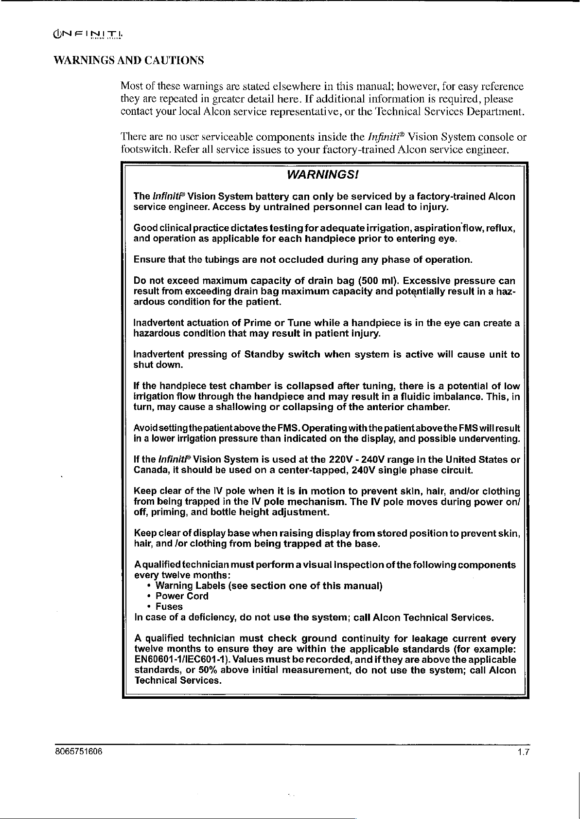
WARNINGS
AND
CAUTIONS
Most
of
these
they
are
repeated
contact
There
footswitch.
your
are
no
The
Infinit?
service
Good
and
Ensure
Do
result
ardous
Inadvertent
hazardous
engineer.
clinical
operation
that
not
exceed
from
condition
warnings
in
local
Alcon
user
serviceable
Refer
all
Vision
practice
as
the
tubings
maximum
exceeding
actuation
condition
are
stated
greater
service
System
Access
applicable
for
detail
service
by
dictates
are
capacity
drain
the
patient.
of
Prime
that
may
elsewhere
here.
If
representative,
components
issues
battery
untrained
testing
for
each
not
occluded
bag
maximum
or
result
to
your
WARNINGS!
can
only
for
handpiece
of
drain
Tune
in
in
this
manual;
additional
inside
factory-trained
be
personnel
adequate
during
bag
capacity
while a handpiece
patient
information
or
the
Technical
the
/nfiniti®
serviced
can
irrigation,
prior
any
(500
and
injury.
lead
to
phase
ml).
however,
Vision
Alcon
by a factory-trained
to
entering
Excessive
potentially
is in
for
is
required,
Services
System
service
injury.
aspiration
eye.
of
operation.
result
the
eye
easy
Department.
console
engineer.
flow,
pressure
in a haz-
can
reference
please
or
Alcon
reflux,
can
create
a
Inadvertent
shut
down.
If
the
handpiece
irrigation
turn,
Avoid
in a lower
If
the
Canada,
Keep
from
off,
Keep
hair,
Aqualified
every
*
*
*
In
case
flow
may
cause a shallowing
setting
irrigation
Infiniti?
it
should
clear
being
priming,
clear
of
and
/or
technician
twelve
Warning
Power
Fuses
of a deficiency,
pressing
test
through
the
patientabove
Vision
be
of
the
IV
trapped
and
bottle
display
clothing
months:
Labels
Cord
of
Standby
chamber
the
handpiece
pressure
System
used
on a center-tapped,
pole
when
in
the
IV
height
base
when
from
being
must
(see
section
do
not
switch
is
collapsed
or
collapsing
the
FMS.
than
indicated
is
used
it
is
pole
mechanism.
adjustment.
raising
trapped
perform a visual
one
use
the
when
and
Operating
at
the
in
motion
display
at
of
this
system;
system
after
tuning,
may
result
of
the
anterior
with
the
on
the
display,
220V - 240V
240V
to
prevent
The
IV
from
the
base.
inspection
manual)
call
Alcon
is
active
there
in a fluidic
chamber.
patient
single
pole
stored
of
and
range
skin,
moves
the
Technical
above
in
phase
position
following
will
is a
potential
imbalance.
the
possible
the
United
circuit.
hair,
and/or
during
to
Services.
cause
FMS
underventing.
components
This,
will
States
clothing
power
prevent
unit
of
low
result
on/
skin,
to
in
or
8065751606
A
qualified
twelve
EN60601-1/IEC601-1).
standards,
Technicai
technician
months
or
Services.
to
50%
must
ensure
Values
above
check
they
are
must
initial
ground
within
be
measurement,
the
recorded,
continuity
applicable
and
if
they
do
not
for
leakage
standards
are
use
the
above
system;
current
(for
example:
the
applicable
call
every
Alcon
17
Page 16
WARNINGS!
Use
of
accessories
emissions
communications
or
and
decreased
equipment
cables
immunity
can
other
affect
than
of
this
those
the
medical
provided
system.
electrical
may
result
Portable
equipment.
and
in
increased
mobile
RF
Handpiece
The
Infiniti?
handpieces
should
the
handpiece
dry
before
Directions
If
in
undergoes
processed
The
Infiniti?
temperature
after
autoclaving;
Never
U/S
handpieces;
Care
AquaLase®,
are
surgical
not
touch
connecting
for
the
ultrasonically
any
solid
must
be
thoroughly
it
Use
(DFU)
medical
according
NeoSonix® , OZil®
just
a
high
before
never
opinion
risk
clean
irreparable
OZil®
instruments
to
to
use.
immerse
torsional,
object
console.
supplied
procedure,
local
while
cleaned. Be
of
the
requirements.
torsional,
Allow
the
and
For
with
physician a patient
the
CAUTIONS
the
Infiniti®
damage
NeoSoniX®,
must
be
in
operation.
cleaning
the
handpiece.
WARNING!
the
instrument
and
U/S
handpiece
handpiece
AquaLase®,
may
result.
handled
Immediately
sure
handpiece
and
sterilization
handpieces
to
air
in
liquid
and
high
with
care.
connector
with a prion
should
must
cool
for
when
OZiP
torsional,
performance
The
following
procedures,
related
bé
destroyed
be
at
least
hot.
U/S
handpiece
surgery
is
completely
disease
at
room
15
minutes
NeoSoniX®,
tip
see the
or
be
or
Prior
U/S
the
during
Do
immersed
use.
Ensure
tuning
may
Quenching a hot
Be
handpiece
to
sterilization,
handpieces
sterilization
handling,
not
operate
in
BSS®
Irreparable
that
test
OZil®
result
sure
torsional,
in
premature
handpiece
and
console
the
should
tray.
This
and
especially
OZil®
torsional,
sterile
damage
chamber
handpiece
is
completely
Infiniti?
always
will
AguaLase?,
have
prevent
during
NeoSoniX®,
irrigating
to
the
handpiece
is
filled
with
NeoSoniX®,
tip
failure
in
water
dry
may
result
the
connector
damage
autoclaving.
solution
and
BSS®
or
U/S
handpieces.
and
breakage.
can
cause
before
if
plugged
OZiF
torsional,
end
to
the
connectors
or
0/5
handpieces
or
distilled
tip
can
sterile
connecting
in
irrigating
damage
when
wet.
NeoSoniXº,
cap
secured
water
result
if
and
and
handpieces
unless
or
run
solution
is
in
dry.
the
surgical
before
placed
tip
Tuning a handpiece
and
will
void
warranty.
it
to
console.
Damage
and
in
is
dry
to
18
8065751606
Page 17
DN
FINIT
L
Use
absence
can
of
the
cause
OZIiF
of
irrigation
excessive
torsional,
flow
heating
Infiniti?
and/or
in
and
WARNINGS!
NeoSoniX®,
the
presence
potential
thermal
U/S,
of
or
AquaLase®
reduced
injury
or
to
adjacent
handpiece
lost
aspiration
eye
in
the
flow
tissues.
Appropriate
for
successful
heights,
conditions
power,
result
lead
to
Use
of
or
U/S
not
permitted,
patient
The
U/S
ОР
torsional,
be
used
ordinances.
Use
0.9
1.1
mm
tips
and
Directing
use
high
power
(beeping
excessively
in
significant
severe
an
ultrasonic
handpiece,
and/or
tips
supplied
only
once
mm
U/S
liquefaction
infusion
energy
of
Infiniti?
procedures.
settings,
tones),
tight
temperature
thermal
and
operator.
Infinit®
tips
eye
handpiece
or
use
may
result
in
the
NeoSonixX®,
per
case,
exclusively
tips
exclusively
sleeves
toward
Vision
incisions,
of a handpiece
may
non-lens
Use
of
extended
failure
increases
tissue
other
in
patient
/nfinitP”
and
with
create
System
low
to
sufficiently
and
damage.
Vision
or
then
with
material
parameters
vacuum
power
usage,
combinations
at
incision
than
the
OZiF
repaired
injury,
U/S
disposed
0.9
potentially
including
System
handpieces.
mm
infusion
1.1
mm
may
and
limits,
power
aspirate
site
torsional,
without
pak
of
according
sleeves.
infusion
hazardous
cause
tissue
accessories
low
flow
rates,
usage
during
viscoelastic
of
the
above
and
inside
Infinit®
Alcon
potential
are
Each
sleeves.
authorization,
only
to
U/S
tip
to
Use
Mismatching
fluidic
damage.
is
important
low
occlusion
prior
to
actions
the
eye,
NeoSonix®,
shock
hazard
be
used
is
intended
local
governing
1.1
mm
U/S
imbalances.
bottle
using
may
and
is
to
on
the
to
and
U/S
IV
Pole
Once
bottle
IV
negatively
causing
Empirical
technique.
and
Extender
the
height
bottle
IV
pole
tothe
impact
false
numbers
The
extender
by
manually
lower
hook
the
indications
for
surgeon
is
installed,
hanging
will
introduce
performance
at
low
bottle
should
heights
visually
WARNINGS!
the
upper
the bottle on
an
error
of
the
Infusion
bottle
levels.
are not a replacement
and
physically
hook
the
in
lower
the
displayed
Pressure
monitor
is
to
hook.
be
used.
Manually
height
Drop
detection
for
competent
intraocular
Do
not
change
lowering
indication
feature,
surgical
pressure.
the
and
8065751606
1.9
Page 18
Феи
Ultraflow™*
Prior
Ultraflow™ * handpiece.
contact Alcon's
Use
Alcon
with
cause a shallowing
Exceeding
cause
capsule.
VA
Recommended
to
each
of
surgical
the
anterior
tips
(I/A)
Handpiece
procedure
Technical
non-Alcon
Infinit®
the
are
not
Vacuum
inspect
If
damaged
Services
surgical
specifications,
Vision
or
recommended
chamber
to
be
Range
reusable
System,
collapsing
shallowing
used
with
for
the
two
O-rings
or
missing,
Department.
WARNINGS!
or
or
use
of
may
result
of
the
level
of
100
and/or
NeoSoniX®,
I/A
Tips
where
replace
disposable
an
Alcon
in a fluidic
anterior
mmHg
incarceration
OZiP
the
tip
the
I/A
handpieces
handpiece
imbalance.
chamber.
with a 0.5
or
torsional,
screws
o-rings.
that
not
specified
This,
mm
or
larger
tearing
or
of
U/S
handpieces.
onto
If
in
do
in
the
the
doubt,
not
meet
for
turn,
I/A
tip
posterior
use
may
may
It
is
important
vacuum.
100
mmHg.
TA
adjustable
Handpiece
Ensure
an
error
not
too
Use
of a tool
and/or
Poor
During
touching
of
metal
ultrasonic
that
Only
0.2
vacuum
Tips
that
handpiece
may
be
generated
tight
so
that
other
handpiece.
clinical
performance
any
ultrasonic
of
the
particles
energy
only
the
mm
or
0.3
range
tip
is
and/or
it
can
be
than
tip
procedure,
ultrasonic
resulting
causing
proper
fully
wrenches
size
mm
I/A
is
0-650+.
tightened
inadequate
removed
will
result
tip
with a second
from
micro
abrasion
I/A
tip
tips
should
to
the
tuning
after
use.
supplied
WARNING!
if
tip
is
metal
any
particles
ultrasonic
of
be
used
when
be
used with
handpiece.
will
by
Alcon
not
secured
may
instrument.
handpiece
the
ultrasonic
operating
If
occur.
may
cause
tightly
result
Another
vacuum
not
securely
Ensure
damage
to
the
from
potential
may
be
tip.
with
maximum
limits
that
above
attached,
the
tip
to
the
handpiece.
inadvertent
source
the
result
is
tip
of
1.10
Check
tips.
tubing
for
Never
may
the
presence
attempt
result
and
correct
to
remove
in a hazardous
the
position
tubing.
condition
Use
of
of
for
the
the
the
polymer
Mackoo/"
patient.
tubing
tips
on
the
without
Mackoof*
polymer
8065751606
Page 19
ONFINITÙÀ
Infiniti®
Aspiration/Vacuum
Vitrectomy
The
Infiniti?
Do
not
test
BSS®
sterile
damage
After
erly
good
position
Prior
the
is
the
actuated,
*
If
»
If
priming,
+ H a
procedure,
to
filling
actuating
visualization.
1.
to
entry
surgeon
cutting;
cutter
cutting
air
bubbles
reduction
vitrectomy
or
irrigating
the
and
If
cutting
alternatively,
is
replace
port
replace
Probe
probe, a guillotine
operate
solution
handpiece
testing,
and
aspirating.
The
port
into
the
should
observed
stop
step
the
probe.
is
partially
are
observed
the
of
cutting
immediately
Adjustments
vitrectomy
and
tip
and
before
port
should
is
partially
eye,
and
on
the
press
the
to
not
fully
closed
in
probe.
capability
WARNINGS!
probes
or
distilled
can
surgical
This
always
closed
with
footpedal
Test
close,
while
the
aspiration
or
and
replace
vitreous
unless
water
result
may
tip
button
require
remain
while
of
probe
for
or
idle,
vacuum
the
if
use,
does
cutter,
tip
oris
run
dry.
verify
lowering
in
in
position
in
visual
on
the
not
replace
line
or
is
observed
probe.
is
intended
of
probe
in
surgical
that
the
cut
open
position
1,
replace
sterile
verification
Vitrectomy
the
exiting
move
irrigating
when
probe.
the
during
for
single
is
immersed
use.
İrreparable
probe
rate
in
that the
Setup
the
probe
the
use
is
prop-
to
achieve
footpedal
the
probe.
solution,
probe
Screen:
probe
tip
during
surgical
only.
in
if
is
Adjusting
aspiration
Dynamic
Care
must
Adjusting
the
IV
which
Presurgical
Presurgical
section.
the
If
Troubleshooting
When
fluidics
adequate
aspiration
levels
Rise
pole
may
Check-out
an
filling
(volumes)
values
be
taken
aspiration
below
result
check-out
error
message
handpiece
response
irrigation
rates
or
of
1,2,3,
not
to
engage
rates
the
preset
in
patient
Tests
tests
must
or
section
will
of
test
be
jeopardized.
and
aspiration
vacuum
exceeding
or 4 will
non-lens
WARNING!
or
vacuum
values,
injury.
be
performed
advisory
this
manual.
WARNINGS!
chamber,
flow
limits
above
irrigation
achieve
material.
limits
may
message
Good
If
the
if
stream
prior
above
cause
as
clinical
the
preset
inflow.
vacuum
the
chamber
outlined
is
displayed
problem
of
fluid
practice
to
entering
values
in
shorter
preset
in
persists,
values,
shallowing
the
Operating
on
the
DO
is
weak
dictates
the
eye.
may
periods
front
NOT
or
absent,
the
result
or
or
panel,
in
of
time.
lowering
collapse
Instructions
refer
PROCEED.
good
testing
for
to
8065751606
Ensure
that
tubings
are
not
occluded
or
pinched
during
any
phase
of
operation.
1.11
Page 20
Footswitch
ONE
INET
|
Never
footswitch
If
required,
germicidal
Do
not
compatible
Damage
High
Altitudes
Vitrectomy
Service
Occlusion
Two
different
that
the
stopped
when
or
AquaLase®
single
intermittent
ultrasonic
pick
up
or
can
cause
the
footswitch
solution
clean
may
the
with
result.
cutting
for
additional
Tones
occlusion
vacuum
to
avoid
occlusion
system
beep.
The
double
power
move
the
irreparable
that
is
footswitch
plastic
parts
performance
information.
tones
is
near
or
exceeding
occurs
during
magnitude),
second
or
type
beep,
AquaLase®
footswitch
damage.
may
be
wiped
compatible
using
solvents,
made
may
(intermittent
at
its
preset
the
limit.
aspiration
The
of
occlusion
and
sounds
system
by
the
cable.
with
with
the
CAUTION
abrasives,
of
GE
Cycoloy
vary
at
high
beeping
limit,
and
The
first
only
I/A
occlusion
tone,
when
occlusion
magnitude.
Dropping
alcohol,
plastic
parts.
CU
altitudes.
tones
aspiration
type,
the
(in
the
absence
tone
the
phaco
occurs
or
mild
soap
or
any
6800
Consult
during
flow
I/A
occlusion
of
is a lower,
occlusion
during
kicking
and water,
cleaner
and
the
that
LEXAN
Alcon
로
occlusion)
is
reduced
tone,
ultrasonic
intermittent
tone,
is a higher,
application
or
any
is
not
920A.
Technical
indicate
or
sounds
power
of
The
I/A
occlusion
maximum
phaco
The
and/or
Use
of
excessive
Vacuum
A
vacuum
high
in
volume,
allowed
occlusion
phaco
prolonged
of
the
irrigation
Tone
tone
vacuum
but
and
preset
tone
occlusion
use
NeoSoniX®,
flow
and/or
heating
can
not
and
is
provided.
indicate
turned
phaco
value.
cannot
bell
may
OZiF
in
potential
that
off.
occlusion
The
be
turned
WARNINGS!
indicates
lead
to
torsional,
the
presence
thermal
The
pitch
little
to
tones
I/A
occlusion
off.
no
thermal
U/S,
of
will
no
flow
indicate
aspiration
injury.
or
AquaLase®
reduced
injury
vary
to
relative
is
occuring.
that
tone
can
flow.
or
lost
adjacent
to
the
vacuum
be
turned
Use
of
high
handpiece
aspiration
eye
tissues.
the
amount
This
tone
has
off,
U/S
in
the
flow
of
can
reached
while
the
settings
absence
can
cause
vacuum.
be
reduced
8065751606
its
A
Page 21
WARNINGS!
A
moderate
the
NeoSonix®,
irrigation
excessive
Do
not
result
hazardous
Coagulation
to
flow
heating
exceed
from
exceeding
condition
Function
high
OZiF
and/or
and
maximum
vacuum
torsional,
in
the
potential
capacity
drain
for
the
tone
may
U/S,
presence
thermal
bag
maximum
patient.
indicate
or
of
of
drain
little
AquaLase®
reduced
injury
to
bag
capacity
to
handpiece
or
lost
adjacent
(500
mi).
no
flow
aspiration
eye
Excessive
and
potentially
is
occuring.
in
the
absence
flow
tissues.
pressure
Use
can
cause
result
of
of
can
in
a
8065751606
Listed
+
below
To
ensure
and
accessories
performance
endorsed
*
To
reduce
operating
¢
Interference
adversely
«
Accessories
checked
+
Operation
*
The
lowest
intended
*
Skin-to-skin
should
«
When
equipment
should
electrodes
+
In
devices
«
The
contact
*
Temporarily
from
*
The
and
the
*
Non-flammable
¢
Flammable
should
materials,
be
*
Accessories
coagulation
be
HF
be
all
cases,
cables
with
the
use
oxygen
thorax
be
ignited
are
general
safe
operation
can
precautions
must
be
guaranteed
components.
the
risk
of
accidental
high-frequency
produced
influence
should
for
possible
of
the
power
purpose.
contact
avoided,
(high
are
placed
are
monitoring
are
recommended.
to
the
the
unused
patient.
of
flammable
should
or
the
agents
allowed
for
by
sparks
should
output
the
be
damage
coagulation
level
(for
for
frequency)
used
simultaneously
as
far
not
recommended.
surgical
patient
active
be
head,
agents
used
to
example
produced
have a rated
voltage.
to
of
the
coagulation
be
used
(See
only
burns,
surgical
by
the
operation
operation
checked
in
example
example
as
systems
or
anaesthetics
avoided
unless
should
for
evaporate
cotton,
regularly;
to
the
step
coagulation
by
surgical
possible
incorporating
electrodes
other
leads
electrodes
if a
these
be
used
cleaning
before
wool
in
normal
voltage
be
followed
function,
your
Alcon
when
using
caution
equipment.
of
high-frequency
of
other
electronic
electrode
insulation.
is
limited
step
should
between
the
insertion
equipment
on
the
same
from
the
should
is
avoided.
should
or
oxidizing
surgical
agents
for
or
and
procedure
are
cleaning
disinfecting,
the
application
gauze,
use
equal
when
using
the
only
approved
representative).
Alcon
components
г
should
to
extraocular
arms
of
dry
surgical
high
be
positioned
be
sucked
of
to
always
surgical
equipment.
cables
uses
always
and
be
body
gauze.
and
physiological
patient,
stored
gases
and
when
the
or
any
electrodes.
frequency
in
so
that
such
is
carried
away.
disinfection
or
as
solvents
of
HF
saturated
HF
surgical
greater
should
as
Coagulation
Coagulation
be
taken
equipment
particularly
only.
selected
of
the
monitoring
monitoring
Needle
current-limiting
such a way
they
are
nitrous
out
wherever
of
surgery.
with
equipment.
than
the
function:
cables
or
Alcon-
when
for
the
patient)
electrodes
monitoring
that
isolated
oxide
in
the
region
possible.
adhesives,
Some
oxygen
maximum
may
be
(N,O)
of
may
1.13
Page 22
Coagulation
Do
not
defibrillatory
pacemakers
irreparable
may
occur
or
defibrillatory
Failure
unintended
The
Infiniti?
discharge.
Cautery,
The
Diathermy,
Diathermy,
Infiniti®
Function
use
the
devices.
or
damage
and
of
the
HF
increase
Vision
Vision
based
(from
coagulation
defibrillatory
lead
device
Coagulation
System
on
prior
If
electrosurgery
to
the
to
ventricular
manufacturers
surgical
of
output power.
System
the
is
uses
following
pacemaker
equipment
page)
WARNINGS!
function
devices
on
fibrillation.
CAUTION
not
protected
Definition
the
word
definition:
patients
is
used
or
pacemaker
or
defibrillatory
for
their
(coagulation
against
“Coagulation”
with
on
patients
Please
recommendations.
the
pacemakers
with
electrodes,
device
check
circuitry)
effects
in
place
or
implanted
be
and
its
with
the
pacemaker
could
of
of
result
defibrillator
Cautery
implanted
cardiac
aware
that
function
in
or
an
Coagulation - Isolated,
forceps).
“Coag”
Infiniti?
Do
Refer
Do
*
Do
*
Use
to
Current
in
some
VideOverlay
not
remove
servicing
not
simultaneously
not
use
multiple
only
the
Alcon-supplied
the
IVO.
bipolar,
passes
of
between
the
text
System
VideOverlay
to
gualified
portable
of
this
(IVO)
touch
high
frequency
these
electrodes,
operator’s
WARNINGSI
cover;
service
serial
there
the
VideOverlay
CAUTIONS
socket
cable
personnel.
current
manual.)
are
outlets
to
connect
supplied
halting
no
user-serviceable
enclosure
with
this
the
to
conductors
bleeding.
and
system.
Infiniti®
(Abbreviated
the
Vision
parts
patient.
inside.
System
(e.g.
8065751606
Page 23

Consumable
Consumable
to
be
used
All
Infiniti®
stand
the
NOTE:
manual
accessory,
Mismatch
a
particular
Do
Sterile
been
Paks
once
paks
DFU’s
If
an
and
follow
of
not
use
disposable
designed
items
used
with
and
then
discarded,
contain
prior
inconsistency
the
Directions
the
consumable
combination
paks
for
to
DFU
that
have
medical
one
use.
Directions
time
the
Infiniti?
unless
exists
For
between
Use
‘WARNINGS!
components
of
consumable
exceeded
devices
use
only;
for
Use
(DFU)
and use
the
should
do not
Vision
labeled
(DFU).
the
supplied
of
components
expiration
not
be
reuse.
System
instructions
during
otherwise.
It
is
important
with a consumable
settings
reused!
may
date.
not
create a patient
These
surgery
to
in
the
specially
components
are
designed
read
and
under-
operator’s
pak
adjusted
hazard.
have
or
for
The
equipment
plete
surgical
system
contributed
voidance
In
all
cases,
thoroughly
Read
Miscellaneous
all
Do
not
Avoid
handpiece
Do
at
should
Do
The
for
spilling
not
the
rear
be
not
USB
use
Tray
used
in
conjunction
system.
performance
to
the
of
the
the
understood
package
use
the
/nfiniti®
BSS®
connectors.
push
or
pull
and
sides
pulled
place
more
connector ( *&* ) and
by
Alcon
support
Use
and
malfunction
contract
instrument
prior
label
material
Vision
solution,
the
unit
of
the
and
not
pushed,
than a 20
trained
must
personnel
be
create
and/or
of
disposables
potential
of
the
invoicing
setup
instructions
to
using
printed
CAUTIONS
System
or
moisture
by
the
unit
are
provided
especially
lb.
load
Infiniti?
set
in
its
with
the
Alcon
other than
hazards,
equipment
at
any
of
on
the
near
flammable
of
display,
on
only.
the
for
over
tray
port
Failure
WARNING!
stored
position
disposables
Alcon
and
under
prevailing
contained
the
pak
configurations.
consumable
any kind,
tray,
or
moving
elevator
support.
(d+)
to
comply
when
constitutes a com-
disposables
if
it
is
determined
contract,
hourly
in
anesthetics.
around
the
the
and
located
moving
could
rates.
the
manual
paks
prior
the
electrical
IV
pole.
instrument.
door
thresholds.
on
the
will
void
instrument.
may
to
result
should
to
their
Handles
The
unit
rear
panel
warranty.
affect
have
in
the
be
use.
located
are
8065751606
Page 24

PRODUCT
SERVICE
For
product
number
service,
provided
please
below.
contact
Alcon’s
Technical
Services
Department
at
the
Operators
Instructions
should
authorized
For
optimum
maintenance
year.
Alcon’s
quality
Safety
least
must
To
avoid
Department
deemed
shipping
experiencing
and
be
referred
service
Additional
Field
of
workmanship.
performance
twice a year.
be
checked
unnecessary
prior
necessary, a Return
instructions.
problems
Troubleshooting
to
the
Alcon
representative.
performance,
service
Service
on
the
preventive
Engineers
should
Ground
to
appropriate
shipping,
to
return
Alcon
Irvine,
(800)
Technical
15800
832-7827,
with
sections
Technical
it
is
the
user’s
system
maintenance
be
resistance,
of
Material
California
and
are
trained
verified
national
please
any
system
Authorization
Services
Alton
or
leakage
Parkway
(949)
the
system
of
Services
responsibility
its
accessories a minimum
may
and
by
the
standard.
contact
or
should
this
manual. A problem
Department
be
required
equipped
user
(e.g.,
current,
your
and
Alcon
accessories.
will
Department
92618-3818
753-1393
refer
to
the
or
to
schedule
based
qualified
If
be
upon
to
provide
service
dielectric
Technical
return
of
issued
Operating
which
your
local
preventive
of
one
time
system
the
highest
personnel)
withstand
Services
the
equipment
with
appropriate
persists
per
use.
at
voltage
is
1.16
8065751606
Page 25
LIMITED
WARRANTY
Alcon
found
from
of
the
accordance
Alcon
or
destruction
or
caused
any
Act
earthquake.
This
warranty
by
any
provided
force
service
credit
service
will
repair
to
be
defective
the
date
of
system,
shall
of
person
and
personnel.
customer’s
or
when
with
not
of
by
fire
God
does
other
by
Alcon
effect
other
or
replace
in
material
initial
published
be
including,
if
alteration
installation.
said
obligated
systems
or
explosion
not
cover
than
with
respect
this
equipment
In
particular,
account
system
covered
an
at
its
option,
and/or
is
properly
instructions.
to
provide
where
of
any
but
not
limited
damage
Alcon-authorized
to
this
is
Alcon
for
the
cost
by
persons
any
workmanship
This
warranty
services
such
origin,
resulting
equipment
serviced
shall
of
the
other
system
installed,
damage
riot,
to
lightning,
service person,
by
have
equipment,
than
or
applies
under
civil
from
service
shall
anyone
no
obligation
Alcon-authorized
accompanying
for a period
to
the
original
maintained,
this
warranty
or
destruction
commotion,
windstorm,
become
other
which
and
repair
and
any
void
than
Alcon-authorized
to
has
service
accessories
of
one
(1)
year
purchaser
operated
for
damage
is a result
aircraft,
hail,
flood
|
or
other alteration
warranties
and
of
replace,
been
subject
in
to
of
war,
or
or
an
no
further
repair
to
personnel.
or
The
express
remedy
agreements,
including , without
purpose.
damages
The
constitute a complete
handpieces
performance
products
malfunction
at
prevailing
warranty above
provided
guarantees,
Alcon
arising
consumable
shall
other
or
handpieces
of
above
out
and
hourly
is
is
in
or
watranties — oral
limitation,
have
no
of
any
defect,
products
surgical
than
create
the
potential
equipment
rates.
the
sole
lieu
of
any
warranties
liability
used
those
not
whatsoever
improper
WARNING!
in
system.
manufactured
manufactured
during
warranty
and
all
or
of
merchantability
use,
conjunction
Use
hazards.
warranty
obligation
other
remedies.
written,
or
If
by
expressed
for
any
unauthorized
with
Alcon
of
consumable
by
Alcon
it
is
determined
Alcon
period,
of
Alcon,
There
or
implied
or
fitness
incidental
have
service
or
service
instrument
may
affect
that
contributed
will
and
the
are
no
other
—
for a particular
consequential
or
repair.
products
products
consumable
be
and
system
to
the
provided
8065751606
1.17
Page 26

CONSOLE
DIMENSIONS
WEIGHT
ENVIRONMENTAL.
LIMITATIONS
Altitude:
Temperature:
Relative
Humidity:
ELECTRICAL
REMOTE
MAXIMUM
PROTECTION
CLASSIFICATION
DATA
Table
REQUIREMENTS
CONTROL
INPUT
CURRENT:
AGAINST
CARD:
1-4 | SPECIFICATIONS
OF
MMC
(MultiMedia
system
Height:
Width:
Depth:
Unpacked:
Packed:
Operating
2438
meters
(8,000
feet)
10° G to
35°
(50° F to
95°
10%
to
95%
without
condensation
Method;
Channels:
Batteries:
ELECTRIC
ALL
APPLIED
Card),
requirements,
160
cm
(63
58.5
cm
(23
76
cm
(30
107
kg
(235
150
kg
(330
Non-Operating
12,191
(40,000
C
F)
220 - 240
SHOCK: — Class
PARTS:
100 - 120
or
SD
-This
-40° C to
(-40° F to
10%
without
condensation
VAC,
VAC,
Infrared
4
AAA
(3)
6A
Type
(Secure
table
and
inches)
inches)
inches)
pounds)
pounds)
meters
feet)
60°
C
140°
F)
to
95%
50/60
Hz
50/60
Hz
1
BF
Digital)
32
Mb
is a quick
performance
PERFORMANCE
PHACOEMULSIFICATION
OZif?
AquaLase®
ANTERIOR
COAGULATION
VACUUM
mín.
POWER
reference
figures.
SPECIFICATIONS
Submodes:
Tip
Stroke @ 100%:
Resonant
Pulse
Burst
Longitudinal
Torsional
Pulse
Burst
Pulse
Burst
Submodes:
20
23 ga
10
76
200
Phacoemulsification:
Vitrectomy:
Irrigation/Aspiration: 0 to
Height
With
Frequency:
Rate
Range:
Length:
TORSIONAL
Frequency:
Rate
Range:
Length:
LIQUEFACTION
Rate
Range:
Time
On:
VITRECTOMY
ga
Infiniti?
Infinit?
Watts
max.,
Vpp @ 1.5
Vpp
minimum,
(©
SEA
IV
POLE
Range:
Alcon
IV
point
HANDPIECE
Frequency:
Vit
Probe:
UltraV#®
75
ohm
MHz
25%,
accessories
LEVEL
Pole
Extender
to
identify
DEVICE.
Probe:
load
75
Continuous,
88.9
38.0
0-100
5
44.0
32.0
1-100
20
10-75
7-100
Cut
40
10
ohm
0
0
13
45
basic
127.0
+1.9
pps
to
500
2,0 KHz
+2.0
pps
to
500
pps
%
WA,
to
800
to
2500
loads
voltage
to
850
to
650
650
to
110
to
142
Pulse,
um
(.0035
KHz
mS
KHz
mS
VA
Cut
cpm
cpm
rating
mmHg
mmHg
mmHg
cm
cm
system
ONE
Burst
specifications,
+.0005
INIT)
in.)
Abbreviation
A
AC
Agi
Asp
Aspiration
BF
C
cc/min
Coag
CPM
Centigrade
DFU
ESD
F
FMS
FTSW
HIS
HP
Hz
VA
IEC
Table
1-5
Description
Amperes
Alternating
Current
AquaLase®
Body
Floating
Cubic
centimeters
Coagulation
Cuts
Per
Minute
Directions
Electro
Static
for
per
Use
Discharge
Fahrenheit
Fluidic
Management
System
Footswitch
High
Infusion
Sleeve
Handpiece
Hertz
Irrigation/Aspiration
International
ABBREVIATIONS
Electrotechnical
USED
minute
WITH
Commission
THE
/NFINITF
Abbreviation
IPX8
International
objects X (not
(continuous
IRR
IT
IVO
MMC
mmHg
PEL
PPS
RCAT
SP
UL
U/S
USB
V
Vac
Vit
Irrigation
Interchangeable
Infinit®
MultiMedia
Millimeters
Patient
Pulses
Remote
Single-Piece
Underwriters
Ultrasonic
Universal
Volts
Vacuum
Vitrectomy
VISION
Description
VideOverlay
Per
SYSTEM
protection
immersion)
Card
of
Mercury
Eye
Level
Second
Control
Laboratories
Serial
code - solid
specified),
water
Tip
Aseptic
Transfer
Bus
8
8065751606
Page 27
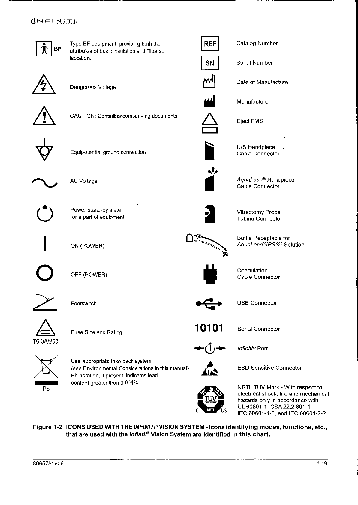
Type
BF
equipment,
attributes
isolation.
Dangerous
CAUTION:
Equipotential
AC
Power
for a part
of
Voltage
stand-by
of
basic
Voltage
Consult
equipment
insulation
accompanying
ground
state
providing
connection
both
and
the
“floated”
documents
REF
DEE
Catalog
Serial
Date
Manufacturer
Eject
U/S
Cable
AquaLase®
Cable
Vitrectomy
Tubing
Number
Number
of
Manufacture
FMS
Handpiece
Connector
Connector
Probe
Connector
Handpiece
Pb
Figure
1-2
ON
(POWER)
OFF
(POWER)
Footswitch
Fuse
Size
Use
appropriate
(see
Environmental
Pb
notation,
content
ICONS
that
are
and
greater
USED
used
Rating
take-back
Considerations
if
present,
than
0.004%.
WITH
THE
with
the
system
indicates
Infinit
lead
/NFINITP
in
this
VISION
Vision
10101
manual)
c
SYSTEM - Icons
System
are
=)
À
pi
©
>
É
7
US
identified
Bottle
Receptacle
AquaLase®/BSS®
Coagulation
Cable
Connector
USB
Connector
Serial
Connector
Infinit®
ESD
NRTL
electrical
hazards
UL
IEC
identifying
in
this
Port
Sensitive
TUV
60601-1,
60601-1-2,
chart.
Connector
Mark - With
shock,
only
in
accordance
CSA
and IEC
modes,
for
Solution
respect
fire
and
mechanical
22.2
601-1,
60601-2-2
functions,
to
with
etc.,
8065751606
Page 28

GNF
INIT
ENHANGED.
FOOTSWITCH
|
[Rer|
2065750405
M
A
ko
DN E NT O TY
REMOTE
219-2384-001
(DG
4
SUNTROL
REV
D
penál
그게
210-2437-003
REV
1
MEINI
ゆ
Alcon
KA
6201
FORFWORTH,
MADE
USA
:
B.
|
|
LAHORATORIES,
SOUTH
FREEWAY
TX
7134-2099
MADE
210.2328-001
:
τ.
IN
ВЕУВ
le
INC,
USA
USA
FOR
APPLICABLE
SCREEN
ON
THE
Dr
:
I
: +.
i
DANCER:
DANGER: - SISQUE
GAUTION:
CAUTION:.
WARNING:
WARNING:
:
RISK
MALEANESTWENCS
"
PRESENCE
GROUNDING
고:
WHEN
©
RECEPTACLE
RISK
CONDUCTIVE
CABLES.
THE
VESSEL
İPS
“CAUTION
POWER
| . МРЕОАМСЕ
FREQUENCY
PATENTS,
PLEASE
MONITOR
DURING
j
OF
EXPLOSION
IF
D'EXPLOSION.
EQUIPMENT
OF
BURNS
UPON
PNEuMATIic
WITH
xd.
BAR,
UTPUT
W
λος
REGUE
NE
D'ANESTHESIQUES
REALIABILITY
IS
CONNECTED
MARKED
AND
FIRE - DO
MATERIALS.
EVIDENCE
SYSTEM
THE
FOLLOWING
Tm
10°
TE
2"
|:
=
di
e
SEE
THE
"ABOUT"
OPERATION.
MET
=
USED
PAS
CAN
HOSPITAL
RENEW
OD
CONTAINS A PRESSURE
C;
V30;3L:
【
- =
COAGULATION
os
I
IN
THE
Pi or
—
EMPLOYER
EN
INFLAMMABLES.
ae
ONLY
BE
ACHIEVED
TO AN
EQUIVALENT|
GRADE.
NOT-USE
NEAR
ELECTRODE
DETERIORATION.
RATINGS:
BIPOLAR
"40
75
5:
NI
구
¡2100-1201
50/60.
Hz
6A
©
οι
csk
c222
220-240V.—
59/60
Alcon
BF a iğ
E201
FORT
*Rog.
@
2005,
2
po.
ot
Ah
Hz
0123
aero
SOUTH
ÅYORTH,
TX75124-2005
U.S.
Pal
2007,2009
‘Alcon
ey
us
SA
ne
FREEWAY
USA
MADE
IN
USA
TIA.
Of.
Inc.
Figure
1.20
1-3
LABELING
illustrated
ON
here.
T6.3A/250.
INFINITF
The
labels
“WARNING:
PROTECTION
REPLACE
-AND:RATING
VISION
on
this
SYSTEM
page
FOR
CONTINUED...
AGAINST
ONLY
WITH
OF
FUSE.
-
Labels
are
intended
RISK'OF
SAME
TYPE
used
for
©
FIRE,
on
the
reference
Infiniti?
only.
Vision
System
8065751606
are
Page 29

40
9
ως
=
mx
u
5
a
8
7
в
5
4
3
2
1
10
LOAD
(OHMS
)
50 75
COAGULATION
200
POWER
GRAPH
~@
-ᾱ- 75%
—Ââ-
BF
me
100%
50%
25%
500
Set
Power
Set
Power.
Sel-Powef
Set
Power.
|
4000
10
(W)
POWER
0
40
35
(V)
30
25
VOLTAGE
20
PEAK
15
10
10
SETTING
20 30
(%)
POWER
40
50 60
ACROSS
75
OHM
70
LOAD
80 90
100
Figure
8065751606
1-4
0
10
SETTING
COAGULATION
setting
in
the
20
(%)
POWER
intended
30
VOLTAGE
OUTPUTS - Set
operating
40
(PEAK)
mode
50
coagulation
in
60
ACROSS
reference
75
OHM
power
to
70 80
LOAD
at
the
figures
above.
90
intended
100
output
control
1.21
Page 30

ÓN
E
TTF
は
THIS
PAGE
INTENTIONALLY
BLANK
1.22
LAST
PAGE
OF
THIS
SECTION
8065751606
Page 31

MN E INTEL
INTRODUCTION
Alcon's
surgical
system
and
communicates
with
on.
This
test
*
Tests
*
Tests
¢
Initializes
When
Setup
the
mode.
Infiniti?
instrument
tones.
Vision
with
An
automatic
System
associated
to
the
performs a variety
the
Central
the
RAM
the
system
If
Processing
and
ROM
system
successfully
the
system
is a multi
microprocessor-controlled
memory
user
via
its
Front
self-test
of
functions including
memory,
completes
fails
the
is
initiated
Unit
(CPU)
and
self-test,
the
and
input/output
Panel
display,
each
the
the
I/O
circuits
self-test,
an
error
message
(I/O)
with
voice
time
system
following:
로
it
automatically
is
displayed.
ophthalmic
circuitry.
The
confirmations,
power
is
goes
turned
into
the
This
section
console
display
and
panel,
VideOverlay
This
is
where
are
shown.
of
the
manual
its
accessories.
IV
pole,
system.
the
The
display
is
broken
All
the
parts
connectors,
second
screens
fluidic
part
for
into
two
of
interface,
of
this
system
major
the
system
section
setup,
parts.
The
first
will
be
described,
footswitch,
describes
surgery,
the
programming,
part
remote
operator
describes
including
control,
and
interface.
and
dialogs
the
the
8065751606
2.1
Page 32

CONSOLE
BN
IN
VISION
ITA.
SYSTEM
Fluidic
Management
inserted
Fluidics
iV
Pole
into
Fluidic
Module
The
fluidics
and
easy
contains
with
Bottle
System
Module
Accessory
module
insertion
all
the
Hanger
(FMS)
Drawers
is
located
of
the
Fluidic
connections
required,
at
the
top
Management
surgery
of
the
can
front
panel.
System
be
The
(FMS),
started
module
and
because
without
Front
Instrument
allows
delay.
|
Front
Display
Touch
Screen
Connector
the
Tray
fast
module
Panel
and
Panel
Caster
Wheels
Figure
communication
surgery.
2-1
(4)
The
Console - The
devices
required
console
by the
contains
surgeon
all
to
the
controls,
perform
Footswitch
Footswitch
cataract
Drawer
connectors,
lens
extraction
and
2.2
8065751606
Page 33

VISION
SYSTEM
Front
Display
The
front
and
surgery.
is
the
Panel
display
user's
main
For
and
Touch
panel
tilts
storage
source
Screen
and
and
transport
of
system
rotates,
allowing
the
control,
front
panel
allowing
easy
maneuverability
folds
down.
fingertip
The
command
during
front
of
system
setup
display
functions.
Front
à
OZi!
Torsional,
and
U/S
Handpiece
Connector
The
connector
self-locking
connectors
bottle
receptacle,
probe.
Coagulation
Connectors
Cable
(2)
NeoSonix®,
Connectors
U/S
for
Symbols
(2)
Panel
panel
is
handpiece
bipolar
and
near
two
the
coagulation
located
to
connectors,
luer
lock
connectors
the
right
of
one
AquaLase®
handpieces,
pneumatic
facilitate
the
fluidics
module.
handpiece
an
AquaLase®/balanced
connectors
handpiece
for
identification.
af,
q
AquaLase®
AquaLase®/BSS®
It
connector,
an
anterior
>
Handpiece
provides
salt
solution
vitrectomy
|
Connector
Bottle
Receptacle
two
two
„i
Dual
Handpiece
Vitrectomy
Connectors
Figure
easy
connection
2-2
The
Front
Connector
of
handpieces
Panel - The
and
consumables.
front
О
connector
panel
allow
quick
and
8065751606
2.3
Page 34

VISION
SYSTEM
Footswitch
The
drawer
identified
requires
insertion
is
used,
Two
is
for
footswitch.
Instrument
Drawer
footswitch
is
used
by
that a plastic
and
remove
footswitch
the
Infiniti?
Tray
Provides a movable
rod
on
the
tray
support
operating
front
IV
Pole
A
bottle
pole.
pressure
of
the
with
of
The
room
Bottle
IV
to
drawer
to
store
its
ribbed
removal
plastic
cable
The
footswitch
tray
arm
cover.
environment:
bed.
The
Hanger
BSS®
or
pole
increase
is
at
and
rubber
insert
of
the
insert
connectors
and
enhanced
instrument
that
allows
The
tray
tray
is
BSS
Plus®
is
used
to
or
decrease.
the
bottom
protect
footpedal
be
placed
enhanced
from
are
Infiniti?
cord
is
tray
for
is
capable
right,
height
irrigating
raise
and
of
the
front
the
footswitch.
surface
in
the
bottom
footswitch.
bottom
of
located
drawer.
behind
footswitch;
also
stored
within
creation
of
left,
adjustable.
lower
in,
the
of a sterile
accommodating a variety
front
and
fluid
is
the
panel.
The
and
two
of
If
the
this
the
and
exits
sterile
field.
rear
hung
from
bottle
height,
When
enhanced
small
the
not
Infiniti®
holes
drawer.
in
use,
in
This
Accurus®/Legacy®
drawer.
right
pouch
of
the
The
left
for
Accurus*/Legacy?
from,
the
drawer.
There
the
is a curved
when
used
of
surgeon
hook
on
causing
positions
as
irrigation
this
footswitch,
its
heel,
allows
easy
footswitch
connector
metal
with
sterile
in
well
as
the
top
of
this
the
Accessory
Two
drawers
Caster
Wheels
Four
for
ease
in
place.
large
when
Handles
Handles
used
to
pushed.
The
system
become
pole.
Handles
instrument.
door
thresholds.
Drawers
caster
of
system
The
being
are
move
damaged.
allow
wheels
mobility,
wheels
moved.
located
the
unit.
must
located
The
unit
storage
support
should
on
the
For
be
moved
Do
not
at
the
should
of
miscellaneous
the
Infiniti®
and
two
wheels
always
sides
greater
be
and
back
safety
CAUTION
carefully,
push
or
pull
rear
and
be
pulled
accessories.
Vision
have a locking
locked
of
and
the
when
control,
otherwise
the
unit
sides
of
the
and
not
System.
lever
the
unit
is
instrument,
the
unit
the
system
by
the
display,
unit
are
pushed,
especially
The
wheels
to
secure
in
use,
and
should
should
be
could
the
provided
over
rotate
the
and
unlocked
always
pulled,
tip
tray,
for
moving
elevator
360°
system
be
not
over
or
the
and
IV
the
and
2.4
8065751606
Page 35

VISION
REAR
PANEL
Power
The
drawer.
switch
e
e
e
Equipotential
For
Cord
Used
Connectors
This
and
connectors,
e
e
e
Module
power
The
is
located
AC
Power
hospital
Main
Fuse
Drawer - Holds
Service
Wrap
to
store
and
module,
outlets
«>
10101
<i>
module
power
contains
module
at
the
Connector - Power
grade
power
Power
Switch - Connects
Ground
Connector
personnel
the
power
CD/DVD
located
used
is
used
USB
Serial
Infiniti?
in
for
electrical
for
Connector - Not
Connector - Used
Port - Not
an
is
located
top
of
the
cord
must
fuse.
Refer
use.
supply
Drive
the
middle
interconnections. A CD/DVD
software
used.
AC
power
at
rear
panel.
cord
be
AC
to
label
cord.
Located
of
the
upgrades
used.
for
connector,
the
from
bottom
AC
of
power
used.
power
on
rear
to
the
to
power
back
on
the
panel,
system.
VideOverlay.
AC
power
the
rear
outlet
supply.
of
system
right
side
contains
switch,
and a fuse
panel. A standby
connects
to
identify
of
‘various
drive,
here.
the
rear
connectors
located
size
panel.
next
A
and
to
power
type.
the
The
USBcomnector
for
use by
Connectors
Equipotential
Fuse
Drawer,
and
AC
Power
Alcon
CD/DVD
and
Ground
Main
Connector
Connector
Power
(*<> ) and
trained
Drive
Switch,
Infinti?
personnel
CAUTION
port ( +-
only.
Failure
)
to
comply
located
will
on
void
the
rear
warranty.
panel
Cord
are
Wrap
8065751606
Figure
nectors,
2-3
The
CD/DVD
Rear
drive,
Panel - The
cord
rear
wrap,
and
panel
standby
contains
power
the
power
switch
module,
(shown
electrical
on
next
con-
page).
2.5
Page 36

Data
Card
A
data
when
Copy/Delete
user
data
Standby
This
freezes
seconds
Inadvertent
Slot
card
(e.g.,
the
user
wants
option
to
copy
data
from a data
Power
Switch
pushbutton
and
is
unresponsive
to
shut
down
pressing
Multi
to
back
from
from
the
card
to
switch
system,
of
Standby
Media
Card
up
the
Custom
Infiniti?
the
Infiniti?
is
used
to
operator
then
switch
(MMC))
or
restore
drop
Vision
Vision
to
turn
re-boot.
WARNING!
when
can
system
list.
The
System
System
secondary
commands,
system
be
inserted
settings.
Copy/Delete
to a data
(restore).
power
ON
press
is
active
will
into
This
is
card
(backup),
and
Standby
cause
ONE
this
data
done
dialog
OFF.
If
switch
unit
card
by
using
allows
or
system
for
to
shut
IMT!
slot
the
the
copy
five
down.
Figure
one-of-two
drawers.
Audio
The
voice
System
change
an
vacuum
are
Audio
Speaker
Multi
Media
Card
2-4
Card
Slot
The
audio
Data
Speaker
audio
speakers
confirmations,
to
communicate
in
the
operating
occluded
adjustable
line.
levels;
via
(2)
in
Right
Side
Panel - The
speakers.
are
The
located
in
conjunction
with
the
mode
and
left
on
each
user.
to
side
Additionally, a varied
the
pitch
the
increases
Custom
as
menus.
right
panel
side
with
multiple
Audible
alert
pitch
the
vacuum
side
has
of
the
tones
the
operator
tone
panel
contains
the
other
console.
tones,
are
of
is
generated
level
increases.
the
speaker
These
to
allow
the
generated
certain
conditions
to
Standby
data
and
Power
card
two
speakers
Infiniti?
to
indicate
audibly
Speaker
Switch
slot
accessory
produce
Vision
a
such
as
indicate
volumes
and
2.6
8065751606
Page 37

ON E INT
FOOTSWITCH
The
Infiniti?
footswitch
footpedal
rather
than a swivel
The
footswitch
footswitch connected.
is
displayed
each
time a switch
is
displayed
Vision
has a footpedal,
swivel
in
in
System
switches.
footpedal.
icon
button
the
center
is
the
icon.
can
utilize
on/off
The
Accurus®/Legacy®
on
the
When
activated.
connected,
of
the
icon,
If a footswitch
two
different
toe
switches
display
the
and a triangular
(horizontal
screen
icon's
is
Alcon
footswitch
is a graphical
footpedal
not
connected,
footswitches.
and
contains
position
arrow
appears
The
Infiniti?
vertical),
representation
no
and
on/off
heel
switches
(0,
1,
2,
next
to
the
footpedal
position
of
or
the
3)
icon
Several
using
aspiration
vitrectomy
on/off,
The
Figure
Table
of
Never
can
functions
the
footswitch.
rate;
to
adjust
footswitch
2-7,
2-1.
To
the
operator's
pick
cause
irreparable
within
OZil®,
cutting,
and
up
and
function
actions
footpedal
program
manual.
or
move
the
system's
The
footpedal
NeoSoniX®,
coagulation
settings,
are
shown
positions/functions
the
footswitch,
the
footswitch
damage.
operating
enables
or
U/S
power.
and
to
in
Figure
see
CAUTION
by
modes
the
surgeon
system power;
The
switches
progress
2-8.
the
the
through
Footpedal
in
each
Custom
cable.
Dropping
are
controlled
to
control
AquaLase®
are
surgical
positions
mode
feature
used
to
of
operation
later
or
kicking
by
the
surgeon
irrigation
system
turn
steps.
are
on
in
flow,
energy,
functions
shown
are
listed
this
the
footswitch
in
in
section
8065751606
Figure
2-5
The
Accurus®/Legacy®
and
Infiniti
Footswitches
2.7
Page 38

ONE
INIT
Plugging
The
footswitch
One
connector
footswitch.
Open
—
mM
Simultaneously
release
3.
Grasping
connectors.
dot
will
NOTE:
connectors
functional.
4.
Acable
securing
cable
slight
5.
Loop
left
are
6.
Shut
in
the
To
the
the
on
the
slide
restraint
restraint
amount
the
or
right
high
the
Footswitch
plugs
is
plug
into
for the
in
footswitch
press a metal
drawer
the
footswitch
The
red
console
in
smoothly.
Only
one
are
used
is
the
cable
over
of
excess
cable
through
slot of
and
low
slots
footswitch
one-of-two
Infiniti®
the
footswitch
drawer.
and
allow
cable
dot
on
the
connector,
footswitch
at
the
same
located
restraint
the
on
and
cable
cable
the
slot
the
cable
management
on
each
drawer.
connectors
footswitch;
follow
drawer
access
extension
to
the
connector,
cable
connector
and
when
the
connector
time,
the
back
place
and
secure
exists
in
side
of
the
between
the
back
of
the
only
behind
the
other
the
directions
latch
footswitch
plug
the
must
connector
is
intended
the
Infiniti?
the
drawer.
cable
through
it
with
the
the
connector
of
the
system
in
drawer.
the
footswitch
is
for
the
below.
on
each
cable
cable
into
be
in
is
in
to
be
Loosen‘the
its
two
screws.
drawer,
the
front
drawer.
Accurus®/Legacy®
of
two
hinges
connectors.
one
of
the
two
alignment
the
used
footswitch
center.
and
then
of
with
correct
position
at a time.
connector
two
screws
Replace
Ensure
the
restraint.
route
it
through
the
drawer.
the
that
to
red
If
both
the
a
There
it
is
the
Figure
2-6
Footswitch
Cable
Routing
footswitch
cable
cable
connectors
restraint
footswitch
==
footswitch
— — drawer
(2)
cable
drawer
extension
management
latch
system
2.8
8065751606
Page 39

ONFINIT
!
VISION
STEM
Footpedal
fixed
Figure
Control
Depending
footpedal
coagulation).
range
2-7
on
is
directly
Diagram
the
surgery
control
With
proportional
of a surgical
linear
of
Footpedal
step,
the
footpedal
to
the
Positions
user
may
parameter
control,
parameter
the
一 一 一
ーーーーーーーーーー
have
the
(1.e.,
angle
output.
一
option
aspiration,
of
The
POSITION
POSITION
ー
A
to
select
vacuum,
depression
parameter
0
1
>>>
POSITION
2
ー
ペーーーーー
POSITION
テ
ーー 一 ~«——
resting
detent
detent
3
full
linear
power,
within
output
position
1
2
footpedal
depression
or
the
is
pedal
0
Table
2-1
several
of
the
surgical
operation
resting
Resting
Continuous
Resting
Continuous
Resting
Continuous
Resting
Continuous
Table
of
functions.
and
type
position
Resting
Footpedal
of
into
Irrigation
Irrigation
Irrigation
Irrigation
Irrigation
Irrigation
This
irrigation
its
active
Irrigation
Irrigation
Positions - The
table
selected.
positions.
shows
Irrigation/Aspiration | Irrigation/Aspiration
Irrigation/Aspiration
Irrigation/Aspiration
Irrigation/Aspiration
Irrigation/Aspiration
Irrigation/Aspiration
Irrigation/Cutting
Irrigation/Cutting
Coagulation
footpedal
the
functions
As
the
is
used
controlled,
footpedal
by
is
depressed
*
Phaco
Power
*
NeoSonix
*
Torsional
*
AquaLase
Irrigation/Aspiration
*
Phaco
*
NeoSonix
*
Torsional
*
AquaLase
Amplitude
Amplitude
Magnitude
Power
Amplitude
Amplitude
Magnitude
Irrigation/Aspiration
Cutting
Irrigation/Aspiration
Cutting
Irrigation/Cutting
Aspiration
Irrigation/Cutting
Aspiration
Power
the
surgeon
dependent
to
it
travels
control
on
mode
from
8065751606
2.9
Page 40

VISION SYSTEM
at
the
very
start
of
the
value
specified
parameter
detents
the
position
to
The
by
identify
operator
into
do
so.
footswitch's
pressing
described
at
output
the
when
the
the
Footswitch
later
in
treadle
the
end
is
fixed
transition
slightly
next.
Detents
Buttons
this
section
range,
of
the
at
its
from
more
and
Treadle
Button
of
and
treadle
limit
value
one
pressure
can
also
in
the
the
manual.
the
parameter
range.
With
throughout
footpedal
is
be
accompanied
position
required
adjustments
Main
Window.
output
fixed
footpedal
the
treadle
to
to
press
by
vibration
are
programmable
The
is
equal
to
control,
range.
another,
the
and
footpedal
if
programmed
and
Footswitch
the
limit
the
Footpedal
are
felt
from
one
are
available
Button
is
by
Switch
Control
The
footswitch
functions.
horizontally
shifted
that
operate
down.
Switch
selections
default
mutually
a
function
designation.
Grade+,
If
the
switches
switches
operation,
if a switch
not
available
The
Jnfiniti®
and
left
or
right.
horizontally
functions
on
the
action:
Reflux.
exclusive,
already
Choices
Grade-,
footpedal
are
mutually
are
disengaged.
certain
is
permitted
when
has
six
switches
footswitch
vertically,
The
Accurus®
and
are
programmable
display.
The
and
The
must
designated
are
Cont.
Grade+/-,
is
not
depressed,
exclusive
If
switches
to
be
the
treadle
that
can
has
and
footpedal
/Legacy®
vertically,
by
left
horizonal
other
five
switches
be
programmed
to
another
Irr.,
Reflux,
Vit
Cutter,
any
switch
and
cannot
the
footpedal
may
or
may
engaged
is
depressed,
be
programmed
left
and
switches
footswitch
and
heel
pressing
switch
switch,
Irr.
Video
Overlay,
may
be
is
depressed,
not
be
with
the
and
right
toe
that
switches
the
footswitch
is
are
listed
by
the
user.
the
other
Up,
Irr.
be
engaged;
engaged
allowed
treadle
the
command
to
control
switches
activate
has
left
that
activate
icon
the
only
switch
as
None,
When a switch
switch
Down,
and
Step+,
None.
however,
until
all
depending
to
engage.
depressed,
will
various
that
operate
when
the
and
right
toe
when
and
making
with a factory
their
functions
is
is
given a None
Step-,
the
other
assigned
on
the
mode
Furthermore,
some
functions
not
be
performed.
surgical
pedal
is
switches
pressed
given
Step+/-,
assigned
of
even
are
are
8065751606
Page 41

ONE
INIT
VISION
SYSTE
Pressing
to
adjust
medium
Left
left
down
this
the
(2),
or
toe
for
one
for
button
toe
switch
wide
switch
function,
another.
allows
the
for a narrow
(1)
foot.
is
pressed
and
operator
(3),
Footpedal
toggles
footswitch
for
switches.
the
same
swiveled
utilizes
left
The
heel
functions.
Pressing
to
for a short
size.
different
and
right
Accurus?
switches
this
adjust
the
(S),
It
can
balance
The
plugs
tension
are
Right
one
button
heel
medium
also
be
footswitch's
into
this
knob
also
on
this
toe
switch
function,
and
allows
rest
forward
adjusted
feel.
and
(M),
removeable
end.
and
carrying
end.
is
pressed
down
the
operator
or
or
long
to
attain
The
footpedal
for
backward
(L)
a
cable
handle
right
for
another.
foot
Left
Horizontal/Vertical
Tension
Left
Heel
Adjustment
Switch
Switch
Knob
mm
Footpedal
Right
Right
Horizontal/Vertical
Heel
Switch
Switch
8065751606
Figure
2-8
Footswitches
Infiniti?
Accurus®/Legacy®
Used
with
the
Infiniti?
footswitch
with
its
switch
footswitch.
actions
Vision
System - Shown
identified.
Shown
at
the
below
top
is
is
the
the
2.11
Page 42

VISION
SYSTEM
The
following
treadle
the
be
e
depressed.
treadle
engaged
Continuous
When a switch
irrigation
is
available
Coagulation
¢
Reflux
The
default
pressure
In
all
cases,
available
sections
is
depressed,
with
the
Irrigation
indicate
If
it
is
treadle
On/Off
assigned
status
immediately
when
the
footpedal
step.
reflux
can
reflux
pressure
be
increased
is
not
in a Coagulation
whether
permitted,
the
function
depressed.
to
Continuous
activates/deactivates.
is
is
equal
using
the
available
step.
and
must
in
any
to
the
Reflux
when
each
switch
the
user
intends
be
assigned
Irrigation
position,
current
Offset
the
control
footpedal
function
to
to a switch
On/Off
Continuous
but
is
bottle
height
is
depressed,
is
permitted
control
is
toggled,
not
available
pressure.
in
the
Custom/Doctor
with
that
function
that
is
permitted
the
continuous
irrigation
toggling
in
a
The
and
is
not
,
the
when
to
reflux
menu.
*
Irrigation
A
switch
pressed
If
the
Up,
may
and
immediately
switch
is
continuously
function
*
Step
A
switch
is
available
Advance,
may
advance/back
excluded
If
step
previous
is
assigned
less
back
from
advance
step
to a switch,
than
1/2
function
Irrigation
be
assigned
pressed
up
or
down
in
Step
Back,
be
assigned
(Step
+/-).The
this
stepping
or
step
to
the
current
second.
will
If
be
Down
as
irrigation
released,
and
held
until
the
all
steps but
Step
as
step
Setup,
sequence.
back
is
assigned,
step
then
step
the
switch
activated.
up
or
the
IV
pole
for
more
than
switch
is
released.
coagulation,
Advance/Back
advance
(Step
Coagulation,
when
is
selected
advance
is
pressed
in
will be
irrigation
down.
position
1/2
second,
Control
and
in
+),
step
and
Anterior
the
switch
the
surgery
activated
for
more
than
will
increment
the
all
footpedal
back
is
pressed,
menu.
if
1/2
When
the
up
IV
pole
will
of
this
irrigation
positions.
(Step
-),
Vitrectomy
the
If
step
the
switch
second,
switch
or
down.
is
move
or
step
steps
are
next
or
advance/back
is
pressed
then
the
for
step
8065751606
Page 43

¢
Cataract
A
switch
decrease
control
of
available
If
cataract
pressed,
cataract
will
is
pressed
will
If
the
the
grade
be
activated
be
activated.
highest
selected,
grade
is
currently
grade
will
Grade
may
(Grade
the
whether
grade
Increase,
be
assigned
-),
cataract
or
increase
next
or
or
not
previous
increase/decrease
if
the
for
more
than
cataract
the
lowest
cataract
selected
be
selected.
Decrease,
as
cataract
cataract
grade
is
the
footswitch
or
cataract
cataract
switch
200
milliseconds,
grade
is
grade
and
Increase/Decrease
grade
grade
increase/decrease
only
available
grade
grade
is
assigned
is
pressed
currently
will
cataract
increase
in
treadle
is
decrease
to
the
to a switch,
for
less
then
selected,
be
selected.
grade
decrease
(Grade
(Grade
phaco
and
depressed.
is
assigned,
current
then
than
200
the
cataract
and
cataract
Similarly,
is
+),
cataract
+/-).
Footswitch
AquaLase®
cataract
cataract
when
grade
steps,
the
grade
milliseconds.
grade
decrease
grade
increase
if
the
lowest
selected,
the
highest
grade
and
switch
is
selected.
increase
If
the
switch
function
is
cataract
cataract
is
is
If
When a new
specified
e
Vit
Cutter
A
switch
switch
all
other
enabled
functionality
cut.
The
function
disabled,
e
VideOverlay
cataract
for
the
On/Off
may
is
an
exception).
times
when
Vit
Cutter
takes
the
message
be
in
When a switch
(including
is
available
activation
Alcon
in
is
permitted
grade
new
cataract
assigned
the
designated
the
Vit
step
footpedal
switch
effect
immediately.
On/Off
assigned
logo)
any
footpedal
is
selected,
grade.
to
The
is
Vit
enable
button
selected.
and
Cutter
does
positions 2 and 3 is
may
be
pressed
When
“Vit
Cutter
to
VideOverlay
is
toggled
with
Disabled”
on/off
position
the
pedal
when
surgical
disable
function
parameters
the
is
nothing.
When
the
Vit
unchanged,
in
footpedal
the
current
is
displayed
On/Off
on
the
it
is
video
is
assigned
depressed.
will
Vit
Cutter
available
The
Cutter
Vit
only
Cutter
is
but
positions
step
is
Vit,
in
the
toggled,
the
display.
to a switch
be
updated
(the
left
horizontal
in
the
is
automatically
disabled,
the Vit
and
1,
2,
the
Cutter
or
the
Surgery
video
overlay
Control
of
in
which
with
Vit
step;
I/A
does
3,
and
Vit
Cutter
Screen.
output
this
function
those
at
not
the
is
8065751606
2.13
Page 44

REMOTE
CONTROL
The
remote
ways.
support cover
Assistant
Nurse
custom
control.
It
Do
can
access
can
operate
user
not
sterilize
control
be
laid
supplied
to
the
setup
features
for
the
in
its
in
the
controls
remote
the
remote
Infiniti“
tray
assembly
the
disposable
from
control
are
functions
CAUTION
control
system
is
wireless
receptacle
pak;
this
the
sterile
in a non-sterile
which
as
it
will
field.
are
and
can
be
and
operated
offers
the
Scrub
Alternatively,
manner.
not
accessible
damage
Programmability
the
used
under
Nurse
the
from
unit.
ONE
in
the
Circulating
the
INIT!
one
of
sterile
or
Sterile
remote
two
tray
and
2.14
Figure
2-9
The
Remote
receptacle
cover
is
then
Control - The
and
allows
draped
over
remote
rotation
the
control
in
any
remote
fits
securely
orientation.
and
tray.
The
in
its
sterile
tray
tray
assembly
support
8065751606
Page 45

VISION
SYSTEM
Remote
The
following
Control
sections
a
remote
appropriate.
The
remote
of
the
remote
Vision
status/surgery
menu.
remote.
e
Irrigation
The
Irrigation
touchscreen.
rapidly
irrigation
valid
when
will
control
control
System
The
Adjust
Control
up
or
control
any
Keys
and
Buttons
describes
describe
key
the
the
or
button
is
divided
function
approximately
display
control
screen.
window,
button
and
Up/Down
Control
Each
up/down
individual
down, a key
keys
are
dialog
is
displayed.
remote
of
is
pressed, a valid
into
corresponds
The
three
2)
the
items
Keys
keys
press
is
pressed
only
valid
control
each,
three
sections
sections
main
in
the
Adjust
on
the
raises
and
in
the
held
the
keys
and
and
indicate
or
to
its
associated
of
window,
bar
remote
IV
pole 1 cmH20
until
Setup
buttons.
when
invalid
from
top
the
display
and
are
function
the
desired
and
Surgery
The
they
key
tone
to
bottom.
section
screen
3)
the
setup
not
accessible
as
they
up
height
screens,
following
are
valid.
When
is
generated
Each
section
of
the
Infiniti®
are
1)
the
steps/surgery
with
the
do on
the
or
down.
is
To
reached.
and
are
as
setup
move
The
not
Parameter
Parameter
up / down
Forward / Back
arrow
Selection
Value
keys
keys
button
Adjustment
Irrigation
up / down
Control
keys
BOTTOM
Enter
key
Cataract
Backlight
Grade
button
key
(2)
8065751606
Figure
2-10
The
Remote
Control
Keys
2.15
Page 46

e
Cataract
The
surgery
pressed
grade
The
elapsed
selected
cataract
¢
Parameter
The
select
With
parameter.
depressed,
*
Parameter
The
Window
linear/fixed
Selection
Value
Grade
Cataract
steps,
it
cycles
1.
The
first
press
from
grade.
grade,
Selection
Parameter
Coag
and
this
button
This
but
Value
Parameter
that
toggle
button, a yellow
Adjustment
Key
Grade
Default
the
have
key
and
is
not
the
cataract
of
the
last
Each
with
voice
Selection
Vit
steps.
the
user
button
is
invalid
Adjustment
Value
adjustment
buttons.
up/down
is
only
valid
valid
when
grade
Grade
Cataract
subsequent
can
be
Grade
press,
simply
confirmation
Button
button
can
is
valid
when a dialog
Adjustment
is
The
current
navigate
when
Up/Down
arrows
When a surgical
border
keys
in
the
any
dialog
upward
programmed
key,
or
invokes
press
of
the
of
used
to
selection
up,
the
footpedal
is
displayed.
Keys
up/down
(1.e.,
indicates
can
then
setup
screen
is
displayed.
until
it
in
the
first
the
voice
key
within
the
grade.
select
parameters
is
down,
be
left,
keys
affect
power,
parameter
that
the
used
and
during
Each
reaches
the
indicated with a yellow
and/or a footswitch
vacuum,
item
to
4,
and
Custom/Doctor/General
press
after
confirmation
five
seconds
for
and
right
settings
aspiration)
is
selected
is
selected;
adjust
its
lens
removal
time
this
then
begins
five
seconds
of
the
selects
adjustment,
to
select
È
in
the
via
value.
the
button
Surgery
and
the
the
Parameter
VISION
key
is
again
menu.
have
currently
the
next
and
to
border.
desired
is
up
Control
the
Parameter
SYETE
at
or
If a linear/fixed
up/down
e
Forward/Back
The
buttons
using
The
If
Coagulation
select
vitrectomy
the
Setup
In
the
button,
keys
Forward/Back
and
the
Forward
the
system
Screen.
Setup
the
toggle
can
Arrow
the
Surgery
Forward
key
or
next
or
step
selected.
will
select
Screen,
button
button
be
pressed
Arrow
key
or
and
Back
Anterior
previous
the
when a Forward/Back
will
be
is
selected,
to
toggle
Keys
keys
are
used
Menu
steps.
Back
key
on
key
do
not
Vitrectomy
step
relative
Additionally,
Setup
button;
highlighted,
the
In
the
wrap
is
if
but
either
value
to
move
the
Surgery
remote,
the
to
the
the
the
Enter
key
the
of
the
parameter
between
left
and
screens,
the
step
around.
current
Back
step, a Forward/Back
last
non-coagulation
key
scrolls
key
must
is
used
to
Enter
key
linear
right
through
when a step
is
immediately
all
be
pressed
move
must
be
value
and
to a Setup
pressed
and
the
fixed.
way
adjustment
the
is
non-anterior
to
invoke
to
Setup
selected
selected.
key
to
Step
Step
will
the
left,
the
activate
2.16
8065751606
Page 47

VISION
$YSTN
the
button.
sequence,
The
Forward
button
*
Enter
The
Enter
it
has
when
(e.g.
screen
between
selected
when
If
the
Forward
the
system
key
(e.g.,
OK,
Key
key
is
been
selected
the
Setup
prime
FMS,
with
the
Irrigation/Continuous
with
the
the
Metrics
will
and
Back
Cancel,
only
valid
with
the
button
Forward/Back
has
fill,
test
Parameter
window
key
is
pressed
skip
to
the
vacuum
key
can
also
Save,
etc.).
to
do
the
following:
Parameter
been
selected
handpiece.)
key,
Irrigation
Selection
is
selected
when
4)
invoke
button,
with
during
be
Selection
with
when
the
check.
used
1)
the
the
function
the
highlighted
the
and
the
Parameter
button,
draw
fluid
in
an
information
select
Back
Irrigation
6)
the
2)
key,
has
select
Selection
portion
dialog
Coag
or
Ant
go
to
the
Setup
3)
invoke a setup
been
selected
button
and
in
dialogs,
Controls
Reset
Metrics
button.
of
the
to
Vit
Screen
in
window
priming
select
step
the
a
after
function
Setup
5)
toggle
is
to
zero
Remote
When
will
will
changing
A
battery
batteries,
screwdriver
battery
important
(see
on
the
turn
not
properly
following
Control
batteries
appear
disappear
Figure
side
off
Batteries
below
after
batteries,
holder
loosen
and
positions
that
2-11).To
of
the
after a few
inserted
local
in
the
remote
the
irrigation
new
select
inside
two
captive
remove
are
identified
rubber
buttons
check
remote
seconds.
into
governing
control
controls
batteries
remote
the
cover.
and
slots,
are
control
remote
screws
Replace
inside
slide
correct
verify
If
illuminated
so
ordinances
are
low,
the
each
time a remote
installed
holds
on
each
into
installation
that
you
and
and a remote
channel
three
the
rear
old
batteries
battery
slots
in
the
remote
buttons
must
repeat
recycling
(3)
of
status
message
as
instucted
AAA
cover
other
batteries,
(LR3)
with a standard
and
slot).
When
half
control
don't
procedure.
plans.
“Remote
key
is
pressed.
control
replace
of
press a Backlight
buttons
turn
key
on
next
batteries.
cover
closing
remote
off,
rubber
Dispose
is
page.
slotted
cover
without
illuminate,
Battery
The
message
pressed.
To
replace
(correct
it
is
binding
button
then
buttons
of
batteries
Low”
After
are
8065751606
Figure
2-11
Proper
Orientation
of
Two
Halves
of
Remote
Control
2.17
Page 48

OSEA
Select
Remote
The
remote
allows
operating
A.
For
channel
The
Custom/System
A,B,C, & D.
control.
To
select a remote
1.
Press
2.
Press
3.
Press
dialog
4.
Hold
press
Simultaneously
5.
Press
at
6.
Press
Control
control
four
remote
in
the
proper
9:00, B at
as
the
Set
the
the
Custom
the
System
the
Remote
(see
the
remote
its
parameter
the
parameter
the
Enter
remote
remote.
This
remote
Figure
Channel
can
be
controls
same
room
operation,
Settings
selection
channel
channel
key
to
key
to
Channel
2-12).
control
value
release
selection
12:00, C at
button
on
configured
to
independently
or
area.
Remote
the
Infiniti?
window
must
correspond
as
instructed
on
the
Infiniti?
activate
bring
in
front
adjustment
the
buttons.
3:00,
the
its
up
the
button
of
button
and D at
remote
to
operate
control
controls
Vision
allows
the
to
below.
Vision
drop-down
System
to
bring
up
the
Infiniti®
up/down
corresponding
6:00
(see
Figure
on
one-of-four
four
are
factory
System
selection
the
channel
System:
menu.
Settings
the
Remote
display
keys
(labeled
to
on
the
screen).
2-10),
channels.
Infiniti?
preset
must
be
of
four
remote
selection
window.
Control
screen
‘1
the
new
then
press
This
Vision
and
Save
Systems
to
channel
set
to
the
receive
on
the
remote
Settings
simultaneously
822
on
the
channel
(labeled
on
the
feature
same
codes:
screen).
A
screen.
No
additional
channel
NOTE:
controls
is
steps
stored
If
necessary
and
the
Do
not
are
needed
per
unit.
to
distinguish
units
with
sterilize
the
once
unique
remote
the
remote
between
labels.
CAUTION
control
channel
remote
as
it
will
is
set,
and
controls,
damage
only
one
identify
the
the
unit.
remote
remote
2.18
Figure
2-12
The
Remote
Control
Settings
Dialog
8065751606
Page 49

VISION
SYSTE
HANDPIECES,
Phaco
ywrasoni
Soscnation
TIPS,
Different
steps
and/or
are
available.
appropriate
Following
sleeves
Ultrasound
Alcon's
functions
inflate
eye.
с
AND
INFUSION
handpieces,
functions. A full
Please
handpieces,
is a general
used
to
perform
Handpieces
phaco
the
handpieces
of
the
lens
anterior
tips,
and
contact
tips,
description
lens
integrate
extraction
chamber,
SLEEVES
infusion
selection
your
Alcon
and
infusion
of
removal
irrigation,
step
emulsify
sleeves
of
handpieces,
representative
sleeves
the
various
procedures.
aspiration
enable
the
the
lens,
surgeon
and
are
required
along
for
for
your
specific
handpieces,
and
to
simultaneously
aspirate
for
different
with
tip
information
procedural
styles
regarding
technique
tips,
and
infusion
emulsification.
the
lens
material
and
sizes
the
and
needs.
The
three
maintain
from
the
or
Figure
Figure
2-13
2-14
OZif®
ye
aso?
d
Infiniti?
Torsional
Mat,
alio,
&
m
NeoSoniX*?
LE
Handpiece
LE
Handpiece
Figure
8065751606
2-15
Infiniti
Ultrasonic
(U/S)
Handpiece
2.19
Page 50

VISION
SYSTEM
These
the
‧
e
e
Do
is
use.
handpieces
ultrasonic
OZil®
Torsional
functions
oscillations.
best
performance
Alcon
Infiniti®
applications
mm
TurboSonics®
Infiniti?
functions
This
handpiece
not
test
immersed
Irreparable
reguire
tip,
and
of
the
This
representative.
Ultrasonic
on
the
NeoSoniX?
of
the
uses
or
operate
in
BSS®
damage
no
the
infusion
Handpiece - The
ultrasonic
handpiece
of
OZil®
(U/S)
Infiniti?
tips,
Handpiece - The
ultrasonic
the
U/S,
sterile
disassembly
sleeve
OZ
handpiece,
uses
many
torsional
Handpiece - This
Vision
including
handpiece,
System
flared
NeoSonix®
handpiece,
same
tips
as
the
CAUTIONS
OZil®
torsional,
irrigating
to
the
handpiece
solution
other
than
with
bubble
torsional
and
in
addition
of
the
same
handpiece
with
and/or
and
in
addition
U/S
handpiece.
or
NeoSoniX®
and
tip
removal
suppression
handpiece
provides
tips
use
tips
is
1.1
mm
ABS*®
tips.
handpiece
provides
or
distilled
can
result
of
the
disposable
insert.
integrates
ultrasonic
as
the
U/S
handpiece;
recommended
used
for
ultrasonic
TurboSonics*
integrates
sonic
Pa
handpieces
water
if
run
or
dry.
tubing,
all
for
by
your
tips
or
0.9
all
oscillations.
unless
is
the
in
surgical
tip
Ensure
U/S,
OZil®
in
premature
Use
or
use
may
operator.
Use
of
irrigation
excessive
that
test
chamber
torsional,
tip
of
an
ultrasonic
of a handpiece
result
of
the
in
OZi/®
flow
heating
or
NeoSoniX®
failure
handpiece
patient
torsional,
and/or
and
is
filled
and
breakage.
repaired
injury,
including
NeoSonix®,
in
the
presence
potential
with
BSS®
handpieces.
WARNINGS!
other
than
without
thermal
Alcon
potential
U/S,
of
sterile
the
or
reduced
injury
irrigating
Tuning a handpiece
OZi/®
torsional,
authorization,
shock
AquaLase®
or
lost
to
adjacent
solution
NeoSonixX®,
is
not
hazard
handpiece
aspiration
eye
to
tissues.
before
dry
may
or
permitted,
patient
in
flow
the
and/or
absence
can
cause
tuning
result
U/S,
and
2.20
8065751606
Page 51

VISION
SYSTEM
TurboSonics®
U/S
tips
are
torsional,
assisting
by
Various
Each
surgery
or
disabled
e
the
surgeon,
doctor
screen
1.1mm
in
U/S
TurboSonics®
e
0.9mm
a
smaller
*
Mackool**
over
the
provides
*
Aspiration
portion
during
Use
0.9
infusion
specially
create a patient
Family
made
of
U/S,
or
NeoSonix®
its
removal
various
tip
styles
selects
for
his
from
the
U/S
Tips - The
tips.
U/S
Tips - The
incision.
U/S
main
part
additional
Bypass
of
the
tip’s
occlusion
mm
tips
sleeves.
adjusted
hazard.
of
Tips
medical
are
the
selected
Custom
grade
handpiece
by
aspiration.
styles
of
tips
color
coded.
Ozil®,
U/S,
handpiece.
Copy/Delete
standard
They
are
designed
0.9
mm
They
are
designed
Tips - The
of
thermal
the
tip
Mackool**
shaft.
and
System - The
wall.
This helps
of
the
tip’s
main
with
0.9
mm
Mismatch
for a particular
of
titanium
to
deliver
Depending
and
tip
and
NeoSoniX®
The
feature.
ultrasonic
for
ultrasonic
for
ultrasonic
This
necessary
fluidic
ABS®
advantages.
tip
to
maintain
port.
WARNINGS!
infusion
consumable
combination
alloy,
and
are
mechanical
on
the
needs
bevels
use
use
tips
tips
only
tips
only
are
available
tips
offered
offered
are
the
with
are
designed
with
tips
contain a polymer
part
contains a small
flow
through
sleeves.
components
Use
of
consumable
attached
energy
and
(see
at
the
for
each
original
1.1
mm
to
allow
0.9
mm
of
the
Mackool**
hole
the
1.1
mm
and
use
to
an
Ozil®
to
the
technique
Figure
top
of
the
doctor
1.1
are
mm
infusion
entry
infusion
,
in
the
distal
system
tips
with
of
settings
components
lens,
preferred
2-16).
enabled
sleeves.
through
sleeves.
tubing
tip
even
1.1
mm
not
may
Read
Standard
with
tip
the
round
shape.
U/S
The
small
The
Aspiration
a
small
hole
small
ES
Tapered
of
inner
while
tapered
flared
as a straight
the
Tip - The
0.9
and
the
distal
ABS®
tip,
and
mm
outer
all
Tip - The
shaft
0.9
mm
hole
Bypass
in
the
distal
hole
tapered
tip
and
diameters
end
tip
has
the
same
tip.
package
1.1
mm
is
the
original,
has a smaller
JN
System - The
portion
JN
ASE
ABS®
the
flared
is
equivalent
is
comparable
the
improved
aspiration
label
material
TurboSonics®
classical
of
the
tip
ABS®
flow
U/S
diameter
ABS®
tip's
wall.
is a combination
tip.
The
to
straight
to
flared
tips.
holding
force
characteristics
printed
tip
shaft.
tip
contains
shaft
tips,
The
of
on
the
consumable
Kelman®
which
to
efficiency.
during
Tip - The
generates
the
conventional
In
the
surgical
small
addition,
Flared
ABS®
port,
providing
middle
improving
anterior
also
have
enhance
polymer
a
Mackool**
ultrasonic
main
part
Tip - The
increased
of
the
shaft,
occlusion
chamber,
the
Aspiration
performance.
tubing
Series
tip
contains a polymer
of
the
paks
Kelman®
transverse
iongitudinal
the
procedure.
hole
—
flared
thus
allowing
breaks
following
Bypass
U/S
Tip - The
tip
shaft.
prior
tip
ultrasound
motion,
bend
allows
tip
holding
by
reducing
occlusion
to
their
has a bent
motion,
to
enhance
better
has a larger
force.
They
smaller
incisions
outflow
breaks.
System
feature,
Mackooř*
tubing
over
use.
shaft
in
addition
cutting
visibility
proximal
narrow
in
and
from
the
Flared
tips
to
further
the
the
Figure
8065751606
2-16
TurboSonics®
U/S,
and
NeoSoniX®
Tips - Shown
handpieces.
here
are
samples
of
U/S
tips
used
with
the
OZiF
torsional,
2.21
Page 52

VISION
SYSTEM
AquaLase®
The
AguaLase®
perform
chamber
Each
doctor
selected
Custom
e
1.1
e
1.1
for
Figure
2-17
AquaLase®
Liquefaction
handpiece
liquefaction
and
aspirating
selects
the
handpiece.
Copy/Delete
mm
Liquefaction
MI
Liquefaction
small
incision
Liquefaction
Handpiece
utilizes
on
the
lens,
the
lens
AguaLase®
The
tips
feature.
Tip - Standard
Tip - Micro
surgery.
Handpiece
warmed
while
material
tips
offered
high
at
the
from
offered
for
each
tip
used
Incision
energy
same
time
the
eye.
at
the
doctor
with
tip
used
rapid
irrigating
top
of
are
enabled
1.1
mm
with
pulses
the
surgery
or
infusion
1.1
mm
of
fluid
the
anterior
screen
disabled
sleeves.
infusion
to
for
his
from
the
sleeves
Figure
MicroSmooth®
Infusion
chamber
the
some
torsional,
Infusion
descriptions).
INFUSION
2-18
Infiniti?
Infusion
sleeves
of
Infiniti?
Ultraflow™ * I/A
and
sleeves
SLEEVE
U/S
Handpiece
cover
the
eye
U/S,
Ozil®
NeoSoniX®
must
Infiniti®
Sleeves
the
tip
during
surgery
torsional,
handpieces.
handpieces
be
correctly
paks
contain
BUBBLE
shown
of
the
NeoSoniX®,
SUPPRESSION
with
Infusion
handpiece
(see
Figure
Infusion
require a BSI
matched
only
to
MicroSmooth®
INSERT
Sleeve
to
provide
2-18).
and
AquaLase®
sleeves
(bubble
the
specific
(BSI)
and
irrigation
Infusion
used
with
suppression
tip
infusion
Bubble
to
the
sleeves
handpieces,
are
Infiniti?
type
(see
sleeves.
Suppression
anterior
used
and
with
U/S,
Ozil®
insert).
the
following
Insert
with
2.22
8065751606
Page 53

VISION
SYSTEM
Depending
infusion
*
*
*
sleeves
Standard
Standard
tips;
and
MicroSmooth®
shaft
diameter
high
infusion
to
irrigation
anterior
be
used with
tips.
MicroSmooth®
diameter
infusion
available
used
with
on
the
needs
are
available.
MicroSmooth®
infusion
0.9
flow
chamber.
than
sleeves
in
1.1
0.9
sleeves
mm
(purple),
High
than
sleeves
resulting
High
1.1
mm
Ultra
original
is
mm
mm
tips.
and
technique
Infusion
are
to
be
Infusion
original
is
tips;
Infusion
compatible
(green),
infusion
compatible
from
infusion
and
infusion
to
preferred
Sleeves - These
available
used
with
Sleeves - High
sleeves.
with a larger
this
larger
sleeves
semi-transparent
Sleeves - Ultra
sleeves.
with a smaller
be
used
WARNINGS!
in
1.1
0.9
shaft
are
available
The
with
by
mm
mm
infusion
The
infusion
smaller
incision.
1.1
the
surgeon,
are
the
(blue),
tips.
sleeves
larger
incision.
diameter
purple,
mm
shaft
in
semi-transparent
to
sleeves
shaft
Ultra
tips;
various
original
to
be
(HIS)
diameter
Reduced
creates a more
be
used
have a smaller
diameter
infusion
and
0.9
styles
infusion
used
with
have a larger
resistance
with
of
the
sleeves
mm
of
sleeves.
1.1
mm
of
the
stable
blue,
0.9
mm
shaft
Ultra
are
(rose),
to
to
be
Use
1.1
tips
Mismatch
particular
Read
0.9
mm
mm
liquefaction
and
infusion
all
package
U/S
tips
exclusively
tips
exclusively
sleeves
of
consumable components
combination
labelling
may
of
consumable
on
with
create
the
consumable
0.9
mm
with
1.1
potentially
and
use
components
infusion
mm
infusion
hazardous
of
settings
paks
sleeves.
sleeves.
fluidic
not
specially
may
create a patient
prior
to
their
Use
1.1
mm
Mismatching
imbalances.
adjusted
use.
U/S
and
U/S
fora
hazard.
8065751606
2.23
Page 54

VISION
ATSTE
Ultraflow™*
The
irrigation
the
band
of
the
Ultraflow™ * I/A
e
Ultraflow* * IT
of a handpiece
adapter
*
Ultraflow™ * I/A
TurboSonics®
handpiece
* = Ultraflow™ * SP
SP
infusion
Handpieces
Ultraflow™ * handpiece
while
markings
Ultraflow™ * IT
consists
and
removing
on
the
and
handpieces
Handpiece
body
that
or
infusion
with
of a single-piece
sleeve.
sleeve
Handpiece
silicone
threaded
I/A
Handpiece
Various
Tips
is
used
cortical
tips
SP
infusion
material
that
identify
handpieces
and
tips
and
Interchangeable
accepts
as
they
and
sleeves
tip
adapter.
handpiece
tip
configurations
in
I/A
mode
to
maintain
via
aspiration.
size
of
tip
also
use
infusion
are
available:
Tips - The
interchangeable
contain a built-in
Threaded
(Single-Piece
can
with
are
Tip
be
Adapter - Reusable
used
with
aspiration
available.
WARNINGS!
chamber
(See
Figure
aperture.)
tips.
metal
with
fixed
Some
sleeves.
Ultraflow™ * IT
These
infusion
the
Ultraflow™ * I/A
tips) - The
tip
and a built-in
pressure
2-20
configurations
The
following
tips
do
not
sleeve.
I/A
tips
Ultraflow™
with
and
note
consists
require
with
|
metal
an
*
Use
of
Alcon
with
the
may
cause a shallowing
Exceeding
may
cause
posterior
ПА
tips
non-Alcon
surgical
Infiniti?
the
anterior
capsule.
are
not
surgical
specifications,
Vision
recommended
to
be
reusable
System,
or
chamber
used
collapsing
with
or
disposable
or
use
of
may
result
of
level
of
100
shallowing
U/S,
NeoSonix®,
an
Alcon
in a fluidic
the
anterior
mmHg
and/or
I/A
handpieces
handpiece
imbalance.
chamber.
with a 0.5
incarceration
or
OZiF
torsional
that
not
specified
mm
or
or
handpieces.
do
not
This,
larger
tearing
for
in
I/A
of
meet
use
turn,
tip
the
2.24
8065751606
Page 55

120°
Tip
Straight
Tip
90°
Tip
45°
Tip
Curved
Tip
Figure
Figure
2-19
2-20
ULTRAFLOW™*
with
the
Ultraflow™*
0.3
mm
ULTRAFLOW""*
handpiece
Large
O-Rings
I/A
HANDPIECE
ГА
handpiece.
I/A
Tip
with
Threaded
I/A
HANDPIECE
infusion
Tip
sleeve,
x
<
Adapter
NC
AND
TIPS - A
—
AND
ACCESSORIES - Shown
reusable
Small
wide
I/A
tip,
O-Rings
and
variety
threaded
of
tips
here
tip
are
available
is
the
adapter.
for
use
Ultraflow™*
ГА
Figure
Figure
8065751606
2-21
2-22
O-RING
large
REPLACEMENT
and
small
ULTRAFLOW™*
handpiece
with
O-rings.
SP
I/A
.3
mm
45°
TOOL - This
is
the
HANDPIECE - Shown
tip.
Ultraflow™*
here
is
the
O-ring
replacement
Ultraflow™*
single
tool
piece
with
VA
2.25
Page 56

VISION
SYSTEM
Infiniti?
Vitrectomy
The
Infiniti?
vitrectomy
single-use,
cannula
Infiniti®
sleeve
23
The
to
gauge
23
additional
Each
probe
to
surgery.
Probes
system
probe,
vitreous
is
provided
vitrectomy
allow
for
Infiniti®
gauge
Infiniti®
pneumatic
is
completely
These
guillotine
supports
and
the
cutter
in
each
probe
two
23
gauge
which
pak
can
be
simultaneous
UltraVit®
probe.
UltraVit®
actuation
preassembled
vitreous
different
Infiniti®
provides
to
allow
used
with,
coaxial
probe
line.
cutters
vitrectomy
UltraVit®
for
aspiration
for
bimanual
as a separate
irrigation.
supports
and
higher
requires
are
intended
probes:
probe.
and
irrigation.
accessory,
This
sleeve
cut
rates
no
lubrication
for
the
20
Each
probe
cutting.
An
The
an
is
not
by
utilizing
or
single
use
Pai
gauge
Infiniti?
is a sterile,
irrigating
20
gauge
irrigation
for
use
with
an
cleaning
only.
the
prior
20
Gauge
23
Gauge
/nfiniti?
Vitrectomy
Irrigating
Cannula
Optional
Irrigation
Sleeve
Infiniti?
Ultra
Vit?
Probe
Probe
=
Figure
and
can
2500
2.26
2-23
cpm
be
used
and
VITRECTOMY
with
an
utilizes
two
Irrigating
PROBES - The
optional
pneumatic
Cannula
irrigation
lines.
20
gauge
sleeve.
Both
Infiniti?
The
23
gauge
handpieces
|
vitrectomy
Infiniti?
are
packaged
probe
operates
UltraVit*
with
probe
an
irrigating
at
up
to
operates
8065751606
800
cpm
at
up
cannula.
to
Page 57

Do
not
test
BSS?
sterile
damage
After
erly
good
position
Prior
the
is
the
actuated,
°
If
¢
If
priming,
*
Ifa
procedure,
to
filling
actuating
visualization.
1.
to
entry
surgeon
cutting;
cutter
cutting
air
bubbles
reduction
or
operate
irrigating
the
handpiece
and
testing,
and
aspirating.
The
If
cutting
should
alternatively,
is
observed
replace
port
replace
stop
into
the
the
is
partially
are
observed
the
of
cutting
immediately
port
step
vitrectomy
solution
and
and
before
port
should
is
partially
eye,
and
on
the
press
to
not
probe.
closed
probe.
capability
WARNINGS!
or
distilled
tip
can
This
with
footpedal
the
Test
fully
in
the
and
probes
water
result
surgical
may
require
always
closed
close,
while
aspiration
or
replace
tip
of
button
idle,
vacuum
while
for
or
unless
or
if
run
use,
remain
probe
visual
on
does
replace
line
is
the
probe.
tip
of
probe
is
in
surgical
dry.
verify
in
the
or
that
lowering
in
open
position
position
in
sterile irrigating
verification
Vitrectomy
not
move
the
probe.
exiting
observed
the
cut
1,
replace
when
the
during
is
immersed
use.
probe
rate
in
that
Setup
the
probe
the
in
Irreparable
is
prop-
to
achieve
footpedal
the
probe.
solution,
the
probe
Screen:
probe
tip
surgical
is
during
if
8065751606
2.27
Page 58

NE
UN
ITA.
VISSON
SYSTEM
Bipolar
*
Bipolar
reduce
e
Bipolar
Coagulation
See
your
Coagulation
Coagulation
hand
are
available
Coagulation
straight,
available
curved,
both
Cords
Alcon
representative
Handpieces
Forceps
fatigue
as
with a wide
Brushes
tapered,
with
and
are
available
are
lightweight
well
as
to
provide
variety
and
without
of
tip
are
available
widestroke.
cords.
in
disposable
for a complete
and
precise
styles.
in a wide
All
disposable
and
listing
of
ergonomically
control
and
variety
bipolar
reusable
products
configurations.
and
designed
safety.
of
configurations:
The
to
forceps
accessories
accessories.
$
are
Figure
2-24
Single
use
bipolar
brush
2.28
8065751606
Page 59

VISION
SYSTE
FLUIDIC
MANAGEMENT
The
Fluidic
console
the
handpiece,
pressure,
assembly
sensor,
tubing
of
FMS
the
fluidics
fluidics
Infiniti*
This
is
Intrepid®
The
Intrepid®
line
is
AquaLase®
The
AquaLase®
the
bottle
Intrepid®
Line.
SYSTEM
Management
and
the
surgical
aspirate
and
deposit
contains a rigid
drain
bag,
irrigation
with
spike
for
inserted
system
is
module.
connections,
FMS
the
original
FMS
FMS
tinted
blue.
FMS
FMS
of
AquaLase®
FMS
used
System
handpiece.
debris
the
debris
plastic
connection
automatically
Inserting
FMS.
The
is
designed
offers
Solution
in
conjunction
(FMS)
from
in a sealed
fluidic
(clear)
to
identified
the
FMS
contributing
aspiration
to
an
additional
CE.
is
It is
used
the
handpiece,
chamber,
and
aspiration
the
bottle
into
to
line
enhance
tubing
The
with
standalone
an
interface
to
regulate
monitor
drainage
of
by
the
quick
has a blue
microcoaxial
user
bag
non-invasive
(blue
BSS®
irrigating
the
system
console
and
easy
(black
can
also
AquaLase®
between
BSS®
for
stripe)
when
fluidics
stripe.
the
irrigating
irrigation
disposal.
pressure/vacuum
tubing,
solution.
it
is
module
surgical
|
techniques.
stripe)
utilize
for
connection
either
kits
Infiniti®
fluid
and
aspiration
This
single
and a clear
The
inserted
establishes
setup.
The
aspiration
the
Infiniti?
with
Injection
to
type
into
to
or
Figure
8065751606
2-25
The
Infiniti?
Ultrasound
Fluidic
Management
System
(FMS)
2.29
Page 60

ON
EF
IMET
INFINITI?
AQUALASE®
When
System
solution.
handpiece.
During
console,
turn
performing
to
To
remove
its
receptacle.
bottle
and
BALANCED
must
be
This
the
setup
with
secure
To
the
then
an
AguaLase®
equipped
solution
procedure
its
alignment
it
in
position
avoid
damaging
bottle,
The
press
spike
connected
SALT
with
is
emitted
the
arrow
it
on
the
to
SOLUTION
liquefaction
an
AguaLase®
in
warm
bottle
in
black-striped
the
is
inserted
at
the
12
CAUTION
the
bottle,
and
turn
AquaLase®
BOTTLE
device
bottle
high
o'clock
take
counterclockwise
tubing
handpiece.
procedure,
containing
energy
into
its
position,
care
is
pulses
receptacle
not
inserted
the
Infiniti?
BSS®
from
the
on
and
turned
to
overtighten.
before
pulling
into
Pg
the
Vision
sterile
irrigating
tip
of
the
the
front
clockwise
|
it
out
AquaLase®
of
the
1/4
from
Figure
2.30
2-26
The
AquaLase®
Balanced
Salt
Solution
Bottle
8065751606
Page 61

VISION
SYSTEM
CONSUMABLE
PAK
The
systems
complete
items
once
Please
for
Directions
use.
NOTE:
manual
accessory,
Custom
To
Custom
Alcon
surgical
CONFIGURATIONS
family
in-service
Pak®
better
of
(FMS),
paks
used
with
and
then
contact
for
If
an
and
follow
Surgical
serve
Pak®
Sales
representative
procedure
Infiniti?
discarded,
your
information
Use
inconsistency
the
surgical
paks
consist
handpiece
include a bottle
the
Infiniti?
Alcon
(DFU).
Directions
the
Procedure
our
pack.
tips,
of
Vision
unless
Sales
prior
It
is
exists
For
DFU.
customers
procedure
for
more
of
various
infusion
AguaLase®/Balanced
System
labeled
representative
to
initial
important
between
Use
(DFU)
Pack
Configurations
we
offer
pack
for
information
combinations
sleeves,
otherwise.
use
to
the
their
and
during
for
of
Alcon
read
and
the
instructions
supplied
opportunity
own
on
of
other
components.
Salt
Solution.
surgery
complete
individual
how
are
designed
up-to-date
paks.
All
understand
in
with a consumable
é
for
needs.
to
design
fluidic
Infiniti?
management
Consumable
to
listings,
the
DFU's
the
operator's
surgeons
Please
your
own
AquaLase®
be
used
and
paks
contain
prior
pak
or
to
specify
contact
Custom
to
a
your
Pak®
Mismatch
particular
Do
Sterile
been
The
complete
affect
have
in
the
In
all
thoroughly
Read
use.
of
combination
not
use
disposable
designed
equipment
surgical
system
contributed
voidance
cases,
all
package
consumable
paks
that
medical
for
one
used
system.
performance
to
the
of
the
the
instrument
understood
label
components
of
consumable
have
exceeded
devices
time
use
in
conjunction
Use
and
malfunction
contract
setup
prior
material
WARNINGS!
should
only;
of
disposables
create
and/or
instructions
to
using
printed
and
use
components
the
expiration
not be
do
not
with
potential
of
the
equipment
invoicing
any
of
on
of
settings
reuse.
the
Alcon
other
hazards,
at
contained
the
the
not
may
create a patient
date.
reused!
prevailing
pak
consumable
These
disposables
than
and
under
in
configurations.
specially
components
Alcon
disposables
if
it
is
contract,
hourly
the
manual
paks
adjusted
hazard.
constitutes
determined
could
rates.
prior
result
should
to
fora
have
a
may
to
be
their
8065751606
2.31
Page 62

VISION
SYSTEM
Infiniti®
U/S
When
paks
with
Fluidic
Management
System
Paks
performing a phacoemulsification
handpiece
*
Fluidic
irrigation
device, and a drainage
FMS
allowing
e
U/S
handpiece.
assembly,
are
e
Infusion
the
surrounding
bubble
be
tip
is
Management
(clear)
into
its
quick
Tip
with
then
available.
Sleeve
handpiece
suppression
used
with
used.
The
and
console
and
easy
Tip
Holder/Wrench - The
Securely
remove
with
tip
to
tissues,
insert
the
I/A
handpiece/tip.
pak
System
aspiration
bag
receptacle
surgical
tighten
the
BSI - This
provide
and
fluidic
(BSI); a second
procedure,
can
contain
(FMS) - This
(striped)
(maximum
establishes
setup.
the
tip
wrench
from
single-piece
irrigation
balance.
|
one
of
the
Infiniti?
all
the
items
listed
single
assembly
tubing, a plastic
capacity
with
the
tip
attaches
the
the
of
500
Infiniti?
all-in-one
tip.
Several
silicone sleeve
into
the
eye,
One
infusion
infusion
sleeve
U/S
family
below:
consists
reservoir/pump
cc).
Inserting
fluidic
to
the
system,
ultrasonic
tip
wrench/
tip
designs
|
fits
over
protection
sleeve
is
to
contains
included
of
of
the
the
a
to
¢
Test
Chamber - The
the
handpiece
of
the
handpiece
* A Tip
I/A
Wrench - A
tip
to
completed.
e
Tray
Support
placed
around
form a pouch
during
e
Directions
contents
surgery.
tip
its
handpiece,
Cover - The
the
in
for
(not
shown).
test
chamber
to
facilitate a functional
and
instrument
separate
instrument
the
tray
Use
(DFU) - Instructions
and
tray
to
provide
wrench
also
support
tray
is a
prior
to
remove
and
storage
small
elastomeric
irrigation
to
surgery.
is
required
cover
support
for
for
cap
and
to
securely
the
tip
when
is a sterile
arm.
the
setup
plastic
The
handpiece
and
that
fits
aspiration
check
fasten
the
surgery
bag
that
cover
is
used
and
tubing
removal
of
over
the
is
is
to
pak
|
2.32
8065751606
Page 63

visio
MN
SYSTE
Infiniti®
AquaLase®
When
single-use
below:
Fluidic
performing a lens
Infiniti®
e
Fluidic
irrigation
tubing; a plastic
capacity
the
¢
AquaLase®
attaches
all-in-one
Infusion
tip
sleeve
Test
the
of
AquaLase®
Management
(clear),
of
500
Infiniti®
to
tip
Sleeve - This
to
provide
is
included
Chamber - The
handpiece
the
handpiece
Management
extraction
cc).
fluidic
Liquefaction
the
AquaLase®
wrench/assembly,
irrigation
tip
procedure
pak
is
used.
System
aspiration
reservoir/pump
Inserting
system,
Tip
single-piece
into
to
be
used
test
chamber
to
facilitate a functional
and
instrument
System
(blue
the
allowing
handpiece.
the
Paks
with
This
pak
(FMS) - This
striped),
device,
FMS
into
quick
with
integral
then
remove
silicone
eye,
and
with
the
is a small
prior
the
AguaLase®
can
contain
single
and
AquaLase®
and a drainage
its
console
and
easy
Tip
Holder/Wrench - The
Securely
fluidic
I/A
to
surgery.
tighten
the
wrench
sleeve
fits
balance. A second
handpičce/tip.
elastomeric
irrigation
handpiece,
all
the
items
assembly
receptacle
surgical
the
over
and
consists
(black
bag
(maximum
establishes
setup.
tip
with
from
the
the
handpiece
cap
that
aspiration
a
listed
of
striped)
tip
the
tip.
infusion
fits
over
check
I/A
Tip
Wrench - A
I/A
tip
to
its
completed.
Tray
Support
placed
form a pouch
during
¢
AquaLase®
Directions
contents
around
surgery.
Balanced
for
(not
separate
handpiece,
Cover - The
the
instrument
in
the
tray
Salt
Use
(DFU) - Instructions
shown).
wrench
and
also
tray
support
tray
to
provide
Solution
is
required
to
remove
cover
and
support
storage
Bottle - Liquefaction
for
for
to
securely
the
tip
when
is a sterile
arm.
The
the
handpiece
setup
and
fasten
the
surgery
plastic
bag
cover
is
and
solution.
removal
the
that
used
to
tubing
of
pak
is
is
8065751606
2.33
Page 64

INFINITI“
Overview
The
Vision
camera.
retrospective
There
the
2-31
The
format
power
VDC
VIDEOVERLAY
Infiniti?
System
are
Standard
and
Standard
(auto
supply
at
*
Do
not
servicing
*
Do
not
VideOverlay
and
The
IVO
system
viewing.
two
models
IVO.
For a complete
the
operator's
IVO
detecting).
can
operate
1.25
amps
remove
to
qualified
simultaneously
SYSTEM
(IVO)
overlays
then
of
IVO
manual
will
accept
The
from a 100
to
power
VideOverlay
service
touch
(optional
system
that
information
accepts
outputs a video
available:
Standard
description
addendum
either
IVO
is
which
Composite
powered
VAC
the
IVO.
WARNINGS!
cover;
personnel.
the
there
VideOverlay
item)
operating
onto
video
signal
and
of
the
High
accompanied
or
S-Video
by
an
external
to
240
VAC
are
no
enclosure
parameters
accepted
to a monitor
High
Definition.
Definition
the
High
inputs
power
source,
user-serviceable
and
and
the
from
from
the
and/or
The
IVO,
Definition
in
either
supply.
provides
patient.
ONE
the
Infiniti“
microscope
VCR
for
text
below
please
refer
NTSC
The
external
an
output
parts
inside.
IMT
describes
to
IVO.
or
PAL
Figure
of
12
Refer
*
Do
not use
e
Use
only
NOTES:
e
This
unit
equipment
*
When
connected
leakage
+
The
Infiniti?
substitute
MMC
On = MMC
Off = MMC
multiple
portable
Alcon-supplied
is
not a medical
(i.e.,
VCR,
to
the
current
of
the
VideOverlay
for
the
Infinitiº
Sensor
Card
Detected
Card
Not
serial
device
monitor,
Infiniti?
Infinitiº
system
Vision
Detected
CAUTIONS
socket
cable
and
etc.).
Vision
Vision
is
System
outlets
to
connect
should
with
be
System,
System.
for
information
display.
this
system.
Infiniti?
located/stored
the
IVO
Vision
system
purposes
NTSC
|
Video
Source
System
with
does
only,
to
other
not
and
IVO.
video
increase
is
not
intended
the
to
2.34
Figure
Send A Rec
2-27
VideOverlay
eive
Front Panel
PAL
Video
Source
8065751606
Page 65

vist
ON
SYSTEM
Setup
(for
HD
Figure
For
IVO
1.
.
.
2-28
Standard
refer
Ensure
power
Attach
to
(see
The
the
AC
Figure
IVO
electric
supply
the
outputs.
camera
output
VideOverlay
IVO
to
Figure
2-31
power
to
the
IVO
appropriate
end
of
the
2-29).
can
operate
Appropriate
to
the
Rear
Panel
and
documentation
to
all
systems
system.
wall
outlet
external
using
cables
power
either
should
Composite
is
turned
adapter
supply,
Composite
be
used
or
S-Video
that
OFF.
(USA,
and
Video
to
configure
input
came
with
Attach
United
plug
the
Kingdom,
it
into
inputs/outputs
the
of
the
IVO
HD
kit)
12 V end
Australia,
an
appropriate
or
IVO.
Connect
(see
Figure
of
the
wall
S-Video
the
2-30).
external
or
Europe)
outlet
inputs/
microscope
NOTE:
camera
connect
Connect
video
(Composite
.
With
the
power
connected
Connect
Turn
Infiniti?
The
MMC
not
illuminated,
With
the
light
blinks
If
the
output
the
camera
the
output
or
video
ON,
and
properly,
the
light
Infiniti?
(if
microscope
to
the
VideOverlay
output
Composite
selected
must
S-Video).
output
leave
connected
the
the
serial
cable
Vision
and
System
either
check
system
not
blinking,
camera
to
the
or
S-Video
be
the
to a monitor,
IVO
power
microscope
between
the
power
the
PAL
power
supply
touchscreen
check
output
has
Composite
VideOverlay
output
same
camera
ON.
or
of
the
configuration
OFF.
If
the
image
IVO
and
Infiniti?
Turn
IVO
NTSC
Video
connections).
interface
serial
cable).
an
RCA
input.
S-Video
IVO
to a monitor
as
turn
the
video
will
Vision
power
source
running,
or
BNC
Do
not use
input
that
used
monitor
input
and
appear
System
ON
light
make
connector,
an
or
loss
or a VCR.
for
and
microscope
output
on
the
with
its
should
sure
the
connect
adapter
of
color
cable
will
occur.
The
the
video
input
camera
cables
are
monitor.
(see
Figure
rear
panel
be
illuminated
2-30).
switch.
Send & Receive
the
to
(if
8065751606
Observe
Figure
connections).
the
2-30)
monitor
(if
the
If
the
representative.
video
display.
Infiniti?
system
Vision
does
The
System
not
operate
Infiniti?
logo
Vision
does
correctly,
System
not
appear,
contact
logo
check
an
Alcon
should
serial
Technical
appear
cable
(see
Service
2.35
Page 66

USA,
Japan,
China
United
Kingdom
Australia
ÓN
FIN
Europe
ITTI
ISION
SYSTEM
Figure
Camera
(S-Video
2-29
Camera
output
or
Composite
External
Wall
Eye
to
IVG
input
Video)
Power
Outlet
|
une
Supply
Adapters
NOTE:
On
Composite
Do
not
use
the
in/out
use
IVO
you
or
C-in/S-out,
must
S-Video
Infinite
use
either
in/out.
or
S-in/C-out.
Vision
System
Serial
cable
Infinit®
Vision
to
IVO
from
System
Rear
Panel
To
Wall
Outlet
2.36
Figure
IVO
IVO
output
VCR
(Composite
or
Monitor
to
2-30
Standard
VideOverlay
Rear
input
VCR
to
Monitor
Panel
Video
output
input
or
S-Video)
Connection
Monitor
Diagram
s
Power
~- 一 一 一 ~ 一 ~
- ~
-
-
“
ÓNIFEINITI
1
`.
~
~
~
~
n
ーー
Infiniti?
External
Supply
Асоп
一 一 一
Logo
8065751606
~
>
~
<
.’
Page 67

ÓN
FINITL
VISION
>
e”
°
΄
FONFINITIL
a
STETEM
n
~
Alcon
HD
with
“
~
s
|
4
.“
Camera
Component
Video
Infiniti®
Vision
m
System
ーー
Rear
Panel
er
Monitor
Eye
Serial
cable
—
Sony
PDW-70MD
HD
VideOverlay
Infiniti?
to
HD
from
Vision
System
VideOverlay
5
>
To
Wall
External
Power
Outlet
Supply
8065751606
Figure
2-31
High
Definition
VideOverlay
Connection
Diagram
2.37
Page 68

ON
EF
IMT
FRONT
DISPLAY
The
surface,
swivels
Control
screen
on
momentary
up/down
complete,
a
The
to
touchscreen
a
key
indicate
There
e
e
e
PANEL
Infiniti®
and
and
buttons
area.
the
display
arrow
and
single
push-and-release
Infiniti®
indicate
valid
key
tone,
and
an
are
three
The
Setup
management
Surgery
procedures.
allows
Dialogs
(i.e.,
Dialogs
some
the
function
the
System,
surgical
user
AND
Vision
is
mounted
rotates,
are
There
are
screen:
buttons.
buttons
he
can
Vision
button
button
tone;
an
sometimes
invalid
screens
are
enable
needs
in
function.
types
screen
system
Pressing
user
displayed
About,
settings.
to
the
Setup
TOUCH
System
and
located
two
front
above
it
folds
within
basic
SCREEN
the
up/down
The
user
can
until
the
press
the
momentary
to
activate a function.
System
activation.
or
remote
invalid
of
display
is
used
contain
to
adjust
button
its
icon
and
special
the
the
emits
Activation
control
screens:
to
testing
touch
as a result
Doctor,
the
user
to
view
There
be
advised
screen.
display
console.
down
into a protected
the
types
of
arrow
press
desired
an
button
results
symbol
the
prepare
the
surgical
screen
settings
of
selecting
etc.)
or
and
is
another
or
warned
panel
and
touch
For
ease
active
touch
pushbuttons
buttons
and
adjustment
buttons
audible
hold
with
tone
and
the
is
of a valid
results
in
an
is
ghosted
Setup
for
surgery;
in
invalid
to
screen,
handpiece.
settings
buttons
for
pressing
modify
his
current
an
system
class
of
(or
option
the
of a situation,
screen
of
viewing
position
has a flat,
the
display
for
storage.
Surgery
1.e.,
priming
for
each
footswitch
step.
Metrics
settings,
dialogs
or
of
from
or
that
to
indicate
screens,
the
fluidic
the
current
or
remote
the
Custom
Footswitch
doctor
are
displayed
non-glare
panel
and
Dialogs.
surgical
control)
drop
button.
settings,
and
when
progress
on
list
a
Figure
2.38
*
Custom
**
Capsule
Pulse
Wash
2-33
is
enabled/disabled
is
enabled/disabled
Navigating
through
through
the
the
Advanced
the
Steps
Infiniti
tab
tab
Vision
in
the
in
the
Custom/Doctor
System
Custom/Doctor
dialog.
User
dialog.
Screens
8065751606
Page 69

ÓN
FIT.
SETUP
1.
SCREEN
AND
ITS
FUNCTIONS
The
Setup
e
The
e
The
+
The
e
The
resulting
screen
system
screen
FMS
is
is
handpiece
popup
e A handpiece
e A valid
The
Setup
that
is
Main
The
Main
and
then
most
screen
the
Setup
Window
Window
perform
areas
FMS
as
the
is
displayed
is
powered
explicitly
removed
tip
while
is
changed
message
is
selected
is
inserted
is
divided
Status
Window,
consists
surgery
Surgery
when
one
up
and
initialization
invoked
by
in a surgery
in a surgery
that
he
in a surgery
while
the
into
three
and
of
buttons
(see
Figure
Main
Window
of
the
pressing
screen
selects
the
screen
user
is
sections.
below
and
readouts
that
2-34).
discussed
following
is
successful.
the
Setup
other
screen
Setup
and
the
and
screen.
handpiece
in a surgery
At
the
top
are
the
that
The
Setup
Main
later.
occurs:
button
than
Coagulation.
the
user
screen.
is
the
Setup
are
Steps.
used
Window
È
from a Surgery
indicates
is
not
Main
to
set
on
tuned.
Window,
up
the
is
the
same
screen.
the
below
system
in
2.
Setup
1.
Main
Status
3.
Setup
Window
Window
Steps
Figure
1.1
Doctor
Name
1.2
Handpiece
2-34
Functional
\
Areas
Type
of
1.3
the
Tip
Type
Setup
1.4
Procedure
Screen
Type
1.5
Cataract
\
Grade
1.9
Custom
1.8
Footswitch
1.7
Metrics
or
1.6
Irrigation
I/A
Button
Display
Tip
Type
Controls
Button
8065751606
2.39
Page 70

VISION
srsra
1.1
>
Alcon
Settings
Doctor
The
also
—
entered
doctor,
the
list.
the
alphabetically.
When a doctor
e
e
+
Name
Doctor
when
in
which
top
is
The
remaining
third
position
The
drop
The
surgical
accordance
-
The
-
If
no
changed
Settings.
-
If
the
handpiece
the
doctor
is
displayed
-
If
the
do
not
selected
The
Cataract
Name
system
the
the
VA
handpiece
currently-selected
currently-selected
button
is
system.
contains
Add
Doctor
doctors
from
is
selected
list
collapses
handpiece,
with
tip
is
changed
to
those
does
for
the
notifying
change.
surgical
Grade
displays
first
turned
The
first
all
the
selection
will
the
top,
(other
and
the
following:
is
connected,
last
used
not
change.
selected
the
The
procedure
handpiece
is
set
phaco
to
the
currently-selected
on,
this
doctor
Alcon
be
or
the
that
by
handpiece
handpiece.
doctor
handpiece
to
the
at
defaults.
which
listed
if
enabled
than
Add
selected
tip,
procedure,
last
the
the
The
tip
that
changes
and
tip.
doctor’s
button
the
with
used
surgical
doctor,
is
is
displays a drop
top
Listed
allows
the
in
the
Doctor),
doctor
by
or
connected
and
procedure
If
the
the
tip
tuned,
to
default.
doctor.
of
the
list
in
the
the
user
to
most-recently-selected
Custom/System
the
following
name
is
and
VA
tip
the
doctor.
handpiece,
the
defaults
but
not
change
tip
or
procedure
and/or
the
that
procedure
selected
last
used
When
list
of
1s
the
Alcon
second
add a new
displayed.
tip,
position
drop
occurs:
are
selected
and
procedure
selected
tunéd,
to
those
do
have
handpiece
by
the
doctor
the
pressed,
all
the
Settings
doctor
doctor
list
in
Doctor
|
selected
last
change, a dialog
changed.
and
doctors
from
to
menu,
in
are
used
tip
for
the
and
the
in
by
Add
Doctor
When
Add
Doctor
keyboard
alphanumeric
the
parameters
he
becomes
enabled
Handpiece
The
torsional
this
selected,
e
«
During
handpiece.
appears.
dialog
The
The
selected
with
entered.
window
(names
the
in
the
Type
Handpiece
(OZil),
button
displays a drop
the
following
drop
surgical
handpiece.
the
steps
setup,
Automatic
is
selected
The
user
keypad.
current
Custom/System
Type
list
the
When a doctor’s
disappears
are
not
case-sensitive).
doctor
button
NeoSoniX
list
occurs:
collapses and
tip
and
procedure
The
associated
handpiece
selection
from
the
doctor
can
enter a doctor’s
name
and
the
doctor
and
is
entered
drop
list
displays
(Neo),
of
current
with
selection
the
Ultrasound
available
the
selected
are
surgical
the
newly
will
of
the
handpiece
changed
drop
list, a dialog
name
in
the
is
typed
name
When a new
in
the
menu,
alphabetically.
currently-selected
(U/S),
surgical
handpiece
to
steps
selected
automatically
and
is
saved
doctor
third
position
or
AquaLase®
handpieces.
is
displayed.
those
last
in
the
Surgery
procedure,
correspond
is
disabled
window
designated
the
OK
button
with
Alcon’s
is
successfully
from
surgical
used
when
handpiece:
(AqL).
When a handpiece
by
the
Menu
and
the
to
the
case
with
box
using
is
pressed,
default
the
top,
Pressing
doctor
are
replaced
first
the
installed
is
the
saved,
or
if
Ozil®
is
for
the
step
is
started.
2.40
8065751606
Page 71

VIRION
ST
STEM
The
system
handpieces;
connector
Ozil®
If
handpieces
message
can
be
until
one
has
however,
for
an
torsional,
are
“Two
handpieces
dismissed
of
the
handpieces
two
surgical
only
AquaLase®
NeoSoniX®,
plugged
by
pressing
connectors
one
connector
handpiece,
or
U/S
handpiece.
into
both
detected.
the
OK
is
removed.
for
Ozil“
torsional,
can
be
used
at
one
and
it
can
be
connected
of
the
Ozil® / NeoSonix® / U/S
Remove a handpiece.”
button;
however,
U/S
NeoSoniXº,
time.
There
at
the
connectors,
will
appear.
power
will
and
is a
same
The
not
be
U/S
third
time
as
an
the
message
available
13
Tip
Type
The
Tip
this
button
displayed
between
mm
tips
e
The
drop
e
The
Procedure Type
handpiece
e
If
there
giving
dialog.
Each
doctor
selected
Custom
Procedure
The
When
selected
e
‚
handpiece.
Copy/Delete
Procedure
pressed,
handpiece
The
drop
If
there
giving
dialog.
Type
button
displays a drop
in
the
drop-down
0.9
mm
and
are
listed
blue.
list
collapses
and
tip.
are
unsaved changes
the
user
the
If
the
dialog
selects
Type
list
are
the
If
the
the
The
feature.
Type
button
this
button
tip.
collapses
unsaved changes
user
the
dialog
displays
1.1
and
is
changed
option
is
canceled,
available
tips
displays a drop
When a procedure
and
option
is
canceled,
the
currently-selected
list
of
available
menu
mm
When a tip
the
either
offered
displays
the
to
have been
tips.
The
selected
to
that
to
surgical
to
the
tips
offered
for
the
procedure
to
surgical
save
or
the
is
save
surgical
each
procedure
surgical
tips
for
the
selected
color-coded
0.9
mm
tips
are
listed
selected,
tip
last
parameters, a dialog
or
currently-selected
list
is
selected,
parameters, a dialog
discard
the
is
displayed.
used
by
discard
tip
is
at
the
top
doctor
of
is
are
the
available
selected.
these
is
following
the
doctor
the
changes,
not
changed.
of
the
enabled
surgical
the
following
changes,
not
changed.
tip.
When
handpiece.
to
assist
in
in
purple,
occurs:
for the
o
will
be
or
surgery
or
disabled
procedure
procedures
happens:
will
be
or
just
pressed,
The
tips
differentiating
and
the
1.1
selected
displayed
just
cancel
screen
for
displayed
cancel
for
from
name.
the
the
the
the
the
1.5
8065751606
Procedures
Cataract
The
4.
When
new
。
¢
*
Grade
Cataract
selected,
cataract
The
drop
The
cataract
Surgical
with
the
can
be
customized
Grade
grade
list
step
parameter
button
this
is
collapses
grade
parameters
displays
button
selected,
is
values
displays a drop
and
enunciated.
that
by
using
the
the
following
the
selected
are
dependent
specified
the
Custom
currently
list
of
occurs:
cataract
upon
for
the
new
Copy/Delete
selected
the
cataract
four
grade
the
cataract
is
cataract
feature.
grade:
cataract
displayed.
grade.
grades.
grade
1,
2,
are
updated
3,
When
or
a
2.41
Page 72

VISION
SYSTEM
YY
1.6
e.
ee
ek
o
Irrigation
e
[rrigation/Continuous
readout
back
other
The
below
Custom/Doctor
displayed
e
Irrigation
irrigation
pole
Controls
will
to
"Irrigation"
ways
Patient
the
Avoid
FMS
possible
setting
will
position.
toggle
as
Eye
FMS
in
the
result
underventing.
Pressure
pressure
the
described
Level
that
menu.
lower-right
the
patient
in a lower
Bar
as
Irrigation
readout
again.
the
Continuous
on
the
(PEL)
When
Display - This
measured
readout
patient’s
the
corner
above
irrigation
and
PEL
from
"Irrigation"
next
page.
indicates
eye
is
PEL
is
of
the
WARNING!
the
FMS.
pressure
bar
by
the
Indicators - Pressing
to
"Continuous
irrigation
located.
set
box.
fluidics
can
the
The
to a value
Operating
than
display
is a visual
mechanism,
also
number
PEL
other
with
indicated
the
bottle
Irrigation"
be
activated
of
centimeters
is
programmed
than
0,
“PEL=
the
patient
on
the
display,
indication
irrespective
height
several
in
above
of
of
and
the
xx”
the
the
the
and
IV
is
。
Bottle
the
actual
adjust
Height
bottle
the
IV
and
Adjustment
height,
pole
height,
Arrows-
respective
and
to
thus
The
the
PEL.
change
bottle
height
The
the
irrigation
readout
adjustment
pressure
arrows
is
representative
are
pressed
value and
readout.
of
to
2.42
Figure
2-35
BOTTLE
measured
bottle
sensor
to
the
HEIGHT
from
height
patient's
in
the
is
FMS.
the
95
eye.
MEASUREMENT
center
cm
PEL
of
above
is
measured
the
the
-
Bottle
drip
center
一
heightfor
chamber
of
the
from
the
一 一 一
gravity-fed
to
the
patient's
round
aspiration
irrigation
eye.
aspiration
pressure
is
Default
pressure
sensor
8065751606
Page 73

VISION
sv
stem
Irrigation
Irrigation
handpiece.
device
footpedal
Irrigation
holds
is
78
aspiration
Level
eye.
event
using
Continuous
Continuous
continuous
Control
operates
The
is
inserted.
transitions
pressure
the
irrigation
cm,
measured
pressure
(PEL)
Maximum
of
power
the
Standby
irrigation
console's
is
measured
bottle
loss,
Irrigation
irrigation
Changing a doctor
of
irrigation
solution.
and
aspiration
Continuous
on a gravity-feed
irrigation
In
most
modes
from
position 0 to
is
increased
bottle.
from
sensor;
Default
the
center
for
from
height
bottle
switch,
is
of
or
handpiece
of
position
the
IV
available
the
eye
tubing
irrigation
principle
valve
of
operation
or
decreased
height
of
Anterior
the
FMS
110
cm
is
pole
in
all
during
shuts
between
is
not
from
the
is
normally
irrigation
position
for
the
Vitrectomy
aspiration
results
maintained;
1.
by
raising
Ultrasound
drip
chamber
in
maximum
however,
mode
pressure
automatically
applicable
surgery
off
continuous
surgical
by
opening
handpieces
available
in
Setup
IV
bottle
closed
when
begins
or
lowering
is
95
to
the
it
is
flowing
cm , and
center
55
sensor
irrigation
if
the
retracts
to
its
steps
the-irrigation
irrigation,
without
or
loss
Coagulation
to
the
FMS
the
fluidic
when
the
IV
for
of
the
cm.
Patient
to
the
pressure.
unit
is
storage
and
allows
allowing
of
irrigation
modes.
to
the
interface
the
pole
that
I/A
modes
FMS
Eye
patient’s
In
turned
off
position.
for
valve.
exchange
the
1.7
The
continuous
toggled
using
-
-
from
the
Press
Use
the
four
the
window
-
Program a footswitch
down
-
Custom/Doctor/General
continuous
one
of
When
2 & 3
NOTE:
off,
sterile
Metrics
continuous
are
Before
after
irrigating
The
Metrics
1
During
|
figures
Display
AquaLase®
Average
When
readouts
irrigation
"Irrigation"
methods
bottle
remote
on
the
on
the
designated
irrigation
the
other
irrigation
expanded.
switching
exiting
the
solution
display
surgical
shown
in
procedure
Magnitude.
the
Metrics
can
be
feature
to
"Continuous
described
height
control's
display,
readout
Parameter
then
button
footswitch
tab/Continuous
when
three
methods.
is
handpieces
eye,
to
close
from
is
available
procedures
this
box
the
For
the
box
is
pressed,
reset
to
0.
is
normally
below:
on
the
press
the
for
the
the
footpedal
on,
footswitch
the
flowing
in
utilizing
display
metrics
U/S
figures
Ozil®
the
The
display
turned
Irrigation"
display.
Selection
Enter
button
key
Continuous
button.
Irrigation
is
depressed.
treadle
it
is
advised
irrigation
out
of
the
the
surgery
Ultrasound
Time
and
shown
mode
it
shows
Metrics
will
close
off.
Continuous
and
back
to
on
the
Irrigation
can
be
It
range 1 is
to
turn
valve
and
handpiece.
screen
during
and
NeoSonix®
Average
are
AquaLase®
Cumulative
dialog
is
when
irrigation
to
"Irrigation"
select
remote
the
Irrigation
control.
function,
turned
can
be
turned
On
eliminated,
continuous
prevent
lens
excess
removal
modes
Power.
During
Time,
Dissipated
displayed,
Reset
and
is
pressed.
can
again
then
press
to
activate
off
using
and
ranges
irrigation
BSS®
steps.
the
metrics
an
Pulses, and
Energy.
the
metrics
be
by
8065751606
2.43
Page 74

ONEINIT
I.
VISION
SYSTEM
Figure
U/S
U/S
U/S
Cumulative
The
Phaco
Phaco
Average
Burst
would
Average
position
phaco
generated
Torsional
Torsional
Average
example,
the
Average
applied
reading
at
70%
Eqv.
NeoSonix
NeoSoniX
Average
Fluidics
Aspiration
Estimated
AquaLase
AquaLase
of
all
AquaLase
Avg.
Avg.
mode
was
2-36
Total
Time:
Total
Equivalent
(Phaco
factor
0.4
Time:
Phaco
mode
record
Phaco
3.
Power.
once a second,
Time:
Torsional
if
Average
Torsional
in
footpedal
than
amplitude
Avg.
Torsional
NeoSoniX
pulse
AquaLase
AquaLase
was
used
and a 60%
METRICS
Sum
Dissipated
Time x Average
represents
Total
time
Power:
was
selected
70%.
Power
This
takes
For
example,
Total
OZi
Burst
torsional
Average
were
Time:
Total
Time:
Total
Fluid
Used:
Time:
Total
On-times
Number
Magnitude:
Magnitude
active.
This
Settings
Alcon
igation
DIALOG
of
Phaco
Power
Energy:
approximate
phaco
Average
in
into
time
Amplitude:
mode
amplitude
Amplitude
position
Torsional
generated
Amplitude
time
Power:
time
An
time
while
of
Pulses:
takes
burst
SCREEN - Metric
Time
in
Position
Total
Phaco
power
phaco
and
100
mS
Position
account
the
the
if
Ultrasound
Average
torsional
Average
was
selected
would
in
Position
3.
This
Amplitude.
once a second,
in
Position
0.4
NeoSoniX®
Average
the
system
estimation
when
AquaLase®
in
AquaLase®
Total
Average
in
Position
into
account
(duty
cycle)
3:
power
takes
x
or
x
:
i:
~
definitions
and
Torsional
3:
U/S
energy
Time.
U/S
Total
in
footpedal
Power) + (Torsional
reduction
was
power
burst
Average
U/S
Power
record
Average
mode
amplitude
was
of
of
active.
This
over
pulses
phaco
modulation
Burst
mode
in
Position 3 would
was
active.
torsional
and
100
70%.
3:
Average
into
account
For
example,
3:
Average
Torsional
was
only
aspirating.
the
volume
mode
heat
the
at
70%
power
This
amplitude
mS
the
Average
active,
when
of
was
mode.
number
of
AquaLase®
magnitude
3:
Average
the
burst
was
set,
only
magnitude
control
Average
are
CDE
Time
position 3 (both
Time x 0.4 x Average
dissipated
records
time
stroke
aspects,
was
the
when
over
resulting
selected
at
phaco
phaco
were
the
record
records
the
over
burst
pulses
torsional
the
if
Ultrasound
U/S
modulation
amplitude
Torsional
U/S
energy
Amplitude
On-time
in
recording
NeoSonix®
fluid
aspirated
active,
displayed
mode
when
pulses
AquaLase®
over
which
sets
Magnitude
listed
below.
phaco
the
incision
On-time,
power
was
generated
time
when
in a significantly
and
100
mS
7%.
torsional
the
time
at
70%
On-time
when
amplitude
over
aspects,
Burst
mode
Amplitude
in
footpedal
Position
mode
based
the
the
in
Position 3 would
in
in
used
mode
time
duty
3.
minutes
was
on
minutes
in
was
in
cycle.
and
Torsional
as
displayed
applied.
once a second,
phaco
the
was
in
torsional)
Amplitude)
compared
power
burst
torsional
were
time
resulting
selected
in
For
lower
pulses
in
minutes
generated
when
to
minutes
example,
was
reading
power
in a significantly
and
Position 3 would
conventional
the
applied
at
and
torsional
100
position 3 calculated
and
seconds.
active.
system
the
settings
and
case.
and
seconds.
This
active.
footpedal
position 3 when
For
example,
record
if
48%.
calculated
phaco.
and
seconds.
if
Ultrasound
Average Power
in
footpedal
than
70%
Average
stroke
seconds.
was
applied.
once a second,
power
mS
burst
record
7%.
as:
time.
is a Summation
AquaLase®
an
80%
amplitude
as:
|
were
For
was
lower
pulses
Case
2.44
Time:
Ended)
The
timer
The
when
pauses
timer
the
starts
FMS
when
(Case
and
all
system
Begin)
active
is
placed
when
in
Set-up
first
handpieces
step
are
mode
is
chosen
removed
(Case
and
(U/S,
NeoSonix®,
is
Inactive).
footpedal
is
depressed.
AquaLase®,
The
and
timer
OZiP
stops
(Case
handpieces).
8065751606
Page 75

Page 76

ONE
INIT
16108
6747
Adjustment
Horizontal
Up/Down
Button
Horizontal
Up/Down
Value
Up/Down
Value
Up/Down
Value
Up/Down
Bar
Arrow
Selection
Bar
Arrow
Adjust
Arrow
Adjust
Arrow
Adjust
Arrow
with
with
with
Method
with
Keys
with
Keys
Keys
Keys
Keys
|
Minimum
Vibration
On
Off
Minimum
to
Percentage
that
and
5%
position)
Percentage
that
and
Percentage
that
and
to
Maximum
to
100%
is
Maximum
of
maximum
value
the
total
always
total
total
of
value
of
value
of
Span 3 equal
the
Span 3 egual
the
Span 3 equal
(0
to
Span
95%
reserved
(19
Span
95%
(0 to
Span
95%
Firmness
firmness)
26)
such
1,
Span
2,
(the
first
for
the
0
to
95),
such | The
1,
Span
2,
50),
such
1,
Span
2,
—
Description
Treadle
vibration
both
upward
movement.
Vibration
downward
Vibration
and
(0 | Detent
footswitch.
The
When
is
the
increased
amount.
When
is
the
decreased
amount.
arrow
decrease
span 2 is
the
The
When
is
the
decreased
amount.
active
treadle
not
downward
firmness
span
of
the
first
used
to
increase
span 2 start
or
span
of
the
first
used
to
increase
span 2 start
or
When
keys“is
the
increased
same
amount.
span
of
the
second
used
to
increase
span 3 start
or
—
of
Functi
level
and
active
footpedal
decreased
footpedal
footpedal
applied
downward
during
movement,
during
treadle
movement.
for
all
detents
position
set
of
arrow
or
decrease
position,
position
set
of
arrow
or
decrease
position,
increased
the
second
used
to
increase
span 3 start
or
decreased
position
set
of
or
decrease
position,
increased
treadle
upward
upward
keys
span 1 is
by
the
keys
span 2 is
by
the
set
position,
arrow
span 3 is
by
the
n
at
and
of
the
1.
same
2.
same
of
or
by
3.
keys
same
Table
2-2
PROGRAMMING
the
Footswitch
screen’s
Main
THE
Treadle
Window.
FOOTSWITCH
tab,
accessed
TREADLE
by
pressing
-
This
table
the
Footswitch
describes
Button
all
the
in
objects
the
display
in
2.46
8065751606
Page 77

ÓN E 1
NIT
Custom
The
settings,
menu
is
selected
drop
about
The
the
invoked
Button
Custom
and
appears
list
menu
five
seconds.
following
controls
whether
depressed,
list
menu
items
modifying,
octor
ave
。
opy/Delete
‧
ystem
o
ound
AgL
About
Shutdown
button
some
with
from
the
disappears.
describes
in
its
dialog,
the
and
the
provide
backing
Occlusion
enables
surgical
the
menu,
the
settings.
following
the
If
no
the
purpose
and
footswitch
footswitch
the
user
up,
and
restoring
user
to
view
When
options
respective
selection
of
how
the
selections
treadle
is
functional
with
options
doctor/system
and
the
(see
dialog
is
made,
each
modify
Custom
Figure
for
drop
are
the
list
system
button
2-39).
that
option
drop
menu
invoked.
and/or a footswitch
when
the
dialog
relating
to
viewing,
settings.
settings,
is
pressed, a drop
When
list
item,
button
is
one
is
displayed
menu
the
The
selections
is
displayed.
copying,
doctor
of
the
options
and
disappears
function
of
may
depressed
The
or
drop
deleting,
list
the
after
be
not
Figure
2-39
Setup
Screen
with
Trees
S
ο
ος
=
ὦ
ος
АЯ
SV
Е
я
НЕ
AA
2
Custom
Drop
List
Menu
1.9
1.9.1
Custom
Custom
through
Drop
Button
1.9.8
List
Menu
8065751606
2.47
Page 78

ONE
INIT
VISION
SYSTEM
1.9.1
Doctor
The
Doctor
drop
list
and
modify
The
dialog
since
the
and
the
settings
default,
storage;
closes
the
and
Settings
menu
surgeon
has
dialog
changes
the
changes
the
dialog
(see
Figure
preferences
Save
and
was
invoked
take
take
system
is
invoked
2-40).
Cancel
are
immediate
immediate
are
temporary.
returns
to
when
The
Doctor
for
the
currently-selected
buttons.
saved
to
effect.
its
If
effect,
If
Cancel
prior
the
user
Settings
When
the
settings.
Save
persistent
current
but
they
is
selected,
presses
dialog
is
storage,
doctor
are
Doctor
enables
doctor.
selected,
the
is
not
saved
the
whole
all
doctor
the
Alcon
on
the
the
user
settings
dialog
Settings
to
persistent
doctor
Custom
to
view
changed
closes,
dialog
Figure
General
e
e
2-40
Tab
Continuous
Continuous
surgical
irrigation
“Continuous
and
step
transitioning
inactivated
Coagulation).
Footswitch
When
position 0 to 1 in
sound
exclusive
Doctor
steps.
will
the
continuous
of
the
same
enabled,
when
with
Irrigation
irrigation
When
be
Irrigation”
to a step
but
then
Position
irrigation
transitioning
Continuous
Settings
active
surgical
any
Dialog
is
applicable
Continuous
following
is
irrigation
type,
that
re-activated
One
Tone
On
phaco,
from
Screen - General
for
lens
Irrigation
the
first
displayed
On
is a different
tone
I/A,
Irrigation,
in
the
tone
is
generated.
continuous
surgical
when
the
will
sound
or
vitrectomy
footpedal
as
Tab
removal,
is
set
to
On
footpedal
irrigation
When
irrigation
type,
footpedal
when
transitioning
step.
position | to
both
cannot
I/A,
and
vitrectomy
(enabled),
depression.
section
transitioning
remains
continuous
is
depressed
Irrigation
0.
This
be
enabled
When
of
the
activated.
from
Off
feature
at
continuous
activated
Main
Window,
to
another
When
irrigation
(except
tone
the
is
for
footpedal
will
is
mutually
same
time.
2.48
8065751606
Page 79

VISION
SYSTE
e
Vitrectomy
If
the
vitrectomy
vitrectomy
desire
used
in
in
effect
irrigation
Height
a
new
disabled,
-
If
to
-
The
footswitch
irrigation
value
-
Manual
-
The
entered,
Surgery
value
-
The
Bottle
Vitrectomy
surgery
Height
Bottle
the
step a confirmation
to
begin
irrigation
the
vitrectomy
until
1) a Vitrectomy
pressure
maintenance
Maintenance
doctor
the
maintain
or
until
PEL
user
is
selected
4)
is
changed,
the
can
manually
irrigation
buttons,
pressure
will be
maintained
changes
IV
pole
height
and
to
accommodate
mode
is
being
maintained
IV
pole
height
Maintenance
Height
Maintenance
footpedal
dialog
pressure
step
will
step
feature
the
is
disabled
with
the
surgery
the
IV
pressure.
change
or
touchscreen
while
in
the
until
to
irrigation
will
be
automatically
re-entered,
for
Vitrectomy
will
be
automatically
feature
is
depressed,
will
upon a transition
appear.
maintenance,
be
maintained,
is
reentered
is
denied,
in
Vitrectomy
or
until
the
Doctor
Bottle
and
ends:
pole
height
the
irrigation
will
buttons.
Surgery
the
pressure
mode,
surgery
will
ends.
not
moved
prime/tune/test
the
irrigation
pressure
Irrigation
moved
is
enabled,
If
the
the
irrigation
and
the
then
2)
the
Settings
Height
be
adjusted
pressure
If
the
user
the
new
be
saved
when
while
will
Pressure
when a Fill
and
to a non-
user
confirms
pressure
following
the
desire
Vitrectomy
Dialog,
Maintenance
up/down
using
the
manually
irrigation
|
to
the
the
Setup
in
Setup
mode.
revert
Maintenance.
step
during
the
level
rules
will
to
continue
Bottle
or
as
|
remote,
changes
pressure
doctor
mode
When
back
to
is
activated.
be
until
3)
feature
needed
the
database.
is
the
|
e
Vitrectomy
When
screen
and
test
guide
Vitrectomy
e
Ozil*
The
in
the
Time
Time
Setup
the
Anterior
appears.
of
the
selected
him
through
step
Torsional
Infiniti?
system
General
Torsional
Phaco
Vitrectomy
This
automated
the
1s
entered,
Before
has
tab
of
the
bnn
=
>
Torsional
step
screen
vitrectomy
vitrectomy
press
the
Phaco
an
ON/OFF
Doctor
Phaco
Torsional
Torsional
Settings
lino.
=
Before
—
Before
is
entered,
assists
probe.
If
the
handpiece
Off
button.
setting
dialog
Pause
ino
=
Phaco
Pause
Phaco
Turned
—>
an
automated
the
user
doctor
setup
called
that
Torsional
Turned
Phaco
Vitrectomy
through
does
not
procedure
“OZil
Torsional
affects
【
D
ON
Torsional
>
OFF
the
want
when
Ozil®
Phaco
Setup
proper
the
the
Anterior
Before
Pulse
Ji
Lil
-----
Repeat
w—
-—-—---
Repeat
set
up
screen
Phaco”
and
>
=
to
8065751606
Figure
2-41
O2Zif
Torsional
Function
Before
Phaco
2.49
Page 80

Burst
modes.
torsional
a
pause
pause/repeat
This
sequence
sequence
pulse
before
feature
is
in
which
in
which
(as
PEL
The
Patient
that
the
compensate
Eye
patient’s
for
When
of
the
U/S
“OZil
energy
repeating.
in
prior
software
illustrated
torsional
phaco
Level
(PEL)
eye
is
located.
the
PEL.
Torsional
leads
When
in
the
comes
comes
indicates
the
phaco
turned
OFF,
releases).
Figure
2-41.
before
before
The
torsional.
the
IV
pole
Before
Phaco”
(longitudinal)
the
progression
The
top
phaco;
number
height
feature
portion
the
bottom
of
centimeters
is
automatically
DM F IMI
is
turned
pulse,
is
phaco/torsional/
depicts
portion
below
then
there
the
depicts
ON,
pulse
the
adjusted
VISION
the
FMS
TL
the
is
to
SYSTEM
Default
Indicates
Infusion
When
specified
dialog.
Reflux
The
plus
the
Vent
A
the
2
provides
pressure
Grade
the
When
Offset
software
the
value
system
Time
vent
time
tip
that
to
position
the
Pressure
for
unmodified
experienced
initial
cataract
Drop
acquired
the
Infusion
this
setting
limits
value
reflux
specified
is
capable
Adjustment
adjustment
is
adjusted
1).
There
grade
of
the
Pressure
is
100%,
pressure
for
the
of,
whichever
feature
in
response
are
three
venting
at
the
handpiece
that
will
irrigation
Drop,
this
pressure
the
feature
to a level
Reflux
is
is
used
Offset,
less.
to
tailor
to a vent
settings:
0,
performance.
tip
after a vent.
be
selected
system
is
equal
or
the
the
(transition
1,
and
when a doctor
sensor
will
is
display
disabled.
to
the
current
maximum
degree
of
from
2.
Zero
is
below
the
an
advisory
infusion
infusion
venting
footswitch
the
default
Settings 1 and 2 increase
is
selected.
value
pressure
pressure
pressure
position
which
the
net
at
8065751606
Page 81

ÓN
FIT
Steps
Tab
According
can
be
placed
buttons.
e
Irrigation
The
Irrigation
step
sequence
e
Capsule
The
Capsule
When
procedures.
Unlike
and
Magnitude
*
Coag
The
Coag
the
surgery
settings
coagulation
to
doctor's
at
different
Footswitch
Wash
Wash
enabled,
The
the
regular
Before
step
in
Phaco
step
the
steps.
preferences
locations
Before
Footswitch
by
pressing
step
uses
the
Cap
Wash
AguaLase®
AguaLase®
Limit
can
Coag
are
Steps - Coag
be
placed
sequence
Before
the
Irrigation
in
the
Phaco
step
can
be
the
Enable
the
AquaLase®
step
is
handpiece
step,
there
different.
After
before
by
enabling
Phaco
Steps
surgery
Steps
placed
button.
placed
must
is
I/A
the
phaco
these
are
Footswitch,
step
sequence
before
mode
before
be
no
Steps
buttons.
unique,
to
the
primed
burst
steps
phaco
control,
and/or
and
Coag,
clean
last
and
The
Power
are
Vit,
by
enabling
steps
in
the
posterior
I/A
step
tuned
and
after
the
and
not
shared
and
Fill
these
the
surgery
capsule.
for
all
prior
to
use.
PPS
maximum
I/A
steps
Fixed/Linear
with
steps
in
other
e
Vit
The
sequence
*
Fill
The
sequence
Settings,
Before
Vit
step
by
Before
Fill
step
by
this
VA
Steps - Vit
can
be
enabling
I/A
Steps - Fill
can
be
enabling
step
will
placed
these
placed
these
be
Irrigation
After
I/A
before
buttons.
After
before
buttons.
Steps
and/or
I/A
Steps
and/or
If
Fill.
after
the
after
the
Irrigation
Fill
I/A
I/A
steps
steps
is
enabled
in
in
the
the
in
surgery
surgery
System
step
step
8065751606
Figure
2-42
Doctor
Settings
Dialog
Screen - Steps
Tab
2.51
Page 82

ONE
INIT
VISION
Byer
IL
Defaults
Selecting
shown
Settings).
Tip,
and
not
enabled,
Tab
this
in
the
Enabling
Procedure
tab
upper
the
doctor's
allows
right
the
options
each
the
user
corner
time
settings
of
in
the
to
select
the
this
associated
will
default
screen
screen
return
settings
(in
this
will
activate
doctor
to
those
case
name
"last
for
the
active
the
active
the
selected
is
activated.
used."
Fe
surgeon,
surgeon
If
is
Handpiece,
Defaults
Alcon
are
Figure
Advanced
Selecting
disable
‧
Custom
Use
(Refer
details
2-43
Tab
this
the
this
Doctor
tab
Custom
Pulse
button
to
the
on
the
Settings
from
within
Pulse
to
enable
Ultrasound
Custom
Dialog
the
feature,
or
disable
(U/S)
Pulse
feature.)
Screen - Defaults
Doctor
and
mode
Settings
to
change
the
Custom
of
operation
screen
the
settings
Pulse
Tab
allows
feature
section
the
for
the
in
of this
user
to
OZil
phaco
manual
enable
IP
feature.
steps.
for
or
2.52
Figure
2-44
Doctor
Settings
Dialog
Screen - Advanced
Tab
8065751606
Page 83

VISION
SYSTEM
OZil®
Use
Figure
used
This
addition,
OZil®
this
which
e
e
IP
these
2-44).
in
the
OZil®
Mode
feature.)
the
Cataract
Each
Vacuum
The
Vacuum
set
value
is
applied.
the
OZilº
vacuum
controls
The
enabled
IP
feature
the
OZil®
of
Operation
The
OZil®
of
IP
Grade
the
OZil®
Threshold
at
which
When
IP
feature,
threshold
to
adjust
settings
steps.
IP
settings
feature
Threshold
allow
can
be
settings can
in
specified
IP
settings
(%
the
OZilº
vacuum
if
value,
settings
the
enabled
be
this
manual
in
is
enabled.
can
of
Vacuum
setting
enabled,
determines
IP
feature
reaches
then
the
for the
user
is
OZi
to
specify
or
disabled
tailored
for
instructions
this
screen
be
established
Limit)
is
activated
and/or
OZi/®
exceeds
activated.
IP
TP
(Intelligent
the
for
individual
for
each
are
as a function
the
percentage
When
feature
OZi/®
IP
cataract
on
enabling
applied
the
is
to
and
its
vacuum
the
vacuum
deactivated.
Phaco)
control
phaco
grade.
of
specified
steps.
(Refer
and
the
phaco
of
cataract
the
vacuum
phaco
threshold,
drops
feature
parameters
disabling
|
below
In
to
steps
grade.
limit
power
then
(see
the
for
the
‧
Phaco
The
activation.
the
exceeds
grade
e
Longitudinal / Torsional
The
relative
fraction
Pulse
Phaco
vacuum
if
Longitudinal / Torsional
200
the
to
and
On
Pulse
These
level
mS.
Phaco
the
applied
ranges
Time
On
Time
phaco
falls
OZil®
Pulse
from
specifies
pulses
below
IP
torsional
are
the
threshold
functionality
On
Time
Ratio
Ratio establishes
amplitude.
0.7
to
1.0.
the
on-time
applied
can
is
set
to
at
10
or
the
be
Off.
This
of
an
pulses
total
turned
the
applied
ratio
applied
per
accumulated
off for a particular
is
phaco
second
phaco
expressed
power
pulse
until
either
pulse
level
as a decimal
during
time
cataract
8065751606
2.53
Page 84

VISION
SYSTEM
1.9.2
1.9.3
Save
The
Save
dialog
parameters
there
The
Save
Cancel.
Discard
current
surgical
The
Alcon
When
buttons:
Keyboard
the
changes
Discard
be
closed.
Copy/Delete
The
Copy/Delete
Custom
perform
*
Copy
+
Copy
e
Save
e
Copy,
These
steps;
e
Add,
e
Select
and
are
no
dialog
If
the
Changes
doctor
parameters
Settings
Alcon
Save
appears
Changes
If
drop
these
data
data
changes
delete,
settings
and
Remove,
available
can
be
the
user
unsaved
Save
will
Settings
As,
are
Cancel
list
changes,
provides
button
is
selected,
be
discarded
will
doctor
is
Discard
allowing
saved
to
is
selected,
is
selected,
dialog
menu
actions:
from
the
Infiniti?
from a data
previously
and
rename
include
2)
doctor
preferences.
Rename,
tips
to
invoked
selects
not
the
the
is
(see
card
be
the
the
the
user
is
pressed,
the
be
saved
is
the
current
Changes,
the
user
new
the
opened
Figure
Vision
to
made
groups
1)
surgical
and
change
offered
when a change
Save
option
Save
button
with
three
buttons:
the
changes
unsaved
and
factory
doctor,
doctor.
unsaved
changes
when
the
to
at
changes
the
dialog
to
the
current
default
the
and
Cancel.
to
add a new
Settings
changes
will
not
the
user
2-45).
of
The
System
Infiniti®
surgical
doctor
parameters
top
Vision
parameters.
the
order
of
surgery
settings
has
been
from
the
is
disabled.
Save,
are
saved
to
the
will
be
closed.
doctor
and
cannot
Save
dialog
If
the
Save
doctor.
can
be
will
be
be
saved
selects
Copy/Delete
to a data
for
of
card
System
on
handpieces,
steps.
screen
made
Custom
surgical
Once
saved
discarded
Copy/Delete
the
to
the
drop
Discard
to
the
current
parameters
If
Cancel
and
the
dialog
be
permanently
provides
As
button
the
new
for
up
and
the
dialog
dialog
(backup).
(restore).
Infiniti?
tips,
for
current
allows
current
list
Changes,
the
user
is
doctor
to
and
from
Vision
procedures,
doctor/handpiece.
surgical
menu.
and
doctor.
for
is
selected,
will
close.
changed.
with
pressed,
is
100
doctors.
the
dialog
will
close.
the
the
users
System.
If
If
the
three
a
added,
will
to
and
If
|
|
|
|
|
2.54
Source
Figure
Hierarchy
Info
Window
Level
Buttons
2-45
A»
Levels
(2)
Copy/Delete
Source
Dialog
Pane
e
Destination
EEA,
Pane
8065751606
Page 85

In
the
Copy/Delete
pane
invoked
The
source
Save
As,
pane
Edit,
manipulated.
additional
Upon
side)
side)
Data
The
The
under
information
entry
to
reflects
is
not
expanded
Hierarchy
first
level
second
Full
level
Backup
dialog
with
the
can
be
Reset,
The
Info
the
Copy/Delete
the
current
of
the
hierarchy
under
is
two
hierarchies
Copy
button,
manipulated
Delete,
Rename).
Window,
about
the
surgical
and
the
destination
is
DATA
the
CARD
doctor
and
the
using
The
immediately
selected
dialog,
procedure.
hierarchy
the
pane
either
backup
INFINITI
is
either
name,
are
shown:
right
hierarchy
the
source
destination
below
hierarchy
The
destination
is
INFINITI.
or
Full
and
all
the
left
level
pane
each
hierarchy,
level.
of
the
DATA
Backup
doctors
hierarchy
is
the
destination
buttons
cannot
source
pane
hierarchy
CARD.
or
Doctors.
included
is
the
below
be
similarly
it
provides
(on
(on
the
The
in
that
source
pane.
(Save,
the
left
right
level
full
Data
card
must
be
blank
1.
Backup
1.1
Press
left
1.2
Select
on
1.3
Select
Surgery
Ultrasound
1.4
Press
changes
doctor?"
doctor
1.5
Insert
Infinit
1.6
Press
1.7
Press
Select
1.8
Press
DATA
1.9
Press
screen.
the
2.
Delete
2.1
Press
dialog
use"
2.2
Press
surgery
2.3
Press
deleted
data
Doctor
corner
of
Add
keyboard,
U/S
button
the
Custom
to
appears.
settings.
data
console
the
Custom
the
top-left
TEST
the
top-right
CARD.
the
Backup
The
Infiniti?
TEST
Delete
"Delete
appears.
Exit
screen.
Alcon
from
from
Name
screen.
Doctor
from
then
press
handpiece,
to
Continuous,
button,
the
surgical
Press
card
into
below
button,
source
DOC.
arrow
system
console
DOC
in
the
selected
Press
to
leave
Settings
Infiniti?
BACKUP
before
beginning
Infiniti?
to
data
lower-left
console
(Alcon
Settings)
drop
down
OK.
Cataract
enter
surgery screen.
and
then
step
parameters
the
Save
its
slot
on
the
speaker.
then
pane
button
destination
button
archives
Copy/Delete
console
the
doctor
the
and
data
from
OK
verify
the
corner
button.
drop
/
DELETE
this
to
data
button
list,
type
Grade
1,
set
Power
Limit
Save.
The
dialog
of
button
to
the
right
Copy/Delete.
to
select
pane
button
in
the
top-center
TEST
DOC
card.
Infiniti?
setting?
of
screen
TEST
down
console.
the
It
is
and
DOC
list.
procedure.
card.
in
upper-
TEST
DOC
and
press
Select
to
50.
"Save
the
current
save
new
side
of
the
INFINITI.
to
select
of
the 4.3
data
from
screen.
The
currently
return
has
been
to
/
RESTORE
in
3.
3.1
3.2
3.3
3.4
3.5
3.6
3.7
4.
4.1
4.2
4.4
4.5
4.6
4.7
4.8
Restore
console.
Press
the
Press
top-left
Press
Doctors
Press
top-right
Press
the
screen.
the
data
Press
Exit
surgery
To
verify
to
Infinit®
DOC,
select
button,
Ultrasound
is
50.
.
Delete
console.
Press
the
Press
top-left
Press
Doctors
Press
Delete
dialog
"Delete
Press
the
Press
the
Select
TEST
Press
Delete
dialog
"Delete
use"
appears.
Press
top-left
Press
its
on
Infiniti?
Remove
EXERCISE
TEST
DOC
Custom
source
and
destination
Restore
The
system
card
to
the
to
leave
screen.
transfer
TEST
data
console,
U/S
DOC
Custom
source
and
in
the
doctor
OK
button.
top-left
DOC.
in
selected
Press
source
"+"
button
console.
card
of
the
data
from
button,
then
pane
button
select
TEST
pane
arrow
button
restores
Infiniti?
Copy/Delete
TEST
DOC
press
Alcon
handpiece,
Continuous,
data
from
button,
then
pane
button
select
TEST
lower-left
backup
source
pane
lower-left
doctor
the
OK
pane
to
ensure
from
its
data
Copy/Delete.
to
select
DOC.
button
in
the
the
TEST
console.
screen
cataract
Settings,
press
and
data
Copy/Delete.
to
select
DOC.
corner
on
Data
button
corner
setting?
button.
button
TEST
slot.
card
to
Infiniti?
DATA
to
select
INFINITI.
top-center
DOC
data
and
return
grade 1 settings
select
Cataract
verify
card
of
Card"
to
of
to
select
DOC
Power
and
DATA
the
screen.
select
the
screen.
It
is
is
Grade
Infiniti?
appears.
INFINITI.
currently
INFINITI.
no
CARD.
of
the
from
TEST
Limit
CARD.
The
The
longer
to
1
in
8065751606
2.55
Page 86

NISION
AYETEM
backup
doctors
The
selected,
handpiece
tip
is a
Collapse/Expand
The
hierarchy.
the
which a lower
menu
Label
Each
for
changes
The
parameters.
are
that
second
there
is
is
selected,
phaco
selected
that
procedure,
Collapse
Touching
for
the
Selection
hierarchy
level
to
system
displayed.
have been
level
is a third
selected,
the
button
label.
level
next
when
the
selected
provides a visual
under
fifth
Buttons
(—)
this
The
exists.
lower
Button
level
touched.
The
level
under
individually
INFINITI
level
which
the
fourth
level
is
an
and
the
sixth
is
displayed
button
Expand
level.
is a button
label,
hides
button
Touching
which
Selecting
and
indication
Doctors
backed
is
the
may
level
I/A
level
to
this
opens
up
are
doctor
be a handpiece,
is
either
step.
the
all
(+)
displays a drop-down
an
the
in
an
When
is a phaco
left
lower
is
displayed
button
item
from
drop-down
all
levels
is
the
doctor
displayed.
name.
of
levels,
I/A
tip
phaco
step.
each
opens
this
to
When
making
to
backup
the
step,
or a phaco
tip
is
non-selected
the
left
the
node
menu
list
collapses
menu
indicate
name,
doctor
or
preference.
tip.
selected,
the
label
of
each
selection
г
of
for
the
there
and
name
When
the
fifth
level
in
at
that
level
drop-down
possible
all
lower
next
lower
are
unsaved
all
is
When
an
level
the
level
for
labels
levels,
level.
a
I/A
Copy/Delete - Handpiece
To
ease setup,
Tip
Selection
and
handpiece.
enabled
in
the
Tip
the
Defaults
tip
the
system
Dropdown
Enabling
is
highlighted
Selection
tab
of
the
Dropdown
Doctor
Tip
Selections
supports
display,
/disabling
while a disabled
the
ability
at
the
occurs
display,
Settings
Dialog.
top
nor
to
show
of the
within
tip
is
grayed
do
they
only
surgery
this
screen,
copy/delete
out.
appear
doctor-selected
for
screen
Disabled
in
the
Tip
tips
the
selected
where
tips
do
Selection
in
an
not
Menu
the
doctor
appear
in
Figure
doctor
screen's
2-46
and
handpiece,
Tip
Copy/Delete
Selection
Dialog
tips
colored
Dropdown
with
white
list,
Enabled
are
while
grayed
and
Disabled
enabled
out
and
tips
Tips - For
will
be
will
not
shown
be
the
selected
in
surgery
shown.
8065751606
Page 87

VISION
SYSTEM
Copy
The
copy
button
The
node
and
source
Info
The
tion
Info
Button
Copy
data
is
button
is a surgeon.
the
node
Window
Info
about
Pane
software
preview
Source
The
the
Node
Save,
source
button,
from
touched
is
located
the
source
the
labeled
The
destination
is
Window,
the
displays
release.
of
the
node
the
DATA
immediately
selected
the
If
lower
Manipulation
Save
As,
node.
The
above
(left)
action
taken
Copy when
button
is
DATA
CARD,
node.
date
the
level
If a Backup
and
selected
nodes.
Buttons
Edit,
Reset,
destination
and
node
is
the
is
labeled
CARD.
and
below
time
node
Delete,
node
between
to
the
the
destination
determined
source
the
node
Back
Up
The
button
destination
each
hierarchy,
doctor
at
which
has
cannot
lower
and
the
level
Rename
be
left
and
right
(right)
by
the
source
is a surgeon,
when
the
source
is
labeled
node
is
provides
node
or
doctor
parameters
nodes,
buttons
similarly
manipulated.
hierarchies,
node.
When
and
destination.
and
the
destination
node
Restore
INFINITI.
additional
node
is
selected,
were
archived
the
Info
Pane
2
are
used
to
is
used
the
Copy
is
INFINITI,
when
the
informa-
the
and
the
provides
manipulate
to
a
e
Save - When
pressed
‧
Save
As - This
type
name
e
Edit - To
dialog.
this
dialog
‧
Reset - Reset
‧
Delete - When
e
Rename - When
keyboard.
to
update
using
edit the
The
sequence,
using
Typing
parameters
the
procedure
button
is
the
on-screen keyboard.
steps
of a procedure
names,
its
Delete,
data
to
system
enabled
this
this
button
in a new
have
been
pressed
icons,
Rename,
default
button
is
enabled
name
changed
type
with
to
save
and
Add
settings.
can
will
replace
the
current
type,
number
As,
be
pressed
it
can
during
new
settings
press
of
and
be
pressed
the
surgery,
settings.
under a new
this
button
steps
can
Edit
buttons.
to
delete
to
old
name.
this
button
to
open
be
manipulated
the
highlighted
activate
an
can
be
procedure
an
editing
in
label.
on-screen
8065751606
2.57
Page 88

1.9.4
System
The
System
drop
list
menu.
settings
Menu,
remain
down.
selected,
the
changes
Setting
The
change
control
displayed
takes
system
such
Irrigation
in
The
the
settings
made
Remote
remote
the
graphic
effect
to
Settings
as
effect
System
current
take
to
channel
remote
while
immediately.
its
previously-saved
dialog
This
dialog
Language,
Fill,
Date,
until
modified;
Settings
settings
immediate
the
system
Channel
displayed
channel,
with
instructions
changing
is
invoked
enables
Remote
and
Time.
the
dialog
are
saved
effect.
settings
in
the
press
the
to
the
remote
Pressing
remote
when
the
user
to
Channel,
System
settings
has a Save
If
Cancel
are
System
change
Cancel
are
to
persistent
is
neglected.
Remote
the
channel.
on
channel.
the
user
selects
view
and
IV
Pole
Extender,
settings
not
lost
button
Settings
Channel
The
the
and a Cancel
storage,
selected,
dialog
remote
newly-selected
System
System
modify
apply
button
channel;
to
when
the
the
the
dialog
is
to
Settings
for
ONE
from
the
the
current
Alphabetize
all
doctors,
system
button.
dialog
closes
display
bring
this
remote
dialog
г
is
If
closes,
and
up
the
screen
channel
returns
powered
only.
must
INIT
Custom
system
Doctor
and
Save
and
any
To
remote
be
the
is
2.58
Figure
IV
The
has
IV
maximum
Use
attached
upper
Enabling
the
the
2-47
Pole
Extender
Infiniti®
two
hooks.
pole
by
of
the
hook
System
extender
System
system
32
cm
PEL
IV
pole
to
the
must
the
use
Settings
can
Settings
supports
Use
of
the
(increased
is
-39
cm.
extender
system
it
be
used
of
the
dialog.
be
“Installed”
Dialog
the
upper
hook
from
applies
must
be
by
all
users.
extender
This
or
use
of
the
extends
110
cm
to
all
enabled
is
done
brings
up
“Not
Installed.”
Alcon®
the
to
142
users.
Once
through
by
depressing
the
IV
IV
upper
cm,
the
Pole
When
pole
extender.
and
lower
and
13
the
extender
System
the
IV
Extender
Installed
limits
cm.to
45
is
Settings
Pole
Extender
Settings
is
This
extender
of
the
cm).
The
physically
dialog,
selected,
and
button
dialog
the
8065751606
the
in
where
Page 89

ÓN E INT.
Figure
2-48
IV
Pole
Extender
Settings
system
be
Installed
the
inadvertent
height"
while
Alphabetize
When
Surgery
enabled,
automatically
used.
There
is
user
to
adjust
is
set
the
adjustment
Once
the
bottle
height
IV
bottle
to
negatively
causing
Empirical
technique.
false
enabled,
screens
the
selected,
damage
IV
numbers
is
no
the
to
to
“Move,”
pole
extender
by
manually
the
lower
impact
The
Doctor
doctor
the
indications
surgeon
Menu
the
doctor
are
alphabetized,
last-used
compensates
need
to
adjust
the
Maximum
IV
pole
maximum
overhead
then
the
is
made.
is
installed,
hanging
hook
willintroduce
performance
at
low
for
bottle
should
names
is
heights
presented
for
the
additional
the
PEL
setting
Pole
Height
height.
structures.
IV
pole
WARNINGS!
the
of
bottle
visually
presented
starting
When
tracks
the
upper
bottle
an
error
the
Infusion
levels.
are
not a replacement
and
in a drop
after
after
to
setting
This
feature
the
to
the
hook
on
the
lower
in
the
Pressure
physically
list
Alcon
Alcon
Settings
height
account
Settings
and
feature
is
"Move
maximum
is
to
be
hook.
displayed
monitor
at
the
the
upper
for
the
is
enabled,
used
to
IV
Pole
pole
used.
Manually
height
Drop
detection
for
competent
intraocular
top
of
and
Add
and
Add
hook
extender.
allowing
protect
when
adjusting
height
Do
not
lowering
indication
pressure.
the
Setup
Doctor.
Doctor.
must
When
against
setting
change
the
and
feature,
surgical
and
If
not
8065751606
Irrigation
When
the
Fill
enabled,
Irrigation
irrigation
Fill
step
replaces
is
activated
the
without
Fill
step,
reflux
in
all
to
fill
handpiece.
instances,
for
all
The
users
result
of
the
is
that
console.
2.59
Page 90

1.9.5
Sound
The
Sound
menu.
voice
The
volume
for
so
volume
The
confirmations.
volume
level
Vacuum
that
no
level
dialog
Sound
levels
adjustment
Level,
tone
will
selected.
is
invoked
dialog
are
set
Phaco
be
heard.
when
enables
individually.
will
Occlusion,
the
the
surgeon
pertain
Pressing
only
and
user
selects
to
When
the
an
to
the
Coagulation
Play
Sound
set a volume
individual
selected
Sound
from
tone.
Power;
button
ONE
the
Custom
level
for
all
button
is
selected,
Each
selection;
may
be
turned
emits a sample
Fa
INIT!
drop
tones
the
except
Off
of
list
and
the
1.9.6
Figure
AqL
The
from
surgeon
power
Power
2-49
Occlusion
AquaLase®
the
at
Reduction
Sound
Custom
to
specify
the
onset
Settings
Occlusion
drop
list
parameters
and
full
readout
Dialog
feature
menu.
occlusion
is
The
(Magnitude
the
product
is
invoked
AquaLase®
during
of
when
the
Occlusion
and
Burst)
AgquaLase®
the
Magnitude
user
for
reduction
surgery
and
selects
feature
Ag!
of
steps.
Burst
Occlusion
enables
settings.
the
AquaLase®
The
Total
2.60
Figure
2-50
AquaLase®
Occlusion
Settings
Dialog
8065751606
Page 91

ÓN
FIN
IT
1
SION
STSTEM
The
AquaLase®
appropriate
horizontal
to
press
Adjust
this
Occlusion
button
bar
button
in
this
indicates
to
turn
feature
menu.
whether
it
on
can
When
or
off.
be
enabled
enabled, a button
occlusion
and
disabled
watch
in
is
the
off
or
by
pressing
surgery
on,
and
the
screen's
user
is
able
1.9.7
About
The
About
menu.
mechanisms,
closes
The
the
dialog
About
About
Figure
2-51
is
for
About
is
invoked
dialog
display
dialog
Dialog
when
displays
only,
and
returns
the
the
and
the
user
selects
software
may
not
system
About
and
hardware
be
modified
to
its
from
prior
the
revisions
by
the
user.
state.
Custom
for
Pressing
drop
system
OK
list
1.9.8
Shutdown
Pressing
Shutdown
prior
state;
must
then
panel.
the
Shutdown
system?
pressing
press
Pressing
OK
the
power
button
the
turns
switch
invokes a message
Cancel
standby
at
power
the
button
off.
bottom
in
asking
the
To
of
the
if
the
dialog
turn
returns
system
Infiniti?
user
wants
the
power
Vision
to
system
off
the
System
to
its
user
rear
8065751606
2.61
Page 92

Setup
This
setup
to
type
or
for
Status
area
of
the
phase
situations
of
the
pictures
of
like
FMS.
AquaLase®/Balanced
to
handpiece).
If a valid
and
displayed
the
FMS
Prime
in
the
When a valid
mechanism
is
displayed
Primed”
Handpiece
connected
performs a test
and
is
displayed,
button
to
the
Window
Setup
Screen
operation,
handpiece
The
user
can
help
the
user
is
not
inserted,
FMS,
Fill,
Setup
Status
FMS
is
inserted,
the
FMS
and
is
not
system.
is
used
to
display
and
is
for
display
status
(“Tuned,”
also
be
alerted
Salt
Solution
bottle
perform a procedure
“No
FMS”
and
Test
Handpiece
area
indicating
“Calibrating
of
the
aspiration
is
rejected.
the
Prime
available
If
FMS
until
the
the
only
“Not
current
(see
system
Figure
Tuned,”
when a remote
is
inserted.
(1.e.,
luers
is
displayed
Setup
“Insert
FMS”
pressure
test
succeeds,
and
Fill
system
in
Steps
FMS. . .”
is
displayed
sensor.
Setup
is
primed
status
2-52).
etc.),
prime
control
This
area
being
the
Setup
are
unavailable.
while
If
the
the
FMS
Steps
are
and a valid
PN E INT
during
The
user
status,
battery
is
is
also
connected
Status
area,
Text
the
fluidics
test
fails, a dialog
type
and
available.
handpiece
the
is
alerted
and
low,
used
to
“Not
The
1
VON
a
is
SYSTEM
Test
is
2.
Setup
Figure
Status
2-52
Window
Functional
2
ο r asd
rs
Area
of
the
Setup
Status
НЙ
2
2
НЫ
È
5
Window
2.62
8065751606
Page 93

NE
INT
.
.
Setup
This
activating
Steps
area
of
the
grayed-out
doctor
selected
NOTE:
Vision
manual.
Prime
The
names
the
It
System
Not
FMS
Prime
regardless
luer
fittings
draw
fluid,
highlighted,
contains
e
Progress
e
Vacuum
progress
e
Text
message
e
Two
buttons;
the
Setup
surgery
Setup
Screen
must
complete
is
important
display
following
Button
FMS
of
current
connected
and
metrics
the
following:
bar
to
bar
as
and
actual
indicating
one
Window
screen
with
be
selected
Setup
to
screen
the
button
prime
together,
3)
vacuum/vent
are
show
the
well
as
vacuum
for
Advance
is
used
(see
Figure
the
Doctor
to
continue
Screen
follow
appears,
the
and/or
directions
may
be
selected
and
tune
the
check.
reset
to
0,
progress
the
actual
value.
“Drawing
to
for
initiating
2-53).
At
Name
setup
as
could
status.
priming
dropdown
with
the
and
the
seguence
written
lead
as
long
With
sequence
When
and a priming
of
the
draw
vacuum
Vacuum
value
Fluid...”,
9
“Checking
Check,
setup
functions
power-up
system
Prime
as
indicated
in
section
to
priming
as a valid
the
irrigation
is
selected,
dialog
fluid
priming
to
show
and
another
as
the
system
list
displayed.
setup.
After a doctor
FMS
button
three
of
failures.
FMS
is
and
1)
raise
the
Prime
box
is
invoked
sequence.
the
vacuum
Vacuum...’
for
well
as
enters
One
is
highlighted.
on
the
Infiniti“
this
operator's
installed,
aspiration
the
IV
pole,
FMS
button
which
check
2
Cancel.
the
of
is
the
|
|
2)
is
Once
fluid,
to
the
pressing
When
becomes
3.
Setup
Steps
the
prime
then
sequence
pressing
vacuum/vent
Cancel
the
priming
or
“Primed”
Advance
check.
by
removing
and
vacuum
and
the
vi
>.
is
initiated
to
Vacuum
Once
the
the
checks
Fill
Button
4
2
の
SERRA
~
~
ЕЯ
and
the
Check
prime
sequence
FMS.
are
completed
is
highlighted.
>
~
人
나
^
system
on
Е
~
AA
ta
RS
TR
is
raising
the
dialog
1s
initiated
successfully,
Я
の
2
220
RER
the
IV
will
immediately
it
can
the
pole
be
aborted
prime
or
drawing
status
skip
by
8065751606
Figure
3.1
Prime
FMS
Button
2-53
Functional
3.2
Areas
Fill
of
Button
the
3.3
Test
Setup
Handpiece
Steps
Button
3.4
Surgery
Window
Button
2.63
Page 94

VISION
SYSTE
3.2
Fill
or
Irrigation
The
Fil
completed
will
be
Irrigation
to
fill
the
Handpiece....”
button
and
ghosted
Once
the
fill
the
FMS,
whereby
Advance
dialog
The
system.
Test
To
closes
Fill
step
If
Irrigation
Handpiece
The
Test
selected
the
AquaLase®
Fill
Button
button
is
automatically
successfully
Fill).
handpiece.
appears
an
Advance
if
the
conditions
sequence
Test
and
activates
is
the
Fill
is
pressed,
the
Test
both
Fill
Button
Handpiece
handpiece
is
bottle
(if
Irrigation
Pressing
During
on
To
for
the
the
Test
testing
initiated
dialog
or
if
the
Handpiece
irrigation
is
enabled,
button
may
inserted.
must
be
highlighted
Fill
the
Fill
Button
fill
process a text
screen.
button.
1t
closes
can
Also
(Note
are
not
be
aborted
and
system
function
and
reflux
irrigation
be
selected
In
addition,
inserted.
when
is
enabled
activates
displayed
that
met.)
by
the
Fill
is
left
to
is
selected.
to
clear
is
activated
only
if
an
the
priming
in
System
the
message
is a dialog
the
Advance
pressing
Button
remains
proceed
air
bubbles
without
when
the
AguaLase®
sequence
Settings,
fluidics
indicating
with a Cancel
to
Test
Cancel
or
highlighted.
to
completion,
from
reflux.
°
FMS
is
primed
handpiece
has
this
system
"Filling
button
by
removing
the
the
fluidics
and
is
selected,
button
is
If
Fill
the
3.4
The
Infiniti®
torsional
the
handpiece
When
progress
A
Cancel
by
the
Test
Handpiece
the
user
handpiece
is
Test
of
the
button
by
completion.
chamber
Upon
Setup
Surgery
If
the
is
normal.
successful
Screen
Button
Surgery
determined
is
entered.
Vision
System
to
sequence
selected,
Handpiece
flow
check
also
pressing
For
the
AguaLase®
completion
and
enters
button
by
the
procedure
allows
be
connected
for
and
once
button
with a vacuum
appears.
Cancel
is
pressed
Once
of
the
appropriate
selected.
an
AquaLase®
at
the
each
handpiece;
when
the
is
selected
the
test
or
removing
handpiece
the
handpiece
Surgery
the
system
The
and a U/S,
same
time,
but
once
when
AquaLase®
the
bar
as
sequence
the
only, a momentary
test
goes
first
handpiece
test
handpiece
well
as
is
FMS,
or
sequence,
Screen.
to
the
appropriate
surgery
the
initiated,
it
step
NeoSonix®,
the
user
the
U/S
is
dialog
actual
it
can
be
left
collapse
the
system
for
the
or
must
perform
or
NeoSonix®
selected.
will
display
vacuum
can
be
aborted
to
proceed
of
the
exits
Surgery
doctor’s
Ozil®
value.
to
test
the
Screen
procedure
as
2.64
8065751606
Page 95

ON
FIN
TL
VISION
SYSTEM
SURGERY
SCREEN
The
perform
*
e
AND
Surgery
surgical
The
Surgery
The
Test
connected
The
Surgery
the
Main
Window,
the
Surgery
selected,
the
corresponding
shown
are
Main
The
in
descriptions).
later
in
not
shown.
Window
buttons
the
Setup
in
this
this
ITS
FUNCTIONS
Screens
contain
functions.
button
Handpiece
handpieces
Screen
is
below
Menu.
Depending
Surgery
to
the
Screen
selections.
section
in
the
Surgery
Main
Window
The
Main
section.
This
is
pressed
function
are
divided
that
of
the
manual,
Main
(see
Window
the
buttons,
screen
from
is
“Not
into
is
the
on
the
is
updated
Although
Window
Setup
for
readouts,
is
displayed
the
Setup
completed
Tuned.”
three
sections
Surgery
handpiece,
with
several
screens
for
Screen
I/A,
Coagulation,
and
when
Screen.
in
the
Setup
(see
Figure
Control
Window,
procedure
the
buttons
representative
showing
U/S
earlier
are
in
all
nearly
controls
one
and
that
of
the
Screen
2-54).
and
type,
and
surgical
surgery
allow
the
following
and
no
other
At
the
top
below
that
surgery
parameters
screens
user
occurs:
1s
is
step
are
handpiece/procedure/steps
|
the
same
as
the
buttons
this
section
and
Vitrectomy
of
the
are
manual
discussed
to
for
2.
Surgery
Depending
however,
which
1.
Main
Window
Control
Window
3.
Surgery
Figure
isforthe
to
this,
the
surgery
on
the
it
is
pressed.
Menu
2-54
Ultrasound
but
may
step.
the
active
behavior
Doctor
surgery
of a button
All
buttons
Name
Handpiece
are
Functional
have
Areas
Continuous
more
or
of
fewer
step,
the
is
consistent,
available
Type
Tip
the
Infiniti?
mode
of
buttons
buttons
regardless
regardless
Type
Vision
operation.
and
available
of
Procedure
System
Other
modes
surgical
in
the
of
the
whether
Type
Cataract
Surgery
of
parameters
Main
Window
surgery
the
Grade
Screen - This
operation
step
footpedal
Custom
Footswitch
Metrics
Irrigation
look
corresponding
vary;
from
and/or
Button
Button
Display
Controls
screen
similar
to
8065751606
2.65
Page 96

a
footswitch
the
footswitch
e
Doctor
When a new
associated
‧
Handpiece
These
U/S,
NeoSonix®,
Vitrectomy,
*
Irrigation
These
types.
button
will
continue.
is
Name
doctor
with
the
Type,
selections
and
Coagulation
Controls,
selections
Their
along
descriptions,
depressed
is
selected,
or
newly-selected
Tip
Type,
along
Ozil®,
Procedure
the
top
and
AquaLase®
steps.
Metrics
the
Display,
second
except
not
depressed,
the
system
doctor.
row
of
row
for
Metrics,
and
setup
Type,
the
and
Main
steps.
The
Window
Footswitch
of
the
Main
are
the
functionality
is
changed
Cataract
Grade
are
selections
Button,
Window
the
and
same
are
as in
ON
provided
to
the
settings
displayed
change
Custom
during
Button
displayed
the
Setup
FINITE
during
I/A,
in
all
Screen.
by
step
Surgery
This
below
located
power,
fluidics
The
Control
window
the
below
are
parameters.
actual
exception
to
their
maximum
650+,
vacuum
then
limit
contains
bar.
Parameters
the
located
values
of
the
Vacuum
the
upper
setting.
Display
Window
an
Information
related
bar.
Parameters
above
for
The
content
certain
the
parameter,
settings.
limit
does
Bar
to
related
bar.
Parameters
of
these
parameters
For
the
Vacuum
not
exist;
Limit
Box
with
s
Bar.
the
fluidics,
areas
are
the
upper
Adjustment
to
Surgical
the
above
is
shown
parameters
vacuum,
chosen
the
determined
using
limits
parameter,
otherwise,
Arrows
mode,
bar
of
if
the
and
are
by
Display
the
Display
the
vacuum
upper
are
situated
aspiration
for
example
flow
independent
the
active
Bars.
Bars
surgical
With
are
limit
limit
1s
equal
above
rate
and
are
ultrasound
of
the
step.
the
equal
is
set
to
to
the
2.
2.66
Surgery
Control
Figure
Surgery
Surgery
to
operation,
Window
observe
2-55
Surgery
Controls,
Control
current
the
Adjust
and
Window
performance
Control
below
is
Button
Window - Above
the
bar
used
to
adjust
levels
is
used
to
is
the
system
on
the
adjust
the
area
settings
Display
other
Adjust
reserved
Bars.
settings.
bar
is
for
with
the
Depending
—
—
—
the
area
Fluidics
up/down
Mode
Button
22
Surgery
23
Adjust Button
Information
21
Fluidics
reserved
Controls.
arrows,
on
the
8065751606
Controls
Controls
mode
and
Bar
for
This
and
of
Page 97

Saving
Each
During
parameter
in
the
Modifications
surgery
surgery
changes
the
Custom
user
changes
step
the
drop
the
has
procedure, a dialog
changes.
Powering
to
Surgical
surgical
user
may
made
list.
Also,
doctor,
box
appears
down
change
may
phaco
the
Parameters
parameter
surgical
be
explicitly
if
there
are
handpiece,
asking
system
automatically
values
parameters
saved
unsaved
the
user
that
by
changes
phaco
to
save
dismisses
are
established
in
any
the
user
using
to
the
tip,
I/A
tip,
or
discard
any
by
of
the
steps.
the
surgery
or
lens
any
unsaved
default.
Any
Save
option
steps
removal
unsaved
changes.
and
2.1
2.2
Fluidics
Below
These
Surgery
Surgery
For
for
removal
a
real-time
between
Controls
the
parameters
Controls.
Controls
Phaco
U/S
functions.
step
linear
adjustment
The
Mode
pulse,
the
custom
Mode
Button
handpiece
e
OzilP
Continuous
e
Ozilº
Pulse
e
OzilP
Burst
‧
Ozil*
Custom
Information
are
Bar
always
Fluidics
steps,
and
the
The
mode
area
surgery
selected.
representation
(/)
or
fixed
arrows
button
the
to
display
in
the
top-center
pulse,
mode
Pulse + NeoSoniX*
burst)
and
selecting
selections
*
NeoSoniX*
e
NeoSoniX*
e
NeoSoniXº
in
the
Surgery
vacuum
Controls
above
the
Information
controls
The
of
the
actual
(-)
footswitch-controlled
and
set
of
for
the
step.
another
Control
and
aspiration
are
available
available
possible
power
maximum
this
area
The
mode
from a drop
are:
Continuous © Ultrasound
Pulse
Burst
Custom
Pulse + Ultrasound
Window
and
in
all
Bar
contains
are
dependent
parameters
level, a linear/fixed
power,
or
minimum
displays
can
list.
e
Ultrasound
e
Ultrasound
are
the
Fluidics
are
independent
steps but
Coagulation.
the
Surgery
on
the
are a power
button
and
limit
settings
the
current
be
changed
mode
by
Depending
Continuous + Vit
Pulse
Burst
Custom
Pulse
Controls.
of
Controls
type
of
bar
to
to
toggle
boxes
(see
with
Table
(continuous,
pressing
on
the
current
e
Vit
the
lens
display
2-3).
Cut
I/A
VA
Cut
8065751606
For
AquaLase®,
of
this
area
Irrigation/Aspiration,
displays
the
current
mode,
Coagulation,
but
is
not a button.
and
Capsule
Wash,
the
top-center
2.67
Page 98

ONFINITI
ISION
SYSTEM
Ultrasound,
NeoSonix®,
Burst % |
Burst % Time | pps | %
ime
On|
Onlimt
dar | LineanFixed
ーー - Button o 4
AquaLase®,
[Box]
|
X
|
X
X
X
Time
Box
X
X
Coagulation,
On]
On
ms|
|
X
X X
X
X
Vitrectomy
X
X
X X
X
X
X
X
X
x
X
X
*
For
AquaLase®
Table
2-3
these
PARAMETERS
dow
operating
labels
are
contains
Magnitude
parameters
instead
IN
SURGERY
surgery
of
Power.
Limit
Linear/Fixed | Linear/Fixed | Linear/Fixed
Button
X
X
X
X
CONTROLS
controls;
in
the
surgery
OZiP
On
ms
Button
fluidics
Limit
Button
X
controls
X
AREA - The
controls
section
X X
top
are
in
the
for
X
half
lower
identified
Limit
X
of
the
half.
Surgery
Listed
surgical
X X
Control
here
modes.
Win-
are
the
2.68
8065751606
Page 99

DN
Ee
IN
SYSTEM
VISION
Lower
The
which
limit.
limit
To
on
to
both
screen
The
the
and
system
linear
Once a linear
and
adjust
top
of
select
be
without
lower
bar
graph.
Upper
now
allows
mode
increases
the
lower
the
value
the
desired
adjusted
in
entering
limit
setting
Limits
for
is
supported.
footpedal
to
the
upper
limit,
touch
being
adjusted
lower
this
window.
this
is
shown
lower
limits
This
position
limit
the
active
(see
limit
setting,
The
adjustment
in
the
to
be
lower
is
entered,
at
the
bar
Figure
then
upper
window.)
surgery
established
limit
can
the
end
of
that
graph;
2-56).
press
OK.
limit
can
screen
for
any
be
set
between O and
parameter
footpedal
an
adjustment
Press
the
(Lower
also
be
adjusted
below
the
parameter
starts
at
position.
window
up
and
down
and
upper
in
lower-left
setting
the
the
lower
appears
arrows
limits
the
surgery
corner
in
upper
can
of
2.3
Figure
upper
in
Adjust
When
representing
parameters
the
option
the
Adjust
The
Dynamic
aspiration
vary
Adjust
2-56
and
lower
this
case
Button
the
Adjust
parameter
desired.
value
will
Button
Display
Rise - The
pump
from
—2
Bar,
Lower
the
the
may
Bar
it
and
linear
control
Torsional
and
Information
button
current
be
changed
button
be
again,
is
If
the
parameter
toggled.
or
is
available
pressed, a drop
value
rate
adjustment
to 4,
in
increments
indicates
that
Upper
Limits - This
limits
Amplitude
is
pressed,
settings
at
this
is a toggle
The
Display
by
waiting
in
all
in
the
the
rise
that
bar
Bar
the
Display
of
each
time.
down
Bar
five
seconds
surgery
display
at
occlusion
of
1.
When
time
is
an
is
displayed
graph
was
of
the
Adjust
If
the
parameter
list
type,
can
be
steps
bar
indicates
onset.
Dynamic
in
aspiration
example
pressed.
Bar
is
appears
when
removed
and
it
except
The
of
an
adjustment
by
pressing
depicted
with
parameters.
is a drop
and
the
user
the
parameter
manually
will
be
disappear
Coagulation.
the
current
Dynamic
Rise
-2
is
displayed
pump
rate
adjustment
an
active
buttons
The
down
can
button
by
rise
time
Rise
window
bar
with
graph;
Adjust
type,
when
select
pressing
the
is
pressed,
the
automatically.
for
the
setting
in
can
the
is
8065751606
2.69
Page 100

VISION
SYSTE
slowest.
time
The
exceeding
result
Occlusion
menu.
Occlusion
of
Adjust
Status
FMS,
OZil®
this
this
disabled
this
When
in
aspiration
use
of
Dynamic
irrigation
in
patient
Watch
When
occlusion-based
Icons - These
and
IP
icon
icon
section
enabled
Watch
Bar,
it
bottle
Icon - When
is
colored
button
for
the
of
Dynamic
pump
injury.
Off/On - Occlusion
On
indicates
of
displays
currently-active
the
manual.
Rise 4 1s
rate
Rise
setting
flow.
This
it
can
be
is
displayed
power
AguaLase®
and
is
that
icons
indicate
the
OZilº
animated;
the
active.
auto-attenuation
adjustment
OZil®
displayed
WARNING!
1,
2,
may
cause
turned
in
the
When
the
BSS®
sterile
IP
feature
when
IP
surgical
in
is
fastest.
3,
or 4 may
chamber
Watch
on
dialog
is
and
Adjust
Occlusion
presence
irrigating
is
disabled,
step.
the
Adjust
The
result
shallowing
enabled
off
in
this
Bar,
of
occlusion-based
and
enabled
this
which
allows
Refer
Bar,
Alcon
in
aspiration
in
the
information
it
indicates
Watch
status
solution.
for a particular
icon
to
the
it
indicates
default
or
collapse
Custom/AgL
that
Off
is
displayed
power
of
the
active
is
greyed
the
feature
OZil®
IP
that
the
rise
setting
levels
bar.
auto-attenuation
surgical
out.
Feature
is
0.
(volumes)
which
Occlusion
When
in
the
is
inactive.
handpiece,
step,
Pressing
to
be
enabled/
later
may
in
2.4
2.5
2.6
Surgery
All
Surgery
but
Surgery
All
Controls
contains a Mode
Cut
Surgery
All
is
displayed
contains a mode
The
of
Controls
I/A
steps
contain
Controls
does
display a mode
Controls
Vitrectomy
for
vacuum
or
Vitrectomy
Controls
Coagulation
in
Power
Custom/Doctor
and
Window
the
same
area
above
indicator
Window
steps
contain
and
aspiration
Button
steps
the
upper
indicator
Fixed/Linear
indicating
Cut
1/A).
Window
contain
portion
dialog)
showing
are
with
I/A
Fluidics
the
Display
showing
with
Vitrectomy
Surgery
parameters.
the
with
Coagulation
just
one
of
the
Coagulation.
settings
unique
Steps
Controls
bar
Controls
current
surgical
Surgery
in
Pre-Phaco
and
are
for
vacuum
does
not
contain
Irrigation/Aspiration.
Steps
for
cut
rate
The
Surgery
Vitrectomy
Steps
parameter:
Control
Coagulation
not
shared
and
aspiration.
any
parameters,
Controls
step
type
Power.
Window.
with
This
(enabled
other
The
surgical
(Vitrectomy
This
coagulation
parameters,
and
Fluidics
area
also
parameter
window
in
Steps
I/A
also
tab
steps.
2.70
8065751606
 Loading...