

Page 1
ONE
I
NI
VISION
TI
SYSTEM
Manufacturer:
Alcon
6201
Fort
U.S.A.
Produced
Alcon
15800
Irvine,
U.S.A.
Telephone:
FAX:
Laboratories,
South
Worth,
Freeway
Texas
By:
Laboratories,
Alton
Parkway
California
Service
Inc.
76134-2099
Inc.
92618-3818
949/753-1393
800/832-7827
949/753-6614
Manual
CE»)
Directive
93/42/EEC
8065750238
906-2100-001
B,
CAT / REF / PART
B,
TEXT
ONLY
NO.
©
2006
Alcon,
Inc.
Page 2
Infiniti™*
Vision
System
8065750238
Service
Manual
January
March
2006
2004
A
B
MANUAL
20042116 - Initial
20060029 - Several
here.
eral
pages
instructions.
to
adjust
replaced
updated.
REVISION
Environmental
added
power
with
Schematics
for
Footswitch
supply
current
RECORD
release
of
service
small
updates
Considerations
System
data.
updated.
parts
added
Assembly
Access
added
to
manual.
to
manual.
added.
and
to
Maintenance
Labels
Sub-Assembly
Spare
Drawings
Larger
Parts
section.
updates
updated.
list.
and
Parts
listed
Sev-
Removal
Instructions
Error
Codes
Lists
SmartPhaco
SmartPhaco
*
Registered
ii
This
is a
registered
is
licensed
in
the
U.S.
END
USER
product
contains
trademark
from
Micro
Medical
Patent & Trademark
LICENSE
software
of
Micro Medical
.
licensed
Devices,
Office.
AGREEMENT:
from
Microsoft
Devices,
Inc.
Inc.
Corporation.
;
ray
чи
8065750238
Page 3
TABLE
OF
CONTENTS
ECTI
AboutthisManual.........................
Reference
Receiving
Unpacking
General
Information
Warnings
Infiniti***
E - GENERAL
Documents.
Inspection.
and
Setting
......................
and
Cautions
Vision
Systern
I
Up
the
System
...
----------
Description
ATI
.
Console
RearPanel....................
Footswitch.
Remote
Handpieces,
Fluidic
Infiniti™ * AquaLase®
Consumable
Front
Display
Setup
Screen
Surgery
し
し
Control. に に に に し に に に に
Tips,
and
Infusion
ManagementSystem.....................
Balanced
Pak
Configurations.
Panel
and
Touch
and
its
Functions.....................................................
Screen
and
its
Functions
に に に に に に に
Sleeves
Salt
........................,.............,............
Screen.
ани
トト
トト
トト
..............................................
Solution
...................................................
1...
K..
нана
トト
トー
トー
Bottle.
...................................
eee
еее
トト て トト
4...
еее
νωνω
ε ο εκ
κε ο ενω
ie
иен
инете
レト て に て て に に て トト
0. に に
ーー
PAGE
0
K
6
νερο κ κο
νε οκ
νεο
tenet
εκ
κκ ωχ
εν
κκ κ νο
nee
ων
sseueeeressssreees
ить
e
cena
tte
ete
トト
トー
トー
トト
トト
トス
ーー
トー レー トー
レー トー て ーー
バー
てこ
レー
4
11
12
12
νν κν
13
1.4
1.8
ον 1.14
1.15
1.17
1.18
ーー
1.23
1.27
1.33
1.34
1.34
バー
1.37
1.38
1.53
SECTION
Itroductfon,
System
Infiniti
Power
"Host
Infiniti™*
Eootswitch
IV
PoleModuleTheory
Fluidics
Pneumatic
U/S
Module
SECTION
Sub-Assembiy
Removal
System
TWO - THEORY
issues
OvervieW
"#
System
Distribution
Theory
Display
Module
Module
Module
Theory
THREE - PARTS
of
Panels
Access
OF
OPERATION
Theory.
Theory . に に に に に に に
に
に に に
Theory
.........................................................
Theory.
に し に
«νε
ーー トト に に に に トト
に に
レレ に に
レー に レト
инь
トー
に に に トト
トト
............... 0 öneren
Theory
Theory
..............................,..,..4444
Locations
from
Infiniti™*
and
Subassembly
ユー に に
に に に に に に し ーー
LOCATION
.........................
ーー に ーー に ドー
Console
Removal
トド
に に に
に に に に に に に
に に に に に
に に
に に に トト
AND
DISASSEMBLY
.............,.............................
.................,..........................
トト
анна
トー
トー
トト
トト
トト に トト
トー
トト
トト て て
トレ
レレ に トート ト トト
トト
ーー
トー
0
iie
トー て トト て て
トト
トー
トト
K
トレ
44e
トー
トト
ーーー て ーー
トト レト て て し し て て て て て ーー
re
トト
レレ
ーー
レー
レー トー
バーーーー
ニー
PAGE
k
ーー
トーーーー
PAGE
Levi
#
2.1
21
2.2
2.3
2.4
2.6
2.5
2.10
2.13
2.16
2.19
#
3.1
3.1
3.3
8065750238
iii
Page 4
ON F INT
SECT
GeneralInformatlon
ServiceTestProcedure......................
Maintenance
Equipment
Problem
Advisories,
Malfunction
Conditions
Warnings,
FIVE
Table
of
Contents
TON
SIX
-
MAINTENANCE
,,
Procedures
....................,,.............,...,,,....,......2....4
.....................,.,,.........,,.,
and
Faults............,..................,...................
-
ATI
.............,..........,..................
-
PARTS
LE
DR
TableofContents........................
SECT.
E
-ADDITIONAL
TR
ΕΜ.
1.1
LESHOOTI
<.
eee
eee
É
4,444...
K
K
K
K
PAGE
K
K
ennne
PAGE
eee.
PAGE
PAGE
ο
ν
4.1
4.1
4.3
4.7
4.9
4.13
5.1
6.1
#
#
#
#
Infiniti™
*
VideOverlay
Overview...................
Standard
Setup
に
System
に
に
に
に
.
...............................,....................
imera
に
レレ
に
に
に
トート
に に トレ
ーー
トー
トト
トト
トト
トレ
て
て
て
て
て
レレ
レー
て
てこ
ーー
こてこて
に て て
てこ
て
ーーーーー
71
74
7.2
iv
8065750238
Page 5
Page 6

Page 7
Figure
Figure
Figure
Figure
TABLE#
7-1
7-2
7-3
7-4
Ooo
VideOverlayFrontPanel.................. 기 이 의 기
VideOverlay
”Wall
OutletAdapters. し し し に に に に に に に
VideOverlay
TITLE
Rear
Panel
.....................................,.........
Connection
Diagram
LIST
OF
に に に に に に に トト
トト
トト トト
.............................,.........
TABLES
トト
의 가
기가 가 기시
トト
トト
トット
이시기 아 이 게
レレ
トッ
レー
세가 기 이이 이 이 이 TA
7.2
てこ
ーー
トー
7.3
7.3
PAGE
+
Table
Table
Table
Table
Table
Table
Table
Table
Table
Table
Table
Table
Table
1-1
1-2
1-3
1-4
1-5
1-6
1-7
1-8
4-1
4-2
4-3
4-4
4-5
Guidance
Guidance
Recommended
Communications
Table
Programming
Parameters
Abbreviations
Specifications
Recommended
Spare
Voltage
ProblemConditions
ErrorCodes
and
Manufacturer's
and
Manufacturer's
Separation
Equipment
of
Footpedal
the
Footswitch
in
Surgery
Used
.............................................usss...
Tools
Parts
Specifications.
....................
Distances
Positions
Controls
with
the
and
Test
Declaration - Electromagnetic
Declaration - Electromagnetic
Between
and
the
Infiniti™*
..........................................
Treadle.
Infinitit"*
Supplies
...................................
Area
...................................,
Vision
...................................
Portable
Vision
System
Emissions
Immunity
and
Mobile
System
.....................
................
.........
.........
RF
teen
................................................
.......................
iii
emer
eee
enone
1.5
1.6
17
1.20
1.43
1.55
1.58
1.59
4.1
4.2
4.6
49
4.13
8065750238
vil
Page 8
IMPORTANT
NOTICE
Equipment
equipment
or
implied,
understood
personnel,
In
order
and
provide
servicing
in-depth,
and
correction
persons
this
equipment,
Alcon
arising
improvement
after
that
that
the
to
protect
of
extensive
other
will
not
from
this
the
information
if
this
user
assumes
the
its
customers
this
equipment
training
of
problems
than
Alcon-trained
patients,
assume
repairs
Federal
is
an
on-going
manual
by
law
is
printed.
contained
manual
goodwill
responsibility
any
is
used
all
risks
associated
with a high
be
performed
in
the
that
may
and
other
third
restricts
process
Accordingly,
to
perform
in
the
quality
servicing
arise
service
party.
third
for
this
device
personnel
parties
the
and,
Alcon
in
this
service
service
use
of
this
with
Alcon,
of
service,
by
Alcon-trained
of
the
equipment,
with
the
equipment.
may
to
significant
effect
of
CAUTION
to
sale
as
such,
makes
manual
on
manual.
and
its
Alcon
service
expose
the
repairs,
by
or
changes
no
is
complete
the
equipment
products,
strongly
personnel.
including
Any
those
risk
of
damages,
on
the
order
may
be
made
warranties,
or
by
other
maintain
recommends
Such
training
servicing
persons,
serious
of
subsequent
injury
or
personal
of a physician.
to
the
expressed
accurate.
Alcon’s
in
this
and/or
It is
than
trained
that
personnel
the
diagnosis
equipment
injuries
standards,
all
receive
by
users
of
death.
.
WARNINGS
Pay
close
attention
individuals
from
UNIVERSAL
Universal
and/or
infectious
encountered
accordingly.
Comments
precautions
accessories
materials.
are
This
or
Alcon
Technical
PO
BOX
Irvine,
All
rights
reserved.
system,
without
in
any
prior
written
AND
CAUTIONS
to
warnings
bodily
injury.
PRECAUTIONS
shall
to
help
prevent
In
any
unknown,
is
in
corrections
Laboratories,
Services
it
accordance
concerning
Group
19587
CA,
USA
92623-9587
No
part
form
or
by
any
permission
and
cautions
Cautions
be
observed
circumstance,
shall
be
Inc.
of
this
means;
from
are
by
their
exposure
wherein
uniformly
with
OSHA
this
manual
manual
may
photocopying,
Alcon.
in
this
manual.
written
all
to
people
to
blood-borne
the
considered
guidelines.
should
be
reproduced,
electronic,
Warnings
protect
who
come
exact
status
potentially
be
addressed
are
written
the
instrument
in
contact
pathogens
of
blood
infectious
to:
transmitted,
mechanical,
to
protect
from
damage.
with
the
instrument
and/or
or
or
other
body
fluids/tissues
and
stored
recording,
potentially
handled
in a retrieval
or
otherwise;
Page 9

ONFINITI
Alcon’s
surgical
easy
four
OZil™
handpieces.
user
and
effectivity
The
incision
system
in
with
(inflated)
Infiniti™ * Vision
instrument
to
operate.
modes
torsional,
friendly,
maintain
Infiniti™ * Vision
cataract
allows
the
eye,
balanced
designed
The
Infiniti™ * Vision
for
cataract
NeoSoniX®,
This
instrument
combining
along
with
of the user.
lens
extraction
the
surgeon
while
replacing
salt
solution.
eye
chamber
System
to
lens
extraction
has
hardware
software
System
to
emulsify
aspirated
This
volume.
is
be
reliable,
and
high
been
that
that
is
intended
surgical
fluid
process
Using
an
ophthalmic
safe,
and
System
using
performance
developed
is
increases
and
provides
AguaLase®,
to
be
easy
to
install
the
for
use
in
small
procedures.
aspirate
and
lens
the
material
U/S
This
lens
maintains a stable
system
controls
the
surgeon
handpiece
of
BSS®
controls
irrigation
rate,
ABOUT
This
Section
This
Vision
is
an
Section
This
Infiniti™*
level
Board)
the
tip,
or
include a footswitch
flow,
and
coagulation
THIS
manual
One - General
section
System
unpacking
Two - Theory
section
and
working
level.
end
of
regulates
the
BSS
aspiration
is
the
rate
of
Plus®
power.
MANUAL
divided
aspiration,
irrigation
rate,
into
Information
gives a general
features
and
and
installation
of
gives a detailed
Vision
this
System
down
to
Detailed block
section.
amount
to
enable
phaco
seven
of
vacuum,
solution.
power,
sections
description
components.
procedure.
Operation
description
operates
the
starting
PCB
diagrams
power
(Printed
the
surgeon
of
are
Also
of
applied
vitrectomy
as
the
how
at
provided
to
the
and
the
flow
The
system
to
control
cut
follows:
Infiniti™*
included
the
the
system
Circuit
at
Section
This
field
Section
This
troubleshooting
Section
This
PCB
Section
This
documentation
drawings.
Section
This
optional
Three - Parts
section
level
section
contains
disassembly
Four - Maintenance & Troubleshooting
contains
information.
Five - Schematics
section
assembly
section
section
contains
drawings,
Six - Parts
contains
for
Seven - Additional
contains
equipment
Location
parts
location
procedures.
system
the
system
and
Lists
and
parts
lists,
each
major
information
that
may
and
Disassembly
diagrams
maintenace
interconnect
schematic
Drawings
diagrams.
engineering
assembly,
Information
on
accessories
require
service.
along
procedures
diagram,
and
cable
or
with
and
Figure
8065750238
1-1
The
Infiniti™*
Vision
System
11
Page 10
REFERENCE
DOCUMENTS
RECEIVING
INSPECTION
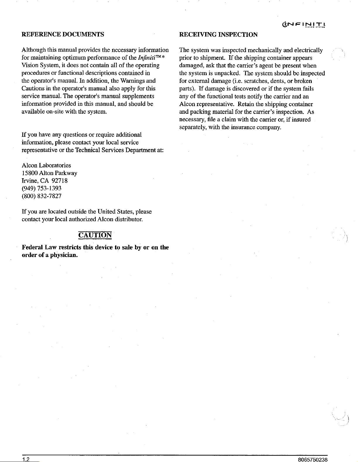
Although
for
Vision
procedures
the
Cautions
service
information
available
If
you
information,
representative
Alcon
15800
Irvine,
(949)
(800)
If
you
contact
this
manual
maintaining
System,
or
functional
operator's
in
the
manual.
manual.
provided
on-site
have
any
please
or
Laboratories
Alton
Parkway
CA
92718
753-1393
832-7827
are
located
your
local
provides
optimum
it
does
performance
not
descriptions
In
addition,
operator's
The
with
questions
manual
operator's
in
this
the
system.
or
contact
the
Technical
outside
the
authorized
the
contain
manual
manual,
require
your
local
Services
United
Alcon
necessary
of the
ail
of
the
operating
contained
the
Warnings
also
apply
supplements
and
should
additional
service
Department
States,
please
distributor.
information
Infiniti™*
in
and
for
this
be
at:
The
system
prior
to
shipment.
damaged,
the
for
parts).
any
Alcon
and
necessary,
separately,
ask
system
external
of
is
If
damage
the
functional
representative.
packing
file a claim
with
was
inspected
If
that the
unpacked.
damage
is
material
the
insurance
mechanically
the
shipping
carrier’s
(i.e.
agent
The
system
scratches,
discovered
tests
notify
Retain
for the
with
the
carrier’s
the
carrier
company.
container
be
should
dents,
or
if
the
the
carrier
shipping
inspection.
or,
and
electrically
appears
present
system
be
or
and
broken
when
inspected
fails
an
container
if
insured
As
Federal
order
Law
of a physician.
CAUTION
restricts
this
device
to
sale
by
or
on
the
Page 11
ONFINITI
UNPACKING
1.
2.
3.
4.
5.
6.
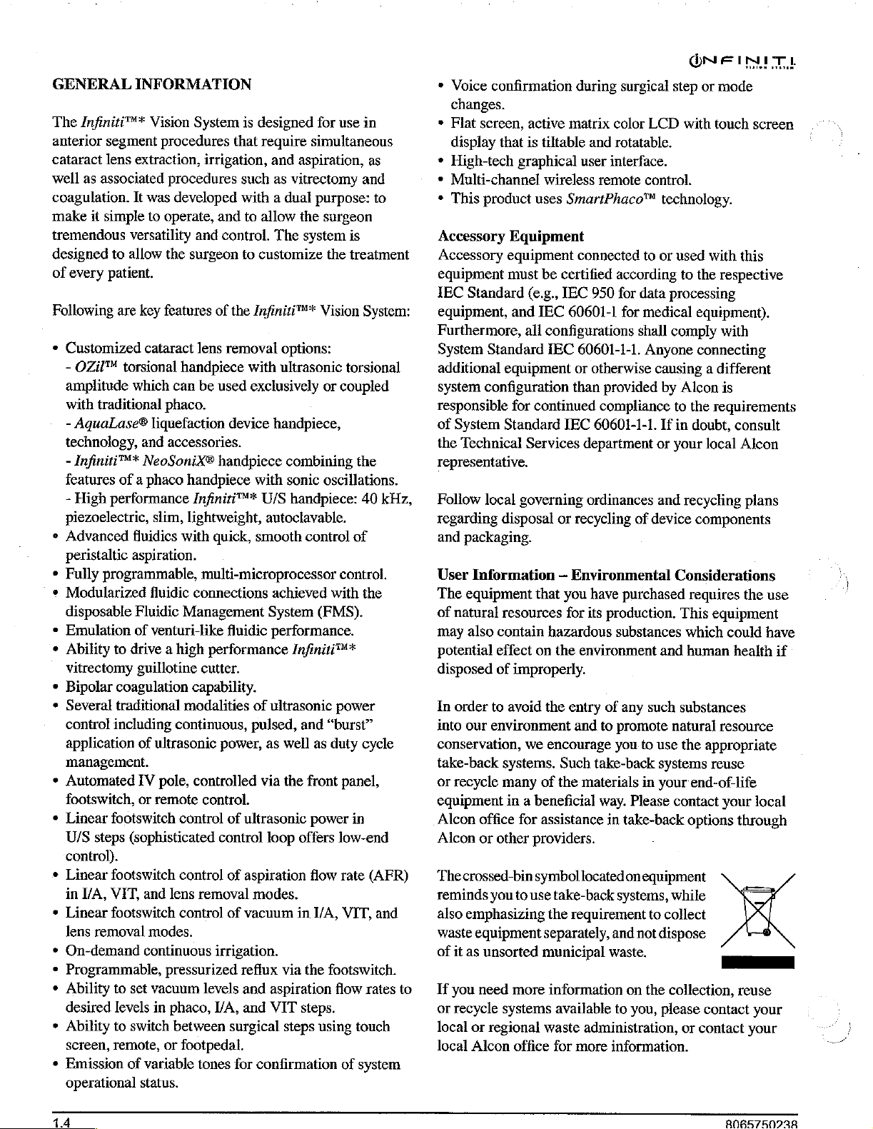
With
the
carton
pallet,
lid
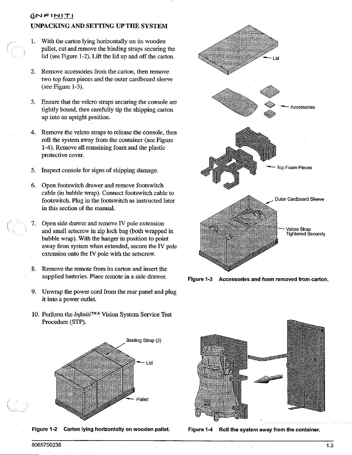
Remove
two
(see
Ensure
tightly
up
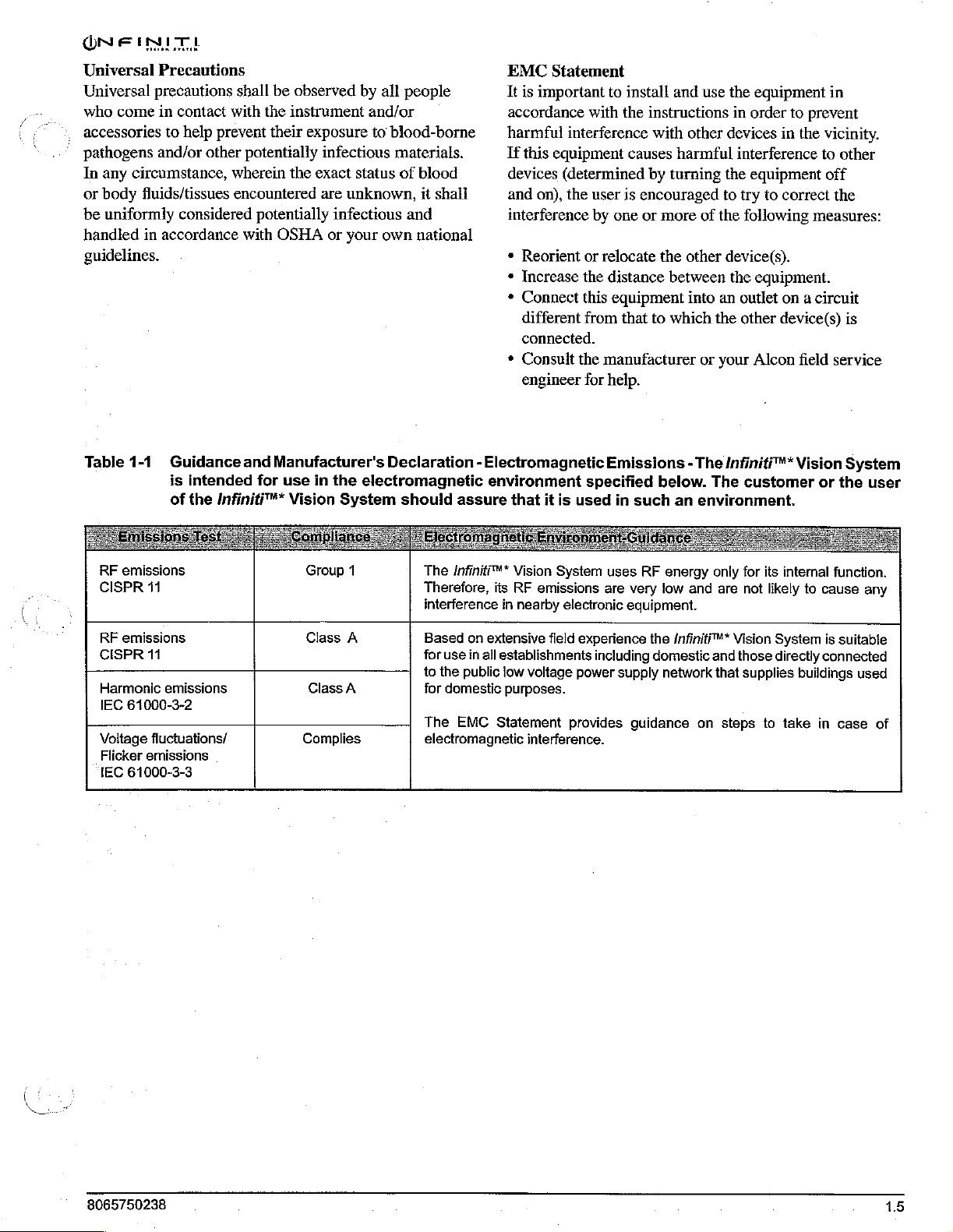
Remove
roll
protective
‘Inspect
Open
cable
footswitch.
(see
top
Figure
into
the
1-4).
in
this
cut
and
Figure
accessories
foam
that the
bound,
an
upright
the
system
Remove
cover.
console
footswitch
(in
bubble
section
AND
remove
1-2).
pieces
1-3).
velcro
then
velcro
away
all
Plug
of
SETTING
lying
horizontally
the
Lift the
from
and
straps
carefully
position.
straps
from
remaining
for
signs
drawer
wrap).
in
the
the
manual.
Connect
footswitch
UP
binding
lid
up
the
carton,
the
outer
securing
tip
to
release
the
container
foam
of
shipping
and
remove
THE
SYSTEM
on
its
wooden
straps
securing
and
off the
then
remove
cardboard
the
console
the
shipping
the
console,
(see
and
the
plastic
damage.
footswitch
footswitch
as
instructed
carton.
sleeve
carton
then
Figure
cable
later
the
are
to
x
gi
>
<
—
~~
per
E,
Top
Outer
-
Accessories
Foam
Pieces
Cardboard
Sleeve
Č
`
7.
i
8.
9.
10.
Open
side
drawer
and
small
setscrew
bubble
away
extension
Remove
supplied
Unwrap
it
Perform
Procedure
wrap).
from
onto
the
batteries.
the
into a power
the
(STP).
and
in
With
the
system
when
the
TV
remote
power
Infiniti™*
from
Place
cord
outlet.
remove
zip
lock
hanger
extended,
pole
with
its
remote
from
Vision
IV
pole
bag
(both
in
position
the
carton
in
the
rear
System
Binding
extension
wrapped
to
secure
a
the
setscrew.
and
insert
side
drawer.
panel
Service
Strap
point
IV
the
and
plug
Test
(2)
in
pole
Figure
1-3.
Accessories
and
foam
Velcro
Tightened
removed
Strap
Securely
from
carton.
Figure
8065750238.
1-2
Carton
lying
horizontally
—™—
on
Pallet
wooden
pallet.
Figure
1-4
Roll
the
system
away
from
the
container.
13
Page 12
ONFINI
GENERAL
The
Injiniti™*
anterior
cataract
well
coagulation.
make
tremendous
designed
of
Following
*
segment
lens
as
associated
it
simple
versatility
to
allow
every
patient.
are
Customized
-
OZil™
torsional
amplitude
with
traditional
-
AquaLase®
It
which
technology,
-
Infiniti™*
features
-
High
of a phaco
performance
piezoelectric,
+
Advanced
peristaltic
+
Fully
+
Modularized
fluidics
aspiration.
programmable,
disposable
*
Emulation
»
Ability
of
to
drive a high
vitrectomy
¢
Bipolar
¢
Several
control
coagulation
traditional
including
application
management.
*
Automated
footswitch,
*
Linear
U/S
control).
¢
Linear
in
¢
Linear
lens
*
On-demand
¢
Programmable,
*
Ability
desired
*
Ability
screen,
*
Emission
Operational
footswitch
steps
footswitch
I/A,
VIT,
footswitch
removal
to
levels
to
remote,
(sophisticated
set
switch
of
INFORMATION
Vision
extraction,
was
to
key
cataract
and
NeoSoniX®
fluidic
Fluidic
venturi-like
guillotine
of
IV
or
and
modes.
continuous
vacuum
variable
status.
System
procedures
irrigation,
procedures
developed
operate,
and
and
the
surgeon
features
of
lens
handpiece
can
be
used
phaco.
liquefaction
accessories.
handpiece
Infiniti™*
slim,
lightweight,
with
quick,
multi-microprocessor
connections
Management
performance
cutter.
capability.
modalities
continuous,
ultrasonic
pole,
controlled
remote
control.
control
control
lens
removal
control
irrigation.
pressurized
levels
in
phaco,
I/A,
between
or
footpedal.
tones
is
designed
that
require
and
such
as
with a dual
to
allow
control.
the
The
to
customize
Infiniti™*
removal
with
exclusively
device
handpiece,
handpiece
with
U/S
autoclavable.
smooth
achieved
System
fluidic
performance.
of
ultrasonic
pulsed,
power,
as
via the
of
ultrasonic
control
loop
of
aspiration
modes.
of
vacuum
reflux
and
aspiration
and
VIT
surgical
for
confirmation
for
use
simultaneous
aspiration,
vitrectomy
purpose:
the
surgeon
system
the
Vision
options:
ultrasonic
torsional
or
coupled
combining
sonic
oscillations.
handpiece:
control
control.
with
(FMS).
Infiniti™*
power
and
“burst”
well
as
duty
front
panel,
power
offers
low-end
flow
rate
in
I/A,
VIT,
via the
footswitch.
flow
steps.
steps
using
of
in
as
and
to
is
treatment
System:
the
40
kHz,
of
the
cycle
in
(AFR)
and
rates
to
touch
system
»
Voice
confirmation
during
changes.
»
Fiat
screen,
display
+
High-tech
+
Multi-channel
*
This
product
Accessory
Accessory
equipment
IEC
Standard
equipment,
Furthermore,
System
additional
system
configuration
responsible
of
System
the
Technical
active
that
is
graphical
uses
Equipment
equipment
must
(e.g.,
and
IEC
ali
Standard
equipment
for
continued
Standard
Services
matrix
tiltable
user
wireless
SmartPhaco™
connected
be
certified
IEC
60601-1
configurations
TEC
60601-1-1.
or
than
TEC
department
representative.
Follow
regarding
and
User
The
of
may
potential
disposed
In
into
conservation,
take-back
or
equipment
Alcon
Alcon
Thecrossed-bin
reminds
also
waste
of
local
governing
disposal
ordinances
or
recycling
packaging.
Information — Environmental
equipment
natural
also
order
to
our
environment
recycle
that
resources
contain
effect
of
hazardous
on
improperly.
avoid
the
we
encourage
systems.
many
of
you
for
its
the
environment
entry
and
Such
the
materials
in a beneficial
office
for
assistance
or
other
providers.
you
to
emphasizing
equipment
it
as
unsorted
symbol
use
located
take-back
the
requirement
separately,
municipal
P
If
you
need
more
information
or
recycle
local
local
systems
or
regional
Alcon
waste
office
available
administration,
for
more
surgical
color
LCD
and
rotatable.
interface.
remote
control.
to
according
950
for
data
for
medical
shall
Anyone
otherwise
provided
compliance
60601-1-1.
of
have
purchased
production.
substances
of
any
such
to
promote
you
to
take-back
in
way.
Please
in
take-back
on
equipment
systems,
to
and
not
waste.
on
the
to
you,
information.
step
or
mode
with
touch
screen
technology.
or
used
with
this
to
the
respective
processing
equipment).
comply
with
connecting
causing a different
by
Alcon
is
to
the
requirements
If
in
doubt,
consult
or
your
local
Alcon
and
recycling
device
components
plans
Considerations
This
and
requires
which
human
the
use
equipment
could
have
health
substances
natural
use
systems
your
contact
resource
the
appropriate
reuse
end-of-life
your
options
through
local
while
collect
dispose
m-
collection,
please
or
reuse
contact
contact
your
your
if
Page 13
ONE
Universal
Universal
who
IMT!
Precautions
precautions
come
in
accessories
pathogens
In
any
or
body
be
uniformly
handled
and/or
circumstance,
fluids/tissues
in
accordance
guidelines.
Table
1-1
contact
to
help
prevent
other
considered
Guidance
is
intended
of
the
Infiniti™*
shall
be
observed
with
the
instrument
their
potentially
wherein
encountered
the
potentially
with
OSHA
and
Manufacturer's
for
use
Vision
by
and/or
exposure
to’
infectious
exact
status
are
unknown,
infectious and
or
your
in
the
electromagnetic
System
EMC
Statement
all
people
It is
important
accordance
blood-borne
materials.
of
blood
it
shall
harmful
If
this
equipment
devices
and
on),
interference
(determined
the
interference
own
national
*
Reorient
*
Increase
+
Connect
different
the
this
connected.
*
Consult
the
engineer
Declaration - Electromagnetic
environment
should
assure
that
it
is
used
to
instal!
with
the
instructions
with
causes
by
user
is
encouraged
by
one
or
more
or
relocate
the
distance
equipment
from
that
to
manufacturer
for
help.
Emissions - The
specified
in
below.
such
and
use
other
harmful
turning
of
other
between
into
which
the
or
your
The
an
environment.
the
equipment
in
order
to
devices
in
interference
the
equipment
to
try
to
correct
the
following
device(s).
the
equipment.
an
outlet
on a circuit
other
device(s)
Alcon
Infiniti™*
customer
in
prevent
the
vicinity.
to
other
off
the
measures:
field
service
Vision
or
the
is
System
user
RF
emissions
CISPR
RF
emissions
CISPR
Harmonic
IEC
61000-3-2
Voltage
Flicker
EC
61000-3-3
11
11
emissions
fluctuations/
emissions
Group
1
Class
A
Class
A
Complies
The
Infiniti™*
Therefore,
interference
Based
for
use
to
the
for
domestic
The
electromagnetic
its
in
on
extensive
in
all
establishments
public
low
purposes.
EMC
Statement
Vision
System
RF
emissions
nearby
electronic
field
experience
voltage
interference.
power
provides
uses
RF
are
very
eguipment.
the
including
supply
guidance
energy
low
and
Infiniti™*
domestic
network
on
only
are
Vision
and
that
steps
for
its
internal
not
likely
System
those
directly
supplies
to
take
function.
to
cause
is
suitable
connected
buildings
in
case
any
used
of
8065750238
15
Page 14
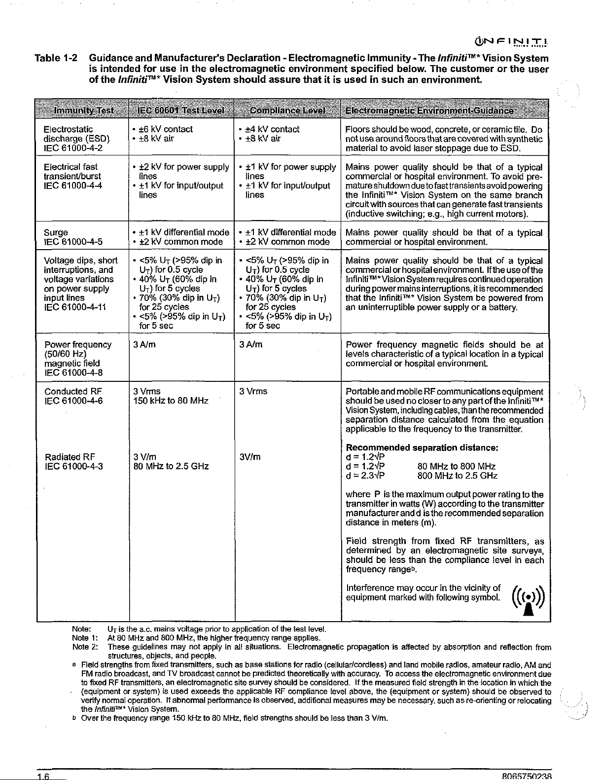
Table
1-2
Electrostatic
discharge
IEC
Electrical
transient/burst
IEC
Surge
IEC
Voltage
interruptions,
voltage
on
input
IEC
Power
(50/60
magnetic
IEC
Conducted
IEC
(ESD)
61000-4-2
fast
61000-4-4
61000-4-5
dips,
variations
power
supply
lines
61000-4-11
frequency
Hz)
field
61000-4-8
61000-4-6
Guidance
is
intended
of
the
Infiniti™*
short
and
RF
and
Manufacturer's
for
use
Vision
*
+6
KV
*
*
*
+
*
*
+
»
*
3A/m
3
150
contact
+8
kV
air
+2
kV
for
lines
#1
kV
for
lines
+1
kV
differential
+2
KV
common
<5%
Ur
Ur)
for
0.5
40%
Ur
Ur)
for 5 cycles
70%
(30%
for
25
cycles
<5%
(>95%
for 5 sec
Vins
kHz
to
(>95%
(60%
Declaration - Electromagnetic
in
the
electromagnetic
System
power
input/output | +
mode
dip
cycle
dip
dip
in
dip
in
80
MHz
should
ㆍ
・
supply | +
mode | +
{| + +2 KV
in
in
Uy)
Uy)
*
*
*
3A/m
3
assure
+4
KV
contact
は 8
kV
ar
+1
kV
for
lines
+7
kV
for
lines
+1
kV
differential
common
<5%
Ur
Ur)
for
0.5
40%
Ur
Ur)
for 5 cycles
70%
(30%
for
25
cycles
<5%
(>95%
for 5 sec
Vrms
environment
that
power
supply | Mains
input/output | mature
mode | Mains
mode | commercial
(>95%
dip
cycle
(60%
dip
in
dip
in
Ur)
dip
in
Ur)
it
in
is
specified
used
Floors
not
use
material
commercial
the
circuit
(inductive
Mains
commercial
Infiniti™*
during
that
an
uninterruptible
Power
levels
commercial
Portable
should
Vision
separation
applicable
Immunity - The
below.
in
such
an
should
be
around
to
power
shutdown
Infiniti™*
with
power
power
power
the
Infiniti™*
freguency
characteristic
and
be
System,
wood,
floors
avoid
laser
quality
or
hospital
due
Vision
sources
switching;
quality
or
hospital
quality
or
hospital
Vision
System
mains
Vision
or
hospital
mobile
used
no
closer
including
distance
to
the
frequency
power
Q@NF
Infiniti™*
The
customer
environment.
concrete,
that
stoppage
should
environment.
to
fast
System
that
can
e.g.,
should
environment.
should
environment.
requires
interruptions,
magnetic
of a typical
environment.
RF
communications
to any
cables,
calculated
or
are
covered
due
be
transients
on
the
generate
high
current
be
be
continued
System
supply
itis
be
or a battery.
fields
location
part
than
from
to
the
INIT)
Vision
ceramictile.
that
that
that
the
transmitter.
System
or
the
with
synthetic
to
ESD.
of a typical
To
avoid
avoid
powering
same
branch
fast
transients
motors).
of a typical
of a typical
Ifthe
use
of
operation
recommended
powered
should
of
recommended
be
in a typical
eguipment
the
infiniti™*
the
equation
user
Do
pre-
the
from
at
Radiated
IEC
RF
61000-4-3
Note:
Note
1:
Note
2:
a
Field
FM
radio
to
fixed
{equipment
verify
the
Infiniti™*
b
Over
3
Vim
80
MHz
Uris
the
a.c,
At
80
These
structures,
strengths
broadcast,
RF
transmitters,
or
normal
the
frequency
mains
MHz
and
guidelines
objects,
from
fixed
and
system)
operation.
Vision
System.
range
to
2.5
GHz
voltage
800
MHz,
the
may
not
and
people.
transmitters,
TV
broadcast
an
electromagnetic
is
used
exceeds
!f
abnormal
150
kHz
3V/m
prior
to
application
higher
apply
to
frequency
in
all
such
as
cannot
site
the
applicable
performance
80
MHz,
be
of
the
range
situations.
base
stations
predicted
survey
should
RF
is
observed,
field
strengths
test
Electromagnetic
for
theoretically
compliance
level.
applies.
radio
(cellular/cordless)
be
considered.
additional
should
be
Recommended
d=
1.2YP
d=
1.2YP
d=2.3YP
where P is
transmitter
manufacturer
distance
Field
determined
should
frequency
Interference
equipment
in
strength
be
separation
the
maximum
in
watts
and d is
meters
from
by an
less
than
rangeb.
may
marked
80
MHz
800
MHz
(W)
according
the
(m).
fixed
electromagnetic
the
occur
in
with
following
propagation
with
accuracy.
level
above,
measures
less
than 3 V/m.
If
the
and
To
measured
the
(equipment
may
be
is
affected
land
mobile
access
field
necessary,
by
the
electromagnetic
strength
or
such
distance:
to
800
MHz
to
2.5
GHz
output
power
RF
the
vicinity
symbol.
amateur
in
the
should
as
re-orienting
to
transmitters,
and
location
recommended
compliance
absorption
radios,
system)
rating
the
transmitter
separation
site
surveya,
level
in
of
(인
reflection
radio,
environment
in
which
be
observed
or
relocating
to
the
as
each
from
AM
and
due
the
to
ン
ミュ
Page 15
ONFINITI
Table
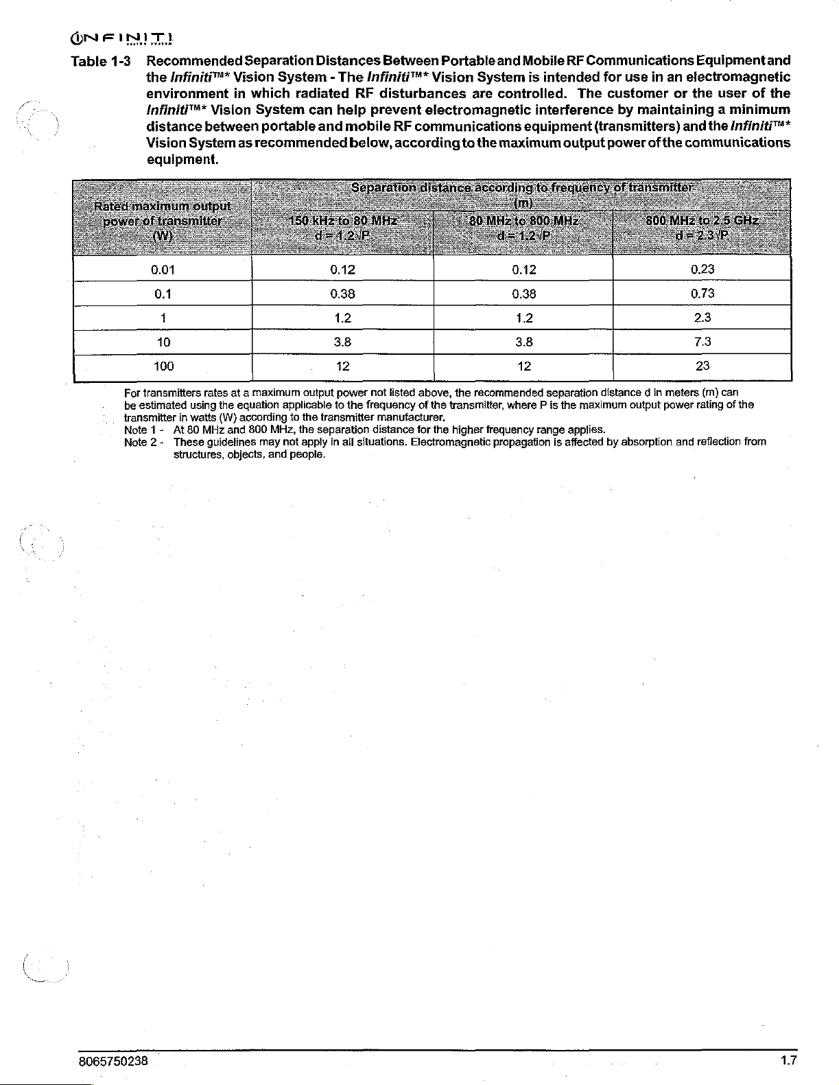
1-3
Recommended
the
Infiniti™*
environment
infiniti™*
distance
Vision
equipment.
10
100
For
transmitters
be
estimated
transmitter
Note
1-
Note
At
2-
These
structures,
between
System
rates
using
in
watts
80
MHz
Separation
Vision
in
which
Vision
System
as
recommended
at a maximum
the
equation
(W)
according
and
guidelines
800
objects,
System - The
radiated
can
portable
output
applicable
to
the
MHz,
the
may
not
apply
and
people.
Distances
help
and
3.8 3.8
12 12
Between
Infiniti™*
RF
disturbances
prevent
mobile
below,
Portable
Vision
electromagnetic
RF
communications
according
to
are
the
System
power
not
listed
above,
the
to
the
in
all
situations.
frequency
transmitter
separation
of
manufacturer.
distance
the
for
Electromagnetic
recommended
transmitter,
the
higher
frequency
and
Mobile
is
intended
controlled.
interference
equipment
maximum
separafion
where P is
propagation
range
is
RF
Communications
for
The
customer
(transmitters)
output
power
distance d in
the
maximum
applies.
affected
by
Equipment
use
in
an
electromagnetic
or
the
user
by
maintaining a minimum
and
the
of
the
communications
7.3
23
meters
(m)
output
power
absorption
and
can
rating
reflection
and
of
the
Infiniti™*
of
the
from
8065750238
17
Page 16

WARNINGS
Most
of
these
manual;
greater
please
the
however,
detail
contact
Technical
The
Infiniti"
be
serviced
engineer.
lead
to
Good
clinical
irrigation,
applicable
eye.
Ensure
any
phase
AND
CAUTIONS
warnings
here.
your
Services
by a factory-trained
Access
injury.
practice
aspiration
for
that
the
of
operation.
are
for
easy
If
additional
local
Department.
Vision
by
flow,
each
handpiece
tubings
Alcon
dictates
stated
elsewhere
reference
information
service
System
untrained
testing
reflux,
are
not
in
this
they
are
repeated
is
required,
representative,
battery
and
prior
occluded
can
Alcon
personnel
service
for
adequate
operation
to
entering
during
There
or
Infiniti™*
all
engineer.
in
WARNINGS!
only
can
as
:
are
no
service
Do
not
use
IV
pole.
Keep
clear
prevent
trapped
moves
height
Keep
from
clothing
during
adjustment.
clear
stored
user
Vision
issues
Legacy®
of
skin,
in
the
of
position
from
serviceable
System
to
the
hair,
power
display
being
console
your
factory-trained
pole
IV
pole
and/or
IV
pole
mechanism.
on/off,
base
to
prevent
trapped
components
or
footswitch.
extender
when
clothing
when
with
it
is
priming,
raising
skin,
at
the
base.
inside
Alcon
Infiniti™*
in
motion
from
The
and
hair,
the
Refer
service
to
being
IV
pole
bottle
display
and
/or
Do
notexceed
ml).
Excessive
drain
bag
in a hazardous
Inadvertent
handpiece
condition
Inadvertent
system
If
the
handpiece
tuning, there
through
imbalance.
or
collapsing
If
the
Infiniti™*
-
240V
range
should
phase
be
circuit.
maximum
maximum
actuation
is in
that
pressing
is
active
is a potential
the
handpiece
This,
of
in
used
pressure
capacity
condition
the
eye
may
result
will
cause
test
chamber
in
turn,
the
anterior
Vision
System
the
United
on a center-tapped,
capacity
can
resultfrom
and
for
the
of
Prime
can
in
patient
of
Standby
unit
of
and
may
may
chamber.
States
of
drain
bag
(500
exceeding
potentially
patient.
or
Tune
create a hazardous
injury.
switch
to
shut
is
collapsed
low
irrigation
result
cause a shallowing
is
used
or
result
while
when
down.
after
flow
in a fluidic
at
the
220V
Canada,
240V
single
a
it
A
gualified
inspection
twelve
+
*
*
In
Alcon
A
continuity
to
(for
be
standards,
do
Services.
Use
provided
decreased
mobile
this
months:
Warning
Power
Fuses
case
ensure
Cord
of a deficiency,
Technical
qualified
they
example:
recorded,
not
use
of
accessories
RF
medical
technician
of
the
Labels
Services.
technician
for
leakage
are
within
EN60601-1/1EC601-1).
and
if
or
50%
the
system;
may
result
immunity
communications
electrical
must
following
do
current
the
they
are
above
and
cables
in
increased
of
the
equipment.
perform
components
not
use
must
every
applicable
above
initial
call
Alcon
system.
equipment
the
system;
check
twelve
standards
Values
the
applicable
measurement,
Technical
other
than
emissions
Portable
can
a
visual
every
:
ground
months
must
those
and
affect
call
or
1.8
Page 17
ÓN
EIDE
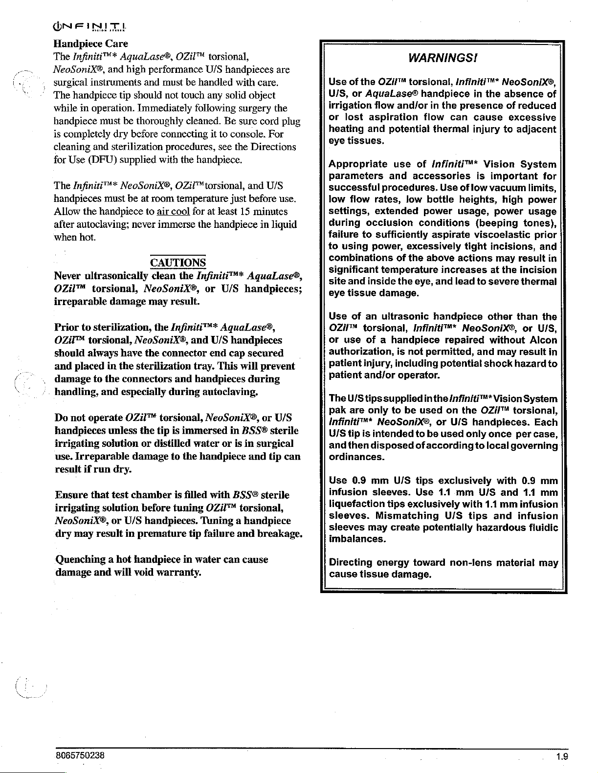
Handpiece
The
Infiniti™*
NeoSoniX®,
.
surgical
The
handpiece
while
in
handpiece
is
completely
cleaning
for
Use
The
Infiniti™*
handpieces
Allow
the
after
autoclaving;
when
hot.
Never
OZil™
irreparable
Prior
OZil™
should
and
damage
handling,
Do
handpieces
irrigating
use.
result
Ensure
irrigating
NeoSoniX®,
dry
ultrasonically
to
placed
not
Irreparable
if
may
Care
AquaLase®,
and
high
instruments
operation.
must
dry
and
sterilization
(DFU)
must
handpiece
torsional,
damage
sterilization,
torsional,
always
in
to
the
and
operate
unless
solution
run
dry.
that
test
solution
or
result
and
tip
should
Immediately
be
thoroughly
before
supplied
NeoSoniX®,
be
at
to
never
NeoSoniX®,
NeoSoniX®,
have
the
the
sterilization
connectors
especially
OZil™
the
or
damage
chamber
before
U/S
handpieces.
in
premature
OZil™
performance
must
be
handled
not
touch
following
cleaned.
connecting
procedures,
with
the
handpiece.
OZil™
room
temperature
air
cool
immerse
CAUTIONS
clean
may
the
connector
torsional,
tip
distilled
for
the
the
Infiniti™*
result.
Infiniti™*
and
tray.
and
handpieces
during
is
immersed
water
to
the
is
filled
tuning
tip
torsional,
U/S
handpieces
with
any
solid
surgery
Be
sure
it
to
console.
see
the
torsional, and
just
at
Jeast
15
handpiece
AquaLase®,
or
U/S
handpieces;
AquaLase®,
U/S
handpieces
end
cap
This
will
autoclaving.
NeoSoniX®,
in
BSS®
or
is
in
handpiece
with
BSS®
OZil™
Tuning a handpiece
failure
torsional,
and
are
care.
object
the
cord plug
For
Directions
U/S
before
secured
during
and
use.
minutes
in
liquid
prevent
or
U/S
sterile
surgical
tip
sterile
breakage.
can
Use
of
the
U/S,
or
AquaLase®
irrigation
or
lost
aspiration
heating
eye
Appropriate
Parameters
successful
low
settings,
during
failure
to
combinations
significant
site
eye
Use
OZiMm
or
authorization,
patient
patient
The
pak
Infiniti
U/S
andthen
ordinances.
Use
infusion
liquefaction
sleeves.
sleeves
imbalances.
and
tissues.
flow
occlusion
to
using
power,
and
inside
tissue
of
an
torsional,
use
of a handpiece
injury,
and/or
U/Stips
are
only
"*
tip
is
intended
disposed
0.9
mm
sleeves.
may
WARNINGS!
OZi/™
flow
rates,
extended
sufficiently
damage.
NeoSoniX®,
Mismatching
torsional,
handpiece
and/or
potential
use
of
and
accessories
procedures.
low
conditions
excessively
of
the
temperature
the
eye,
ultrasonic
Infiniti™*
is
not
including
operator.
supplied
to
be
used
to
ofaccording
U/S
tips
Use
tips
exclusively
create
potentially
Infiniti™*
in
the
presence
flow
can
thermal
Infiniti™*
Use
of
bottle
power
above
permitted,
inthe
be
heights,
usage,
aspirate
tight
actions
increases
and
lead
handpiece
NeoSoniX®,
repaired
potential
/nfiniti™*
on
the
or
U/S
used
only
exclusively
1.1
mm
with
U/S
NeoSonix®,
in
the
absence
of
cause
injury
is
low
(beeping
viscoelastic
to
and
handpieces.
to
U/S
tips
hazardous
excessive
to
Vision
important
vacuum
high
power
incisions,
may
at
the
severe
other
without
may
shock
Vision
OZi/™
once
local
governing
with
and
1.1
mm
and
of
reduced
adjacent
System
for
limits,
power
usage
tones),
prior
and
result
than
result
hazard
torsional,
per
infusion
in
incision
thermal
the
or
UIS,
Alcon
in
to
System
Each
case,
0.9
mm
11
mm
infusion
fluidic
Quenching a hot
damage
8065750238
and
will
handpiece
void
warranty.
in
water
can
cause
Directing
cause
energy
tissue
toward
damage.
non-lens
material
may
1.9
Page 18
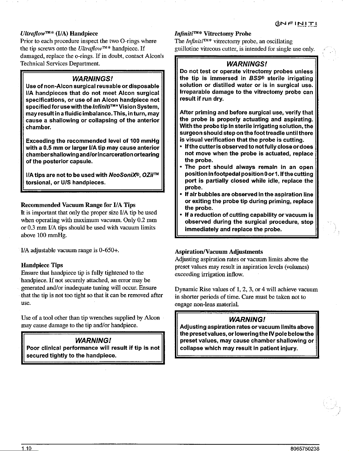
Uliraflow™*
Prior
to
the
tip
screws
damaged,
Technical
Use
of
VA
handpieces
specifications,
specified
may
resultin a fluidic
cause a shallowing
chamber.
Exceeding
with a 0.5
chamber
of
the
VA
tips
torsional,
Recommended
It
is
important
when
operating
or
0.3
mm
above
100
(U/A)
each
procedure
onto
replace
Services
non-Alcon
for
use
the
mm
shallowing
posterior
are not
or
U/S
Vacuum
that
with
WA
tips
mmHg.
Handpiece
inspect
the
Ultraflow™*
the
o-rings.
Department.
WARNINGS!
surgical
that
do
or
use
with
the
imbalance.
or
recommended
or
larger
and/orincarceration
capsule.
to
be
used
handpieces.
only
the
maximum
should
the
If
in
reusable
not
of
an
Infiniti™*
collapsing
I/A tip
with
Range
proper
vacuum.
be
used
two
handpiece.
doubt,
meet
Alcon
Alcon
Vision
This,
level
may
NeoSonix®,
for
VA
size
with
O-rings
contact
or
disposable
surgical
handpiece
System,
inturn,
of
the
anterior
of
100
cause
I/A
vacuum
anterior
ortearing
Tips
tip
be
Only
0.2
where
If
Alcon's
not
may
mmHg
OZiI™
used
mm
limits
Infiniti™*
The
guillotine
Do
the
solution
Irreparable
result
After
the
With
surgeon
is
*
*
*
*
Vitrectomy
Infiniti™*
vitreous
not
test
tip
is
immersed
or
if
run
priming
probe
visual
Ifthe
not
the
The
position
port
probe.
If
air
or
exiting
the
Ifa
observed
immediately
is
the
probe
should
verification
cutteris
move
probe.
port
in
is
partially
bubbles
probe.
reduction
Probe
vitrectomy
cutter,
WARNINGS!
or
operate
distilled
damage
dry.
and
properly
when
should
footpedal
the
during
to
before
tip
in
sterile
step
on
that
observed
the
always
closed
are
observed
probe
of
cutting
the
and
replace
probe,
is
in
water
probe
position 0 or
tip
an
intended
vitrectomy
BSS®
or
is
the
vitrectomy
surgical
actuating
irrigating
the
foot
the
probe
to
not
is
remain
while
in
during
capability
surgical
the
oscillating
for
single
use
probes
sterile
in
surgical
use,
and
treadle
is
fully
close
actuated,
1.
idle,
the
aspiration
priming, replace
procedure,
probe.
unless
irrigating
probe
verify
aspirating.
solution,
until
there
cutting.
ordoes
replace
in
an
open
Ifthe
cutting
replace
or
vacuum
only.
use.
can
that
the
the
line
is
stop
V/A
adjustable
Handpiece
Ensure
handpiece.
generated
that
use.
Use
may
the
of a tool
cause
Poor
secured
that
and/or
tip
clinical
vacuum
Tips
handpiece
If
not
securely
inadequate
is
not too
other
than
damage
tightly
to
performance
to
range
is
tip
is
fully
attached,
tuning
tight
so
that
tip
wrenches
the
tip
and/or
WARNING!
the
handpiece.
0-650+.
tightened
an
will
it
can
supplied
handpiece.
will
resuit
to
error
occur.
be
removed
if
the
may
Ensure
by
tip
be
after
Alcon
is
not
Aspiration/Vacuum
Adjusting
preset
values
exceeding
Dynamic
in
shorter
engage
non-lens
Adjusting
the
preset
preset
collapse
aspiration
may
result
irrigation
Rise
values
periods
values,
of
material.
aspiration
values,
may
which
may
Adjustments
rates
or
vacuum
in
aspiration
inflow.
of
1,2,
3,
time.
Care must
WARNING!
rates
or
or
lowering
cause
result
chamber
in
limits
levels
or 4 will
be
vacuum
the
IV
pole
patient
above
(volumes)
achieve
taken
shallowing
injury.
not
limits
belowthe
vacuum
above
the
to
or
Page 19
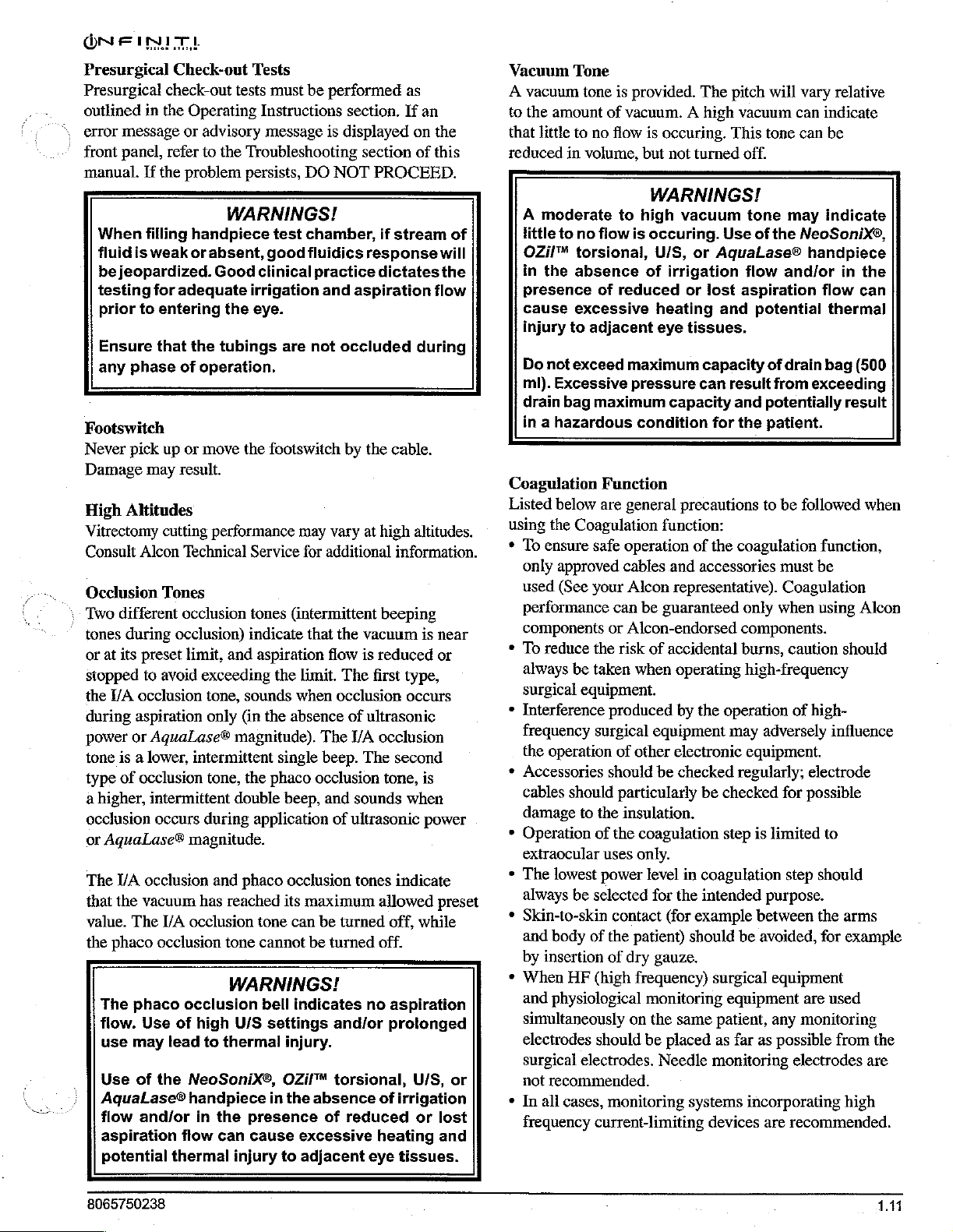
Presurgical
Presurgical
outlined
error
message
front
panel,
manual.
When
fluid
is
be
jeopardized.
testing
prior
Ensure
any
phase
Footswitch
Never
pick
Damage
High
Altitudes
Vitrectomy
Consult
Occlusion
\
Two
different
tones
during
or
at its
stopped
the
I/A
during
power
tone
type
a
occlusion
or
The
that
value.
the
8065750238
aspiration
or
is a lower,
of
higher,
AquaLase®
I/A
the
The
phaco
The
phaco
flow.
use
may
Use
AquaLase®
flow
aspiration
potential
Check-out
check-out
in
the
Operating
or
advisory
refer
to
If
the
problem
filling
to
Alcon
preset
to
occlusion
occlusion
occlusion
vacuum
Use
of
and/or
handpiece
weak
or
absent,
for
adequate
entering
that
the
of
operation.
up
or
move
may
result.
cutting
Technical
Tones
occlusion
occlusion)
limit,
avoid
exceeding
tone,
only
AquaLase®
intermittent
tone,
intermittent
occurs
during
magnitude.
has
I/A
occlusion
occlusion
occlusion
of
high
lead
to
the
NeoSonixX®,
handpiece
in
flow
thermal
Tests
tests
must
Instructions
message
the
Troubleshooting
persists,
WARNINGS!
test
good
Good
clinical
irrigation
the
eye.
tubings
performance
and
magnitude). The
double
and
reached
tone
WARNINGS!
U/S
thermal
the
can
injury
are not
the
footswitch
Service
tones
(intermittent
indicate
aspiration
the
sounds
(in
the
phaco
presence
when
the
absence
single
phaco
beep,
application
occlusion
its
tone
can
cannot
bell
indicates
settings
injury.
OZil™
in
the
cause
to
be
performed
section.
is
displayed
DO
NOT
chamber,
fluidics
practice
and
aspiration
occluded
by
may
vary
for
additional
that
the
flow
limit.
The
occlusion
of
YA
beep.
occlusion
and
sounds
of
ultrasonic
tones
maximum
be
turned
be
turned
and/or
torsional,
absence
of
reduced
excessive
adjacent
as
If
an
on
section
response
the
at
vacuum
is
ultrasonic
The
no
eye
of
PROCEED.
if
stream
dictates
during
cable.
high
altitudes.
information.
beeping
is
reduced
first
type,
occurs
occlusion
second
tone,
is
when
power
indicate
allowed
off,
while
off.
aspiration
prolonged
U/S,
of
irrigation
or
heating
tissues.
the
this
of
will
the
flow
near
or
preset
or
lost
and
Vacuum
A
to
that
reduced
Coagulation
Listed
using
*
+
*
*
*
*
*
+
*
Tone
vacuum
the
A
little
OZ が torsional,
in
presence
cause
injury
Do
ml).
drain
in a hazardous
To
only
used
performance
components
To
always
surgical
Interference
frequency
the
Accessories
cables
damage
Operation
extraocular
The
always
Skin-to-skin
and
by
When
and
simultaneously
electrodes
surgical
not
In
frequency
tone
is
amount
little
moderate
to
the
not
Excessive
below
the
ensure
approved
(See
reduce
operation
lowest
body
insertion
physiological
recommended.
all
of
to
no
flow
in
volume,
to
no
flow
absence
of
reduced
excessive
to
adjacent
exceed
bag
maximum
Function
are
Coagulation
safe
cables
your
can
or
the
risk
be
taken
equipment.
produced
surgical
of
should
should
HF
cases,
particularly
to
the
insulation.
of
the
uses
power
be
selected
contact
of
the
of
(high
should
electrodes.
monitoring
current-limiting
provided.
vacuum. A high
is
maximum
pressure
condition
general
operation
Alcon
Alcon-endorsed
when
other
coagulation
only.
patient)
dry
frequency)
on
The
is
occuring.
but not
high
of
be
level
monitoring
be
turned
WARNINGS!
vacuum
occuring.
U/S,
irrigation
heating
eye
capacity
function:
and
representative).
guaranteed
of
accidental
operating
by
equipment
electronic
be
for
the
(for
gauze.
the
placed
Needle
Use
or
AquaLase®
or
lost
and
tissues.
capacity
can
for
precautions
of
the
accessories
the
operation
checked
be
checked
step
in
coagulation
intended
example between
should
surgical
equipment
same
patient,
as
monitoring
systems
devices
pitch
will
vary
vacuum
This
off.
tone
flow
aspiration
result
and
the
coagulation
only
components.
burns,
high-frequency
may
equipment.
regularly;
be
far
incorporating
can
tone
can
may
of
the
NeoSonix®,
handpiece
and/or
potential
of
drain
from
exceeding
potentially
patient.
to
be
followed
must
be
Coagulation
when
using
caution
of
high-
adversely
electrode
for
possible
is
limited
step
should
purpose.
the
avoided,
equipment
are
any
monitoring
as
possible
electrodes
are
recommended.
relative
indicate
be
indicate
in
the
flow
can
thermal
bag
(500
result
when
function,
Alcon
should
influence
to
arms
for
example
used
from
the
are
high
1.11
Page 20
+
The
cables
positioned
or
other
*
Temporarily
so
that
*
The
such
avoided
region
are
sucked
e
Non-flammable
disinfection
+
Flammable
or
as
evaporate
materials,
saturated
produced
+
Do
with
devices.
implanted
devices
that
defibrillatory
and
with
manufacturers
*
Failure
circuitry)
of
The
Infiniti™*
the
effects
Cautery,
The
InfinitiTM*
“Coagulation”
following
Coagulation - an
conductors
electrodes,
some
of
to
in
leads
unused
they
are
use
of
flammable
as
nitrous
if a surgical
of the
thorax
away.
wherever
agents
solvents
before
for
with
in
normal
not
use
pacemakers
Ifelectrosurgery
or
irreparable
lead
to
the
pacemaker
ofthe
could
output
power.
of
defibrillator
Diathermy,
in
definition:
(e.g.
halting
the
text
such a way
cardiac
Vision
the
surgical
that
is
avoided.
active
isolated
oxide
agents
of
adhesives,
the
example
oxygen
the
pacemaker
device
ventricular
HF
Vision
place
isolated
forceps).
bleeding.
of
this
from
anaesthetics
(N20)
procedure
or
the
should
possible.
used
for
application
cotton,
may
use
of
WARNINGS!
coagulation
or
pacemakers
damage
and
for
their
surgical
result
CAUTION
System
Coagulation
System
of
Cautery,
bipolar
Current
operator's
electrodes
contact
electrodes
the
and
head,
cleaning
should
be
the
implanted
is
electrodes,
its
fibrillation.
or
recommendations.
equipment
in
an
is
discharge.
uses
(Abbreviated
should
with
should
patient.
or
oxidizing
oxygen
is
unless
be
used
of
wool
ignited
HF
function
used
to
the
function
defibrillatory
unintended
not
the
based
current
passes
manual.)
should
carried
these
for
or
disinfecting,
be
allowed
HF
surgery.
and
gauze,
by
surgical
defibrillatory
on
patients
or
defibrillatory
pacemaker
Please
(coagulation
protected
Definition
word
on
supplied
between
“Coag”
be
the
patient
be
stored
gases
be
out
in
the
agents
cleaning
to
Some
when
sparks
equipment.
on
patients
with
be
aware
may
occur
check
device
increase
against
the
to
these
in
and
or
Consumable
Consumable
System
then
discarded,
All
Infiniti™*
is
important
use.
NOTE:
the
instructions
the
Directions
consumable
Mismatch
of
settings
combination
create a patient
Do
not
date.
Sterile
reused!
These
time
The
equipment
disposables
system.
disposables
create
to
have
equipment
voidance
prevailing
In
all
contained
understood
configurations.
Read
consumable
Paks
items
used
during
use
surgery
unless
paks
to
read
If
an
inconsistency
in
For
pak
or
of
consumable
not
specially
of
hazard.
use
paks
that
disposable
(Accreditation
components
only;
do
used
constitutes a complete
Use
of
may
potential
contributed
under
of
the
hourly
cases,
all
the
in
the
prior
package
paks
with
the
are
designed
labeled
contain
and
the
Use
accessory,
WARNINGS!
consumable
medical
not
disposables
affect
hazards,
contract,
contract
rates.
instrument
manual
label
prior
otherwise.
Directions
understand
exists
operator’s
(DFU)
adjusted
have
exceeded
Manual
have
been
reuse.
in
conjunction
system
and
to
the
to
using
material
to
their
Infiniti™*
to
be
for
the
DFU’s
between
manual
supplied
follow
components
devices
should
the
for a particular
components
for
Hospitals,
designed
other
performance
if
it
malfunction
could
and/or
setup
be
any
printed
use.
used
with
the
should
with
is
result
invoicing
instructions
of
Vision
once
and
Use
(DFU).
prior
to
and
a
DFU.
and use
may
expiration
not
be
1982.)
for
one
the
Alcon
surgical
than
Alcon
and
determined
of
the
in
the
thoroughly
the
pak
on
the
It
at
Page 21
Miscellaneous
*
Donotuse
anesthetics.
*
Avoid
spilling
around
*
Do
IV
are
be
door
*
Do
+
The
located
personnel
Tray
when
the
not
push
pole.
Handles
provided
pulled
thresholds.
not
place
USB
connector
on
support
moving
the
Infiniti™*
BSS®
electrical
or
pull
the
located
for
moving
and
not
pushed,
more
than a 20
(e<»)
the
rear
only.
Failure
WARNING!
must
instrument.
CAUTIONS
Vision
solution,
handpiece
unit
by
at
the
the
instrument.
especially
Ib.
and
panel
are
to
comply
be
set
System
or
moisture
connectors.
the
display,
rear
and
over
load
on
InfinitiM*
for
use
by
will
void
in
its
stored
near
flammable
of
the
tray, or
sides
of
The
unit
elevator
tray
support.
port(
Alcon
warranty.
position
any
kind,
the
should
«d+
trained
the
unit
and
)
[D
8065750238
Page 22
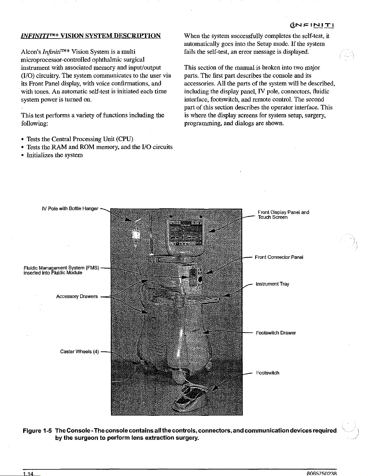
ONFIN
INITITY*
Alcon's
microprocessor-controlled
instrument
C/O)
circuitry.
its
Front
with
tones.
system
power
VISION
Infiniti™*
with
associated
The
Panel
display,
An
automatic
is
turned
SYSTEM
Vision
system
with
on.
System
ophthalmic
memory
communicates
self-test
.
This
test
performs a variety
following:
*
Tests
the
+
Tests
the
*
Initializes
IV
Central
RAM
Pole
the
with
system
Processing
and
ROM
Bottle
Hanger
D
is a multi
and
voice
confirmations,
is
initiated
of
functions
Unit
(CPU)
memory,
and
TI
surgical
input/output
to
the
user
and
each
including
the
I/O
circuits
via
time
the
When
the
system
automatically
fails
the
self-test,
This
section
parts.
accessories.
including
interface,
part
of
is
where
of the
The
first
All
the
display
footswitch,
this
section
the
display
programming,
successfully
goes
into
an
error
manual
part
describes
the
parts
panel,
and
describes
screens
and
dialogs
the
Setup
message
is
of the
IV
remote
for
are
Front
Touch
completes
mode.
is
broken
the
into
console
system
pole,
connectors,
control.
the
operator
system
shown.
|
Display
Screen
the
self-test,
If
the
system
displayed.
two
major
and
its
will
be
described,
The
second
interface.
setup,
surgery,
Panel
and
it
fluidic
This
Fluidic
Management
inserted
Figure
into
1-5
System
Fluidic
Module
Accessory
Caster
The
Console - The
by
the
(FMS)
Drawers
Wheels
surgeon
(4)
to
console
perform
contains
lens
extraction
all
the
controls,
surgery.
connectors,
Front
Instrument
Footswitch
Footswitch
and
communication
Connector
Tray
Drawer
Panel
devices
required
Page 23
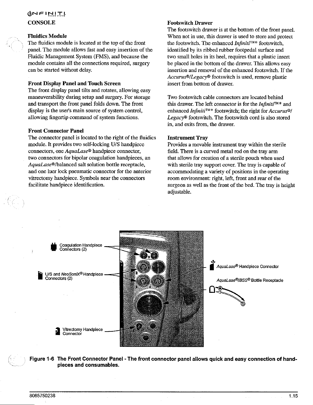
ÓN
FIN
CONSOLE
Fluidics
The
panel.
Fluidic
module
can
Front
The
maneuverability
and
display
allowing
Front
The connector
module.
connectors,
two
AquaLase®/balanced
and
vitrectomy
facilitate
Module
fluidics
The
module
module
Management
contains
be
started
Display
front
display
transport
is
the
the
user's
fingertip
Connector
It
provides
one
connectors
one
luer
lock
handpiece.
handpiece
all
without
Panel
panel
during
front
command
Panel
panel
AquaLase®
for
pneumatic
is
located
allows
fast
at
the
and
System (FMS),
the
connections
delay.
and
Touch
tilts
setup
panel
main
source
is
located
two
self-locking
bipolar
salt
solution
Screen
and
rotates,
and
surgery.
folds
of
of
system
to
the
handpiece
coagulation handpieces,
connector
Symbols
near
identification.
top
of
easy
insertion
and
because
required,
allowing
down.
The
system
functions.
right
U/S
handpiece
connector,
bottle
receptacle,
for
the
connectors
the
front
of
the
surgery
easy
For
storage
front
control,
of
the
fluidics
the
anterior
the
an
Footswitch
The
footswitch
When
the
footswitch.
identified
two
small
be
placed
insertion
Accurus®/Legacy®
insert
Two
footswitch
this
drawer.
enhanced
Legacy®
in,
and
Instrument
Provides a movable
field.
that
allows
with
sterile tray
Drawer
not
in
use,
by
its
holes
in
the
and
removal
from
bottom
The
Infiniti™*
footswitch.
exits
from,
Tray
There
is a curved
for
drawer
The
ribbed
in
is
this
drawer
enhanced
rubber
its
heel,
bottom
of
footswitch
of
drawer.
cable
connectors
left
connector
footswitch;
The
the
drawer.
instrument
creation
support
at
of
the
footswitch
metal
of a sterile
cover.
accommodating a variety
room
environment:
surgeon
as
well
as
right,
the
front
adjustable.
the
bottom
is
used
Infiniti™*
footpedal
requires
the
drawer.
enhanced
is
is
the
tray
rod
The
of
positions
left,
front
of
the
of
the
to
store
footswitch,
surface and
that a plastic
This
footswitch.
used,
remove
are
located
for
the
Infiniti™*
right
for
cord
is
within
on
pouch
tray
and
bed.
the
in
The
the
tray
when
is
capable
the
rear
front panel.
and
protect
insert
allows
easy
If
the
plastic
behind
and
Accurus®/
also
stored
sterile
arm
used
of
operating
of
the
tray
is
height
:
Figure
8065750238
a
Coagulation
Connectors
U/S
and
“È
1-6
The
pieces and
NeoSonix®
Vitrectomy
Connector
Connectors
(2)
Front
Handpiece
(2)
Handpiece
Handpiece
Connector
consumables.
Panel - The
front
connector
panel
allows
+
i
AquaLase®
Aqualase®/BSS®
o
quick
and
Handpiece
Bottle
easy
connection
Connector
Receptacle
of
hand-
1.15
Page 24
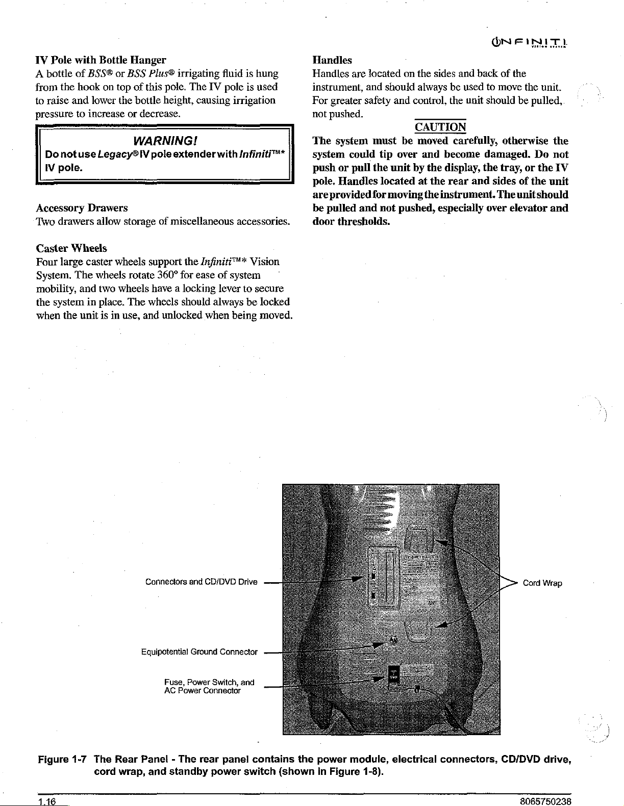
IV
Pole
with
A
bottle
of
from
the
to
raise
and
pressure
Do
IV
to
not
pole.
Accessory
Two
drawers
Bottle
BSS®
hook
on
lower
increase
use
Legacy®
Drawers
allow
Hanger
or
BSS
top
of
the
bottle
or
decrease.
WARNING!
storage
Plus®
this
pole.
height,
IV
pole
extender
of
miscellaneous
irrigating
The
IV
fluid
pole
causing
with
is
hung
is
used
irrigation
Infiniti™*
accessories.
Handles
Handles
instrument,
For
not
The
system
push
pole.
are
be
door
are
greater
pushed.
system
could
or
pull the
Handles
provided
pulled
and
thresholds.
located
and
should
safety
must
tip
unit
located
for
moving
not
on
the
always
and
control,
CAUTION
be
moved
over
and
by
at
pushed,
sides
and
be
the
carefully,
become
the
display,
the
rear
the
instrument.
especially
back
used
unit
and
ON
FINITI
of the
to
move
should
be
otherwise
damaged.
the
tray,
sides
of
The
unit
over
elevator
the
unit.
pulled,
Do
or
the
the
unit
should
and
the
not
IV
Caster
Four
System.
Wheels
large
The
mobility,
the
system
when
the
caster
wheels
and two
in
place.
unit
is
in
wheels
rotate
wheels
The
use,
support
360°
the
for
ease
have a locking
wheels
and
should
unlocked
Infiniti™*
of
system
lever
to
always
when
be
being
Vision
secure
locked
moved.
Figure
1-7
The
cord
Rear
wrap,
Connectors
Equipotential
Panel - The
and
Fuse,
Power
AC
Power
standby
and
CD/DVD
Ground
Connector
rear
power
Connector
Switch,
panel
Drive
and
contains
switch
the
(shown
power
in
Figure
module,
1-8).
electrical
connectors,
CD/DVD
8065750238
drive,
Page 25
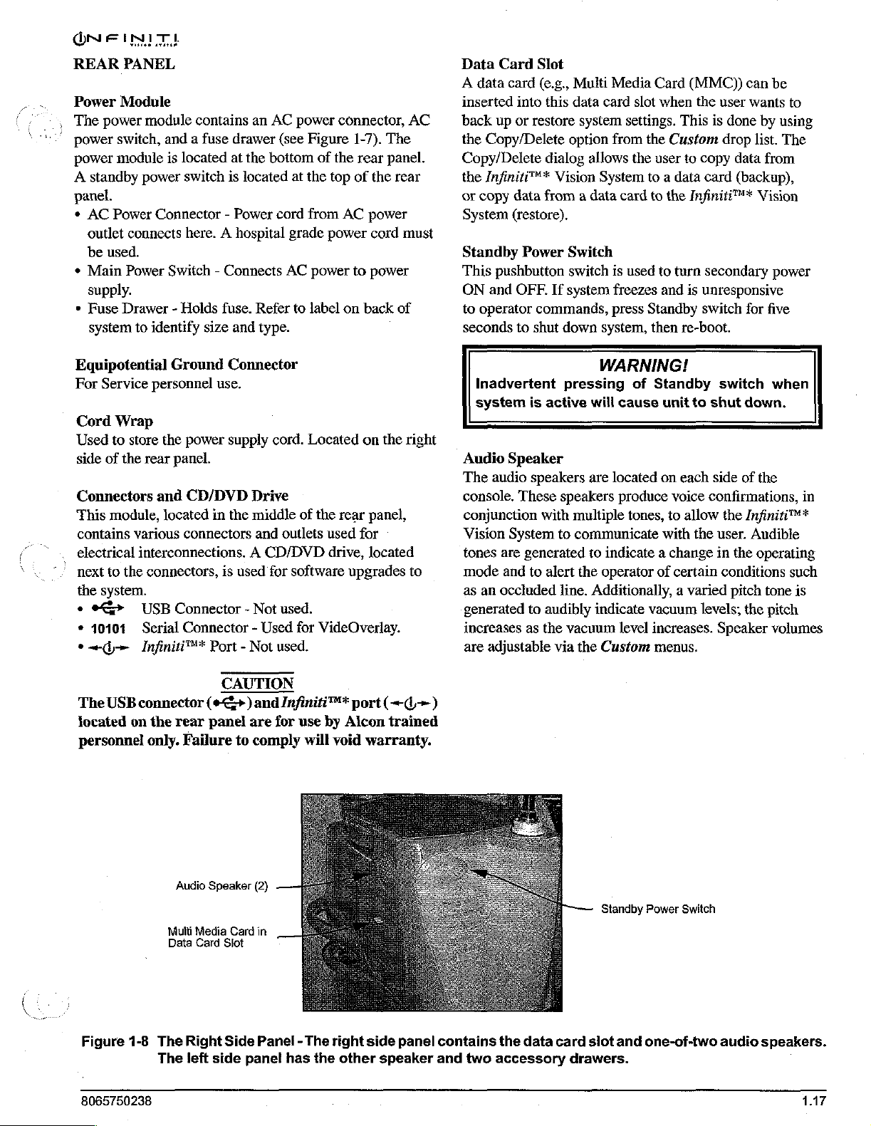
ÖNE
REAR
Power
,
The
power
power
A
INT
Master
PANEL
Module
power
switch,
module
standby
panel.
*
AC
Power
outlet
connects
be
used.
*
Main
Power
supply.
*
Fuse
Drawer - Holds
system
Equipotential
For
Service
Cord
Wrap
Used
to
store
side
of
the
Connectors
“This
module,
contains
various
electrical
next
to
the
the
system.
e
e>
+
10101
ei
rita
module
power
to
identify
personnel
rear
contains
and a fuse
is
located
switch
an
drawer
at
the
is
located
Connector - Power
here. A hospital
Switch - Connects
fuse.
Refer
size
and
type.
Ground
Connector
use.
the
power
supply
panel.
and
CD/DVD
located
connectors
in
the
Drive
middle
and
AC
(see
bottom
at
cord
grade
AC
to
cord.
outlets
interconnections. A CD/DVD
connectors,
USB
Connector - Not
Serial
Infiniti™*
is
used
for
used.
Connector - Used
Port - Not
used.
software
power
connector,
Figure
the
from
of
the
top
AC
1-7).
of
power
power
to
label
on
Located
of
the
rear
used
drive,
upgrades
for
VideOverlay.
The
rear
panel.
the
power
cord
power
back
on
the
panel,
for
located
AC
rear
must
of
right
to
Data
Card
Slot
A
data
card
(e.g.,
inserted
back
the
Copy/Delete
the
or
System
into
up
or
restore
Copy/Delete
Infiniti™*
copy
data
from a data card
(restore).
this
dialog
Standby Power
This
pushbutton
ON
and
OFF.
to
operator
seconds
commands,
to
shut
Inadvertent
system
Audio
The
console.
conjunction
Vision
tones
mode
as
an
generated
increases
are
is
active
Speaker
audio
speakers
These
with
System
are
generated
and
to
alert
occluded
to
audibly
as
the
adjustable
Multi
Media
data card
system
option
allows
Vision
slot
settings.
from
the
System
the
Switch
switch
If
system
is
used
freezes
press
down
system,
WARNING!
pressing
are
speakers
multiple
to
communicate
to
the
line.
vacuum
via
the
of
will
cause
located
produce
tones,
indicate a change
operator
Additionally, a varied
indicate
level
Custom
Card
(MMC))
when
the
This
Custom
user
to
copy
to a data
to
to
and
Standby
then
card
the
Infiniti™*
turn
secondary
is
unresponsive
switch
re-boot.
Standby
unit
to
on
each
voice
confirmations,
to
allow
with
the
of
certain
vacuum
levels;
increases.
menus.
can
user
wants
is
done
by
drop
list.
data
from
(backup),
Vision
for
switch
shut
down.
side
of
the
the
Infiniti™*
user.
Audible
in
the
operating
conditions
pitch
tone
the
Speaker
be
to
using
The
power
five
when
in
such
is
pitch
volumes
„=
The
USB
located
personnel
Figure
8065750238
connector
on
the
rear
only.
Audio
Multi
Data
1-8
The
The
CAUTION
(e+)
panel
Failure
Speaker
Media
Card
Slot
Right
Side
left
side
and
are
to
comply
(2)
Card
in
Panel - The
panel
Infiniti™*
for
use
by
will
void
right
has
the
port
Alcon
warranty.
side
other
(+4)
trained
panel
speaker
contains
and two
the
data
accessory
card
slot
drawers.
Standby
and
Power
Switch
one-of-two
audio
speakers.
Page 26
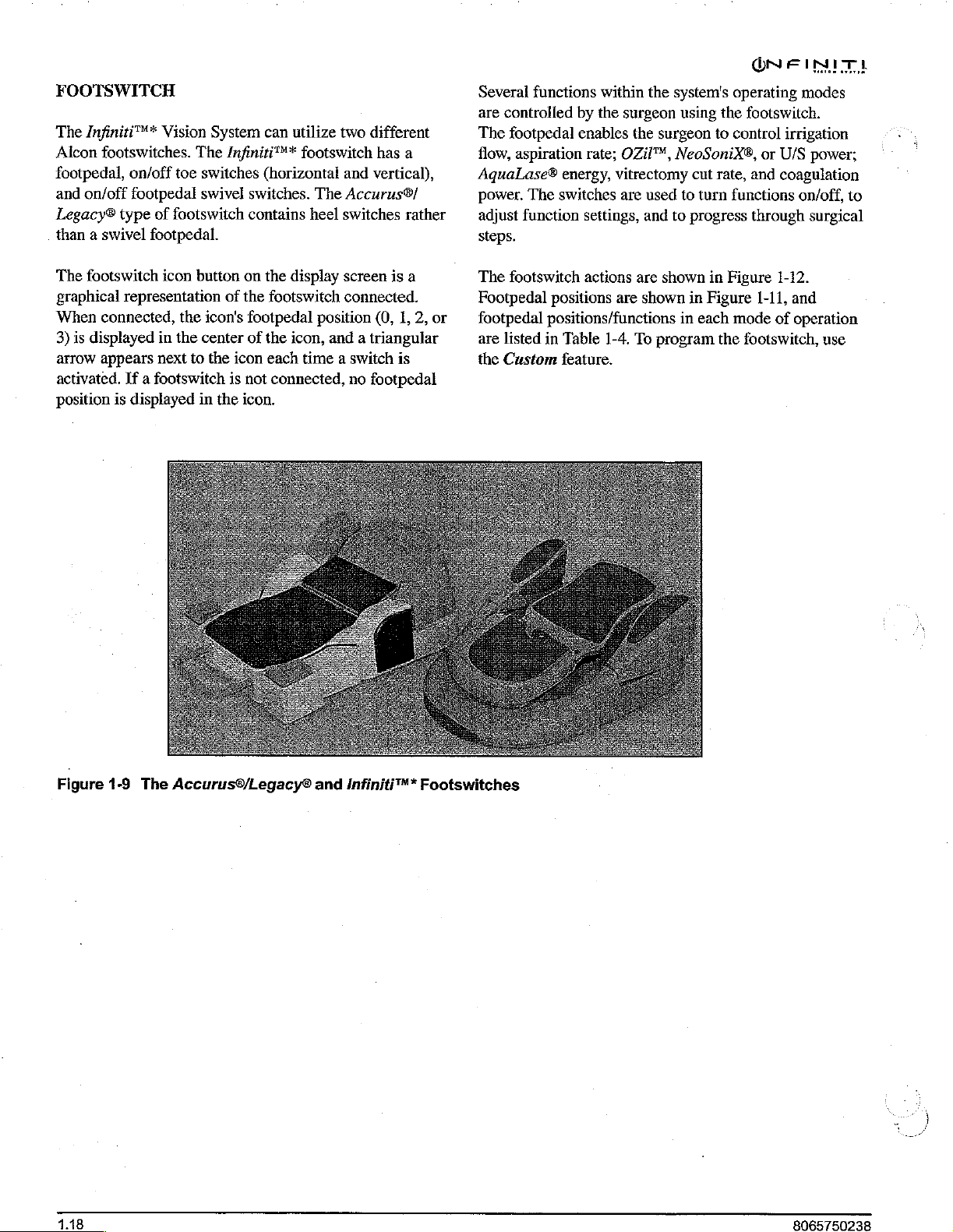
ON
FIN
FOOTSWITCH
The
Infiniti™*
Alcon
footswitches.
footpedal,
and
Legacy®
than a swivel
The
graphical
When
3)
is
arrow
activated.
position
on/off
on/off
footpedal
type
footswitch
representation
connected,
displayed
appears
If a footswitch
is
displayed
Vision
System
The
toe
switches
swivel
of
footswitch
footpedal.
icon
button
the
icon's
in
the
center
next
to
the
in
the
can
utilize
Infiniti™*
(horizontal
switches.
contains
on
the
display
of
the
footswitch
footpedal
of
the
icon,
icon
each
is
not
connected,
icon.
two
different
footswitch
The
heel
has
and
vertical),
Accurus®/
switches
screen
connected.
position
(0,
and a triangular
time a switch
no
footpedal
a
rather
is
a
1,
2,
is
or
Several
are
The
flow,
functions
controlled
footpedal
aspiration
AquaLase®
power.
adjust
The
function
steps.
The
footswitch
Footpedal
footpedal
are
listed
the
Custom
within
by
the
enables
rate;
energy,
switches
settings,
actions
positions
positions/functions
in
Table
the
surgeon
the
surgeon
OZil™,
vitrectomy
are
used
and
are
shown
are
shown
1-4.
To
program
system's
using
NeoSoniX®,
to
to
in
feature.
operating
the
footswitch.
to
control
cut
rate,
turn
functions
progress
in
Figure
in
Figure
each
mode
the
footswitch,
modes
irrigation
or
U/S
and
coagulation
on/off,
through
1-12.
1-11,
and
of
operation
power;
to
surgical
use
Figure
1.18
19
The
Accurus®/Legacy®
and
Infiniti
"*
Footswitches
Page 27
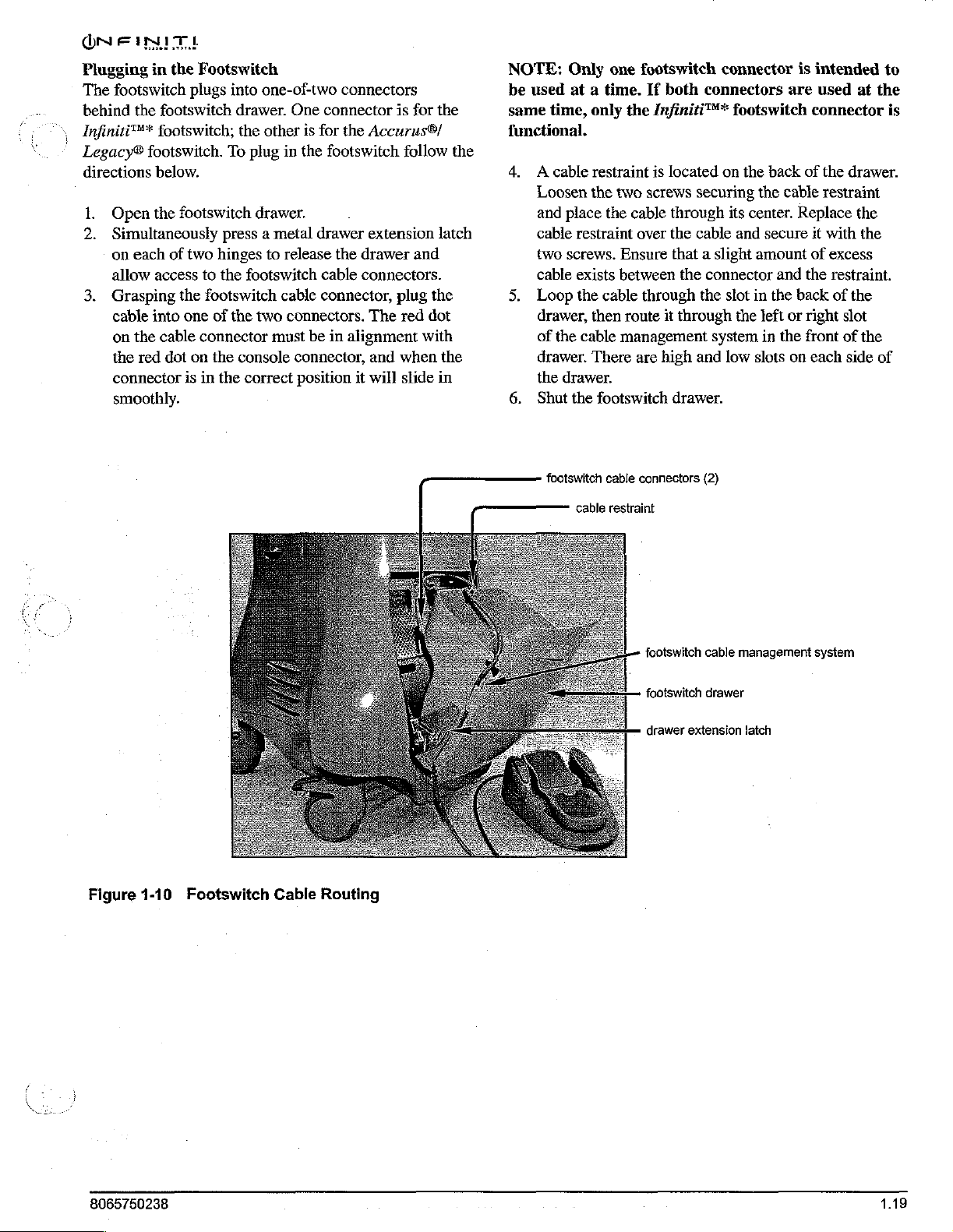
Plugging
The
behind
Infiniti™*
Legacy®
directions
Nr
3.
in
footswitch
the
footswitch.
below.
Open
the
Simultaneously
on
each
allow
access
Grasping
cable
into
on
the
the
red
connector
smoothly.
the
Footswitch
plugs
into
footswitch
footswitch;
drawer.
the
To
footswitch
press a metal
of
two
hinges
to
the
the
footswitch
one
of
the
cable
connector
dot
on
the
console
is
in
the
one-of-two
One
other
plug
in
connectors
connector
is
for
the
footswitch
drawer.
drawer
to
release
footswitch
cable
two connectors.
must
correct
the
cable
connector,
be
in
connector,
position
is
the
Accurus®/
follow
extension
drawer
connectors.
plug
The
red
alignment
and
when
it
will
slide
for
and
dot
with
the
the
latch
the
the
in
NOTE:
be
same
functional.
4. À cable
5.
6.
Only
used
at a time.
time,
Loosen
and
place
cable
restraint
two
screws.
cable
exists
Loop
drawer,
of
the
drawer.
the
drawer.
Shut
the
the
cable
one
footswitch
If
only
the
Infiniti™*
restraint
the
the
cable
then
There
footswitch
is
two
screws
cable
over
Ensure
between
through
route
management
are
connector
both
connectors
footswitch
located
through
the
that a slight
it
high
drawer.
on
securing
cable and
the
connector
the
slot
through
system
and low
its
the
back
the
center.
secure
amount
in
the
the
left
in
slots
is
are
of
cable
Replace
and
the
back
or
right
the
front
on
intended
used
at
connector
the
drawer.
restraint
the
it
with
the
of
excess
restraint.
of
the
slot
of
the
each
side
to
the
is
of
Figure
1-10
footswitch
cable
cable
connectors
restraint
footswitch
footswitch
(2)
cable
drawer
management
system
—
drawer
Footswitch
Cable
extension
Routing
latch
8065750238
1.19
Page 28
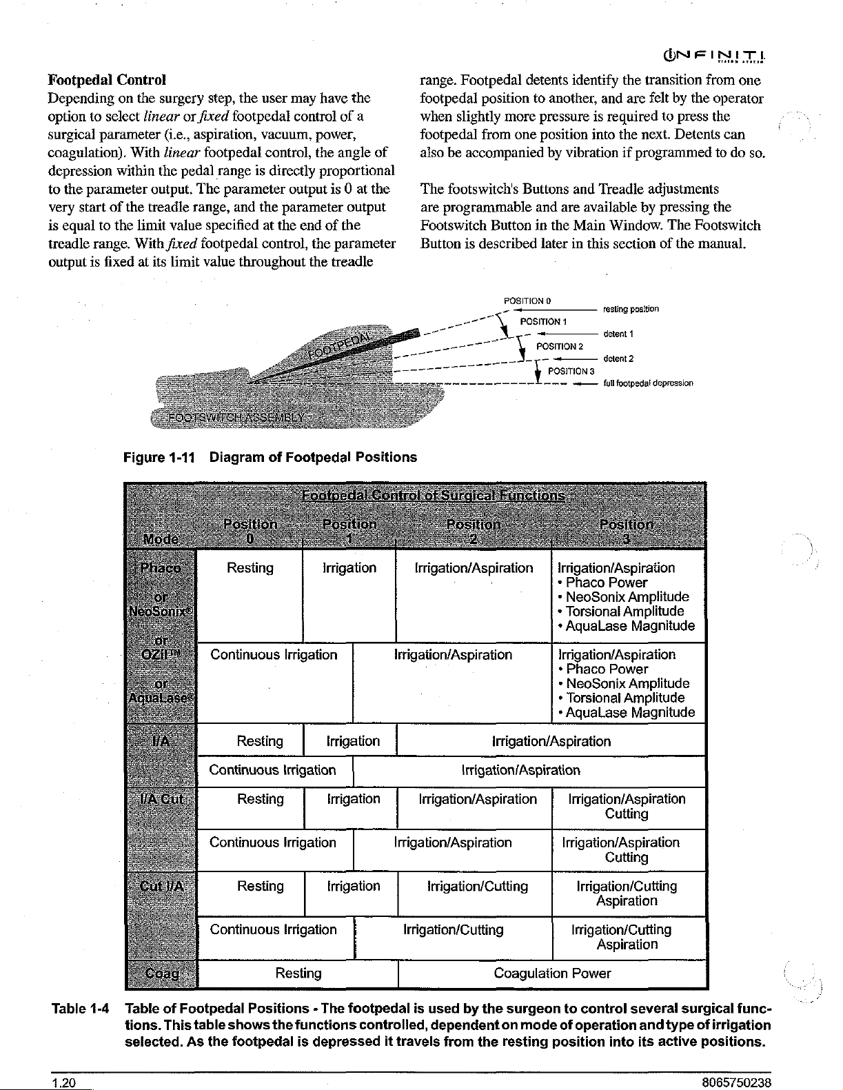
ON
FINITE
Footpedal
Depending
option
surgical
coagulation).
depression
to
the
very
is
equal
treadle
output
Control
on
to
select
parameter
With
within
parameter
start
of the
to
the
range.
is
fixed
Figure
the
surgery
linear
linear
the
output.
treadle
limit
With
at
its
or
fixed
(i.e.,
aspiration,
pedal
The
range,
value
fixed
limit
1-11
step,
the
footpedal
footpedal
range
is
parameter
and
specified
footpedal
value
throughout
Diagram
user
may
control
vacuum,
control,
directly
output
the
parameter
at
the
end
control,
of
Footpedal
have
the
of
a
power,
the
angle
of
proportional
is
0 at
the
output
of
the
the
parameter
the
treadle
Positions
range.
Footpedal
footpedal
when
footpedal
also
The
are
Footswitch
Button
ーーー
position
slightly
from
be
accompanied
footswitch's
programmable
is
described
TN
ニー
プー
detents
more
one
Buttons
Button
POSITION
POSITION
ー
\
identify
to
another,
pressure
position
by
vibration
and
and
are
in
the
Main
later
in
0
1
ペーーーーー
POSITION
———
у
POSITION
-—
the
and
are
is
required
into
the
if
Treadle
available
Window.
this
section
Testing
position
detent
deleni2
3
{ull
1
footpedal
2
transition
felt
by
the
to
press
next.
Detents
programmed
adjustments
by
pressing
The
Footswitch
of
the
manual.
ο
depression
from
one
operator
the
can
to
do
the
so.
Table
1-4
Table
tions.
selected.
of
Footpedal
This
table
As
Resting
Continuous
Resting
Continuous
Resting
Continuous
Resting
Continuous
Positions - The
shows
the
footpedal
Irrigation
Irrigation
Irrigation
Irrigation
Irrigation
Resting
the
functions
is
depressed
Irrigation
Irrigation
Irrigation
footpedal
controlled,
it
Irrigation/Aspiration | Irrigation/Aspiration
irrigation/Aspiration
Irrigation/Aspiration
Irrigation/Aspiration
Irrigation/Aspiration Irrigation/Aspiration
Irrigation/Cutting
Irrigation/Cutting
*
Phaco
*
NeoSonix
*
Torsional
+
AquaLase
Irrigation/Aspiration
*
»
*
Torsional
*
AquaLase
irrigation/Aspiration
Power
Amplitude
Amplitude
Magnitude
Phaco
NeoSonix
Power
Amplitude
Amplitude
Magnitude
lirigation/Aspiration
Cutting
Cutting
Irrigation/Cutting
Aspiration
Irrigation/Cutting
Aspiration
is
used
dependent
travels
from
Coagulation
by
the
on
the
resting
surgeon
mode
Power
to
control
of
operation
position
into
several
and
type
its
active
surgical
of
func-
irrigation
positions.
4.20
8065750238
Page 29

ONEFINITI
Switch
The
to
footswitch
horizontally
activate
Accurus®
switches
switches
Switch
footswitch
The
factory
listed
Control
footswitch
control
various
has
when
/Legacy®
that
that
functions
left
horizonal
default
as
None,
icon
has
six
surgical
left
and
and
vertically,
the
pedal
footswitch
operate
activate
are
and
making
switch
action:
their
and
must
be
programmed
switches
right toe
is
horizontally
when
programmable
Reflux.
functions
Pressing
to
medium
that
functions.
switches
and
footpedal
shifted
is
adjust
left
has
left
and
pressed
selections
the
only
The
other
are
mutually
this
button
the toe
(2),
or
wide
Left
toe
switch
left
for
one
down
for
can
be
programmed
The
Infinitit**
that
operate
switches
or
right.
and
right
vertically,
down.
by
pressing
on
the
display.
switch with
five
switches
exclusive,
allows
switch
another.
the
for a narrow
(1)
foot.
is
pressed
function,
and
that
The
toe
and
the
a
operator
(3),
heel
are
Footpedal
t
foo
for
given a function
the
other
Reflux,
Grade+/-,
if
engaged;
and
disengaged.
the
be
permitted
functions
and
les
switches.
witch
the
same
Cont.
the
footpedal
cannot
mode
allowed
the
swiveled
Accurus.
utilizes
heel
functions.
command
left
already
switch
however,
is
Irr.,
Irr.
Up,
is
be
engaged
If
the
of
operation,
to
engage.
to
be
engaged
are
not
available
and
right
switches
The
plugs
fension
are
given a None
Step+,
Irr.
not
the
footpedal
will
footswitch's
also on
by
the
designated
Step-,
Down,
depressed,
Furthermore,
into
knob
and
switches
until
all
is
depressed,
certain
not
this
with
when
be
end.
and
this
end.
removeable
carrying
switches
the
performed.
The
user.
When a switch
to
another
designation.
Step+/-,
are
other
the
footpedal
Grade+,
None.
any
switch
mutually
switches
may
even
treadle
treadle
cable
handle
depending
if a switch
depressed,
switch,
Choices
Grade-,
may
be
exclusive
are
on
or
may
not
is
some
is
depressed,
is
are
Left
Horizontal/Vertical
Switch
Pressing
{ο
adjust
for a short
size.
different
this
the
It
can
balance
Right
toe
one
function,
button allows
heel
rest
Sì
medium
also be
adjusted
and
Footpedal
switch
is
pressed
and
down
for
the
operator
forward
or
backward
(M),
or
long
(L}
to
attain
feel.
Right
Horizontal/Vertical
right
for
another.
foot
a
Switch
Figure
8065750238
1-12
Footswitches
switch,
and
Left
Heel
below
Switch
Used
with
the
it
Infiniti™*
is
the
Accurus®/Legacy®
Vision
System - Shown
footswitch.
Right
at
Heel
the
Switch
top
is
the
Infiniti™*
foot-
4.21
Page 30
The
following
function
permitted,
when
the
assigned
the
treadle
*
Reflux
The
default
height
pressure.
using
the
sections
is
permitted
and
the
user
treadle
is
depressed,
to a switch
depressed.
reflux
pressure
The
Reflux
Offset
indicate
with
intends
that
reflux
control
menu.
In
all
cases,
reflux
is
not
depressed,
*
Continuous
When a switch
is
toggled,
activates/deactivates.
available
available
and
is
not
available
Irrigation
On/Off
assigned
the
continuous
Continuous
when
the
footpedal
in a Coagulation
whether
the
treadle
to
control
the
function
is
permitted
is
equal
pressure
in
the
available
in a Coagulation
to
Continuous
irrigation
irrigation
is
in
any
step.
each
depressed.
that
must
to
be
engaged
-
to
the
current
can
be
increased
Custom/Doctor
when
the
footpedal
Irrigation
status
immediately
toggling
position,
switch
If
it
function
be
with
bottle
step.
On/Off
but
is
is
is
is
not
*
Cataract
A
switch
(Grade
grade
of
the
Grade
may
+),
cataract
increase/decrease
cataract
AquaLase®
footswitch
If
cataract
assigned,
cataract
cataract
then
switch
pressed
decrease
If
the
cataract
grade
grade
selected,
treadle
grade
when
grade
grade
cataract
is
pressed
for
more
function
highest
grade
will
be
is
currently
the
Increase,
be
assigned
grade
Decrease,
as
decrease
(Grade
grade
is
only
available
steps,
and
is
available
is
depressed.
increase
the
to
the
switch
current
or
is
increase/decrease
grade
increase
for
less
than
will
cataract
increase
selected.
selected
highest
cataract
will
than
1/2
second,
be
activated.
grade
is
selected,
Similarly,
and
cataract
(Grade
+/-).
Footswitch
whether
cataract
grade
pressed,
cataract
is
assigned
be
activated
1/2
second.
then
is
currently
the
if
the
cataract
grade
will
ONE
INET
Increase/Decrease
grade
increase
-),
or
cataract
control
in
phaco
and
or
not
the
the
next
grade
decrease
is
is
or
previous
selected.
If
to a switch,
if
the
If
the
the
cataract
selected,
lowest
cataract
lowest
grade
decrease
be
selected.
cataract
switch
is
grade
and
is
*
Step
Advance,
A switch
back
may
(Step
-),
Coagulation,
from
this
stepping
If
step
advance
is
pressed,
is
selected
assigned
if
the
switch
back
the
in
to a switch,
switch
is
pressed
function
Step
be
assigned
or
step
and
Anterior
or
next
the
surgery
is
pressed
for
will
Back,
Step
as
advance/back
Vitrectomy
sequence.
step
back
is
or
previous
menu.
then
step
for
less
more
than
be
activated.
Advance/Back
step
advance
(Step
steps
assigned,
step
to
the
If
step
advance
than
1/2
1/2
second,
(Step
+),
step
+/-).The
when
current
are
excluded
the
Setup,
switch
step
advance/back
will
be
activated
second.
then
If
the
the
is
step
When a new
parameters
new
cataract
+
Irrigation
A switch
down.
released,
down.
second,
until
function
all
may
When
the
If
the
the
the
switch
is
footpedal
cataract
will
be
updated
grade.
Up,
Irrigation
be
assigned
the
switch
IV
pole
switch
IV
is
pole
will
is
released.
available
positions.
grade
is
with
Down
as
is
pressed
position
pressed
move
Control
in
all
steps
selected,
irrigation
will
and
surgical
those
specified
up
and
immediately
increment
held
for
continuously
of
this
but
coagulation,
for
the
or
irrigation
up
or
more
than
up
or
down
irrigation
and
1/2
in
1.22
8065750238
Page 31

ONE
INT
REMOTE
The
Infiniti™*
be
used
assembly
tray
support
offers
the
controls
CONTROL
in
one
receptacle
the
Scrub
Circulating
non-sterile
setup
from
Do
not
the
unit.
manner.
features
the
remote
sterilize
remote
of
cover
Nurse
from
Nurse
are
control
two
ways.
It
and
operated under
supplied
the
can
in
or
Sterile
sterile
operate
field.
Programmability
functions
which
control.
CAUTION
the
remote
is
wireless
can
be
laid
the
the
disposable
Assistant
Alternatively,
the
remote
and
are not
control
as
and
can
in
its
tray
sterile
pak;
this
access
control
custom
to
the
in
user
accessible
it
will
damage
a
Remote
The
buttons.
of
Control
following
The
each,
and
control key
tone
is
generated
The
remote
top
to
bottom.
corresponds
Vision
display
window,
surgery
bar
are
System
screen
2)
menu.
not
accessible
Keys
describes
following
indicate
or
button
as
control
to
the
is
Each
its
associated
display
are
1)
main
The
Adjust
and
Buttons
the
remote
sections
when
is
pressed, a valid
they
will
are
appropriate.
divided
section
of
into
the
section
screen.
the
window,
The
setup
status/surgery
and
button
with
the
remote.
control
describe
valid.
three
remote
of
three
3)
the
and
items
keys
and
the
function
When a remote
or
invalid
sections
key
from
approximately
the
Infiniti
sections
+
of
control
setup
steps/
in
the
Adjust
the
Figure
8065750238
1-13
The
Remote
rotation
Control - The
in
any
orientation.
remote
The
control
sterile
tray
fits
securely
support
in
cover
its
is
tray
then
assembly
draped
receptacle
over
the
and
remote
allows
and
tray.
1.23
Page 32

¢
Irrigation
The
Irrigation
function
press
rapidly
desired
only
valid
*
Cataract
The
Cataract
screen
not
valid
key
is
progression
The
first
press
simply
selected
five
seconds
as
raises
up
or
height
valid
in
when
Grade
and
when
pressed
press
after
invokes
grade.
Control
they
the
any
during
from 1 to
five
confirmation
Up/Down
Control
IV
up/down
do
on
the
pole 1 cmH20
down, a key
is
reached.
the
Setup
and
dialog
is
Key
Grade
key
lens
removal
any
dialog
it
cycles
the
4,
of
the
Cataract
seconds
the
voice
Each
subsequent
selects
of
the
the
grade.
Keys
keys
touchscreen.
up
is
pressed
The
irrigation
Surgery
displayed.
is
only
valid
surgery
is
displayed.
cataract
and
then
grade
begins
Grade
have
elapsed
confirmation
press
next
cataract
on
the
remote
Each
or
down.
and
held
control
screens,
in
the
setup
steps,
Each
upward
again
key,
or
the
from
the
of
the
of
the
grade,
with
individual
To
move
until
the
keys
are
and
are not
and
is
time
this
in
a
at
grade
first
last
press,
currently
key
within
voice
+
Parameter
The
Parameter
parameters
steps.
border.
left,
and
is
valid
up
or
depressed,
¢
Parameter
The
Parameter
settings
adjustment
and
the
1.
parameter
a
yellow
Parameter
used
to
If a linear/fixed
parameter
to
toggle
Selection
Selection
for
adjustment,
The
current
With
this
right
to
select
when
the
but
Value
Value
in
the
Surgery
arrows
linear/fixed
is
selected
border
adjust
Value
its
indicates
Adjustment
value.
toggle
value
adjustment
the
value
Button
button
and
selection
button
the
the
desired
footpedal
is
invalid
Adjustment
Adjustment
Control
(i.e.,
power,
toggle
buttons.
via the
that
button
between
ONE
is
used
to
select
to
select
Coag
and
is
indicated
user
can
and/or a footswitch
when a dialog
Up/Down
Window
vacuum,
Parameter
the
up/down
is
selected,
up/down
linear
with a yellow
navigate
parameter.
up,
This
is
displayed.
Keys
up/down
keys
that
have
aspiration)
When a surgical
Selection
item
is
selected;
keys
can
either
keys
can
be
and
fixed.
INIT
Vit
down,
button
button
affect
button,
the
then
be
of
the
pressed
is
Parameter
Parameter
up / down
Forward / Back
arrow
Selection
Value
Adjustment
keys
keys
button
BOTTOM
Irrigation
up / down
Control
keys
TOP
Enter
key
Cataract
Backlight
Grade
button
key
(2)
Figure
1.24
1-14
The
Remote
Control
Keys
8065750238
Page 33

*
Forward/Back
'The
Forward/Back
left
and
right
through
«
Surgery
©
is
remote,
key
If
Menu
selected
and
using
the
Back
step
key
Coagulation
step, a Forward/Back
step
relative
vitrectomy
scrolls
Setup
Setup
In
the
to
move
highlighted,
the
button.
fluid
portion
skip
to
The
Forward
information
Save,
to
step
all
the
button;
Screen.
Setup
Screen,
to a Setup
but
If
of
the
vacuum
dialog
etc.).
the
the
key
Arrow
Arrow
steps.
In
the
Forward
is
immediately
do
not
or
Anterior
the
last
selected.
way
to
the
Enter
when a Forward/Back
Step
the
Enter
Forward
the
priming
check.
and
to
Keys
keys
are
used
the
Setup
Step
buttons
the
Surgery
key
screens,
or
Back
selected.
wrap
around.
Vitrectomy
key
will
select
the
non-coagulation
Additionally,
left,
the
system
key
must
be
pressed
button,
key
key
the
must
is
pressed
button
be
sequence,
Back
key
can
also
select a button
to
key
The
is
the
next
and
if
the
will
pressed
during
the
system
be
(e.g.,
OK,
move
will
and
the
when a step
on
the
Forward
current
or
previous
non-anterior
Back
key
select
the
to
invoke
key
is
the
used
be
to
activate
the
draw
will
used
in
an
Cancel,
*
Enter
Key
The
Enter
key
is
only
valid
the
Coag
or
Ant
Vit
step
the
Parameter
when
the
key,
3)
invoke a setup
test
handpiece.)
the
Setup
the
highlighted
Irrigation/Continuous
Controls
button,
Metrics
Setup
screen
window
and
6)
window
Selection
button
when
button
with
has
function
the
the
in
Irrigation
is
selected
select
and
is
selected
button.
Remote
When
status
the
The
installed
A
(LR3)
Four
Control
the
batteries
message
irrigation
message
and a remote
battery
holder
batteries.
of
this
Batteries
in
“Remote
controls
will
disappear
inside
To
manual.
the
each
control
replace
to
do
after
it
has
button,
been
(e.g.
2)
selected
function
Forward/Back
dialogs,
when
with
Reset
Metrics
with
the
remote
Battery
Low”
time a remote
after
key
the
remote
batteries,
the
following:
been
go
to
the
prime
has
been
5)
toggle
the
the
Parameter
to
Parameter
control
will
new
batteries
is
pressed.
holds
refer
1)
selected
Setup
with
the
Back
FMS,
fill,
selected
key,
4)
invoke
between
Irrigation
Selection
zero
when
Selection
are
low,
the
appear
key
is
pressed.
are
three
(3)
AAA
to
Section
select
with
Screen
in
the
below
8065750238
1.25
Page 34

Select
The
of-four
to
operating
factory
the
channel
The
This
on
instructed
To
Remote
remote
channels.
independently
in
preset
Infiniti™*
as
the
Custom/System
selection
of
selection
the
remote
below.
select a remote
System:
1.
Press
the
menu.
2.
Press
the
window.
3.
Press
the
Remote
4.
Hold
the
display
parameter
1 & 2
on
buttons.
5.
Press
the
to
the
new
at
3:00,
6.
Press
the
1-14),
then
Control
control can
This
control
the
same
to
channel
Vision
System
remote.
Settings
four
remote
must
correspond
control.
channel
Custom
System
key
Remote
Control
remote
screen
the
Settings
control
and
value
adjustment
screen).
parameter
channel
and D at
Enter
press
6:00
button
Save
Channel
be
configured
feature
room
four
Infiniti"
or
A.
For
must
allows
area.
Remote
proper
be
window
receive
Set
key
Channel
the
remote
on
the
to
activate
to
bring
dialog
in
codes:
to
the
Infiniti™*
up
button
(see
front
simultaneously
upldown
Simultaneously
selection
(labeled A at
on
on
on
the
the
the
button
screen).
remote
screen.
to
operate
four
remote
"*
Vision
controls
remote
set
to
the
allows
A,
the
B,
C, & D.
channel
channel
Vision
its
drop-down
the
System
to
bring
Figure
of
the
Infiniti
press
its
keys
release
corresponding
9:00, B at
(see
on
one-
controls
Systems
are
operation,
same
selection
as
Settings
up
the
1-15).
(labeled
the
12:00,
C
Figure
To'select:a
Press:
Several:
together;
corresponding
Figure
channel:
buttans 1 :and:2'simtitånesusly
momolits,
relodse
the
then:
1-15
press
te
the
The
buttons:
ihe
key:
new:channel:
Remote
for:
Control
Settings
Dialog
No
additional
is
set,
and
NOTE:
If
controls,
with
unigue
Do
not
sterilize
the
unit.
1.26
steps
only
one
necessary
identify
labels.
the
are
remote
to
the
remote
remote
needed
CAUTION
once
the
channel
is
distinguish
controls
control
remote
stored
between
and
as
it
will
channel
per
unit.
remote
the
units
damage
8065750238
Page 35

ONFINITÀI
HANDPIECES,
Different
required
A
full
and
representative
handpieces,
technique
Following
handpieces,
lens
Phaco
Alcon's
and
extraction
maintain
lens,
These
removal
the
*
OZil™
handpiece
handpiece,
oscillations.
as
torsional
Alcon
handpieces,
for
different
selection
sizes
are
available.
for
tips,
and
needs.
is a general description
tips,
removal
emulsification.
and
infusion
the
procedures.
Ultrasound
phaco
handpieces
step
or
inflate
aspirate
handpieces
of
the
sleeve
Torsional
integrates
and
U/S
handpiece;
handpiece,
representative.
TIPS,
of
information
and infusion
and
enable
disposable
This
AND
tips,
procedural
handpieces,
Please contact your
infusion
Handpieces
The
three
the
the
anterior
the
lens
require
with
bubble
Handpiece - The
all
in
addition
handpiece
for
use
INFUSION
and
infusion
steps
along
regarding
sleeves
of
sleeves
integrate
functions
surgeon
material
no
tubing,
functions
tips
to
chamber,
disassembly
the
suppression
provides
uses
best
performance
recommended
SLEEVES
sleeves
and/or
with
the
for
the
various
used
irrigation,
of
simultaneously
from
the
ultrasonic
OZii™
of
the
ultrasonic
many
are
functions.
tip
styles
Alcon
appropriate
your
specific
to
perform
aspiration
the
lens
emulsify
eye.
other
than
tip,
insert.
torsional
ultrasonic
of
the
same
of
by
the
and
tips
OZil™
your
Do
not
test
NeoSoniX®
BSS®
sterile
in
surgical
and
tip
can
Ensure
irrigating
or
result
that
NeoSoniX®
in
premature
Use
of
OZil™
handpiece
is
including
operator.
Use
AquaLase®
flow
aspiration
and
tissues.
torsional,
not
permitted,
of
and/or
potential
or
operate
handpieces
irrigating
use.
Irreparable
result
test
chamber
solution
handpieces.
an
ultrasonic
repaired
potential
the
OZi!™
handpiece
in
flow
damage
CAUTIONS
U/S,
OZil™
unless
solution
if
run
before
tip
failure
WARNINGS!
NeoSoniX®,
without
and
may
shock
torsional,
the
presence
can
the
or
damage
dry.
is
filled
tuning
handpiece
in
cause excessive
U/S,
Tuning a handpiece
and
or
Alcon
result
hazard
NeoSoniX®,
the
absence
of
to
the
torsional,
tip
is
immersed
distilled
to
the
with
BSS®
OZil™
breakage.
other
U/S,
or
authorization,
in
patient
to
patient
of
reduced
cornea
and
or
in
water
or
handpiece
sterile
torsional,
dry
may
than
the
use
of
a
injury,
and/or
U/S,
or
irrigation
or
lost
heating
other
is
*
Infiniti™*
handpiece
Infiniti™*
tips
or 0.9
and/or
*
Infiniti™*
handpiece
handpiece,
This
handpiece
handpiece.
Ultrasonic
is
used
Vision
mm
ABS®
tips.
NeoSoniX®
integrates
and
(U/S)
Handpiece - This
for
ultrasonic
System
with
TurboSonics®
Handpiece - The
all
functions
in
addition
uses
the
provides
same
applications
1.1
mm
TurboSonics®
tips,
including
NeoSonix®
of
the
sonic
tips
as
the
on
the
flared
ultrasonic
oscillations.
U/S
rooms
Figure
grd
Figure
sasonie
1-16
1-18
νομος
ES
OZi!™
oscilaton
“OS
~
{nfiniti™*
Torsional
NeoSoniX®
Handpiece
Handpiece
8065750238
1.27
Page 36

TurboSonics®
U/S
tips
are
are
attached
handpiece
assisting
needs
styles
Various
+
1.1
original
for
+
0.9
designed
They
and
of
mm
use
mm
are
in
tips
U/S
only
to
its
technigue
U/S
1.1
U/S
to
designed
sleeves.
Family
made
of
to
an
Ozil™
deliver
removal
and
tip
tip
styles
Tips - The
mm
TurboSonics©
with
1.1
Tips - The
allow
of
Tips
medical
grade titanium
torsional,
mechanical
by
aspiration.
preferred
bevels
are
by
are
available
color
coded.
standard
mm
infusion
0.9
mm
entry
through a smaller
for
use
only
U/S,
or
energy
to
Depending
the
surgeon,
(see
ultrasonic
tips.
They
sleeves.
ultrasonic
with
0.9
mm
alloy,
NeoSoniX®
the
lens,
on
various
Figure
tips
are
are
designed
tips
are
incision.
infusion
and
the
1-19).
the
*
Mackool**
U/S
contain a polymer
tip
shaft.
This
provides
¢
Aspiration
feature
the
system
Use
Use
Mismatch
of
combination
create a patient
Read
consumable
additional
Bypass
contain a small
tip’s
wall.
even
during
0.9
mm
1.1
mm
of
settings
all
not
package
Tips - The
tubing
necessary
over
part
thermal
System - Tips with
hole
This
helps
to
occlusion
WARNINGS!
tips
with
0.9
tips
with
1.1
consumable
specially
of
consumable
hazard.
paks
prior
label
adjusted
material
to
Mackool**
the
main
of
the
Mackool**
and
fluidic
in
the
distal
maintain
of
the
tip’s
mm
infusion
mm
infusion
components
components
their
use.
ONE
IM!
ultrasonic
part
tips
of the
tip
advantages.
the
ABS®
portion
flow
main
of
through
port.
the
sleeves.
sleeves.
and
use
for a particular
may
printed
on
the
Figure
Tapered
of
inner
while
tapered
flared
1-19
Standard
with
tip
the
round
shape.
U/S
The
The
Aspiration
the
ABSŮ
portion
feature
of
the
ABS®
Tip - The
the
0.9
mm
and
outer
the
distal
ABS®
tip,
as a straight
and
TurboSonics®
NeoSoniX®
Tips - The
shaft
0.9
1.1
is
the
original,
mm
has a smaller
mm
Bypass System - Tips
contain a small
tip's
wall.
hole
7
tapered
tip
and
diameters
end
tip
has
the
same
tip.
handpieces.
ABS®
the
flared
is
is
equivalent
comparable
the
improved
aspiration
Tips - Shown
TurboSonics®
classical
diameter
with
hole
in
the
-
tip
is a combination
ABS®
tip.
to
to
flared
holding
flow
characteristics
here
tip
U/S
shaft.
distal
The
shaft
straight
tips.
The
force
of
are
tips,
a
samples
Kelman®
which
fo
efficiency.
during
Tips - The
generates
the
conventional
In
the
surgical
Flared
ABS®
port,
providing
middie
of
improving
anterior
also
enhance
Mackool**
ultrasonic
main
of
the
occlusion
charnber,
have
the
performance.
polymer
tips
part
of
U/S
tips
Kelman®
transverse
longitudinal
addition,
ABS®
tons
Series
the
the
procedure.
hole — |
Tips - The
increased
shaft,
Aspiration
contain a polymer
tip
used
holding
thus
allowing
breaks
following
Bypass
U/S
Tips - The
shaft.
with
tips
ultrasound
motion,
bend
allows
flared
tips
force.
smaller
by
reducing
occlusion
System
tubing
the
have a bent
motion,
to
enhance
better
have a larger
They
incisions
outflow
breaks.
feature,
Mackooř*
over
OZi/™
torsional,
shaft
in
addition
cutting
visibility
proximal
narrow
in
and
from
the
Flared
tips
to
further
the
the
U/S,
and
128
Page 37

AquaLase®
The
AquaLase®
rapid
pulses
while
at
the
and
aspirating
©
1.1
mm
Liquefaction
handpiece
Figure
1-20
MicroSmooth™*
Infusion
irrigation
surgery
the
AquaLase®
handpieces.
OZil™
BSI
be
.
following
'
MicroSmooth™*
sleeves
to
(see
Infiniti™*
torsional,
(bubble
correctly
descriptions).
Liquefaction
handpiece
of
fluid
to
perform
same
time
irrigating
the
lens
material
Tip - Used
and
for
use
with
AquaLase®
Infusion
cover
the
the
anterior
Figure
U/S,
handpieces,
Infusion
and
suppression
matched
infusion
chamber
1-21).
OZil™
and
sleeves
NeoSoniX®
to
the
Infiniti™*
Handpiece
utilizes
Liquefaction
warmed
liquefaction
the
from
with
1.1
mm
Sleeves
tip
of
the
of
Infusion
torsional,
insert).
specific
sleeves.
with
some
used
handpieces
Infusion
sleeves
with
paks
high
on
anterior
the
infusion
handpiece
the
NeoSonixX®,
tip
chamber
eye.
AguaLase©
Handpiece
eye
during
are
Ultraflow™*
Infiniti™*
require
sleeves
type
(see
contain
energy
the
lens,
sleeves.
to
provide
used
with
and
UA
U/S,
a
must
the
only
Depending
surgeon,
*
Standard
are the
sleeves
1.1
mm
*
MicroSmooth™*
infusion
original
the
incision.
from
anterior
in
and
tips.
¢
MicroSmooth™*
infusion
original
the
incision.
(green),
to
on
various
MicroSmooth™*
original
are
mm
tips;
tips.
sleeves
infusion
high
infusion
Reduced
this
larger
chamber.
semi-transparent
semi-transparent
sleeves
infusion
Ultra
infusion
Ultra
to
be
be
used
with
the
needs
styles
infusion
available
and
0.9
in
mm
High
(HIS)
sleeves.
sleeves
resistance
shaft
High
blue,
Ultra
have a smaller
sleeves.
sleeves
infusion
used
with
0.9
mm
WARNINGS!
and
technique
of
infusion
Infusion
sleeves.
1.1
mm
(blue),
(purple),
Infusion
have a larger
is
diameter
infusion
to
purple,
Infusion
sleeves
1.1
tips.
Sleeves - High
The
larger
compatible
to
irrigation
creates a more
be
used
to
be
shaft
The
smaller
is
compatible
are
mm
preferred
sleeves
Standard
sleeves
Sleeves - Ultra
tips;
are
available.
Sleeves - These
infusion
to
be
used
to
be
used
with
shaft
diameter
shaft
diameter
with a larger
flow
resulting
stable
are
available
with
1.1
mm
used
with
0.9
diameter
shaft
available
and
than
diameter
with a smaller
in
0.9
mm
by
with
tips;
mm
1.1
the
0.9
than
of
of
mm
(red),
INFUSION
Figure
Infusion
1-21
SLEEVE
~
Infiniti™*
Sleeve
and
BUBBLE
Bubble
SUPPRESSION
U/S
Handpiece
Suppression
INSERT
(BSI)
shown
Insert
with
Use
0.9
mm
U/S
tips
infusion
liquefaction
sleeves.
sleeves
imbalances.
Mismatch
of
settings
combination
create a patient
Read
paks
sleeves.
Mismatching
may
of
not
all
package
prior
to
Use
tips
exclusively
create
consumable
specially
of
consumable
hazard.
their
exclusively
1.1
U/S
potentially
adjusted
labelling
use.
with
mm
U/S
and
with
1.1
mm
tips
and
hazardous
components
for a particular
components
on
the
consumable
0.9
mm
1.1
mm
infusion
infusion
fluidic
and
use
may
8065750238
1.29
Page 38

Ultraflow™*
The
Ultraflow™*
to
maintain
removing
and
of
tip
IT
following
available:
+
Ultraflow™*
The
accepts
an
metal
¢
Ultraflow™*
-
infusion
handpiece
cortical
note
the
aperture.)
and
SP
handpieces
Ultraflow™*
Ultraflow™*
interchangeable
adapter
infusion
Reusable
sleeves
Handpieces
handpiece
chamber
material
band
markings
Some
IT
Handpiece
IT
or
infusion
sleeve.
IT
Handpiece
I/A
tips
can
with
threaded
and
Tips
is
used
pressure
configurations
also
with
be
with
via
aspiration.
on
the
use
infusion
1/A
handpieces
and
consists
sleeve
of a handpiece
tips.
These
as
and
TurboSonics®
used
with
tip
adapter.
irrigation
tips
Interchangeable
they
Threaded
in
I/A
mode
while
(See
Figure
that
identify
of
the
Ultraflow™*
sleeves.
and
tips
contain a built-in
the
Ultraflow™*
The
tips
are
body
do
not
require
Tip
Adapter
silicone
Tips
1-23
size
-
that
IT
Ultraflow™*
tips) - The
handpiece
VA
tip
configurations
Use
of
HA
handpieces
specifications,
specified
may
resultin a fluidic
cause a shallowing
chamber.
Exceeding
with a 0.5
chamber
of
the
VA
tips are
or
OZil"“
SP
Ultraflow™*
with
with a built-in
are
non-Alcon
for
use
the
mm
or
shaliowing
posterior
not
torsional
Handpiece
irrigation
available.
(Single-Piece
SP
consists
tip,
metal
infusion
threaded
WARNINGS!
surgical
that
or
use
with
recommended
larger
capsule.
to
be
handpieces.
reusable
do
not
of
an
Alcon
the
Infiniti™*
imbalance.
or
collapsing
I/A
tip
and/orincarceration
used
with
with
of a single-piece
tip
adapter,
sleeve.
or
disposable
meet
Aicon
handpiece
Vision
This,
in
of
the
level
of
100
may
cause
U/S,
NeoSoniX®,
fixed
or
Various
surgical
not
System,
turn,
may
anterior
mmHg
anterior
ortearing
tip
|
Figure
120º
Tip
Straight
Tip
1-22
Ultraflow™*
IT
handpiece
90°
Tip
and
tips
45º
Tip
Curved
Tip
1.30
Page 39

ÔNEINITI
0.2
0.3
mm
mm
VA
YA
Tip
Tip
Threaded
Tip
0.5
Adapter
mm
WA
Tip
Figure
Figure
1-23
1-24
Ultraflow™*
O-Ring
Large
O-Rings.
Ultraflow™*
|T
handpiece
Extractor
>
O-ring
with
X
tool
with
large
infusion
Small
and
sleeve,
O-Rings
smail
O-rings
reusable
I/A
tip,
and
threaded
tip
adapter
Figure
8065750238
1-25
Ultraflow™*
SP
handpiece
(handpiece
shown
with
.3
mm
45°
tip)
1.31
Page 40

Infiniti™*
The
vitrectomy
cutter
irrigating
bimanual
simultaneous
accessory.
The
handpiece
lubrication
no
oscillating
use
only.
.
Vitrectomy
which
provides
cannula
irrigation.
coaxial
guillotine
probe
is
provided
An
irrigation
is
completely
cleaning
or
vitreous
Probe
is a sterile,
for
aspiration
irrigation
prior
single-use,
in
the
sleeve
is
available
preassembled
surgery.
to
cutter
and
cutting.
pak
to
allow
to
allow
as a separate
and
This
is
intended
vitreous
An
for
for
requires
for
single
Do
not
test
or
the
tip
is
immersed
solution
Irreparable
result
After
the
Prior
sterile
on
that
*
Ifthe
not
the
*
The
position
port
probe.
¢
If
or
the
¢
If
observed
immediately
or
if
run
priming
probe
to
entry
irrigating
the
foot
the
probe
cutteris
move when
probe.
port
infootpedal
is
partially
air
bubbles
exiting
probe.
areduction
distilled
damage
dry.
and before
properly
is
into
treadle
should always remain
the
during
WARNINGS!
operate
water
to
the
eye
solution,
until
is
cutting.
observed
the
closed
are
observed
probe
of
cutting
the
and
replace
vitrectomy
in
BSS®
the
surgical
actuating
and
the
there
to
probe
position 0 or
tip
during
surgical
sterile
or
is in
handpiece
with
surgeon
is
visual
not
fully
is
actuated,
while
idie,
in
the
priming,
capability
procedure,
the
probe.
probes
irrigating
surgical
and
use,
verify
aspirating.
and
the
probe
should
verification
close
in
an
1.
Ifthe
replace
aspiration
or
vacuum
unless
use.
tip
can
that
tipin
step
or
does
replace
open
cutting
the
line
replace
is
stop
Figure
4.32
1-26
Infiniti™*
infiniti™
vitrectomy
Vitrectomy
Irigating
Irrigation
Probe
Cannula
Sleeve
probe
with
irrigating
cannula
and
optional
irrigation
sleeve.
8065750238
Page 41

ON
EF
INET
Bipolar
*
Coagulation
Bipolar
Coagulation
ergonomically
as
to
provide
are
available
+
Bipolar
variety
and
available
Coagulation
of
widestroke.
both
Coagulation
reusable
See
products
Figure
configurations.
your
Alcon
and
1-27
Handpieces
Forceps
designed
precise
to
control
with a wide
Brushes
configurations:
All
disposable
with
and
without
Cords
are
available
representative
accessories.
Single
use
bipolar
are
lightweight
reduce
variety
straight,
and
safety.
of
are
available
hand
tip
curved,
bipolar
cords.
in
disposable
for a complete
brush
and
fatigue
The
as
well
forceps
styles.
in a wide
tapered,
accessories
and
listing
of
are
FLUIDIC
Two
types
offered
one
AquaLase®
of
when
FMS
system
surgical
The
and
irrigating
handpiece,
and
disposal.
fluidic
irrigation
a
BSS®
Device
connection
solution.
for
FMS
FMS
inserted
it
is
into
connections,
setup.
FMS
the
surgical
deposit
chamber,
clear
tubing
irrigating
there
for
inserted
the
is
fluid
This
(clear)
MANAGEMENT
of
Fluidic
use
with
Management
the
ultrasound
Liquefaction
is
automatically
into
console
an
to
monitor
the
single
with
is
to
the
fluidics
contributing
interface
handpiece.
the
handpiece,
irrigation
debris
assembly
non-invasive
and
aspiration
spike
solution.
an
additional tubing
bottle
SYSTEM
System
Infiniti™*
Vision
applications,
Device
the
between
in a sealed
for
For
of
applications.
identified
fluidics
module.
module
to
quick
the
It
is
used
aspirate
and
aspiration
drainage
contains a rigid
pressure
(blue
connection
AquaLase®
(black
AquaLase®
(FMS)
System:
and
another
The
by
the
Inserting
establishes
and
easy
Infiniti™*
to
regulate
debris
console
from
pressure,
bag
for
plastic
sensor,
stripe)
drain
tubing, and
to
the
bottle
Liquefaction
stripe)
balanced
are
for
type
system
the
fluidics
BSS®
the
bag,
of
for
salt
8065750238
Figure
1-28
Management
The
System
Infiniti™*
(FMS)
Ultrasound
Fluidic
1.33
Page 42

INFINITI”*
SOLUTION
When
performing
the
Jnfiniti™*
AquaLase®
BSS®.
This
pulses
from
During
receptacle
arrow
at
turn
to
To
avoid
overtighten.
To
remove
counterclockwise
The
spike
the
AquaLase®/BSS®
AquaLase®
balanced
solution
the
the
setup
on
the
12
secure
damaging
the
on
handpiece.
AQUALASE®
BOTTLE
Vision
tip
the
o'clock
it
in
bottle,
the
BALANCED
an
AquaLase®
System
is
of
procedure
front
position
must
salt
solution
emitted
the
handpiece.
the
of
the
console,
position,
in
CAUTION
the
bottle,
press
it
in
before
black-striped
pulling
bottle
tubing
and
liquefaction
be
equipped
bottle
containing
warm
high
bottle
is
inserted
with
and
turned
take
and
turn
it
out
from
is
inserted
then
connected
SALT
procedure,
with
an
energy
into
its
alignment
clockwise
care
not
its
receptacle.
into
to
the
its
1/4
to
CONSUMABLE
The
family
combinations
handpiece
AquaLase®
Balanced
Infiniti™*
be
used
Please
complete
information
Infiniti™™*
important
NOTE:
in
the
(DFU)
follow
Custom
To
better
surgeons
needs.
more
of
tips,
Salt
Vision
once
contact
up-to-date
paks
to
Han
operator's
supplied
the
DFU.
Pak®
serve
to
Please
information
PAK
CONFIGURATIONS
Infiniti™*
of
fluidic
infusion
complete
Solution.
System
and
then
your
prior
contain
read
inconsistency
with a consumable
Configurations
our
specify a Custom
contact
on
paks
management
sleeves,
paks
include a bottle
Consumable
during
discarded,
Alcon
Sales
listings,
to
initial
Directions
and
understand
exists
manual
customers
your
Alcon
how
to
WARNINGS!
consist
systems
and
other
items
surgery
unless
representative
and
for
in-service
use
of
Alcon
for
the
between
and
the
we
offer
Pak®
for
Sales
design
your
of
various
(FMS),
components.
of
AquaLaseo/
used
with
are
designed
labeled
paks.
Use
DFU's
Directions
pak
the
their
representative
own
otherwise.
for
All
(DFU).
the
or
opportunity
own
Custom
It
prior
to
instructions
For
accessory,
individual
for
Pak®.
the
to
is
use.
Use
for
Figure
1-29
The
AquaLase®
Bottle
Balanced
Salt
Solution
Mismatch
of
settings
combination
create a patient
Don't use
Sterile
reused!
These
time
The
equipment
disposables
system.
disposables
create
to
have
equipment
voidance
prevailing
In
all
contained
understood
configurations.
of
consumable
not
of
paks
that
disposable
(Accreditation
components
use
only; do
constitutes a complete
Use
of
may
potential
contributed
under
of
the
hourly
cases,
in
the
the
prior
specially
consumable
hazard.
have
medical
Manual
have
not
reuse.
used
in
conjunction
disposables
affect
hazards,
system
to
contract,
contract
rates.
instrument
manual
to
components
adjusted
components
exceeded
devices
for
been
other
and
if it
the
malfunction
could
and/or
setup
should
using
and
for a particular
expiration
should
Hospitals,
designed
with
performance
is
result
invoicing
be
any
not
1982.)
for
the
Alcon
surgical
than
Alcon
determined
of
in
instructions
thoroughly
of
the
use
may
date.
be
one
and
the
the
at
pak
Read
all
package
consumable
paks
label
prior
material
to
their
printed
use.
on
the
2NA5750028
Page 43

NFINITE
Infiniti™*
When
of
used.
+
performing a phacoemulsification
the
Infiniti™*
The
Fluidic
Management
assembly
(striped)
drainage
the
FMS
Infiniti™
surgical
+
U/S
Tip
the
ultrasonic
the
all-in-one
wrench
*
Infusion
sleeve
into
fluidic
suppression
from
fits
the
balance.
included
*
Test
Chamber - The
cap
that
functional
handpiece
U/S
pak
Fluidic
U/S
can
Management
family
contain
System
consists
of
irrigation
tubing, a plastic
bag
(maximum
into
its
console
fluidic
system,
setup.
with
Tip
Holder/Wrench - The
handpiece.
tip
wrench/assembly,
the
tip.
Several
Sleeve
eye,
to
with
over
the
protection
One
insert
(BSI); a second
be
used
BSI - This
handpiece
to
infusion
with
test
fits
over
the
handpiece
irrigation
and
and
instrument
System
procedure,
of
paks
with
handpiece
all
the
items
listed
(FMS) - This
(clear)
and
reservoir/pump
capacity
receptacle
allowing
Securely
of
500
establishes
quick
tighten
then
tip
designs
single-piece
tip
to
provide
the
surrounding
sleeve
contains a bubble
infusion
the
I/A
handpiece/tip.
chamber
aspiration
prior
is a small
tip
to
facilitate
check
to
surgery.
Paks
below:
single
aspiration
device, and
cc).
Inserting
the
and
easy
tip
attaches
the
tip
remove
are
available.
silicone
irrigation
tissues,
sleeve
elastomeric
a
of
the
one
tip
with
the
and
is
is
a
to
Fluidic
U/S
Tip
§
infusion
Test
Chamber
VA
Tip
Tray
Support
Management
with
Tip
Holder/Wrench
Sleeve
with
Wrench
Cover
System
BS!
(FMS)
*
I/A
Tip
securely
remove
+
Tray
plastic
and
support
the
tray
during
+
Directions
removal
Wrench - A separate
fasten
the
I/A
tip
the
tip
when
the
Support Cover - The
bag
that
is
placed
arm.
The
cover
to
provide
storage
surgery.
for
Use
(DFU) - Instructions
of
pak
contents
wrench
to
its
surgery
tray
support
around
is
used
for the
(not
shown).
is
required
handpiece,
is
completed.
cover
the
instrument
to
form a pouch
handpiece
for
to
and
also
to
is a sterile
tray
in
and
tubing
setup
and
Figure
1-30
Management
Contents
System
of
Pak
the
(parts
Infiniti”*
not
to
scale).
U/S
Fluidic
8065750238
1.35
Page 44

ÓN
FINI
Infiniti™*
When
the
AquaLase®
AquaLase®
items
*
Fluidic
assembly
(blue
a
plastic
(maximum
its
system,
¢
AquaLase®
AquaLase®
performing a lens
handpiece, a single-use
pak
is
listed
below:
Management
consists
striped),
and
reservoir/pump
capacity
console
receptacle
allowing
Liquefaction
Holder/Wrench - The
handpiece.
tip
wrench/assembly,
tip.
*
Infusion
over
eye,
included
Securely
Sleeve - This
the
handpiece
and
fluidic
to
be
balance. A
used
Fluidic
extraction
used.
This
System
of
irrigation
AquaLase®
of
500
establishes
quick
and
tip
tighten
then
single-piece
tip
to
with
Management
pak
can
(FMS) - This
(clear),
(black
device,
and a drainage
cc).
Inserting
easy
Tip
with
attaches
the
tip
remove
provide
second
the
I/A
System
procedure
with
Infiniti™*
contain
all
the
single
aspiration
striped)
tubing;
bag
the
FMS
the
Infiniti™*
surgical
integral
to
the
with
the
wrench
silicone
irrigation
infusion
handpiece/tip.
fluidic
setup.
Tip
AquaLase®
the
all-in-one
from
sleeve
into
the
sleeve
-
Paks
into
the
fits
is
Fluidic
Management
AguaLase©
integral
Tip
Infusion
Sleeve
Test
Chamber
VA
Tip
Wrench
System
Liguefaction
Holder/Wrench
Tip
(FMS)
with
*
Test
Chamber - The
cap
that
fits
functional
handpiece
*
I/A
Tip
Wrench - A separate
securely
remove
*
Tray
plastic
and
the
during
*
AguaLase©
fasten
the
Support Cover - The
bag
support
tray
to
surgery.
Liguefaction
*
Directions
removal
of
test
over
the
handpiece
irrigation
and
tip
that
arm.
provide
and
instrument
the
I/A
when
the
is
placed
The
storage
Balanced
solution.
for
Use
(DFU) - Instructions
pak
contents
chamber
aspiration
prior
wrench
tip
to
its
surgery
tray
around
cover
is
for
Salt
Solution
(not
shown).
is a small
tip
to
facilitate
check
to
surgery.
is
handpiece,
is
completed.
support
used
the
cover
the
instrument
to
form a pouch
handpiece
Bottle
elastomeric
a
of
the
required
and
also
is a sterile
and
-
for
setup
to
to
tray
in
tubing
and
Figure
Fluidic
1-31
Contents
Management
Tray
Support
AquaLase®
of
System
Cover
Balanced
the
Infiniti™*
Pak
Salt
(parts
Solution
AquaLase®
not
to
scale).
Bottle
1.36
Page 45

ÓN
FINIT
I
FRONT
The
touch
above
swivels
position
Control
located
active
area.
two
pushbuttons
display
down
and
buttons.
can
the
buttons
desired
complete,
press
buttons
push-and-release
activate a function.
DISPLAY
Infiniti™*
screen
the
and
touch
There
basic types
arrow
momentary
press
up/down
adjustment
the
with a single
Vision
has a flat,
console.
rotates,
for
storage.
buttons
within
screen
on
screen:
buttons
The
and
arrow
until
and
he
momentary
For
are
the
are
the
up/
user
hold
the
can
PANEL
System
non-glare
ease
and
of
is
to
it
folds
AND
front
of
viewing
down
TOUCH
display
surface,
panel
and
the
display
into a protected
SCREEN
and
is
mounted
panel
.
The
Infiniti™*
indicate
button
invalid
its
There
Surgery
*
*
button
or
remote
button
icon
symbol
are
screens,
The
Setup
priming
handpiece.
Surgery
each
of
the
touch screen
allows
the
step.
+
Dialogs
from
the
etc.) or
Dialogs
settings,
There
when
situation,
Setup
pressing
is
the
screen.
Vision
activation.
control
results
is
three
types
and
screen
the
fluidic
screens
current
buttons
user
are
displayed
Custom
enable
doctor
another
user
needs
or
to
indicate
System
Activation
button
in
an
invalid
ghosted
of
display
Dialogs.
is
used
management
contain
surgical
(or
to
adjust
as a result
drop
list
the
Metrics
the
user
to
settings,
class
of
to
be
progress
emits
of a valid
results
in a valid
key
to
indicate
screens:
to
prepare
system
special
footswitch
the
and
dialogs
surgical
procedures.
settings
of
(i.e.,
System,
or
Footswitch
view
and
some
that
advised
or
on a function
an
audible
touchscreen
key
tone,
and
an
invalid
the
Setup
for
surgery;
and
testing
settings
Pressing
or
remote
for
his
current
selecting
About,
button.
modify
surgical
are
displayed
warned
system
settings.
tone
to
tone;
an
sometimes
function.
screen,
i.e.,
the
for
the
control)
an
option
Doctor,
of
a
in
the
Figure
8065750238
1-33
*
Custom
Navigating
Pulse
is
enabled/disabl
the
led
through
Infiniti™*
the
User
Advanced
Screens
tab
on
the
Doctor
Settings
dialog.
1.37
Page 46

SETUP
The
SCREEN
Setup
screen
occurs:
+
The
system
successful.
+
The
screen
button
+
The
than
+
The
the
he
from a Surgery
EMS
is
Coagulation.
handpiece
user
indicates
selects
the
+ A handpiece
handpiece
* A valid
is
FMS
screen.
The
Setup
screen
top
is
the
Main
Window,
1.
Main
The
are
(see
in
most
later.
Window
Main
used
to
Figure
areas
and
Window
set
1-34).
AND
is
displayed
is
powered
is
explicitly
removed
tip
is
on
Setup
screen.
is
selected
not
tuned.
is
inserted
is
divided
Window,
below
that
consists
up
the
system
The
as
the
Surgery
ITS
FUNCTIONS
when
up
and
invoked
screen.
while
in a surgery
changed
the
resulting
in a surgery
while
into
below
are
the
of
buttons
and
Setup
Main
Main
one
of the
following
initialization
by
pressing
is
the
screen
in a surgery
popup
the
user
three
that
is
Setup
then
Window
Window
screen
message
screen
and
is
in a surgery
sections.
the
Setup
Steps.
and
readouts
perform
surgery
is
the
discussed
Setup
other
and
that
the
At
the
Status
that
same
1.1
Doctor
The
Doctor
doctor.
of
all
at
the
contains
position
allows
remaining
selected
When a doctor
following
¢
The
When
the
top
ali
from
the
doctor
drop
Name
Name
doctors
of
the
the
user
doctors
occurs:
list
displayed.
+
The
surgical
tip
are
selected
-
The
I/A
tip
-
If
no
handpiece
tip,
and
procedure
the
doctor,
-
If
the
currently-selected
not
tuned,
The
tip
and
the
doctor
procedure
the
doctor
-
If
the
currently-selected
selected
handpiece
procedure
the
selected
+
The
Cataract
button
pressed,
entered
list
Alcon
the
top
to
add a new
in
the
is
selected
collapses
this
is
the
defaults.
is
the
will
be
third
displays
in
and
handpiece,
in
accordance
is
changed
is
connected,
are
or
defaults
the
selected
procedure
for
the
selected
do
change, a dialog
that
the
tip
and
changes
surgical
Grade
to
handpiece
is
set
the
button
Alcon
displays a drop
the
system.
Settings
Listed
Add
Doctor
doctor
listed
with
position.
(other
than
the
selected
phaco
tip,
with
to
that
last
the
changed
selected
handpiece
handpiece
change
handpiece.
and/or
procedure
handpiece
tip
do
not
that
last
to
the
ONE
IMIDE
currently-selected
list
The
first
doctor
doctor,
in
the
selection
to
the
the
most-recently-
Add
doctor
procedure,
the
following:
used
surgical
to
those
in
Doctor
is
connected
does
to
those
is
displayed
is
tuned,
change.
used
by
and
tip.
doctor’s
which
second
list.
The
Doctor),
name
and
by
the
handpiece,
last
used
Settings.
not
change.
last
used
If
the
tip
notifying
have
changed.
the
The
the
doctor
default.
which
doctor.
the
is
I/A
by
but
by
or
for
2.
Setup
Figure
1.
Status
3.
1-34
Main
Window
Window
Setup
Steps $ A
Functional
1.1
Areas
Doctor
of
the
Name
1.2
Handpiece
Setup
Type
1.3
Screen
Tip
Type
1.4
Procedure
Type
1.5
Cataract
Grade
1.9
Custom
1.8
Footswitch
1.7
Metrics
or
VA
1.6
Irrigation
Button
Display
Tip
Type
Controls
Button
ANAATANDAR
Page 47

Add
Doctor
When
Add
list, a dialog
\
can
enter a doctor’s
'
the
alphanumeric
typed
and
disappears
default
anew
current
the
1.2
The
parameters
doctor
doctor
top,
just
Handpiece
Handpiece
selected
NeoSonix®
(AqL).
Pressing
available
selected,
*
The
drop
displayed.
«
The
surgical
last
used
current
with
the
procedure,
'
During
correspond
selection
started.
The
system
torsional,
only
one
third
connector
be
connected
NeoSonix®,
If
handpieces
/
NeoSonix® / U/S
handpieces
The
message
button;
one
however,
of
the
Doctor
window
the
OK
and
the
is
successfully
and
below
Type
Type
surgical
(Neo),
this
surgical
the
following
list
collapses
tip
by
the
surgical
steps
and
setup,
the
to
the
of
the
handpiece
has
two
NeoSoniX®,
connector
for
at
or
U/S
are
detected.
can
handpieces
is
selected
with
name
keypad.
button
doctor
(names
is
entered
Add
button
handpiece:
Ultrasound
button
handpieces.
and
procedure
doctor
steps
associated
the
first
handpiece
installed
surgical
and
can
an
AquaLase®
the
same
from
keyboard
in
the
designated
When a doctor’s
is
pressed,
name
is
are
not
saved,
in
the
Doctor.
displays
OZil™
(U/S),
displays a drop
When a handpiece
occurs:
and
the
selected
for
the
selected
in
the
Surgery
with
the
step
is
entered.
selection
handpiece.
is
disabled
connectors
U/S
handpieces;
be
used
at
time
as
handpiece.
plugged
connectors,
into
both
the
Remove a handpiece.”
be
dismissed
U/S
power
is
by
will
removed.
not
the
doctor
appears.
drop
The
box
name
the
dialog
saved
case-sensitive).
he
becomes
third
the
torsional
or
AquaLase®
window
with
Alcon’s
the
position
currently-
(OZil),
list
of
handpiece
are
changed
to
handpiece.
Menu
are
newly
selected
will
automatically
Automatic
when
the
case
for
OZi/™
however,
one
time.
There
handpiece,
an
OZil™
of
the
message
and
torsional,
OZi/™
“Two
will
pressing
the
be
available
OK
user
using
is
When
from
is
is
those
The
replaced
is
is
a
it
can
appear.
until
1.3
Tip
Type
The
Tip
Type
button
surgical
list
tip
*
+
*
tip.
of
available
is
selected,
The
drop
The
Procedure
doctor
If
a
either
for
there
dialog
to
dialog.
list
are
will
save
If
the
When
the
tips
the
collapses
selected
unsaved
be
or
dialog
changed.
1.4
Procedure
The
Procedure
Type
Type
selected surgical
button
the
the
button
displays a drop
selected
following
*
The
*
If
there
dialog
save
If
the
Procedures
1.5
Cataract
The
Cataract
cataract
drop
are
will
or
discard
dialog
and
using
grade:
handpiece
happens:
list
unsaved
be
can
Grade
Grade
displays a drop
new
cataract
*
The
is
displayed.
+
The
*
Surgical
cataract
specified
grade
drop
list
cataract
step
grade
for
collapses
displayed
is
be
1,
list
collapses
grade
parameters
the
displays
pressed,
for
the
following
and
Type
is
changed
handpiece
changes
displayed
discard
is
canceled,
button
procedure
list
tip.
and
changes
these
changes,
canceled,
customized
the
Copy/Delete
button
2,
3,
or
4.
of
the
four
is
selected,
and
is
enunciated.
are
updated
new
cataract
the
currently-selected
this
button
selected
displays a drop
handpiece.
occurs:
the
to
giving
the
changes,
displays
name.
of
the
available
selected
to
surgical
the
When
that
and
tip.
the
user
or
surgical
the
currently-
tip
last
parameters,
the
just
pressed,
procedures
When a procedure
the
procedure
to
giving
or
the
procedure
by
surgical
the
just
pressing
parameters,
user
the
cancel
is
the
function.
displays
When
that
with
the
selected,
cataract
the
following
the
selected
are
dependent
the
currently
grades.
cataract
parameter
grade.
When
is
displayed.
used
by
option
cancel
tip
is
this
is
selected,
is
selected.
option
the
dialog.
not
changed.
Custom
selected
this
button
When
occurs:
grade
upon
values
a
the
the
not
for
a
to
a
the
8065750238
1.39
Page 48

1.6
Irrigation
+
Irrigation/Continuous
-
Pressing
readout
and
back
can
also
on
the
The
Patient
number
patient's
Custom/Doctor
than
other
corner
Avoid
with
the
irrigation
and
possible
*
Irrigation
visual
by
the
position.
s
Bottle
height
Controls
the
bottle
from
"Irrigation"
to
"Irrigation"
be
activated
next
page.
Eye
Level
of
centimeters
eye
is
located.
menu.
0,
“PEL=
of
the
box.
setting
indication
fluidics
Height
readout
the
patient
above
pressure
underventing.
Pressure
of the
mechanism,
and
is
representative
patientabove
Adjustment
Irrigation
height
readout
to
"Continuous
again.
several
(PEL)
below
The
PEL
When
xx”
is
displayed
WARNING!
the
FMS
than
indicated
Bar
Display - This
irrigation
irrespective
and
PEL
will
Continuous
other
ways
readout
the
the
Arrows-
indicates
FMS
is
programmed
PEL
in
the
FMS.
will
result
on
pressure
of
the
Indicators
toggle
Irrigation"
irrigation
as
described
that
the
is
set
to a value
the
lower-right
Operating
in a lower
the
display,
bar
display
as
measured
of
the
IV
The
bottle
actual
bottle
the
the
in
pole
is
the
a
height,
are
change
Irrigation
Irrigation
IV
bottle
irrigation
interface
irrigation
from
Irrigation
or
lowering
Default
cm from
of
the
Vitrectomy
is
measured
to
the
results
power
unit
is
automatically
Continuous
Continuous
surgical
the
eye
respective
pressed
position 0 to
FMS
patient’s
in
loss,
turned
the
irrigation
Control
operates
to
the
valve
device
begins
pressure
the
height
the
center
aspiration
mode
from
maximum
bottle
Irrigation
irrigation
steps
during
to
adjust
FMS
is
is
flowing
IV
for
eye.
off
using
retracts
and
surgery
to
the
PEL.
The
the
IV
pole
pressure
on a gravity-feed
to
the
normally
inserted.
when
position
is
increased
pole
that
Ultrasound
of
the
pressure
it
is
55
cm.
the
FMS
Maximum
irrigation
position
the
to
its
is
available
allows
for
by
value
handpiece.
closed
In
most
the
1.
or
decreased
holds
the
and
I/A
drip
chamber
sensor;
Patient
aspiration
bottle
pressure.
is
maintained;
Standby
storage
in
continuous
opening
adjustment
height,
when
footpedal
the
and
and
readout.
principle
The
console's
the
modes
switch,
position.
of
irrigation
modes
to
the
for
Anterior
Eye
Level
pressure
height
of
In
the
however,
the
all
applicable
irrigation
irrigation
arrows
thus
from
the
fluidic
operation
transitions
by
raising
bottle.
is
95
center
(PEL)
sensor
110
cm
event
of
if
the
IV
pole
of
valve.
Figure
1.40
1-35
BOTTLE
center
the
round
sensor
HEIGHT
of
the
aspiration
to
the
MEASUREMENT
drip
chamber
patient's
to
pressure
eye.
the
patient's
sensor
-
Bottle
in
height
eye.
the
Default
FMS.
for
gravity-fed
bottle
PEL
is
height
measured
irrigation
is
from
95
is
cm
the
measured
above
aspiration
the
from
the
center
pressure
of
Page 49

Changing a doctor
irrigation,
tubing
solution.
or
Coagulation
The
Continuous
allowing
between
Continuous
continuous
irrigation
"Continuous
using
the
four
-
Press
the
bottle
~
Use
the
remote
select
the
Irrigation
the
Enter
key
-
Program a footswitch
Irrigation
function,
footswitch
-
Custom/Doctor/General
be
When
range 1 is
NOTE:
“
turn
|
to
sterile
turned
footpedal
of
the
close
On
is
other three
continuous
eliminated,
Before
continuous
the
irrigating
handpiece.
or
handpiece
exchange
handpieces
irrigation
modes.
irrigation
can
feature
be
Irrigation" and
methods
described
height
readout
control's
window
on
the
remote
button
then
button.
to
activate
depressed.
irrigation
switching
irrigation
irrigation
solution
It
methods.
and
valve
shuts
off
continuous
of
irrigation
without
is
not
is
toggled
back
to
and
loss
of
irrigation
available
normally
from
"Irrigation"
"Irrigation"
below:
on
the
display.
Parameter
on
the
Selection
display,
control.
for
the
Continuous
press
down
on
the
tab/Continuous
continuous
can
be
turned
is
on,
footswitch
Irrigation
irrigation
off
ranges 2 & 3 are
handpieces
off,
and
from
it is
after
exiting
prevent
flowing
excess
out
aspiration
in
Setup
turned
off.
again
button
then
press
designated
can
when
using
one
treadle
expanded.
advised
of
the
the
to
eye,
BSS®
to
by
to
the
1.7
Metrics Display
The
Metrics
during
During
the
metrics
and
Average
the
metrics
and
Average
Cumulative
pressed,
readouts
Reset
1.8
Footswitch
The
Footswitch
the
currently-installed
display
lens
removal
Ultrasound
figures
Power.
figures
Magnitude.
Dissipated
the
Metrics
can
be reset
is
pressed.
shown
shown
Button
button
Accurus®/Legacy®
position
footswitch.
box
When
Buttons
dialog
the
footswitch.
dialogs
on
(0,
1,
2,
or
Right/left
whenever a momentary
the
Footswitch
dialog
(see
(see
user
Figure
to
view
1-37)
and
Switching
is
performed
the
viewing
screen.
is
available
steps
and
NeoSonix®
During
For
Energy.
dialog
to
O.
in
(see
Figure
in
this
box
an
AquaLase®
are
AquaLase®
the
OZil™
When
is
displayed, and
The
display
is a graphical
footswitch
footswitch).
3)
is
displayed
and
The
up/down
switch
Button
Figure
modify
between
by
is
pressed,
1-36)
or
appear.
These
the
current
the
pressing
the
the
surgery
1-38
on
next
surgical
procedures
display
U/S
procedure
Time,
mode
the
Metrics
the
will
close
representation
(either
Infiniti™*
current
in
the
arrows
is
footpedal
center
appear
activated.
the
Footswitch
Footswitch
dialogs
settings
Buttons
and
corresponding
screen
page).
Time
Pulses,
it
shows
box
metrics
when
of
or
of
the
in
the
Treadle
allow
of
the
Treadle
tab
is
Figure
Pressing
corresponds
ㆍ
the
Buttons
here
is
the
to a switch
that
can
8065750238
1-36
FOOTSWITCH
the
Footswitch
to
the
tab
activates
Infiniti™
Button
connected
one
*footswitch.
activates a drop-down
be
selected.
BUTTONS
pulls
DIALOGS
up a dialog
footswitch.
of
these
dialogs.
Pressing a button
list,
with
that
Pressing
Shown
next
functions
Figure
-
Pressing
corresponds
the
here
screen
own
DÌ
1-37
the
Treadie
is
the
allow
personal
FOOTSWITCH
Footswitch
to
the
connected
tab
activates
infiniti™*
you
footswitch.
to
adjust
preferences.
TREADLE
Button
one
of
the
treadle
DIALOGS
pulls
up a dialog
footswitch.
these
dialogs.
The
buttons
settings
that
Pressing
Shown
on
the
to
your
141
-
Page 50

15:
AS
CASSE
fre
Presa
ANTE
Tina,
ONE
о
о
A
INIT)
Figure
US
U/S
U/S
Cumulative
The
Phaco
Phaco
Average
mode
70%.
Average
3.
This
example,
Average
Torsional
Torsional
Average
OZiF™
amplitude
Average
footpedal
Torsional
generated
Eqy.
NeoSoniX
NeoSoniX
Average
Fluidics
Aspiration
anterior
Peak
Peak
AquaLase
AquaLase
AquaLase®
AquaLase
Avg.
Avg.
account
was
1-38
Total
Time:
Total
Equivalent
Dissipated
factor
0.4
Time:
Phaco
was
selected and
Phaco
takes
if
Ultrasound
Power
Time:
Torsional
Burst
mode
would
Torsional
position
Amplitude.
once a second,
Avg.
Torsional
Time:
NeoSoniX
Time:
vitrectomy
Aspiration:
Vacuum:
Time:
pulse
Number
Aqualase
AquaLase
the
set,
burst
Average
METRICS
Sum
of
Power
(Phaco
Time x Average
represents
Total
time
Power:
Power
into
account
Burst
in
Position 3 would
Total
time
Amplitude:
was
selected
record
Amplitude
3.
This
For
Amplitude
Total
time
Power:
Total
time
(ICA
Highest
Highest
Total
On-times.
of
Pulses:
Magnitude:
Magnitude
control
Magnitude
CATO
ASINO
DIALOG
Phaco
SCREEN - Metric
Time
in
Position
Energy:
approximate
phaco
power
Average
100
mS
burst
in
Position
the
U/S
mode
torsional
Average
and
70%.
in
takes
into
example,
the
Average
in
NeoSoniX®
Average
the
system
mode).
flow
rate
vacuum
time
achieved
when
Total
Average
in
Position
which
sets
in
Position 3 would
이
E
and
Torsional
3:
Total
U/S
energy
Phaco
reduction
was
active.
phaco power
pulses
3:
Average
modulation
was
selected
record
7%.
power
was
torsional
100
mS
burst
Position
account
if
3:
the
Ultrasound
Torsional
Position
3:
0.4 x Average
was
active.
NeoSoniX©
was
aspirating
achieved
during
Aqualase®
number
AquaLase®
3:
Average
the
duty
definitions
are
Time.
CDE
U/S
Total
Time
in
footpedal
Power) + (Torsional
of
heat
This
records
over
the
at
70%
stroke
phaco
power
aspects,
active.
and
resulting
100
This
amplitude
pulses
Average
U/S
modulation
Burst
mode
Amplitude
Average
Torsional
This
amplitude
in
during
the
the
case.
was
active,
of
Aqualase®
magnitude
AquaLase®
cycle.
For
record
48%.
position 3 (both
Time x 0.4 x Average
dissipated
the
time
when
were
over
in a significantly
mS
burst
records
over
at
70%
amplitude
torsional
amplitude
aspects,
was
in
Position 3 would
U/S
energy
Amplitude
records
only
the
when
footpedal
case.
displayed
pulses
only
magnitude
example,
listed
below.
phaco
at
the
incision
phaco
On-time,
phaco
generated
the
time
as
power
was
once a second,
when
phaco
lower
pulses
at
70%
the
torsional
the
time
when
were
over
On-time
torsional
generated
the
resulting
selected
and
100
record
in
footpedal
in
NeoSoniX®
position 3 calculated
Position
On-time
NeoSonix®
position 2 or 3 for
in
used
when
if
an
minutes
in
AquaLase®
80%
and
the
case.
over
the
amplitude
and
torsional)
Torsional
compared
displayed
applied.
power
reading
stroke
in
to
in
minutes
For
the
was
than
were
minutes
power
Amplitude)
conventional
example,
Average Power
applied
Average
generated
and
was
once a second,
time
when
burst
torsional
lower reading
pulses
in a significantly
mS
7%.
3.
in
was
U/S
seconds.
was
time
minutes
active.
and
active.
in
footpedal
was
J/A,
used
and
and
This
and a 60%
calculated
as:
phaco.
and
seconds.
if
Ultrasound
in
footpedal
phaco
once a second,
seconds.
applied.
at
the
Average
power
70%
For
was
amplitude
as:
seconds.
.
in
footpedal
is a summation
position
3.
This
burst
would
record
position
Burst
Power.
For
the
example,
torsional
applied
than
in
Average
were
position 3 for
of
all
the
takes
into
(duty
cycle)
if
Case
1.42
Time: The
when
the
mode
(Case
timer
FMS
is
starts
and
all
active
Inactive).
(Case
Begin)
handpieces
when
are
first
step
removed
is
chosen
(U/S,
Neo,
and
Agi,
footpedal
OZil).
The
is
depressed.
timer
pauses
The
when
timer
system
stops
is
placed
(Case
Ended)
in
Set-up
Page 51

ONE
INTL
Horizontal
Up/Down
Button
Selection
Horizontal
Up/Down
Value Adjust
Up/Down
Value
Adjust
Up/Down
Value
Adjust
Up/Down
Bar
Arrow
Bar
Arrow
with
Arrow
with
Arrow
with
Arrow
with
Keys
with
Keys
Keys
Keys
Keys
Minimum
Vibration
On
Off
Minimum
100%
Percentage
the
3
reserved
Percentage
that
Span 3 equal
Percentage
the
3
total
equal
the
total
equal
to
Maximum
to
Maximum
of
maximum
value
of
Span
95%
(the
for
the 0 position)
value
total
of
95%
value
of
Span
95%
firmness)
(0
1,
Span
first
(19
Span
(0 to
1,
Span
Firmness
to
26)
2,
5%
is
to
95),
1,
Span
50),
2,
such
and
always
such
2,
such
and
Treadle
upward
ment.
Vibration
downward
Vibration
downward
(0 to
that
Span
and
that
Span
Detent
footswitch.
The
the
crease
sition,
by
The
the
crease
sition,
by
set
decrease
2
is
amount.
The
the
to
start
increased
vibration
and
active
not
firmness
span
of
first
set
or
decrease
span 1 is
the
same
span
of
first
set
or
decrease
span 2 is
the
same
of
arrow
the
increased
span
of
second
increase
position,
level
downward
during
treadle
active
treadle
for
footpedal
of
arrow
increased
amount.
footpedal
of
arrow
decreased
amount.
keys
span 3 start
or
decreased
footpedal
set
of
or
decrease
span 3 is
by
the
same
applied
treadle
upward
movement.
during
upward
movement.
ali
detents
position
keys
is
the
span 2 start
position
keys
is
the
span 2 start
When
is
used
to
position,
position
arrow
keys
the
decreased
amount.
at
both
move-
and
of
the
1.
When
used
to
or
decreased
2.
When
used
to in-
or
increased
the
second
increase
by
the
3.
When
is
used
span
and
in-
po-
po-
or
span
same
3
or
Table
1-5
PROGRAMMING
Treadle
tab,
THE
accessed
FOOTSWITCH
by
pressing
TREADLE - This
the
Footswitch
table
Button
describes
in
the
display
all
the
objects
screen’s
in
the
Main
Footswitch
Window.
8065750238
1.43
Page 52

1.9
Custom
The
Custom
system
settings.
menu
When
settings,
When
appears
one
respective
list
menu
disappears.
menu
disappears
The
following
menu
item,
and
how
the
be
invoked
footswitch
footswitch
The
drop
list
relating
backing
*
e
*
*
*
*
*
*
to
up,
Doctor
Save
Copy/Delete
System
Sound
AgL
Occlusion
About
Shutdown
Button
button
doctor
the
with
the
of
the
options
dialog
for
after
describes
the
function
selections
whether
button
is
is
functional
menu
viewing,
and
restoring
enables
settings,
Custom
button
following
is
selected
that
option
If
no
selection
about
the
of
the
are
invoked.
the
footswitch
depressed
when
items
provide
copying,
doctor/system
the
user
and
is
options
from
is
displayed
five
seconds.
purpose
controls
The
treadle
or
not
the
dialog
the
deleting,
to
view
and
modify
some
surgical
pressed, a drop
(see
Figure
the
menu,
and
the
is
made,
the
drop
of
each
drop
list
in
its
dialog,
selections
and/or
depressed,
is
user
with
a
and
displayed.
options
modifying,
settings.
list
1-39).
the
drop
list
may
the
1.9.1
Doctor
The
Doctor
presses
1-40).
view
selected
The
dialog
is
selected,
invoked
closes,
current
take
immediate
storage;
the
whole
its
prior
General
Continuous
Continuous
T/A,
and
Irrigation
will
be
When
in
the
the
continuous
transitioning
type,
transitioning
continuous
when
Settings
Doctor
The
Doctor
and
modify
doctor.
has
all
are
saved
and
the
doctor
the
changes
doctor
settings.
Tab
Irrigation
irrigation
vitrectomy
is
set
active
activated
irrigation
to
continuous
to a step
irrigation
the
footpedal
dialog
on
the
Custom
Settings
surgeon
Save
and
settings
settings
is
effect,
changed
to
persistent
take
the
Alcon
but
are
dialog
is
surgical
to
On
(enabled),
following
“Continuous
section
irrigation
another
irrigation
that
is
is
depressed
is
invoked
drop
dialog
enables
preferences
Cancel
buttons.
since
storage,
immediate
Settings
they
are
not
temporary.
closes
and
the
applicable
steps.
When
for
continuous
the
first
footpedal
Irrigation”
of
the
Main
On
tone
is
step
of
the
same
remains
is a different
inactivated
but
(except
when
the
list
menu
(see
the
user
for the
currently
When
the
dialog
the
doctor
effect.
If
default,
If
the
saved
Cancel
system
lens
removal,
to
is
returns
Continuous
irrigation
depression.
is
displayed
Window,
and
generated.
surgical
activated.
When
surgical
then
re-activated
for
Coagulation).
user
Figure
to
Save
was
dialog
the
changes
persistent
selected,
to
When
type,
Figure
1.44
1-39
Setup
Screen
with
Custom
Drop
List
Menu
1.9
1.9.4
through
Custom
Custom
Drop
Button
1.9.8
List
Menu
8065750238
Page 53

ON
FINITE
P
Stuka
eli
Ta
μα
Osco
να
Prep
A
Cee
the
value
being
ен
Pressure
*
The
a
Fill
Maintenance.
IV
pole
height
step
is
activated.
maintained
will
for
Vitrectomy
be
automatically
Irrigation
moved
when
PEL
The
Patient
a
=
centimeters
located.
compensate
The
Eye
Level
below
IV
pole
for
the
the
FMS
height
PEL
(PEL)
when
indicates
that
is
automatically
the
the
patient’s
Save
the
button
number
eye
adjusted
is
pressed.
of
is
to
Figure
Footswitch
When
when
phaco,
Off
1-40
Position
enabled,
transitioning
T/A,
tone
will
position 1 to
Continuous
the
same
time.
Vitrectomy
If
the
Vitrectomy
enabled,
is
a
confirmation
the
irrigation
be
until
to
or
feature
3) a new
Height
surgery
and
depressed,
desire
to
pressure
maintained,
1) a Vitrectomy
continue
until
2)
the
is
disabled
doctor
Maintenance
ends:
Doctor
General
or
vitrectomy
sound
0.
This
Irrigation,
Bottle
during
Settings
Tab
One
Tone
continuous
from
footpedal
when
feature
as
Height
Bottle
Height
vitrectomy
step.
transitioning
they
Maintenance
upon a transition
dialog
begin
irrigation
will
irrigation
level
and
the
step
pressure
used
following
is
Vitrectomy
in
the
Doctor
is
selected
feature
Dialog
irrigation
Screen
On
tone
position 0 to 1 in
Continuous
from
is
mutually
cannot
exclusive
both
Maintenance
surgery
the
to a non-vitrectomy
appear.
If
the
pressure
in
the
vitrectomy
rules
reentered
user
maintenance,
will
and
maintenance
Bottle
Height
Settings
with
the
disabled,
Maintenance
Dialog,
Vitrectomy
or
until
will
sound
any
irrigation
footpedal
with
be
enabled
feature
footpedal
step
confirms
the
step
will
be
in
effect
then
the
desire
is
denied,
or
until
Bottle
4)
the
at
is
Default
Indicates
Grade
the
initial
when a doctor
Infusion
When
is
Drop,
this
Reflux
The
the
the
system
Steps
According
Footswitch,
at
enabling
Irrigation
The
phaco
Enable
Pressure
the
acquired
below
the
the
system
setting
is
Offset
software
current
Reflux
infusion
Offset,
is
capable
Tab
to
different
these
Footswitch
Irrigation
steps
button.
value
Coag,
locations
in
cataract
is
selected.
Drop
value
specified
will
display
100%,
this
limits
reflux
pressure
or
the
of,
whichever
doctor's
preferences
Vit,
and
in
buttons.
Before
Footswitch
the
surgery
grade
of
the
for
feature
pressure
maximum
Fill
the
surgery
Phaco
step
step
that
irrigation
the
Infusion
an
advisory
is
disabled.
to a level
plus
the
infusion
is
less.
the
steps
can
step
Steps
can
be
sequence
will
be
selected
pressure
Pressure
dialog.
equal
value
specified
pressure
Irrigation
be
placed
sequence
placed
before
by
pressing
sensor
When
to
for
the
by
the
*
If
the
adjusted
pressure.
*
The
using
buttons.
pressure
pressure
*
Manual
to
the
; * The
the
tune/test
re-entered,
8065750238
PEL
up/down
user
the
If
value
changes
doctor
IV
pole
Setup
is
changed,
can
manually
remote,
the
user
while
in
will
database.
height
mode
while
the
irrigation
as
needed
footswitch
manually
the
Surgery
be
maintained
to
irrigation
will
is
entered,
in
Setup
the
IV
pole
to
maintain
change
the
buttons,
changes
mode,
pressure
be
automatically
and
to
mode.
When
pressure
height
will
the
irrigation
irrigation
or
touchscreen
the
irrigation
the
new
until
the
surgery
will
not
moved
accommodate
Surgery
will
revert
be
pressure
irrigation
ends.
be
saved
when
prime/
mode
is
back
to
Doctor
Figure
Seltings:
1-41
Doctor
Steps
Settings
Tab
Ὃ A lapa
Dialog
eng
Ator
Screen
Us
Si
Belogi
1.45
Page 54

Coag
Before
The
Coag
and/or
enabling
Vit
The
steps
after
these
Before
Vit
step
in
the
buttons.
Fill
Before
The
Fill
step
steps
in
the
buttons.
this
If
they
after
Coag - Irr
step
all
will
If
will
of
these
the
phaco
F/S - PHACO
Defaults
Selecting
settings
corner
Alcon
activate
time
are
Mast
for
of
Settings).
the
the
associated
not
enabled,
used."
b
Phaco
step
can
the
I/A
buttons.
I/A
Steps - Vit
can
be
surgery
WA
Steps - Fill
can
be
surgery
Irrigation
be
Irrigation
optional
be
placed
and
STEPS - Ant
Tab
this
tab
allows
the
active
the
screen
Enabling
selected
the
Steps - Coag
be
placed
steps
in
the
before
After
placed
step
before
sequence
After
placed
step
sequence
Fill
is
before
enabled
Fill.
Doctor
in
the
following
I/A
steps:
Vit-
the
user
surgeon,
(in
this
case
the
Handpiece,
doctor
name
doctor's
CHE
settings
After
the
surgery
VA
Steps
and/or
by
enabling
VA
Steps
and/or
by
enabling
in
System
Settings
order
Fill-
YA
STEPS
to
select
shown
in
the
active
options
in
Tip,
and
is
activated.
will
I/A
Steps
phaco
step
sequence
after
after
steps
are
before
- Ant
default
the
upper
surgeon
this
Procedure
return
steps
by
the
I/A
these
the
I/A
these
Settings,
enabled,
and
Vit - Coag - Fill
right
is
screen
If
Defaults
to
those
IT
will
each
Advanced
Selecting
Custom
Figure
1.9.2
The
been
user
menu.
disabled.
The
Save,
is
pressed,
If
Discard
the
discarded
selected,
current
this
Pulse
1-43
Save
Save
dialog
made
selects
If
there
Save
dialog
Discard
surgical
and
surgical
doctor
Tab
tab
allows
feature
Doctor
Advanced
can
to
the
current
the
Save
are
no
provides
Changes,
the
changes
Changes
parameters
is
the
dialog
parameters
and
the
the
user
in
Phaco
Settings
Tab
be
invoked
surgical
option
from
unsaved
the
and
Cancel.
are
saved
selected,
for
the
will
dialog
to
enable
steps.
cl
Dialog
Screen
when a change
parameters
the
Custom
changes,
user
the
current
be
will
will
the
with
three
If
the
to
the
current
unsaved
doctor
closed.
not
be
close.
If
or
disable
and
drop
Save
buttons:
Save
changes
will
Cancel
saved
the
has
the
list
button
button
doctor.
to
be
is
to
the
is
Figure
1-42
Doctor
Defaults
Settings
Tab
Dialog
Screen
The
Alcon
cannot
is
with
Cancel.
appears
new
doctor.
Discard
be
selected,
be
the
current
three
If
allowing
doctor
Settings
Changes
discarded
changes
close.
Settings
doctor
permanently
doctor,
buttons:
the
Save As
is
added,
and
the
Save
the
user
the
can
be
is
selected,
the
dialog
will
is
the
changed.
Save
As,
Discard
button
to
add a new
changes
saved
the
will
not
be
saved
factory
When
dialog
default and
Alcon
provides
Changes,
is
pressed, a keyboard
doctor.
are
saved
to
for
up
to
60
doctors.
unsaved
be
changes
closed.
and
the
If
Cancel
dialog
Settings
the
user
and
Once
the
the
new
If
will
is
will
Page 55

1.9.3
Copy/Delete
The
Copy/Delete
Copy/Delete
Figure
perform
+
*
*
e
+
In
left
button,
The
level
Rename).
1-44).
Copy
data
card
(backup).
Copy
data
System
Save
changes
Copy,
delete,
the
Injiniti™*
surgical
and
steps;
Add,
Remove,
the
Copy/Delete
hierarchy
and
source
buttons
these
from
from a data
(restore).
parameters
the
pane
The
manipulated.
hierarchy,
selected
Upon
source
procedure.
not
Data
The
DATA
provides
hierarchy
entry
to
pane
The
expanded
Hierarchy
first
level
CARD.
dialog
from
the
The
Copy/Delete
actions:
the
Infiniti™*
previously
and
rename
Vision
and
2)
doctor
Rename,
dialog
is
the
source
right
hierarchy
can
be
below
it
(Save,
destination
The
Info
additional
level.
the
Copy/Delete
(on
the
left
destination
and
the
destination
of
the
hierarchy
is
opened
Custom
drop
dialog allows
Vision
card
to
the
made
to
groups
System.
for
These
handpieces,
preferences.
and
change
two hierarchies
pane
invoked
is
the
manipulated
Save
As,
pane
cannot
Window,
immediately
information
dialog,
side)
reflects
hierarchy
pane
is
either
when
the
list
menu
System
Infiniti™*
surgical
of
parameters.
doctor
settings
tips,
procedures,
the
order
are
with
destination
using
the
Edit,
Reset,
be
similarly
about
the
hierarchy
the
current
(on
the
is
INFINITL
INFINITI
user
selects
(see
the
users
to a data
Vision
settings
include
of
steps.
shown:
the
Copy
pane.
source
Delete,
below
each
the
of
surgical
right
side)
or
on
the
the
to
1)
is
The
second
Backup
doctor
full
backup
the
doctor
individually
The
second
When
which
handpiece
or a phaco
is
an
is a phaco
level
or
Doctors.
backup
are
backup
backed
level
the
doctor
may
be a handpiece,
is
selected,
tip.
I/A
step.
procedure,
name,
displayed.
When
When
Collapse/Expand
The
Collapse
non-selected
hides
all
selected
left
of
each
this
button
the
next
Label
Selection
Each
hierarchy
drop-down
touched.
lower
levels,
drop-down
button
level
lower
levels,
label.
The
level
opens
lower
level.
Button
level
menu
Selecting
changes
menu
provides a visual
are
unsaved
parameters.
under
DATA
The
level
and
all
The
name,
and
up
are
under
INFINITI
name
is
selected,
the
fourth
an
I/A
phaco
and
the
Buttons
(>)
is
displayed
in
the
hierarchy.
making
Expand
for
which a lower
the
node
is a button
of
possible
an
item
to
the
for
the
next
indication
CARD
under
Full
doctors
all
level
under
doctors
included
displayed.
is
the
there
step,
or
preference.
level
tip
is
selected,
tip
is
selected,
sixth
level
to
Touching
the
label
button
(+)
level
selection
drop-down
which
labels
for
from
this
list
selected
in
lower
all
levels
label,
level.
is
either
Backup
Doctors
that
have
doctor
is a third
is
either
the
the
is a phaco
the
left
this
at
that
is
displayed
exists.
displays
that
level
collapses
and
The
to
indicate
Full
is
the
in
that
is
been
name.
level
When
an
I/A
fifth
level
fifth
level
step.
of
each
button
level
the
to
the
Touching
menu
a
when
all
opens
system
there
a
tip
for
the
Source
Figure
8065750238
1-44
Hierarchy
Info
Level
Copy/Delete
Levels
Window
Buttons
(2)
Dialog
Source
Pane
Destination
Pane
1.47
Page 56

Copy
Button
The
Copy
button,
tight
hierarchies,
(left)
node
button
is
touched
source and
The
button
a
surgeon,
button
INFINITI,
The
the
Info
The
provides
is
button
DATA
Window
Info
additional
labeled
Window,
H a Backup
the
Info
Pane
parameters
the
selected
is
to
the
destination
destination.
is
labeled
and
the
Back
and
the
is
labeled
CARD,
doctor
displays
were
archived
node
provides a preview
located
the
destination
above
used
to
copy
action
Copy
when
Up
when
destination
Restore
and
the
destination
immediately
information
node
or
doctor
the
date
and
has
lower
of
the
lower
and
data
(right)
taken
is
the
node
the
node
when
below
about
node
and
the
software
level
nodes,
level
between
from
node.
the
the
When
determined
source
is a surgeon.
source
is
the
time
node
DATA
source
node
each
the
selected
is
selected,
at
which
node
CARD.
node
is
INFINITI.
hierarchy,
release.
the
Info
nodes.
.
left
source
the
Copy
by
the
is
The
is
is
node.
the
If
Pane
and
Source
The
buttons
destination
+
Node
Save,
Save
are
used
node
Save - When
surgery,
this
procedure
*
Save
As - This
settings
under a new
on-screen
*
Edit - To
button
icons,
dialog
edit
to
open
and
using
buttons.
*
Reset - Reset
*
Delete - When
delete
the
*
Rename - When
to
activate
name
will
Manipulation
As,
Edit,
to
manipulate
cannot
parameters
button
type
with
can
the
button
procedure
keyboard.
the
steps
an
editing
number
highlighted
an
replace
of
its
Delete,
data
to
system
enabled
this
button
on-screen
the
steps
Buttons
Reset,
Delete,
the
source
be
similarly
have
be
pressed
new
is
pressed
manipulated.
been
settings.
to
type
of a procedure
dialog.
Rename, Add
can
The
be
manipulated
default
this
button
can
label.
is
enabled
keyboard.
old
name.
Typing
and
Rename
node.
changed
to
update
save
current
name
using
type,
press
sequence,
As,
and
settings.
be
pressed
it
can
in a new
The
during
the
the
this
names,
in
this
Edit
to
be
pressed
Data
card
must
be
blank
1.
Backup
1.1
Press
left
1.2
Select
on
1.3
Select
Surgery
Ultrasound
1.4
Press
changes
doctor?"
doctor
1.5
Insert
infiniti™*
1.6
Press
1.7
Press
Select
1.8
Press
DATA
1.9
Press
screen.
the
2.
Delete
2.4
Press
dialog
use"
2.2
Press
surgery
2.3
Press
deleted
1.48
data
Doctor
corner
of
Add
Doctor
keyboard,
U/S
handpiece,
button
Continuous,
the
Custom
to
the
appears.
settings.
data card
console
the
Custom
the
top-left
TEST
the
top-right
CARD.
the
Backup
The
system
Infiniti™*
TEST
Delete
"Delete
appears.
Exit
to
screen.
Alcon
from
from
Name
screen.
then
DOC.
console
DOC
in
selected
leave
Settings
/nfiniti?"*
BACKUP / DELETE / RESTORE
before
Infiniti™*
(Alcon
from
press
to
enter
button,
surgical
Press
into
its
below
button,
source
destination
arrow
archives
to
data
the
lower-left
Press
the
Copy/Delete
and
console
beginning
console
Settings)
drop
down
OK.
Cataract
surgery
and
then
step
parameters
the
Save
slot
on
the
speaker.
then
pane
button
button
the
the
data
from
Infiniti™*
comer
doctor
OK
button.
verify
this
to
data
button
list,
type
Grade
1,
screen.
set
Power
Save.
the
Copy/Delete.
pane
in
the
TEST
card.
setting?
screen
TEST
drop
Limit
The
dialog
of
button
to
right
to
select
button
top-center
DOC
console.
of
the
1t
is
and
DOC
down
procedure.
card.
in
upper-
TEST
and
Select
to
the
current
save
side
INFINITI.
to
data
screen.
currently
return
has
list.
DOC
press
50.
"Save
new
of
the
select
of
the
from
The
in
to
been
3.
3.1
3.2
3.3
3.4
3.5
3.6
3.7
4.
4.1
4.2
4.3
4.4
4.5
4.6
4.7
4.8
EXERCISE
Restore
console.
Press
Press
Press
Press
Press
screen.
the
Press
surgery
To
to
DOC,
button,
is
Delete
console.
Press
Press
Press
Press
dialog
Press
Press
Select
Press
dialog
use”
Press
Press
on
Remove
TEST
the
top-left
Dactors
top-right
the
The
data
card
Exit
screen.
verify
transfer
Infiniti"W*
select
Ultrasound
50.
TEST
the
top-left
Doctors
Delete
"Delete
the
the
TEST
Delete
"Delete
appears.
top-left
its
InfinitiW*
data
DOC
Custom
source
and
destination
Restore
system
to
the
to
leave
of
console,
U/S
DOC
Custom
source
and
in
the
doctor
OK
button.
top-left
"+"
source
DOC.
in
the
selected
Press
source
button
console.
card
data
from
button,
then
pane
button
select
TEST
pane
arrow
button
restores
Infiniti™*
Copy/Delete
TEST
DOC
press
Alcon
handpiece,
Continuous,
data
from
buiton,
then
pane
button
select
TEST
lower-left
backup
pane
lower-left
doctor
the
OK
pane
button
to
ensure
from
its
slot.
data
card
Copy/Delete.
to
select
DOC.
button
to
in
the
top-center
the
TEST
console.
screen
cataract
press
data
corner
on
button
corner
setting?
button.
TEST
grade 1 settings
Settings,
Cataract
and
verify
card
Copy/Delete.
to
select
BOC.
of
the
Data
Card"
to
select
of
to
select
DOC
to
DATA
select
DOC
and
select
Power
and
DATA
screen.
the
screen.
It
is
currently
is
Infiniti™*
CARD.
INFINITI.
of
the
data
from
return
to
TEST
Grade
1
Limit
Infiniti™*
CARD.
The
appears.
INFINITI.
The
in
INFINITI.
no
longer
8065750238
Page 57

ONE
1.9.4
The
selects
dialog enables
system
Date,
and
not
Settings
If
persistent
take
closes
neglected.
Setting
The
dialog
press
control
channel;
the
takes
Settings
remote
Irrigation
When
fill
replaces
console.
INTL
System
Systems
System
settings
and
Time.
remain
lost
when
dialog
Save
is
selected,
storage,
immediate
and
any
Remote
remote
is
for
the
Remote
graphic
this
remote
handpiece.
channel.
effect
dialog
channel.
Fill
enabled,
the
Settings
in
channel
display
screen
immediately.
Fill
dialog
from
the
Custom
the
user
to
view
such
as
Language,
System
effect
the
system
has a Save
effect.
changes
Channel
with
returns
irrigation
The
step,
settings
until
modified;
is
powered
button
the
current
the
dialog
If
Cancel
made
displayed
only.
To
Channel
result
button
instructions
must
be
The newly-selected
Pressing
the
system
is
is
in
all
is
invoked
drop
and
modify
Remote
apply
the
down.
and a Cancel
settings
closes,
change
displayed
activated
that
instances,
to
in
is
the
the
to
to
the
and
selected,
system
System
the
bring
change
Cancel
to
its
Irrigation
when
the
user
list
menu.
This
the
current
Channel,
to
all
doctors,
settings
are
the
remote
while
remote
previously-saved
without
for
are
The
System
button.
saved
settings
the
dialog
settings
Settings
channel,
up
the
the
remote
changing
channel
on
the
reflux
Fill
all
users
to
are
remote
System
to
step
of the
1.9.5
Sound
The
Sound
dialog
from
the
Custom
enables
voice
The
individual
will
except
Coagulation
will
sample
the
confirmations.
volume
button
pertain
for
Vacuum
be
heard.
of
the
Sqund
Settings
is
drop
surgeon
levels
are
is
only
to
Power;
Pressing
volume
invoked
list
menu.
to
set a volume
set
individually.
selected,
the
selected
Level,
Phaco
may
be
the
Play
level
selected.
when
The
the
volume
tone.
Occlusion,
turned
Sound
the
user
Sound
level
When
Each
Off
so
button
selects
dialog
for
all
tones
an
level
adjustment
selection;
and
that
no
emits
Volume
Sound
and
tone
a
Figure
1-46
Sound
Settings
Dialog
System
Figure
Settings,
1-45
System
Settings
Dialog
8065750238
1.49
Page 58

1.9.6
AqL
The
AquaLase®
user
selects
menu.
The
surgeon
for
to
reduction
occlusion
Power
Reduction
and
Burst
Occlusion
Occlusion
Aql
Occlusion
AguaLase®
specify
during
parameters
of
AguaLase©
AquaLase®
readout
settings.
option
from
the
Occlusion
(Magnitude
power
surgery
is
the
product
is
invoked
Custom
option
at
the
steps.
of
when
drop
enables
and
Burst)
onset
and
The
the
Magnitude
the
list
the
full
Total
1.9.7
About
The
About
from
displays
the
dialog
Custom
the
mechanisms,
by
the
user.
returns
the
system
is
invoked
drop
software
is
for
display
Pressing
to
list
and
OK
its
prior
when
menu.
The
hardware
only,
and
closes
the
state.
ON
the
user
selects
About
revisions
may
not
About
dialog
FINITI
About
dialog
for
system
be
modified
and
The
AquaLase®
disabled
The
Adjust
or
on,
and
option,
Adjust
Figure
user
bar.
1-47
by
pressing
bar
when
is
Occlusion
the
indicates
enabled
able
to
turn
AquaLase®
feature can
appropriate
whether
in
this
occlusion
the
AquaLase®
feature
Occlusion
be
enabled
button
in
this
watch
Occlusion
on
and
off
in
Settings Dialog
and
option.
is
off
the
Figure
1.9.8
1-48
Shutdown
Pressing
if
the
user
Cancel
prior
system
switch
button
state;
power
at
panel.
に に に
ο
00000
Fdo
να
に
About
the
Shutdown
wants
in
pressing
off the
the
bottom
OE
SS
の
to
the
Somer
‘0200988
Dialog
button
Shutdown
dialog
returns
OK
turns
user
must
of
the
Infiniti™*
ο
οκ
κο
Re
At
invokes a message
system?
standby
then
Pressing
the
system
power
press
Vision
the
off.
power
System
asking
the
to
its
To turn
rear
1.50
8065750238
Page 59

2.
Setup
This
area
system
for
situations
etc.),
be
status
display
prime
alerted
Status
Window
of
the
Setup
during
only
(see
like
handpiece
status,
and
when a remote
AquaLase®/Balanced
This
area
is
also
used
perform a procedure
handpiece).
If a valid
the
Handpiece
in
the
When a valid
displayed
of
the
is
displayed
the
Prime
Handpiece
primed
FMS
Setup
Status
Setup
Setup
while
aspiration
FMS
type
FMS
button
and a valid
is
not
area,
Steps
Status
FMS
the
pressure
and
the
and
and
Fill
area
“Not
is
handpiece
Screen
the
setup
Figure
status
type
1-49).
of
control
Salt
Solution
for
pictures
(i.e.,
luers
inserted,
and
the
are
unavailable.
indicating
is
inserted,
fluidics
mechanism
sensor.
FMS
is
Primed”
Setup
Steps
not
available
is
used
to
phase
of
The
(“Tuned,”
FMS.
The
battery
bottle
to
help
being
connected
“No
FMS”
Prime
FMS,
“Insert
“Calibrating
If
the
rejected.
If
is
displayed, and
are
available.
until
is
connected
display current
operation,
user
“Not
user
is
low,
is
the
is
Fill,
Text
and
is
alerted
Tuned,”
can
also
or
the
inserted.
user
to
a
displayed
and
Test
is
displayed
FMS. . .”
FMS”
is
performs a test
test
fails, a dialog
the
test
succeeds,
the
The
Test
the
system
to
the
is
system.
is
to
in
3.
Setup
Steps
This
area
setup
functions
(see
Figure
entered,
3.1
The
valid
tune
the
Prime
Prime
FMS
status.
connected
IV
pole,
2)
selected,
are
contains
*
Progress
the
reset
to
the
priming
*
Vacuum
show
the
value.
*
Text
message
Vacuum...”
*
Two
buttons;
another
Once
the
is
raising
of
the
Setup
as
well
1-50).
When
Prime
FMS
FMS
Button
FMS
button
is
installed,
With
the
together,
draw
fluid,
Prime
0,
and a priming
following:
bar
to
show
sequence.
bar
as
well
vacuum
indicating
one
for
Cancel.
prime
sequence
the
IV
pole
Window
as
activating
the
Setup
button
may
be
regardless
irrigation
the
priming
and
3)
FMS
button
dialog
the
progress
as
the
actual
check
progress
“Drawing
for
Advance
is
initiated
or
drawing
is
used
for
the
Screen
is
highlighted.
selected
of
current
and
aspiration
sequence
vacuum/vent
is
highlighted,
box
is
of
the
vacuum
and
actual
Fluid...”,
to
Vacuum
and
fluid,
then
initiating
surgery
as
screen
is
initially
long
as
prime
luer
is
1)
raise
check.
metrics
invoked
draw
fluid
value
vacuum
“Checking
Check,
the
system
pressing
a
and
fittings
the
When
which
to
and
2.
Figure
8065750238
1-49
Setup
Functional
Status
Window
Area
of
the
Setup
Status
Window
1.51
Page 60

Advance
immediately
prime
Cancel
When
successfully,
Fill
3.2
The
the
irrigation
will
the
process a text
appears
Cancel
the
for
Once
pressing
the
highlighted.
system
closes
The
air
enabled,
to
sequence
or
by
the
priming
Button
Fill
Button
Fill
button
priming
Fill
be
Irrigation
fluidics
on
button
Advance
testing
the
are
fill
Cancel
Fill
dialog
is
left
and
the
Fill
step
bubbles
irrigation
Vacuum
skip
removing
the
is
highlighted.
sequence
system
message
the
to
sequence
If
to
activates
from
Check
to
the
vacuum/vent
is
initiated
the
and
vacuum
prime
status
is
automatically
has
is
enabled
Fill).
Pressing
to
fill
indicating
screen.
and
Test
not
Also
an
Advance
button
met.)
is
or
by
removing
closes
and
Advance
To
proceed
Test
Handpiece
both
the
fluidics
is
activated
on
the
it
can
be
FMS.
checks
becomes
highlighted
completed
in
System
the
the
handpiece.
“Filling
displayed
To
Test
is
ghosted
initiated
it
the
the
Fill
Button
Test
is
to
completion,
function
irrigation
system.
without
dialog
will
check.
Once
aborted
are
completed
“Primed”
when
successfully
Settings,
Fill
this
Button
During
Handpiece.
is a dialog
button.
if
the
conditions
can
be
aborted
FMS,
whereby
remains
pressed,
or
the
Fill
is
selected.
and
reflux
If
Irrigation
reflux.
the
by
pressing
and
Gf
button
activates
the
with
(Note
if
the
dialog
to
Fill
the
fill
...”
a
that
by
clear
is
3.3
Test
Handpiece
The
Test
Handpiece
when
the
FMS
is
inserted.
selected,
The
Infiniti™*
a
USS,
connected
the
Test
when
once
When
handpiece
In
the
NeoSoniX®,
at
Handpiece
the
U/S
when
the
the
Test
dialog
with a vacuum
A
Cancel
is
initiated,
Cancel
to
completion.
momentary
Upon
sequence,
the
3.4
If
the
the
procedure
procedure
button
it
or
removing
collapse
successful
the
appropriate
Surgery
Surgery
appropriate
selected.
is
Button
button
is
primed
addition,
AguaLase©
Vision
or
the
same
sequence
or
NeoSoniX®
AquaLase®
Handpiece
will
bar
as
also
can
be
aborted
the
For
the
of
completion
system
Surgery
Button
button
Surgery
The
entered.
may
and
the
if
an
AguaLase®
bottle
System
OZil™
time,
torsional
but
for
handpiece
handpiece
button
display
well
progress
as
the
appears.
by
FMS,
AguaLase®
the
test
of
exits
the
Screen.
is
pressed
Screen
first
surgery
be
selected
selected
must
allows
the
user
each
is
selected
actual
Once
the
the
user by
or
it
can
handpiece
chamber
the
handpiece
Setup
Screen
the
system
as
determined
only
handpiece
handpiece
be
inserted,
an
AguaLase©
handpiece
must
perform
handpiece;
is
selected,
is
selected.
the
of
the
flow
vacuum
test
sequence
pressing
be
left
to
only,
is
normal.
test
and
goes
by
step
for
the
is
and
to
be
once
and
test
check
value.
proceed
a
enters
to
the
doctor’s
Figure
1.52
1-50
3.
Setup
Steps
Functional
$
3.1
Prime
Areas
of
FMS
the
3.2
Button
Setup
Fill
Button
Steps
3.3
Test
Window
Handpiece
Button
3.4
Surgery
Button
8065750238
Page 61

ONE
INT
SURGERY
The Surgery
controls
This
screen
SCREEN
that
is
Screens
allow
displayed
occurs:
+
The
Surgery
*
The
Test
Handpiece
Screen
Tuned.”
The
Figure
is
the
Surgery
type,
is
updated
corresponding
representative
of
steps
and
Surgery
1-51).
Surgery
Menu.
and surgery
with
the
manual,
are not
no
Screen
At
Control
surgery
shown.
AND
contain
the
user
button
is
function
other
connected
is
divided
the
top
is
Window,
Depending
step
selected,
the
buttons
to
the
selections.
screens
screens
showing
ITS
the
to
perform
when
one
pressed
is
into
the
Main
on
the
and
are
FUNCTIONS
buttons,
of
from
completed
handpieces
and
handpiece,
the
surgical
Although
shown
all
readouts,
surgical
the
the
three
Window,
below
functions.
following
Setup
Screen.
in
the
are
“Not
sections
below
that
is
(see
the
procedure
Surgery
Screen
parameters
several
in
this
section
handpiece/procedure/
and
Setup
that
1.
Main
Window
The
buttons
nearly
through
Main
discussed
Depending
available
behavior
surgery
available
footswitch
functionality
+
Doctor
system
the
*
Handpiece
Cataract
row
U/S,
The
in
the
same
1.9
in
Window
later
on
in
the
of a button
step
from
regardless
button
provided
Name - When a new
setup
newly-selected
Type,
Grade - These
of
the
Main
NeoSonix®,
selections
Coagulation
*
Irrigation
Button,
the
all
step
are
and
second
types.
the
same
Controls,
row
the
Surgery
as
in
the
Setup
for
1/A,
in
this
the
active
Main
which
is
is
changed
Tip
Window
OZil™,
change
steps.
Custom
of
Their
as
in
Main
the
Setup
Main
Screen
for
Coagulation,
section.
surgery
Menu
vary;
is
consistent,
it
is
pressed.
of
whether
depressed
by
the
or
the
footswitch
doctor
to
the
doctor.
Type,
Procedure
selections
are
displayed
and
AquaLase®
during
Metrics
Button - These
the
Main
I/A,
Display,
Window
descriptions,
the
Setup
Screen.
Window
for
Window
descriptions).
and
Vitrectomy
step,
the
buttons
however,
regardless
footpedal
not
settings
the
of
All
buttons
and/or
depressed,
will
continue.
is
selected,
associated
Type,
along
the
during
steps.
Vitrectomy,
Footswitch
selections
are
displayed
except
for
U/S
are
(read
1.1
The
are
the
are
a
and
the
the
with
and
top
and
along
in
Metrics,
2.
Figure
Surgery
1-51
1.
Main
Window
Control
Window
3.
Surgery
Menu
Functional
sonics
have
Continuous
more
$
Areas
or
fewer
1.1
Doctor
1.2
of
the
Infiniti™*
mode
buttons and
Name
Handpiece
\
of
operation.
Type
1.3
Vision
Other
surgical
Tip
Type
System
Surgery
modes
parameters
1.4
Procedure
Type
1.5
Screen - This
of
operation
corresponding
Cataract
look
Grade
screen
similar
to
the
1.9
Custom
1.8
Footswitch
1.7
Metrics
1.6
Irrigation
is
for
to
this,
surgery
Button
Display
Controls
the
but
step.
Button
Ultra-
may
8065750238
1.53
Page 62

2.
Surgery
This
window
parameters
Parameters
flow
rate
are
to
the
chosen
located
independent
these
The
using
parameter,
to
if
does
vacuum
areas
actual
Display
their
the
vacuum
not
above
is
values
the
maximum
exist;
limit
Contrel
contains
are
related
located
of
situated
to
mode,
the
bar.
the
fluidics
Window
below
for
determined
for
Bars.
With
upper
limits
settings.
limit
is
otherwise,
setting.
an
Information
above
and
the
fluidics,
the
bar.
example
Parameters
parameters.
by
the
certain
set
parameters
the
exception
of
the
For
to
650+,
the
upper
Bar.
below
the
vacuum,
Parameters
ultrasound
above
the
The
active
surgical
are
of the
power
bars
the
Vacuum
then
the
limit
is
Surgical
bar.
and
aspiration
related
power,
bar
content
are
are
of
step.
shown
Vacuum
are
equal
parameter,
upper
limit
equal
to
the
2.1
Fluidics
Below
‘Window
between
the
are
always
Surgery
steps
2.2
For
the
controls
removal
are a power
the
power,
and
vacuum
Controls.
but
Coagulation.
Surgery
Phaco
Surgery
available
step
actual
linear
and
set
maximum
Controls
Information
the
and
Controls
steps,
Controls
and
bar
to
power
(/)
limit
Bar
Fluidics
aspiration
Fluidics
the
area
for
are
dependent
mode
selected.
display a real-time
level, a linear/fixed
or
fixed
boxes
with
or
minimum
ONE
in
the
Surgery
Controls.
Controls
above
U/S
(-)
These parameters
and
are
the
functions.
on
The
footswitch-controlled
adjustment
settings
Control
independent
are
available
Display
The
the
type
possible
representation
button
arrows
(see
INTE
of
in
all
Bar
contains
surgery
of
lens
parameters
to
toggle
to
display
Table
1-6).
are
the
of
Saving
Each
are
change
parameter
user
if
the
.
VA
asking
Powering
unsaved
Modifications
surgery
established
using
there
user
tip,
the
step
by
surgical
changes
the
Save
are
unsaved
changes
or
lens
removal
user
fo
down
changes.
to
Surgical
has
surgical
default.
parameters
made
the
save
the
During
may
option
in
changes
doctor,
procedure, a dialog
or
discard
system
Parameters
parameter
surgery
in
any
be
explicitly
the
Custom
to
the
phaco
any
automatically
Display
values
of
the
steps.
drop
surgery
handpiece,
unsaved
dismisses
Bar
the
user
saved
list.
steps
phaco
box
changes.
that
may
Any
by
the
Also,
and
tip,
appears
any
Limit
Box
The
current
the
Button
on
©
*
*
*
For
Mode
only.
with
Adjustment
Mode
mode
step.
and
the
current
OZil™
Continuous
OZil™
Pulse
OZil™
Burst
OZiI™
Custom
AquaLase®
Button
button
(continuous,
The
mode
selecting
handpiece
Pulse
liquefaction
in
the
Arrows
in
the
can
another
*
NeoSoniX®
*
NeoSoniX®
*
NeoSoniX®
*
NeoSoniX®
Surgery
top-center
pulse,
be
changed
the
Continuous
Pulse
Burst
Custom
of
custom
from a drop
mode
Pulse
and
Irrigation/Aspiration
Controls
this
area
displays
pulse,
by
pressing
list.
Depending
selections
*
*
»
*
area
Mode
are:
Ultrasound Continuous
Ultrasound
Ultrasound
Ultrasound
is
for
Button
burst)
the
Mode
Pulse
Burst
Custom
Pulse
display
the
for
the
2.
Figure
1.54
Surgery
1-52
Control
Window
Surgery
below
settings
displays.
the bar
Control
is
with
the
Depending
Window - Above
the
area
reserved
up/down
on
arrows,
the
mode
the
Adjust
for
Fluidics
and
to
of
operation,
bar
Controls.
observe
is
the
current
the
area
This
Adjust
reserved
Window
performance
Bar
is
used
===
for
is
levels
to
*
2.2
2.3
2.1
Surgery
used
to
on
adjust
Surgery
Adjust
Information
Fluidics
other
Controls
Button
and
Bar
Controls
Controls, and
adjust
the
system
power
settings.
8065750238
bar
Page 63

NE
INTL
Bar | Linear/Fixed | Linear/Fixed | Linear/Fixed | ms
x x
x x x
x x x
x x
Limit
Button
OZir"
On
ms
Limit | Off
Button
x
ms
Limit
Button
x
¡Time
On|
ms
Limit
x
x
Table
1-6 © PARAMETERS
8065750238
contains
parameters
surgery
in
IN
the
SURGERY
controls;
surgery
controls
CONTROLS
fluidics
AREA - The
controls
section
are
in
for
identified
the
top
half
lower
surgical
of
the
half.
Surgery
Listed
modes.
here
Control
are the
Window
operating
1.55
Page 64

2.3
Adjust
When
the
Adjust
depicted
of
may
down
down
desired.
parameter
The
the
it
will
available
Dynamic
current
at
from
-2
rise
When
it
indicates
adjustment
The
result
irrigation
or
Occlusion
in
can
Occlusion
indicates
is
Adjust
based
Status
2.4
ALLA
vacuum
the
but
Aspiration.
with
each
of
the
be
changed
type,
list
appears
If
the
button
Display
Adjust
occlusion
is
the
be
active.
Surgery
Display
does
Button
be
disappear
in
Rise - The
rise
—2
to 4, in
displayed
time
in
Dynamic
use
in
collapse
Watch
Custom/AqL
turned
Watch
that
When
Bar,
power
Icons - Presence
steps
and
display a mode
Button
when
all
time
onset.
aspiration
that
is
and
button
buttons
Adjust
at
this
the
and
parameter
is
pressed,
Bar
can
again,
automatically.
surgery
for
the
The
increments
in
the
Rise 4 is
the
rise
fastest.
Information
is
representing
parameters.
time.
parameter
the
user
is a toggle
be
removed
or
steps
value
aspiration
Dynamic
Adjust
pump
displayed
time
The
Alcon
WARNING!
of
Dynamic
aspiration
flow.
This
which
Off/On - Occlusion
on
and
On
auto-attenuation
Occlusion
it
indicates
is
inactive.
Controls
contain
aspiration.
bar
does
Rise
levels
may
may
Occlusion
off
in
is
displayed
that
and
Window
the
same
The
not
contain
indicator
Bar
pressed,
by
in
of
Bar,
cause
result
this
Watch
auto-attenuation
status
Surgery
the
Display
the
current
The
Adjust
If
the
parameter
button
can
the
waiting
except
the
1.
rate
in
aspiration
setting
(volumes)
menu.
information
of
Fluidics
is
select
type,
value
will
manually
five
The
Display
Coagulation.
display
pump
Rise
setting
When
Dynamic
it
indicates
adjustment
in
the
default
occlusion-based
with
any
1,
chamber
in
patient
Watch
When
in
the
Adjust
Off
is
displayed
of
handpiece
I/A
Controls
Controls
surgical
showing
setting
pressed, a drop
the
when
be
bar
rate
Adjust
pump
2,
Steps
Bar
is
settings
parameters
is a drop
option
the
toggled.
by
pressing
seconds
that
is
3,
exceeding
shallowing
is
enabled
bar.
of
Irrigation/
and
Bar
is
indicates
adjustment
can
slowest.
is
or 4 may
injury.
enabled
Bar,
occlusion-
and
area
parameters,
vary
Rise
the
Bar,
rate
0.
it
When
it
power
in
FMS.
for
above
the
the
2.5
All
rate
and
also
Vitrectomy
Cut
2.6
All
parameter:
the
This
Coagulation.
3.
The
bottom
buttons
selected
return
The Surgery
across
Setup
to 7 buttons
steps.
anterior
anterior
buttons
scrollable
since
specified.
The
procedure,
the
step that
or
button),
all
can
3.1
When
taken
footpedal
must
Surgery
Vitrectomy
parameters,
aspiration
contains a Mode
Controls
parameters.
step
VA).
Surgery
Coagulation
upper
window
Surgery
Surgery
button
The
more
lens
selected
furthest
steps
be
Setup
to
not
Controls
Power.
portion
also
Menu
Menu
of
the
surgery
represent
surgery
to
the
Setup
Menu
the
bottom
is
corresponding
last
two
vitrectomy
vitrectomy
corresponding
to
the
than 7 lens
removal
and
I/A
is
furthest
right
the
lens
before
seen.
Button
the
Setup
the
Setup
must
be
activated.
Window
steps
contain
and
Fluidics
Button
type
(Vitrectomy
Window
steps
contain
This
parameter
of
the
Surgery
contains a mode
consists
display
all
the
surgery
mode,
plus a Setup
screen.
allows
of
always
buttons
left
steps
handpiece.
tip
and
(e.g.
removal
or
after
button
screen.
be
released,
up
the
surgery
on
the
steps.
The
buttons
to
lens
and
right.
removal
correspond
The
procedure.
left
(e.g.
next
to
and
the
is
pressed,
To enter
with
Vitrectomy
Surgery
Controls
The Surgery
indicating
just
of
the
(see
to
far
to
the
are
for
Setup,
are
removal
This
next
the
I/A
selected
and
Controls
for
I/A
Cut
with
Coagulation
one
surgical
is
displayed
Control
indicator
buttons
Figure
steps
for
button
10
visible
display
left,
followed
lens
removal
the
coagulation
coagulation,
fixed,
however
and
scrolling
and
I/A
to
the
I/A
steps
When
to
the
stationary
steps
step,
the
user
the
Setup
the
footswitch
Steps
for
cut
vacuum
Controls
the
Window.
at
1-53).
the
screen.
steps
selected
correspond
selecting
Setup
will
respectively,
area
current
or
Vitrectomy
in
showing
the
very
These
currently
to
quickly
buttons
The
by up
and
1/A
and
and
the
7
I/A
steps
is
necessary
may
be
tip,
the
button)
coagulation
scroll
so
will
be
screen
buttons
Steps
are
to
that
the
1.56
8065750238
Page 65

3.2
Procedural
When a surgery
with a frame,
step
are
addition,
buttons
Step
changes
regardless
or
Vit
is
footpedal
Procedural
The
Infiniti™*
surgical
step
allows
such
as
to
doctor
sequential
the
screen
different
the
procedure.
future
use
Coag
and
and
displayed
the
Surgery
that are
in
of
footpedal
allowed
must
be
Steps
Vision
steps
to
for
the
power,
aspiration,
preferences.
order
to
provide a complete
settings
Complete
without
Ant
Vit
Step
Buttons
step
is
selected,
the
surgical
in
the
Surgery
Main
applicable
lens
removal
position. A step
with
the
footpedal
released
System
support
from
associated
efficient
adjustment
and
These
left
to
procedures
having
steps
to
can
its
button
parameters
Control
Window
for
the
selected
and
I/A
to
exit.
provides
lens
of
surgical
vacuum
steps
are
right
across
surgical
with
different
re-program
be
added
is
highlighted
for
the
Window.
is
updated
step.
modes
depressed,
removal.
can
to
are
change
operational
parameters
settings
arranged
the
bottom
procedure
aspects
be
saved
the
instrument.
the
procedural
surgery
In
with
the
allowed
into
Coag
but
the
Each
according
in
of
of
of
for
sequence
dialog.
from
The
front
from
confirmation.
feature
Preset
programmed
These
modified
parameters
Custom/Save/Save
3.3
Steps
These
and
display
footpedal
step
by
enabling
U/S,
Agl,
the
Copy/Delete
procedural
display
the
Stationary
are
remote
used
screen,
footswitch.
(The
off
via
the
operating
into
default
operating
by
using
can
then
Step
always
two
steps
control,
screen,
must
will
remote
be
be
and
steps
parameters
present
are
them
from
I/A
steps
dialog.
are
selectable
from
the
Step
changes
user has
Custom/Sound
the
the
be
As
the
for
system
front
as
parameters
panel
permanently
option.
Buttons
to
support
selectable
but
can
be
control,
in
position 0 or
selected.
the
can
be
from
remote
will
ability
menus.)
each
"Alcon
can
or
remote.
Coag
from
the
exited
or
footswitch.
1;
Doctor
control
step
saved
upon
Settings
added
the
result
to
turn
are
Settings."
be
temporarily
These
by
and
display
using
either
exit,
or
deleted
unit's
unit,
or
in
voice
this
using
Ant
Vit.
screen
the
To
exit,
the
last
the
the
Figure
8065750238
1-53
3.
Surgery
Surgery
allow
Menu
3.1
Setup
Menu - At
the
surgeon
$
Lens
Button
Removal
ye
the
bottom
to
control
the
3.2
Procedural
of
the
surgical
Steps
display
Step
Buttons
screen
step
progression.
VA
Steps
is
Coag
3.3
Stationary
the
Surgery
Step
my
\
Vit
Step
Menu.
Step
Buttons
The
buttons
in
this
area
1.57
Page 66

Abbreviation
A
AC
Αα.
Asp
C
cc/min
Coag
DFU
F
FMS
FTSW
HIS
HP
Hz
VA
IEC
Table
1-7
Description
Amperes
Alternating
AquaLase®
Aspiration
Centigrade
Cubic
Coagulation
Directions
Fahrenheit
Fluidic
Footswitch
High
Handpiece
Hertz
Irrigation/Aspiration
International
Commission
ABBREVIATIONS
Current
centimeters
for
Use
Management
Infusion
Sleeve
Electrotechnical
USED
per
System
minute
WITH
THE
INFINITI™*
Abbreviation
IPX8
IRR
IT
MMC
mmHg
PEL
RCAT
SP
UL
U/S
USB
V
Vac
Vit
VISION
SYSTEM
Description
International
objects X (not
(continuous
Irrigation
Interchangeable
MultiMedia
Millimeters
Patient
Remote
Single-Piece
Underwriters
Ultrasonic
Universal
Volts
Vacuum
Vitrectomy
protection
specified),
immersion)
Card
of
Mercury
Eye
Level
Control
Laboratories
Serial
Tip
Aseptic
Bus
cade - solid
water
8
Transfer
1.58
8065750238
Page 67

ON
FIST
CLASSIFICATIONS:
Regulatory:
Electro-Mechanical:
Class | according
to
Class ! per
93/42/EEC
1EC60601-1,
Medical
UL2601,
Device
CSA
Directive
22-2
601-1
for
EEA.
and JIST 0601.
CONSOLE
CONSOLE
ENVIRONMENTAL
ELECTRICAL
POWER
LEAKAGE
DIMENSIONS:
WEIGHT:
SYSTEM:
CURRENT:
LIMITATIONS:
REQUIREMENTS:
Height:
Width:
Depth:
Unpacked:
Packed:
Altitude:
Temperature:
Relative
Humidity:
Auto
select
current
24VDC
module;
300A @ 132
is 6 Amps,
650W
12V
138
51
57
107
150
Operating
2438
(8,000
10° C to
(50° F to
10%
condensation.
to
accomodate
and
AC
to
lead
acid
VAC,
cm
(63
cm
(23
cm
(30
kg
(235
kg
(330
meters
feet)
to
95%
without
maximum
DC
power
battery;
60
Hz;
inches)
inches)
inches)
pounds)
pounds)
35°
C
95°
F)
input
power
power
supply;
Power
Distribution
500uA @ 264
Non-Operating
-
-
-10° C to
(14°
10%
without
condensation
of
90
consumption
12VDC 450W
VAC,
55°
F to
131°
to
95%
VAC - 264
PCB;
50
Hz
C
F)
VAC,
does
AC
Host
50/60
not
exceed
to
DC power
DC
Packaged
12,191
(40,000
-40° C to
(-40°
10%
without
condensation
Hz.
to
DC
for
meters
feet)
70°
F to
158°
to
95%
Maximum
1000
Waits.
supply;
PCB.
Transport
C
F)
input
AC
input
PROTECTION
CLASSIFICATION
DATA
CARD:
TOUCH
ULTRASOUND
U/S
NEOSONIX®
VIT
IV
REMOTE
FOOTSWITCH
SCREEN
HANDPIECE:
HANDPIECE:
CUTTER:
POLE:
CONTROL:
AGAINST
DRIVER:
DIMENSIONS:
OF
AND
ELECTRIC
ALL
DISPLAY:
APPLIED
SHOCK:
PARTS:
MMC
15"
analog
Amps
34
KHz
Resonant
Dynamic
Resonant
Dynamic
50
to
800
Travel
One
way
950
nm
Height:
Width:
Length:
Class!
Type
BF
(MultiMedia
resistive
maximum.
to
42
KHz,
Frequency:
Operating
Frequency:
Operating
cpm
range
of
97
wireless
wavelength.
Card),
or
SD
touch
screen,
Tilt
+5°
to
-90°,
3.5
+0.5
mils
40
kHz
Frequency:
40
kHz
Frequency:
cm
(38.19
transmitting
Requires
12.7
cm
(5.0
24.1
cm
(9.5
34.9
cm
(13.75
(Secure
15"
Spin
stroke
35.5
36
kHz
inch),
device.
three
inches)
inches)
inches)
Digital),
TFT-LCD,
+45”
kHz
to
to
41
speed
from
IR
transmitting
AAA
batteries.
CW
40.5
kHz
32
Mb
minimum
1024 x 768
to
-180°
kHz
8.0
cm/s
diodes
CCW,
to
12.0
pixels,
Swivel
cm/s
in
the
range
+12
+87.5°
VDC
of
880
35%,
3
CW & CCW.
nm
to
FOOTSWITCH
Table
1-8
8065750238
WEIGHT:
SPECIFICATIONS - This
system
requirements,
Stand
With
table
and
Alone:
Cabie:
is a quick
performance
16.5
18.7
kg
(7.5
pounds)
kg
(8.5
pounds)
reference
figures.
point
to
identify
basic
system
specifications,
1.59
Page 68

ONFINITI
>
Type
BF
equipment,
attributes
isolation.
Dangerous
CAUTION:
Equipotential
¢+PP
AC
Power
for a part
of
Voltage
stand-by
of
basic
Voltage
Consult
equipment
insulation
accompanying
ground
state
providing
connection
both
and
“floated"
the
documents
A
o
ì
á
a
FX
a
Insert/Eject
Fluidic
Management
U/S
Handpiece
Cable
Connector
+
Agual
ass?
Handpiece
Cable
Connector
Vitrectomy
Tubing
AquaLase®/BSS®
Coagulation
Cable
Probe
Connector
Connector
System
Bottle
Receptacle
T6.3
Figure
ON
(POWER)
OFF
(POWER)
Footswitch
Fuse
Size
PNO-G°?
©
$
o
Use appropriate
{see
and Rating
take-back
Environmental
system
Considerations
Lx
1-54
ICONS
that
are
USED
used
WITH
with
THE
/NFINITI™*
the
Infiniti™*
in
this
Vision
manual)
VISION
System
>
10101
<i>
dis
2
$
c
SYSTEM - Icons
are
US.
identified
USB
Connector
Serial
Connector
Infinit?"
ESD
UL
shock,
hazards
UL
and
identifying
in
Port
Alert
Mark - With
fire
and
only
2601-1
IEC
this
(95-KJ),
60601-2-2
chart.
respect
mechanical
in
accordance
IEC
modes,
to
electrical
with
60601-1-2
functions,
etc.,
1.60
8065750238
Page 69

ON e INET!
RS
м
E
Cr
TT
000
ae
ls
ANO
ERE
ERA
Sani
ON
Figure
8065750238
1-55
LABELING
illustrated
ON
INFINITI®*
here.
The
labels
VISION
on
this
SYSTEM - Labels
page
are
intended
used
for
on
the
reference
Infiniti™*
only.
Vision
System
are
1.61
Page 70

z
ON
EF
INET
=
ui
δ
a
=
=
ミン
ンー
10
Е SEE
Ξ
3
n
50
75
100
—
200
500
1000
-
)
Figure
1-56
9
=
ш
<
5
©
>
x
<
ui
D
0
COAGULATION
setting
10
10
SETTING
in
the
20 30
20
(%)
POWER
intended
40
30
VOLTAGE
OUTPUTS - Set
operating
40
(PEAK)
mode
50
50
60
60
ACROSS
coagulation
in
reference
70 80 so
75
OHM
power
to
figures
70
at
80
LOAD
the
intended
above.
90
output
100
100
control
1.62
LAST
PAGE
OF THIS
SECTION
8065750238
Page 71

INTRODUCTION
The
theory
and
subsystem
accompanied
theory
diagrams.
diagrams
SYSTEM
System
+
Electrical
all
requirements
modalities.
Distributed
¢
Guarantees
+
Provides
Network
»
Flat
+
Unlimited
+
Simple
*
High
Controller
*
Minimum
*
Automatic
«
Built-in
+»
Built-in
*
Non-destructive
«
System
¢
e
+
of
operation
by
goes
into
When
located
OVERVIEW
Design
of
the
elements
Processing
maximum
Topology
twisted
bit
rate
Area
CRC
message
“Smart”
Subsystems
-
Parameter
-
Inputs
Subsystems
-
Provides
occlusion
Host
transceivers
Messaging
from
displays
includes a system
theories
block
more
this
Approach
and
real-time
nodes
Network
communication
retries
of
operation.
diagrams.
detail
occurs,
in
Section
software
necessary
with a goal
execution
flexibility
pair
(CANbus)
performed
priority
bitwise
respond
configuration
physician
can
for
mode
to:
see
all
subsystem
phaco
system
data
overview
The
theories
In
some
cases,
than
shown
refer
Five.
infrastructure
to
towards
S/W
in
arbitration
via
via
footswitch
bus
data
dependencies,
via
on
to
the
schematic
consisting
implement
future
of
surgical
and
future
needed
silicon
Host
GUI
GUI
are
the
the
block
customer
surgical
algorithms.
expansion.
e.g.
of
Subsystem
+
Uses a common
*
Uses a common
System/Subsystem
*
Windows
*
‘C’
Power
*
Uses
*
Subsystem
*
Use
*
Provide
+
Three
-
-
-
»
Provide
-
Host
*
Pentium
*
Consolidated
*
Large
+
Large
*
PCI
+
Significant
-
Infiniti""+
+
Large
*.
Hibrightness/contrast/viewing
*
Touchscreen
*
¢
Digital
+
No
Subsystems
*
Footswitch
+
IV
+
Fluidic
e
Pneumatic
*
Ultrasonic/Coag
*
AquaLase®
Hardware
2000
Programming
Distribution
standard
common
for
Supplies
24 V single
12V/5V
ATX
4KV
Platform
USB,
16
million
pole
system
style
flexibility
Host
class
application
persistent
bus
for
serial,
Display
flat
panel
differential
hard
keys
Module
Module
microcontroller
hardware
Software
language
power
creates
subsystem
power
voltage
Host
isolation
CPU
video
expansion
supplies
needed
upgrade
system
supply
supply
in
Host
in
and
execution
storage
expansion
parallel,
(GUI)
colors
interface
Module
Module
Module
Module
VO
IDE
(ST10F168)
interface
voltages
connectors
path
supply
connectivity
power
and
audio
memory
devices
communication
8065750238
21
Page 72

@N
FINITE
INFINITI™*
Figure
diagram
page
considered a module,
between
on
made
CAN
The
&
microcontrollers
communicate
2-1
shows
form.
number
ail
the
GUI.
through
Distribution
Footswitch,
Coag,
and
the
Each
indicated
the
modules,
Host
and
the
Power
PCB,
IV
AquaLase®
and
with
each
SYSTEM
Infiniti™*
block
is
reviewed
within
but
it
monitors
and
the
intermodule
Distribution
mounted
Pole,
Fluidics,
modules
software
other
directly.
THEORY
Vision
in
the
block.
communications
information
connections
PCB
on
the
Pneumatics,
contain
which
all
System
detail
The
Host
is
and
Host
card
their
modules
in
block
on
the
is
not
displayed
are
the
cage.
U/S
own
use
to
CAN
CAN
(Controlled
especially
high
identifier"
rather
that
act
on
(intermediate
the
bus
library)
transmit
USB
CAN
RS232
Lower
level
the
all
modules
the
to
that
and
Fan
suited
of
security.
which
meaning
data.
software)
each
contains
receive
Area
Network)
for
real
time
control
All
data
contains a "message
does
not
indicate
of the
data
(message
can
decide
This
data
microcontroller,
the
which
all
whether
is
then
the
necessary
data.
decodes
and a broker
is a serial
with a very
the
destination,
filtering)
or
not
they
handled
via a proxy
raw
routines
bus
system
but
so
need
data
from
(software
to
to
Power
DC
Standby
Battery
Line
Input
{110/220
VAC)
Infiniti™
FS
Accurus®@/Legacy®
FMS
ID
FMS
Latch
APS
Vacuum
APS
Pressure
IPS
Pressure
Fiuidic
Motor
Vent
Plunger
irrigation
Plunger
Pneumatic
Vit
Drive
AquaLase®
Upper
Fan
US
HP
1
US
HP
2
Coag
Fans
AguaLase©
Aqualase®
FS
Pump
Drive
HP
Receptacle
FIGURE
2.2
2-1
SYSTEM
all
BLOCK
communications
DIAGRAM
between
-
The
the
center
modules.
of
the
Infiniti™*
Vision
System
is
the
Host
which
monitors
8065750238
Page 73

MEINE
TL
POWER
The
Infiniti™*
power
Distribution
system.
Module,
two
AC
Module
The
PCB
Distribution
supplies
The
Power
DC
Power
power
and
AC
power
to
the
supplies
send
throughout
AC
Power
115/220
the
Power
The
power
is
VAC
Power
Distribution
Power
supplies
pressed,
PCB
power
enters
continues
two
the
Input
Distribution
Distribution
12 V is
DISTRIBUTION
Vision
and
an
to
supply
system
Distribution
Supplies.
the
system
is
then
DC
power
+12 V and
PCB
from
system.
Module
goes
through
PCB
via
software.
enabled
THEORY
System
Alcon-manufactured
on
sent
where
PCB.
uses
voltages
consist
PCB,
through
to
the
Power
from
the
supplies.
+24 V back
the
voltages
two
6.3
PCB
inhibits
When
by a signal
two
vendor-issued
throughout
of
the
AC
+12V
Battery,
the
AC
Distribution
Power
The
two
to
the
amp
fuses
the
12 V and
the
Standby
sent
Power
the
Power
Power
Input
and
Input
PCB.
Distribution
power
Power
are
distributed
directly
24
to
V
Switch
from
the
Host
through
Infiniti™*
by a signal
application
sent
Distribution
12 V Battery
The
+12 V battery
the
operating
of
AC
failure.
from
the
Power
12
VDC
Power
The
12 V power
Standby
Power
Power PCB
+5 V and
Host
24
The
Power
+12
that
Switch,
PCB
+3.3 V to
CPU,
hard
VDC
Power
24 V is
Distribution
V,
-12
V, 5 V;
resides
via the
redistributes
distributed
in
the
Power
from
the
PCB.
provides
system
The
to
battery
Distribution
Supply
supply
and
+12 V is
Power
the
drive,
Supply
PCB.
and
every
module.
Distribution
software
Host
power
shutdown
is
charged through a circuit
PCB.
starts
up,
through
to
the
properly
When
24 V is
the
Power
Host
only
PCB.
outputs
DVI
and
to
an
auxiliary
distributed
Distribution
the
+12 V and
Controller,
DVD/CD-ROM.
every
module
The
24 V is
to
PCB.
also
CAN
through
used
to
3.3 V through a DC-DC
the
enabled
to
allow
in
case
+5 V to
the
The
the
Host
Host
supplies
Controller,
the
generate
converter
110VAC
FIGURE
2-2
POWER
DISTRIBUTION
BLOCK
DIAGRAM
AquaLase®
USS
Controller
Fiuidics
Controller
Pneumatics
Footswitch
WV
Pole
Controller
Controller
PCB
PCB
Controller
Interface
PCB
PCB
D
PCB
PCB
Lower
Fan
DVI
Interface
(Display)
}
WS
Module
С
Upper
Fan
PCB
8065750238
23
Page 74

ONFINITI
Internal
The
of a CPU
DVD,
interconnect
External
The
of
standby
the
monitoring.
*
*
.
*
+
*
*
Interface
Infiniti™*
board,
PCI-DVI+,
Interface
Infiniti™ * Host
the
system
switch,
Host
with a different
CAN — Subsystem
and
Real
Serial
Port — VideOverlay
Communication
Parallel
Monitoring
USB — User
SD/MMC
DVI
Video — Graphics
Standby
HOST
Host
electronics
processor
PCI-CAN,
cables.
electronics
via
CAN,
serial
and
DVI
video.
mechanism
Communication
time
Feedback
Port — Power
Interface
card
reader)
Switch — Power
THEORY
is
comprised
w/heatsink,
Host
Power
is
connected
port,
parallel
Each
Telemetry
Supply
(touch
Output
Up
and
Control
screen,
to
primarily
DRAM,
PCB,
to
port,
interface
for
control
Configuration
and
IR
remote,
TFT
LCD
Standby
Modes
HDD,
and
the
rest
USB,
presents
and
Status
©
Boot
Up
Process
With
AC
power
on
the
standby
amber
the
Host
Green
voltage
Good
commence
The
Infiniti™ * LCD
system
that
appear
by a quick
After a successful
software
and
file
enables
System
CAN
The
Infiniti™ * Host
speed
subsystems,
switch
to
blue;
should
for
all
voltages
status
LED’s
LED
will
boot
is
starting
during
double
begins
resources,
+24
V.
1/0
Bus
CAN
ports;
and
this
indicate
stay
up.
via
to
one
(Power
the
beep.
boot,
execute.
the
one
On — Standby
(input
module
should
initiates
Green
on
the
are
not
Red
and
should
the
custom
normal
the
application
CAN
that
spare.
switch
toggle
its
back
+12
V.
The
for
Power
Host
Power
illuminated,
the
Host
indicate
boot
Infiniti™*
After
interface
interfaces
The
that
graphics
process,
verifying
initializes
contains
primary
Switch)
ON),
pressing
light
from
status
LED’s
Good,
PCB.
If
then
the
CPU
will
Infiniti™*
splash
accompanied
application
system
CAN
two
to
the
Infiniti™*
CAN
channel
on
and
any
Power
not
screens
and
high
is
"HOST
POWER
Eğ
>
PCB
(DC-DC)
이
HOST
CPU
PCB
CAN
DVI,
12V,
USB
FİGURE
24
2-3
HOST
BLOCK
CAN
DIAGRAM
8065750238
Page 75

configured
CAN
bus
in
PCI
bus
evident
start.
with
is
deployed
doesn’t
physical
as a 500
interface
order
voltage
from
The
system
respect
eliminate
location
dependency
Serial
Port
The
Infiniti™*
data
to
an
external
On
the
rear
Female.
Kbaud
requires
to
initialize
and
subsystems
uses
to
termination. A single
so
that a disconnect
half
of
the
not
met
Host
VideOverlay
panel,
the
interface
an
accurate
correctly.
subsequent
faults
CAN
in a “star”
of
the
network
fault,
but
by
the
fault.
serial
port
VideOverlay
to
subsystems.
voltage
The
initialization
during
central
along
on
lack
of
failure
Host
application
configuration
termination
the
network
because
rather
because
communicates
Parameters
connector
System.
The
the
PCT
sufficient
is
of
the
of
a
telemetry
is a DB-9
Parallel
The
Distribution
and
and
User
USB
This
USB
MMC
Data
USB
The
screen
the
internal
assembly
screen
USB
The
USB
Port
Infiniti™ * Host
monitor
AC
fauits.
1/0
SD/MMC
reader
Host’s
DVL
Host
is
port.
The
Card.
backup
Touch
Screen
primary
controller.
interface,
USB
by a USB
controller
IR
Remote
accepts
IR
Receiver
parallel
PCBA.
features
The
and
This
Card
plugged
reader
primary
restore.
cursor
The
which
port.
This
hub
and
Control
numerical
PCB.
allows
of
power
Reader
into
is
capable
use
touch
port
chip,
IR
Receiver
Receiver
port
controls
the
Host
delivery,
the
CPU’s
of
reading
of
SD/MMC
control
contains
screen
is
shared
which
PCB's.
keypad
is
controller
the
the
Power
to
both
battery
primary
via a USB
CPUs
within
services
keystrokes
external
any
is
for
resides
primary
the
the
control
backup,
SD/
Dr.
touch
on
display
touch
from
a
8065750238
2.5
Page 76

INFINITI™*
The
Infiniti™*
*
PCI
DVI
+
DVI-D
*
DVI
*
Backlight
*
LCD
«
Touch
*
Touch
+
IR
*
IR
System
The
Infiniti™*
Controller,
Touch
Graphics
Host
to
+12 V power
provides
boards
interface
also
gets a 4-port
routing
Controller
Screen
enumerates
device.
for
use
Interface
+3.3 V for
Dual
Interface
Screen
Screen
Sensor
Receiver
Interface
DVI
Screen + Controller,
Controller
the
front
to
for
power
in
the
front
to
LVDS
to
both
PCB.
Controller
the
+12 V @
by
the
inverter,
PCB
the
DISPLAY
display
Controller
Inverter
PCB's
display
Interface
the
the
USB
for
system
Cable
PCBA
Controller
PCB
Description
system
provides
panel,
as
panel.
conversion
panel,
for the
hub
on
the
IR
Receiver
The
Host
as a HID
IR
Receiver
1.5
Ais
converted
use
by
the
LCD.
is
comprised
PCBA
PCB
contains a DVI
Receiver,
and
IR
Receiver.
the
DVI
well
as
routing
The
DVI
and
and
converts
TFT
LCD.
DVI
Interface
PCB
enumerates
pointing
as a HID
delivered
to
board,
THEORY
of:
Graphics
Display + Inverter,
The
DVI
interface
Interface
distribution
the
The
and
the
device.
on
the
+5 V on
USB
from
USB
and
PCB
to
DVI-TMDS
USB
channel
PCB
Touch
USB
Screen
Touch
The
keyboard
DVI-D
the
devices,
other
for
Host
cable
DVI
and
PCI
DVI
Controller
The
PCI
DVI PCB
on
Asiliant
video
board
is
also a custom
configures
to
its
power-up,
display,
sign-on
The
PCI
TMDS
24
Pin
Video
bringing
link
DVI-D
and
display
4
Pin
input
B69030
to
PCI
as
the
the
native
the
and
message,
DVI
(DVI-D)
DVI-D
Output
in
the
Auxiliary
from
standard
sub-system.
USB
Pass
Through
rrom
internal
External
timer
CRT
Motherboard
to
reset
Connector
Auto-detect
is a Host
video
in
the
BIOS
default
XGA
graphics
VGA
B69030
resolution
BIOS
to
Infiniti™™*
it
immediately
followed
Controller
on
the
DVI-D
Input
Connector
Connector
TMDS
and
connections
power.
Power
PC
Input
power
Connector
(Intel
Calabasis)
Reset
the
system.
on
Output
for
(J5) - CRT
test/diagnostics.
PCI
graphics
graphics
graphics
drive
display
controller.
settings
adapter
resident
the
Infiniti™*
and
full
is
the
in
the
on
this
color.
primary
displays a graphics
by
PCB
system
outputs
dual
boot
XGA
cable.
(J3) - The
is
the
main
output
DDC
signals.
are
used
to
pass
Connector
supply.
(J4) - Power
Powers
(2) - USB
motherboard
(71) - Allows
output.
adapter
based
Setting
configures
Host.
There
board
that
TFT
panel
Upon
Host
video
BIOS
information.
video
as
DVI-D
Digital
connector
Additional
through
USB
display
pass
through
connector.
watch-dog
Normally
the
dual
off.
-
FIGURE
26
2-4
DISPLAY
BLOCK
DIAGRAM
8065750238
Page 77

DVI
Interface
This
device
Interface
interface.
filtering.
changes
responses
and
receives
and
formats
It
performs
It
has a configurable
in
future
for
DVI
supports a range
passes
controller,
24
connector
and
implement
USB1
through
Pin
DVI-D
USB
Connector
Screen
USB2
Connector
Control
20
Pin
LVDS
LVDS
panel
Samsung
this
connector
Pin
20
LVDS
panel
Samsung
this
connector
Host
and
external
Input
bringing
from
the
interface.
Controller.
Interface.
Panel
interface.
LTM150XH-L04
supports
LVDS
Panel
interface.
LTM150XH-L04
supports
Power
Distribution
digital
it
for
video
the
power
interfaces.
and
monitor
of
backlight
USB
to
IR
receiver.
Connector
in
the
TMDS,
Host.
Uses
(J5) - The
(J6) - The
Interface
Connection
panel.
“First
Interface
Connection
panel.
“Second
data
over
required
input,
conversion,
I/O
to
support
It
supports
compatibility,
inverters.
external
Additionally
USB
(J3) - The
DDC
DVI-D
USB
USB
dual
connector
connector
Connector
is
direct
In
dual
Pixel
Out”
Connector
is
direct
In
dual
Pixel
Out”
Controller
the
DVI
physical
panel
and
unforeseen
standard
EDID
and
touch-screen
Main
input
signals,
link
to
to
power,
cable
Touch
IR
(J1) - 24
match
pixel
mode,
data.
(12) - 24
match
pixel
mode,
data.
bit
to
bit
to
it
to
Touch-Screen
The
Hampshire
a
USB
mouse
interface
-
15.0
-
Communication
-
Touch
-
Resolution:
-
Static:
-
Power
5
VDC
IR
Sensor/Receiver
IR
Sensor
IR
sensor
the
remote
wire-AND’ed
drive
the
receiver
the
checksum
to
send
Receiver
IR
Receiver
signals
wire-AND’ed
drive
the
receiver
the
checksum
to
send
emulation
itself.
TFT
Screen
24
Options:
by
PCB
that
control.
IR
receiver
processor
is
down
to
PCB.
PCB - The
from
the
IR
receiver
processor
down
to
touch-screen
and
Options
Interface:
12
bit
(4096 x 4096).
KV.
Power
USB
port:
>5
(2) - Each
demodulates
The
such
decodes
successful,
the
sensor
such
decodes
is
successful,
the
IR
IR
signal
that
either
processors
the
Host
as a valid
IR
Receiver
PCB’s.
that
either
processors
Host
as a valid
controller
is
powered
(factory
Analog
from
VDC
Sensor
the
creates
the
creates
resistive 8 wire.
USB
+10%.
PCB
signal
received
is
modulated
active
low
input
LOW.
received
the
key
PCB
The
signals
active
low
input
LOW.
received
the
key
implements
by
the
USB
set):
USB.
port
is
regulated
contains
from
and
sensor
IR
USB
press
IR
USB
press.
will
The
IR
signal,
data
via the
receives
are
sensor
will
The
signal,
data
an
and
if
packet
IR
IR
and
packet
if
Inverter
range
LVDS
of
Connector
of
+12 V inverters.
Panel
panel
color
transmitter
LVDS
panel
(J4) - Inverter
Data
Mapping - Defines
data
to
for
use
by
interface.
connector
corresponding
Samsung
LTM150XH-L06
to
connection
LVDS
output
support
24
bit
8065750238
27
Page 78

FOOTSWITCH
General
The
comprised
* A footswitch
*
*
*
*
*
+
+
The
support
Two
simplicity,
Footswitch
This
footswitch
*
+
¢
¢
*
*
Overview
Infiniti™*
of the
coupled
ADC
force
to
motor
feedback.
Footswitch
Interface
quadrature
position.
Interface
DC
feedback
Interface
footswitch
Communication
the
footswitch
All
necessary
InfinitiT“*
InfinitiT“*
physical
just a single
Functions
section
describes
interface
Inter-subsystem
Treadle
position
Footswitch
Footswitch
Treadle
Spring
force
failure
footswitch
following
with
an
the
footswitch
coupled
button
switches
electronics
encoded
signal
electronics
motor.
electronics
button
switches.
interface
real
time
cable
assemblies.
footswitch
and
Accurus®/Legacy®
connections
interface
the
operation:
and
sensing.
type
detection.
user
switches
feedback.
and
tilt
MODULE
and
its
basic
optical
THEORY
console
elements:
quadrature
treadle.
to
the
footswitch
for
user
capable
of
decoding
representing
capable
capable
interface
are
of
driving
of
reading
capable
status
of
to
all
is
designed
implemented.
is
discussed
functionality
Host
communications.
(buttons).
switches.
interface
encoder
treadle
functions.
the
optical
treadle
the
treadle’s
the
broadcasting
subsystems.
to
footswitches.
For
here.
of
the
Infiniti™*
are
for
Inter-Subsystem
The
footswitch
communicate
Host
configures
detent,
and
Subsystems
status
messages
and
user
switches
Treadle
Treadle
includes
an
encoder
Physical
UP
position
Position
position
the
counts
encoder
penetration
optical
out
converted
by
16-bit
then
treadle
quadrature
signals
the
footswitch
counter
uses
the
position.
on
to
Footswitch
In
keeping
type
Infiniti™ * footswitch
footswitch
treadle
in
order
position
with
is
first
EEPROM
counts
to
accurately
penetration,
Footswitch
The
footswitch
that
can
be
programmed
and Host
interface,
to
the
rest
the
footswitch
user
switches
respond
that
state.
Sensing
sensing
ability
as
of
well
reflecting
counts
within a logical
encoder
phase A and
an
UP/DOWN
interfaces
within
direction
Type
Detection
Accurus®/Legacy®
detected
at
the
User
Switches
contains
Communications
and
therefore
of the
system
operational
via
configuration
the
footswitch
describe
(quadrature
the
footswitch/interface
as a DOWN
the
are
converted
position
within
phase
signal
on
the
ST10F168
and
clock
through
the
footswitch
position
actual
physical
the
B of
and
board
signals
encoding/decoding)
by
microcontroller
footswitches,
by
way
of a revision
is
detected,
is
read
time
scale
and
six
per
of
detent
then
via
SPL,
manufacturing
treadle
position
location.
programmable
the
users
the
footswitch,
via
CAN.
The
ranges,
commands.
real
time
position,
to
detect
with
position.
to
percentage
software.
footswitch
its
outputs
associated
EPLD.
An
to
monitor
internal
resistor.
the
Injiniti™
and
maximum
is
acquired
detection,
user
switches
preferences
precise
of
The
sends
that
are
clock
the
the
If
an
*
menu
FIGURE
2.8
2-5
FOOTSWITCH
MODULE
BLOCK
DIAGRAM
8065750238
Page 79

ON
FINITE
for
surgical
and
read
by
switch
is
read
programmed
Host
and
other
flexibility.
an
input
as
user
The
port on
active
by
command
subsystems.
six
switches
the
ST10F168.
software,
is
then
broadcast
are
active
When
the
appropriate
via
CAN
LOW
a
to
the
Force
The
torque-generating
the
to
footswitches,
Feedback
footswitch
motor
is
and
geared
the
force
the
same
between
The
drive
revision
detected,
for
in
current
the
detent
torque
vibration
the
and
Spring
There
treadle
detection.
then
the
particular
logical
positions
driver
treadle
locations,
profile
detent,
motor
stiffness.
Fail
are
UP
footswitch
the
footswitch
spring
return
treadle
no
also
oriented
fail
spring
to
user
forces
actually
and
contains a DC
device.
mounted
to
the
treadle
applied
Infiniti™*
so
it
capability
the
user’s
footswitch.
in
the
travels
the
based
then
during
two
the
and
Tilt
failure
condition
interface.
interface
switch
failure. A spring
drop
and
pressing
an
UP
poses
As a torque-generating
firmly
shaft
by
the
user’s
has
to
be
is
selected
When
the
preferences
is
accomplished
Footswitch
through
the
constant
on
position.
the
vibration
detent
period
Switches
mode
switches
and
therefore a “safe
Spring
to
see
is
opened
encoder
on
because
an
the
unintentional
motor
arranged
to
the
base
of
to
apply
reverse
foot.
The
and
Accurus®/Legacy®
driven
slightly
based
correct
on
footswitch
are
Detent
and
using a constant
Interface
logical
current
positions
driver
If
the
user
detent driver
based
that
Fail
and
Tilt
an
UP
condition.
in
the
event
failure
counts
the
would
to
be
treadle. A tilt
footswitch
functional
as
a
device,
the
footswitch
torque
motor
is
not
differently.
footswitch
is
configured
stepped
PCB.
force
As
and
sets
up
a
has
selected
controls
on
frequency
force
a
state”
to
the
each
cause
The
of a treadle
cause
the
realized
with
condition
is
accidentally
hazard.
8065750238
29
Page 80

IV
POLE
The
IV
Pole
PCBA
IV
pole
three
phase
output
signals consist
complementary
either
which
Motor
modulated
The
decoding
that are
open
controller.
The
the
converter
converter
via
set
signals
source,
energize
rotation
position
the
housed
collector
motor
+24
VDC
output
input
the
SSI
ranging
are
sink,
drive
of
state
drive
to
bus.
from
MODULE
provides
brushless
output
of
three
MOSFET
or
tri-state
the
motor
is
controlled
currents
the
motor
of the
in
the
motor.
outputs
voltage
+15
VDC
is
set
receives a control
Useful
+14
VDC
motor
DC
to
the
motor
phases
which
by a serial
motor
which
motor
the
connected
by
the
and
their
rotor
is
three
Hall
The
are
is
controlled
motor
control
to
+24
THEORY
signals
motor.
drivers.
motor
intensity
phasing.
determined
Effect
sensor
applied
voltage
D/A
value
VDC.
to
The
via
J8.
are
output
These
drive
in a Y
sensors
signals
to
by
the
converter.
converter.
from
voltages
drive
the
major
These
via the
drivers
currents
configuration.
of the
by
are
the
motor
setting
the
may
of
The
The
MCU
be
Motor
to
D/A
Dynamic
phasing
is
tri-states
drive
effectively
the Y connected
brake
phase C connection
rotor
applied.
Arelay
+24V 1 is
motor
external
in a very
braking
The
absolute
velocity
the
motor
in
turn
braking
of
input
to
the
the
currents.
controller
with a force
shorts
not
to
generate a back
load
slow
of
IV
pole
encoder.
is
controlled
controller
is
controlled
is
the
motor
motor
top
PMOS
At
the
shorts
the
motor
then
proportional
the
windings
applied.
such
as
downward
the
IV
pole
lead
screw
The
by
the
via
the
serial
by
the
MCU.
accomplished
control
controller.
drivers
same
time,
NMOS
winding
applies a steady
of
the
motor.
This
has
emf
two
filled
motion
mechanism.
position
encoder
by
signals
The
thus
the
drivers
to
ground.
This
to
the
of
the
motor
the
when
IV
which
is
monitored
provides a PWM
ONE
VELV
effect
bottles.
signal
D/A
converter.
controlling
when a brake
motor
controller
canceling
motor
controller
thereby
state
amount
it
is
shorting
The
current
current
of
when
of
causing
driven
This
provides
by
INET!
applied
The
the
signal
the
motor
dynamic
to
the
locks
the
current
the
the
by
an
results
static
an
modulated
KERNEL
+24V1
Hall
Effect
Sensors
BRKREL
+24Vt
Mechanical
Brake
J7
2]
TE
FIGURE
2.10
2-6
IV
POLE
MODULE
BLOCK
DIAGRAM
8065750238
Page 81

signal
whose
width
displacement.
at
least
can
be
as
width
to
pwm
displacement
Since
the
can
control
control
voltage
TV
Pole
The
IV
control
*
SF10F168
e
CAN-bus
+
Serial
+
Status
*
Power
+
Subsystem
*
Reset
*
+12VPP
*
Motor
+
Motor
®
Serial
*
Serial
+
Dynamic
*
Static
ST
Microcontroller
The
16-bit
through
processor
Since
30
inches
high
displacement
MCU
the
is
accomplished
control
Controller
Pole
Controller
circuits
Bus
LED's
Inputs/DC-DC
Subsystem/Unclock
Controller & FET
Voltage
D/A
D/A
Brake
ST10F168
the
Can-bus network
control
microprocessor
bit
addressability.
are
available
16-Channel
Serial
channels,
Port
0:
-
Port 0 is
Port
1:
-
Port 1 is
Port
2:
-
HSNRI:
-
HSNRI:
-
SIS:
SIS
STS
-
PWM:
absolute
such
Capture/Compare
used
used
Hall
Hall
Status
=1,
Connection
=0,
No
TTL
encoder.
is
9.0
microseconds
the
IV
of
displacement,
as
270
yS.
The
is
accomplished
signal
is
has
an
indication
TV
pole
mechanism
by
signals
to
the
PCB
and
monitor
MCU
Interface
Interface
Configuration
Programming
Motor
Motor
Brake
Relay
and
provides
On-chip
and
for
for
effect
effect
input
Connection
Pulse
Connector
Converter
Voltage
Velocity
Controller
U13
MCU
monitor
111
as
16-Channel
CAN-bus
accessing
accessing
sensor.
sensor.
signal
width
pole
mechanism
signal
conversion
updated
at a 1
of
at
sending
current control
motor
controller
consists
functions:
Converter
EEPROM
Subsystem
Voltage
Motor
Controller
Controller
interfaces
and
enables
module
I/O
lines
peripheral
10-bit
Units,
interface.
external
external
for
J7
modulated
per
inch
of
will
provide
width
maximum
from
pulse
by
the
MCU.
kHz
rate.
displacement,
any
time.
Velocity
circuitry.
of
the
following
Drivers
Input
Input
to
the
Host
the
functions.
with
individual
subsystems
ADC,
Two
4-Channel
SRAM.
SRAM.
input
from
The
it
and
The
PWM,
Port
3:
-
HSNR1:Hall
-
RTOS_OUT:
-
PWM:
absolute
-
MISO:
-
MOST:
-
TXDO0:
-
RXDO:
-
WRH*:
-
SCLK:
-
CLK
OUT:
Port
4:
A16:
External
A17:
External
12VPPSD_L:
-
UNLOCK,
reset
from
LED_GRN:
CAN
RxD:
-
CAN
TxD:
LED
RED:
Port
5:
-
JANO - +5V_OK:
effect
Timer 6 toggle
Pulse
width
encoder.
SPI
master
SPI
master
Transmit
Receive
Write
high
SPI
serial
System
segment
segment
Disable
SUB*:
the
reset
CPU’s
CAN
CAN
CPU's
data
data
Ξ/ΑΝΙ - +24V1_OK:
voltage
-
/AN2 - +12V_OK:
-
[AN3 - +15V1_OK:
-
[ANA - VELV:
to
-
/AN5 — VREF_OK:
Port
-
/C50 - SRAMCS*:
Port
-
/OUTI:
-
/OUT2:
-
ЮОТЗ:
-
/OUT7:
Port
-
SPI
-
SPI_CS1*:
-
SPI_CS2*:
bus
motor
controller
6:
7:
Enables
EN
=1,
EN=0,
Sets
UP/DN
UP/DN
100
Releases
BRKREL=1,
BRKREL=0,
engaged.
8:
CSO*:
value.
Zero
the
enabled.
disabled.
motor
=1,
direction
=0,
direction
KHz
brakes
dynamic
SPI
chip
SPI
chip
SPI
chip.
sensor
input.
output.
modulated
data
input.
data
output.
to
from
signal
UART.
UART.
output.
clock.
clock
output.
address
address
line
line
+12VPP-programming
Use
to
clear
subsystem
output.
status
LED.
receive
transmit
+5V
data.
data.
status
LED.
bus
voltage.
Filtered
+12V
bus
+15V1
to
+5
volts
and
voltage.
bus
control
U21.
Motor
Select
controller
output
dynamic
motor
is
is
clock.
released.
select
select
controller
external
controller
direction
up.
down.
and
mechanical
and
mechanical
for
Xicor
for the
input
A16.
A17.
fused
primary
voltage.
voltage
output.
SRAM.
U21.
bit,
SPI
Maxim
from
voltage.
persistence
applied
UP/DN.
motor
brakes.
brakes
serial.
serial
input.
8065750238
2.11
Page 82

CAN-bus
The
CAN_RxD)
CAN-bus
KV
to
CAN-bus
consisting
optical
4.5
Serial
J7
is
signal
which
It
also
Interface
MCU
CAN
to
transceiver
isolation
J5-8
of
couplers
KV
for
CAN-bus
Channel
a2
mm
connections
programs
provides
DC-DC
IC’s
low
UART.
Statas
LED’s:
-
DS1:
Green = +5V
-
DS2:
Green = -12V
-
DS3:
Green = +12V
-
DS4:
Green = +24V1
-
DS5:
CPU
Status
Green
Hluminated = LED
Red
filuminated = LED
-
DS6:
Red = Current
-
DS7:
Static
Brake
Red = Relay
Green = Relay
-
DS8:
Enable
Green = Enabled
Red = Disabled
-
DS9:
Brake
Red = Brake
Green = Brake
Power
Power
The
PCBA.
and
U11
MCU
Inputs/DC-DC
input
connector
DC-DC
The
converter
DC-DC
—12.25 V to
Subsystem
Configuration
is
an
8K x 8
configuration.
via
the
Serial
Reset
Subsystem/Unclock
The
MCU
reset
disable
and
controlled
the
driver
transistor
by
interface
communicate
U9
converter
and
the
U7,
U8, U9, & ULO.
which
provide
networks.
Interface:
profile
8-pin
for the
the
start
RS232
DS1
to
TTL
DS9
ON
ON
ON
ON
Fault
Relay
Closed
Open
Controller
ON
OFF
Converter
J2
is
converter
the
IV
pole
serial
EEPROM
The
EEPROM
Peripheral
output
(RESET
electronics
inverter
software
Q4.
to
uses
two
with
and
connector
to
CAN-bus
optical
J7
socket.
bootstrap
code
into
interface
GRN
RED
is
connected
mounted
provides
subsystem.
EEPROM
communicates
Interface
Subsystem
SUB*)
through
The
UNLOCK_SUB*
clear
the
pins
(CAN_TxD,
the
host
through
J5.
U7
provide
+5 V isolation
isolation
U8
and
isolation
It
provides
programming
the
internal
with
the
LOW
LOW
to
+24V
on
top
of
+5
V,
used
for
subsystem
(SPI).
is
used
flip-flop
latched
reset.
is a 5.2
network
U10
up
the
header
RAM.
MCU
source.
the
IV
+12.5
with
the
to
U12
is
are
to
Pole
V
+12VPP
+12V
p-channel
programming
Programming
programming
MOSFET
voltage
Low.
Motor
Controller
The
IV
pole
motor.
phase
a
from
BRK,
amplified
and
connects
contained
labeled
pull
drive
Motor
signals
function
the
motor,
and
U22.
Connection
+5
PH_A,
drive
currents.
of the
VELV
by N and P type
in
signals
time. A third
Dynamic
Dynamic
U21
the
In
addition
U24,
Brake
braking
low.
This
bottom
and
U26
and
is
driven
driver
required
Hall
and
control
VDC
the
motor.
PH_B,
Only
output
opens
drivers
the
logic
forces a tri-state
applying a holding
U24B.
Static
Brake:
Removal
the
normally
of the
motor.
back
emf
This
causes
Mechanical
A
mechanical
provides
hundred
Motor
Motor
voltage
requirements
function
Motor
Motor
U16.
U15
control
K1
of
+24V1
closed
When
voltage
the
motor
Brake:
brake
+24V1
mils
Voltage
performance
applied. To
as
Velocity
velocity
voltage
and a return.
via
NMOSFET
Controller:
for
optimum
the
processor
Control:
is
is a serial
to
Voltage
voltage
when
is
12VPPSD L High.
is
normally
Driver:
by a three
controller
by
the
effect
sensor
the
condition
signals.
MOS
is
made
to
the
motor
The
output
and
PH_C.These
which
either
two
phases
is
tri-stated.
is
accomplished
the
top
output
from
and
switching
current
power
to
to
position
this
is
done,
when
it
is
driven
to
brake
U26A
may
be
U2,
is a function
accommodate
performance
controlled
U15,
controlled
input
D/A
the
E+
input
provided
off
when
U21,
U19,
phase
U21
outputs
motor.
The
inputs
of the
The
output
switches
to
the
motor
for
the
drive
source
side
the
K1
which
are
active
by
drivers
the
motor
functions
output
PH_C
causes
shorts
the
motor
or
pulling
by
itself.
activated
The
can
U26A.
U3
of
load
the
DC-DC
U16
by
the
MCU
which
of
motor
through
the
The
12VPPSD_L
U20,
U22,
brushless
outputs
the
DC
three
are
received
EN,
UP/DN,
signals
U19,
U20,
via
J8.
J8-4
Hall
effect
sensors
signals
signals
sink
at
the
any
are
are
motor
one
BRK
and
shorts
controller.
of
U23,
from
U22
while
motor
input
K1
to
revert
the
windings
generates
an
external
via
J10
sink
and
motor
U2
load.
which
several
motor
voltage
and
U3
converter.
via
U15
and
provides a DC
controller
J8
are
push
signal
via
to
a
U21.
2.12
8065750238
Page 83

FLUIDICS
General
The
between
Management
perform
e
+
+
*
+
+
*
Power
At
which
operation.
calibration, a failure
the
+
¢
¢
+
+
¢
*
+
Infiniti™ * Muidics
The
with
islolated
non-invasive
As
Pressure
and
is
APS.
measurement
of
irrigation
flexible
Venting
shunting
+
connection
©
of
eliminating
Venting
Overview
Infiniti?**
the
Infiniti™*
System
the
following
Power
Power
Interface
Interface
Interface
Interface
Interface
power
Vent
Aspiration
Latch
APS
APS
DC
IPS
FMS
FMS
RAM
used
low
minimizing
up
tests.
conversion
to
to
to
to
to
Up
Tests
up
the
provides a high
With
fluidics
module
and
irrigation
motor
motor
shunt calibration
linear
voltages
load
cell
is
removed & rails
ID
sensors
and
FLASH
fluidic
with
irrigation
system
fluid
venting.
from
the
Sensor
as a means
It
also
bottle
flow.
diaphragm
of
the
across
to
is
accomplished
Aspiration
APS,
provides
of
warning)
the
fluidics
the
the
the
the
vent/irrigation
fluidics
the
current
actuator
including
shunt
contact
(IPS).
luer
The
aspiration
the
the
venting
irrigation
MODULE
module
console
(FMS).
functions:
and
Aspiration
Irrigation
aspiration
EMS.
module
degree
exception
of
any
inoperable.
valve
speed
and
home
APS © IPS
calibration
(only
memory
utilizes a peristaltic
The
fluidic
with
the
FMS
At
fittings
to
confirm
the
actual
irrigation
and a means
IPS
is
which
pump
irrigation
pressure
provides
and
The
fluidics
control.
Pressure
Pressure
pump.
valves
does substantial
of
confidence
of
IPS
of
these
These
mechanical
and
direction.
position.
and
offset
position.
load
and
fully
open).
if
FMS
removed & rails
test.
system
the
console
Pressure
priming,
are
additional
implemented
contacts a load
line
itself,
check
both
Sensor
also
employs
connected,
proper
pressure
is
accomplished
rather
line.
This
transients,
valve within
by
the
when
THEORY
thé
the
Fluidic
module
Sensor
Sensor
and
FMS
in
shunt and
items
would
tests
include:
activation.
voltage.
cell
bias
offset
pump
is
completely
by
the
(APS).
an
Irrigation
the
this
operation
feature
by
of
(for
which
by a simple
cell.
than a fluid
has
the
as
vent
valve
interface
must
(APS).
(IPS).
latching.
testing
proper
offset
render
voltages.
(only
if
open).
system
aspiration
sensor
of
the
real
time
indication
to
infer
by
advantage
well
as
the
FMS.
as
well
as
by
pump
feature
reversal.
inclusion
All
FMS
means
the
for the
body
well
fluidic
of
limited
This
of
of the
FMS
body.
of
implementing
vent
and
IPS.
through
as
providing
pump
Aspiration
The
Aspiration
stainless
in
change
change
is
inserted
and
The
FMS
and
Shunt
and
at
TPS
The
which
the
location
the
then load
the
power
stage
returned
At
this
which
against
steel
the
console.
in
force
in
pressure
pressed
load
cell
diaphragm.
confirms
calibration
confirmation
during
load
cell
in
turn
position
is
system a home
cell
number
up
the
is
performed
to
FMS
insertion
mechanism
is
measured
the
Irrigation
The
Irrigation
pressure
from
the
irrigation
force
a
plunger.
within
the
irrigation
height
applied
of the
valve
Unlike
reversal.
reservoir
air
The
The
reflux
into
the
fluid
channels
flexible
capability,
allows
aspiration
elastomer
the
irrigation
The
grooved
valves, and
elastomer
channels.
rigidity
performance.
Pressure
Sensor
Pressure
Sensor
diaphragm
The
APS
functions
applied
the
load
against,
is
tested
the
electrical
in
cell
the
This
to a load
the
is
diaphragm.
prior
test
consists
of
load
cell
shunt calibration
is
mounted
is
driven
of
the
provided
position
of
steps
by a stepper
load
cell.
by a photo
state.
Once
is
known
provided
mechanical
where
the
home
position.
the
software
by
the
force
when
FMS
diaphagm.
Pressure
Sensor
Pressure
the
irrigation
Sensor
valve
irrigation
position.
with a flexible
the
APS
vent
reservoir
provides
performed
pump
reversal
line.
are
molded
cover
peristaltic
the
cover
is
secured
This
to
the
pump
(APS)
on
the
FMS,
by
cell
aspiration
advanced
to
pressing
is
called
shunt
functionality
of
establishing a signal
within
provides
pump
flexible
provides
segment,
consists
and a load
measuring
in
response
line.
When
up
to
the
it
up
calibration,
of
sensitivity. A signal
of
the
APS
to a linear
translation
motor
Knowledge
of
interrupter
the
home
state
by
software
to
the
stepper
linkage
the
the
and
It
which
of
load
cell
confirms
vs.
load
load
cell
(IPS)
line.
The
thus
measures
bottle
independent
functions
diaphragm
measures
the
translation
is
advanced,
the
cell
relationship
is
pressed
measures
IPS
by
measuring
on
the
by
pump
without
the
the
along
diaphragm
to
the
FMS
sealing
and
of
cell
the
to
the
surface
against
the
load
offset
is
load
cell.
stage,
to
control
the
load
which
gives
is
known,
that
counts
motor.
integrity
up
the
is
up
stream
and
confirms
of
the
surface
both
pressure
the
with
as
high
a
a
FMS
of,
the
cell.
seen
cell
At
then
of
the
of
8065750238
2.13
Page 84

ÓN
EF
INTA
Pneumatic
Port
1
Section
J1
a
=
을
B
©
の
5
Serial
Com
Port
EPLD
Program.
Connector]
Subs
ubSystem
Hardware
Kemal
EPLD
+24VDC
Can
1
Section
J2
2
Section
Home
Detect
FMS
Unload
FMS
Detent
J2
3
Section
J2
FIGURE
2.14
2-7
FLUIDICS
MODULE
BLOCK
DIAGRAM
8065750238
Page 85

and
vacuum,
the
APS,
confirms
Aspiration
The
aspiration
motor
The
which
Infiniti™ * ASP
controller
current.
negative
into
smaller
from
zero
zero,
then
zero.
The
edge
of
the
available
U30
is
also
closed
loop
ensures
reference
is
compared
comparators
feedback
©
current
signals
U30
direction,
PH_A1,
is
also
synchronizing
to
control
as
through a full
must
be
as
well
as
phasing
motor
directions
Absolute feedback
provided
encoder
is
keyed
decoding
the
microcontroller
position.
motor
is
FMS
Interface
This
circuitry
Management
provides
type
has a unique
absence
FMS.
When
light
of a photo
the
IPS
can
the
IPS
has a shunt
proper
operation
Motor
pump
is
driven
Control
motor
as a synchronous
motor
which
approximates
With a microstep
portion
at
of the
increments,
to
its
peak
to
its
peak
motor
increments
ASP_STEP
TP2
and
motor
and
positive
negative
signal.
TP3.
programmed
current
that
the
signals
to
signal
control.
motor
(TP2 & TP3).
the
reference
(U3 A &
present
either
phase
B).
at
positive
PH_A2, & PH_B1,
responsible
signals
the
direction
bridge
able
to
operate
linear
vacuum
must
be
generated
by three
is
mounted
to
the
hub
the
ENC_0
These
signals
moving
{zero}
of
in
response
of
motor
encoder
to
the
roller.
ENC_1
can
in
the
for
drive
in
modes),
determine
are
proper
Circuitry
provides
System.
is
an
indication
of 4 reflective
present
type
these
the
The
encoded
tabs
transistor.
only
measure
calibration
of
the
load
pressure.
process
cell.
Circuitry
is a two
is
drive,
follows a sinusoidal
one
to
implement
This
winding
by
U30
TP7 & TP8
phase
stepper
AC
motor.
driven with a microstep
sinusoidal
each
current
value and
value and
level
The
control
phase
positive
cycle
is
back
then
for
each
reference
the
logic
mechanism
current
Actual
two
reacts
phase
to
or
negative,
current
current
the
current
and
controls
PH_B2.
generation
and
the
motor
circuit.
both
directions
to
provide
to
position
signals.
back
U30
and
also
{peak}
current
the
the
{dir_in}
The
of
the
also
Index
absolute
used
of
two
which
Since
proper
forward
and
motor
ASP
has
the
signals
to
ensure
in
the
(during
motor
signal.
direction
motor
function
hub
direction.
interface
key
of
the
located
tabs
to
feature
FMS
type.
into
the
at
the
are
designed
the
Fluidics
this
circuitry
Each
presence
top
Like
which
winding
and
divided
profile,
through
back
to
rising
signals
for
tracks
the
magnitude
the
via
logic
are
used
each
phase
motor
venting
and
reverse
is
position
and
such
roller
that
the
FMS
or
of
the
to
deflect
are
of
that
the
At
power
up
(if
the
these
photo
transistors
pulses
each
iterates
current
FMS
photo-interrupters
They
been
Valve & FMS
The
applied
high
initially
cycle.
at
PMS
into a locked
DC
and
to
limiting
motor
driver
wheel
rotates
attached
"over
down
into a hard
Tn
be
Whenever
open
the
motor
The
vent
motor
programmed
low
state
with a low
SAFE
switched
used
the
the
shows
the
of
the
four
photo
the
duty
feedback
detent
and
inform
inserted
the
and
Latch
vent
and
irrigation
by
associated
starting
50%
loading
force
activated,
After
this
duty
cycle
is
accomplished
position.
motor
which
unload
the
the
FMS.
micro-controller
can
be
employed.
speed
by a PWM
U28.
The
latched
reaches
the
center"
by
an
drive
to
the
drive
position,
the
microcontroller
stop.
the
event
of a power
able
to
manually
the
24 V power
which
drive
fluidics
valve
electrically
electronics.
and
facilitates
module
open,
off.
The
logic
as a function
transition
condition
of
is
level
STATE*
24 V power
to
drive
the
aspiration
safe
state
motor.
is
achieved.
individual
cycle
signal
unload
located
micro-controller
when
due
the
period
to
must
“over-center”
wheel
irrigation
the
removed
on
logic
vent
FMS
is
removed
are
tested
calibration
transistors.
of the
ID_DRIVE
is
present
signals
at
the
to
eject.
Circuitry
valves
solenoids.
to
return
solenoid
of
time
help
keep
by
The
rail
operate
Motor
winding
so
that
motor
The
signal
position
which
has
wheel.
at
which
These
to
failure
release
the
is
not
disconnects
This
enables
manual
safe
for
RESET
state
valve
this
of
FMS
safe
U30,
SUB*
by
the
UNLOCK
level
signal
(24VSW).
and
irrigation
When
power
from
the
system)
and
calibrated.
and
testing
The
micro
controller
signal
until
at
TP24.
are
created
top
when
are
created
To
overcome
spring
is
driven
the
solenoids
the
devices
rotation
motion
in
both
micro-controller
applied
occurs
position.
two
springs
time
prevent
it
is a requirement
FMS
present,
by
of
the
mechanism.
the
FMS
by
the
the
tension
with
when
100%
are
running
of
the
is
provided
directions
current
speed
is
fed
and current
controls
to
H-bridge
when
the
The
DC
spring-loaded
rotate
the
motor
is
driving
from
the
load
the
system.
relay
motor
the
K1
“back-driving”
release.
condition
closed,
state
the
The
is
defined
and
aspiration
condition
and
is
latched
signal.
The
micro-controller
SUB*
is
is
signal.
used
to
control
24VSW
solenoids
off
to
these
power
as
The
four
of
the
has
force
initial
duty
driven
cool.
side
rails
by
a
to
load
back
drive
motor
arms
past
the
slowed
motor
to
is
from
the
as
is
by
a
safe
The
the
is
well
devices,
as
8065750238
2.15
Page 86

PNEUMATICS
Functional
The
Infiniti™*
air
dryer/filters,
Pneumatic
and
provides
and
pressure
and
to
Air
Source
When
the
air
through
the
manifold
on
the
the
manifold
the
Vit
is
controlled
signal
driver
through
converted
U24
Manifold
The
solenoids,
The
Controller
provide
commanded
source
an
ambient
manifold
cutter
PUMPWM*
U20
to
connector
to
prior
to
Assembly
manifold
fittings,
subsystem
MODULE
Description
pneumatic
and
overall
transducers
pressure
from
provides
assembly.
through
accumulator.
or
AquaLase®
by
the
Pneumatic
low,
enable
J11.
voltage
reaching
provides a platform
pressure
generates
system
pneumatic
PCB
monitors
control
air
O4,
by
of
to
drive
to
the
the
Pneumatic
100
PSI
dryer,
The
pressure
relief
This
subsystem.
which
and
The
pump
resistor
the
microprocessor.
sensors,
and
THEORY
includes
manifold
feedback
the
air
source,
the
Infiniti™*
AquaLaseO
continuous
filter,
and
is
valve
RV1
pressure
Controller
is
inverted
sent
to
the
feedback
R61,
and
for
mounting
and
monitors
the
air
assembly.
signals
solenoids,
Vit
subsystem.
Controller
pressure
check
valve
further
air
reduced
prior
to
is
used
to
The
air
pump
PCB
through
by
MOSFET
air
pump
current
buffered
various
relief
valves.
accumulator
source,
The
cutter
PCB,
to
filling
drive
is
by
pressure,
AquaLase®
the
In
AquaLase®
continuous
SV4.
In
AquaLase®
controlled
provides
and
In
VIT IAC
controlled
and
SV3
pneumatics
positions 0 and
the
continuous
The
side
functions.
16-bit
8
KB
resulting
configuration
Vision
provides a continuous
subsystem,
Vit
handpiece.
setup
pressure
Footswitch
pressure
continuous
3.
step
pressure
provides
for
footpedal
Pneumatic
of
microcontroller
RAM.
continuous
handpiece
provides
is
pressure,
the
acrylic
The
PCB
It
operates
in
an
execution
Controller
is
System.
mode
by
control
step
mode
in
footpedal
pressure
mode
in
footpedal
cutting.
controlled
1,
and
disables
in
range 2 or
and
manifold,
is
designed
with
the
same
and
is
the
pneumatics
enabling
is
not
the
pneumatics
in
the
pneumatics
pressure
In
VIT
the
3,
enables
PCB,
controls
256
at
an
oscillator
state
time
on
all
ONE
air
supply
responsible
AguaLase©
available
positions 0 and
footpedal
positions
that
ICA
pressure
cutting
the
mechanism
the
mounted
around a ST
KB
of
modules
in
provides
positions
provides
0,
enables
step
in
Vit
cutting
on
various
flash
memory
rate
100
nS.
in
to
for
provides
this
1,
mode,
footpedal
VIT
the
Thompson
of
the
INET!
the
driving
valve
mode.
1,
and
2
and
2,
Vit
Valve
the
valve.
If
provides
valve.
opposite
pneumatic
and.
20
MHz,
This
kernel
Infiniti™*
FIGURE
2.16
2-8
KERNEL
J?
SENS_1
(air
tank]
8065750238
PNEUMATICS
MODULE
BLOCK
Ez
E
DIAGRAM
Page 87

The
Pneumatic
the
following
+
Microcontroller
*
CANBUS
*
Serial
Bus
*
Pump/Solenoid
*
Pressure
+
Power
*
Subsystem
*
Reset
*
+12
Inputs/DC-DC
Subsystem/Unclock
Vpp
Microcontroller
A
16-bit
ST10F168
host
through a CANBUS
provides
Port
-
Port
-
Port
-
111
0:
Accessing
1:
Accessing
2:
ACCLSD_H:
atmosphere
-
PUMPVNT_H:
"when
-
-
-
-
HP2
-
VNTİI
-
Port
-
enabled.
VITCTRL_H:
general
AQUA_H:
HP1_H:
WNT2_H:
RTOS_OUT:
purpose
General purpose
H:
H:
3:
subsystem
-
MISO:
65
-
MOST:
serial
-
TXD0:
-
RXDO:
-
WRH*:
-
SCLK:
-
CLK_OUT:
SPI
K-bit
SPI
65
Transmit
Receive
Write
SPI
subsystem
Controller
functions:
(MCU)
Interface
Interface
Control/Feedback & Status
Transducer
Configuration
Programming
Inputs/Outputs
MCU
I/O
lines
external
external
Releases
when
power
Directs
Enables
pneumatic
Enables
General
(8K x 8)
K-bit
purpose
General
General
Timer 6 toggle
hardware
master
EEPROM.
master
(8K x 8)
serial
serial
high
serial
clock.
System
hardware
PCB
Inputs/Outputs
Connector
Interface
Converter
Voltage
interfaces
network.
with
individual
SRAM.
SRAM.
accumulator
off.
air
the
35
the
AquaLase®
(HP1)
(HP2)
purpose
purpose
output.
data
input.
data
output.
EEPROM.
data
data
output.
clock
output.
output.
monitors
and
EEPROM
Subsystem
to
the
The
microprocessor
bit
pressure
source
PSI
to
accumulator
relief
functions.
port.
pressure
pressure
(VNTI)
(VNT2)
output.
to
from
Used
Used
UART.
UART.
vent
vent
Used
to
to
Used
controls
LED’s
Infiniti™*
addressability.
to
valve
for
valve.
valve.
valve.
valve.
as
common
read
the
serial
write
the
as
common
-
12VPPSD_L:
-
UNLOCK_SUB*:
asserted
zi.e.,
the
subsystem
is
configured
default
-
LED_GRN:
enables
pump.
in
the
as
is
high.
CPU’s
Disable
When
ON).
-
CAN
-
-
CAN
LED
RxD:
TxD:
RED:
CAN
CAN
CPU"
ON).
Port
5:
-
ACCLSD_FB:
Air
voltage.
„TV = indicate
valve
22.1
-
PUMPVNT_FB:
0.4V - 0.8V = indicate
current
-
VITCTRL
0.4V - 0.8V = indicate
current
-
AQUA
0.7V = AquaLase®
through
-
VETPWML
voltage.
0.4V - 0.8V = VIT
167
solenoid
-
MOT.
>0.3V = indicate
-
+12V_OK:
2.9V = +12V
-
+24V
2.9V = +12V
-
SENS_ACCUM:
transducer
Port
-
SRAMCS1*:
Port
-
PUMP_PWM:
-
VIT
drive
through 5 resistor.
FB:
through 5 resistor.
FB:
AguaLase©
22.1
FB:
Accurus
Duty
cycles
mA
max
ON
open.
FB:
Pump
12 V status.
OK.
OK:
24V
OK.
output
6:
Select
7:
Enables/disables
PWM:
the
Enables/disables
VIT
solenoid.
+12VPP-programming
The
unlock
subsystem
safe
push-pull
status
receive
transmit
status
tank
On,
Pump
35
PSI
safety
set
high
state.
The
output.
LED
data.
data.
LED
closed
30
mA
vent
feedback
valve On,
relief
valve
valve
On,
valve
valve
On,
VIT
handpiece
vary
by
cut
HP
pulse
width
current
On
pump
through 5 resistor
feedback
On.
status.
Air
accumulator
voltage.
external
SRAM.
subsystem
critical
the
output
Unlock
Active
(0 =
status
(0 = status
valve
feedback
ON
current
voltage.
167
mA
feedback
167
mA
feedback
30
mA
ON
rate.
modulation
voltage.
tank
pressure
the
DC
the
PWM
voltage.
when
hardware
puts
the
command
low
signal,
LED
LED
through
max
ON
voltage.
max
ON
voltage.
current
feedback
when
pump.
output
pin
green
red
On,
to
>)
Port
-
-
8065750238
4:
A16:
A17:
External
External
segment
segment
address
address
line
line
A16.
A17.
2.17
Page 88

KERNEL
CANBUS
The
CAN
CANBUS
5.2
KV
connector
up
for
Serial
The
to
ground
the
internal
channel
microcontroller
Pump/Solenoid
Pump
R61,
air
source
port
the
pump
is
fused
CR7 & CR9.
C54,
through
Interface
CAN
interface
RxD)
to
transceiver
isolation
J6.
U7
the
CANBUS
Channel
bootstrap
to
enable
RAM
also
provides
Driver
Fl,
and
L2,
C56, C54,
pressure
7.1.
U20
MOSFET
and
transient
ALC
Pump
feedback
R61
and
communicate
programming
provides
(16,
011, U12,
uses
two
pins
with
U11,
connector
for
+5VISO
and
U15
are
output
used
network.
Interface
(J5):
header
programming
of
microcontroller
RS232
to
TTL
UART.
Control/Feedback
Status
CR15,
pump
high
Q4.
protected
filter
current
buffer
U24A.
consists
is
The +24 V supply
provides
of
CR16,
software
speed
by fuse
is
converted
U7,
U15):
(CAN
TxD,
the
host
through
J6.
U12
to
CANBUS
as
optical
shorts
EA*
the
start
code
U13.
The
interface
and
Status
U20,
Q4,
U24, & J11.
enabled
and current
to
F1,
and
filtering
L2,
to
the
provides
isolators
and
D4
into
serial
with
the
LED’s:
CR9,
CR7,
The
through
to
drive
the
pump
diodes
C56,
&
voltage
Subsystem
US
is a serial
configuration.
MCU
Reset
In
the
output
through
pump
enable
NAND
+12VPP
+12V
Q2
p-channel
programming
Configuration
EEPROM
The
via
Serial
Subsystem/Unlock
event
of
hardware/software
(RESET_SUB*)
flip-flop
activity
low
is
gate
from
fed
U13.
Programming
programming
MOSFET
voltage
Low.
(8K x 8)
EEPROM
Peripheral
Subsystem
is
used
U8
and
NAND
the
reset,
to
flip-flop
Voltage:
voltage
when
is
normally
EEPROM
used
communicates
Interface
(SPD.
error,
to
disable
gate
U13.
the
UNLOCK_SUB*
U8
D input
is
provided
12VPPSD_L
off
(US):
for
subsystem
(U8,
the
the
to
through
when
with
U13):
MCU
pump
To
resume
enable
the
High.
12VPPSD
the
reset
The
L
The
microcontroller
SV3, SV4, & SV10,
&
J10.
Status
LED’s
(+24
У,
+12
V)
feedbacks
divider
Pressure
A
is
R1, R2,
Transducer
pressure
mounted
R45,
transducer
directly
connect/disconnect
pressure
is
times
R22.
in
the
Power
Power
from
PCB
PCB.
and
output
connected
(x2)
amplification
—1 V offset
order
to
maintain
output
of
Inputs/DC-DC
input
Power
is
mounted
The
DC-DC
-12.5 V to
from
to
J7
and
nulling
amplifier
connector
Distribution
on
Converter
the
subsystem
controls
and
are
pneumatic
monitors
provided
are
provided
R46, & R44.
Interface
to
monitor
on
the
manifold
fittings
(SEN_1).
the
transducer
amplified
through
is
applied
pressure
transducer 1 V
U10.
Converter
J9
is
connected
PCB.
top
of
the
provides
valve
on
board.
through
(J7,
U10):
the
accumulator
through
The
(1.65 V =
by
U10
49.9 K gain
to
U10-5
(J9):
to
The
DC-DC
Pneumatic
+5
PCB.
valves
SV1,
feedbacks
DC
voltage
J4
resistor
quick
accumulator
60
PSI)
to
provide
resistor
Vref
input
at 0 PSI
+24 V source
Converter
Controller
V,
+12.5
V,
two
at
2.18
8065750238
Page 89

NE
The
The
INUTIL
Phaco/Coag
+
Phaco/Cautery
*
Phaco/NeoSoniX®
e
Cautery
+
CAN
Communication
+
24V
Power
Phaco/Cautery
circuits:
«
Phaco
circuit
handpieces.
*
NeoSoniX®
handpiece.
¢
Cautery
SPI
Bus
The
SPI
bus
peripherals:
e
Serial
EEPROM
Serial
EEPROM
*
Numerically
Current
*
Programmable
Numerically
The
NCO
is
frequency
(=38
KHz)
(35
and
U/S
MODULE
Phaco/Coag
subsystem
Controller
Cable
(1).
Supply
Controller
which
circuit
circuit
which
is
used
to
Controlled
DAC
(U40).
Logic
Controlled
used
to
generate
Khz-41
cautery
THEORY
Subsystem
consists
PCB
Cable
(2).
Cable
Cable
(1).
PCB
drives
which
communicate
on
the
embedded
KHz),
frequency
Phaco
drives
drives
PCB
in
Oscillator
Device
Oscillator
the
desired
handpiece
of
six
assemblies:
(1).
(1).
contains
and
NeoSoniX©
three
NeoSoniX®
electrosurgical
with
the
probes.
following
(U10).
each
handpiece.
(NCO,
(PLD,
U13).
U12).
(NCO)
handpiece
drive
frequency
(1.5
MHz).
major
tune
Programmable
This
circuit
driving
to
voltages
Phaco
The
to
42
DC
(Q7,
the
DC
takes
between 1 VDC
Switching
phaco
35
watts
kHz.
The
converter
Q10),
MOSFET"s
to
the
center
analog
power
the
is
power
transformer
power
converted
DC-DC
generates
phaco
24
VDC
switching
of
power
amplifier
described
power
(03,
tap
of
switch.
MOSFET.
to a sine
network.
Cautery
The
to
cautery
10
watts
Switching
switching
of
power
of a programmable
analog
(T5),
DC
transformer
remaining
alternately
T5
pass
power
and
output
output
filter
switch
two
power
is
connected
through
two
inputs
pulled
is
converted
network.
Power
the
desired
handpiece
as
an
and
input
through
Amplifier
power
(AMP)
amplifier
over a frequency
consists
earlier,
transformer
04).
The
DC-DC
the
power
The
remaining
are
alternately
The
output
wave
through a low
Amplifier
power
at
1.5
MHz.
DC-DC
converter
(Q11, Q12),
MOSFET"s
to
the
the
analog
of
the
power
to
ground
by
to a sine
Supply
supply
cautery
and
20
voltage
probes.
generates
VDC.
can
provide
range
of
of a programmable
analog
(T1),
transformer
power
and
two
output
two
inputs
pulled
of
to
transformer
power
is
connected
through
ground
pass
amplifier
The
amplifier
can
provide
described
power
(05,
center
power
transformer
06).
The
tap
of
the
switch.
transformer
the
power
wave
MOSFET.
through a band
for
DC
output
up
35
to
DC-
switch
the
of
the
by
T1
filter
up
consists
earlier,
DC-
power
The
are
The
FIGURE
8065750238
2-9
PHACO/COAG
SUBSYSTEM
KERNEL
m
J8
J13
J12
J11
E
|
J16
Е]
a
Es
US
HP
US
Coag
Upper
System
Fan
HP
HP
2.19
Page 90

ONFINITI
DC2DC_FB
(uP)
>
——
E:
о
ES
SA
cz:
E
n A U
eee
ot
FIGURE
2.20
2-10
PHACO/COAG
SUBSYSTEM
BLOCK
DIAGRAM
RA
a
i
=
EE
о
8065750238
Page 91

ON
FINITL
Phaco
The
to
voltage
DC-DC
loops
stroke
loop
drive
continuous
handpiece
the
frequency
phaco
Driver
phaco
driver
drive a variety
adjustment
described
(power
of
monitors
power.
and
the
ultrasonic
and
The frequency
tuning
loading
circuitry
with
driver
to
create
analog
digitizes
provide a continuous
loops.
The
|
The
phaco
to
detect
fault
conditions
Phaco/Cautery
fault
to
the
Host.
Phaco
As
Voltage and
previously
stated,
interdependent
tuning
these
Handpiece
secondary
actual
transformer
levels
handpiece
U19,
an
Handpiece
secondary
the
transformer
levels
handpiece
U25,
an
Cautery
The
frequency
circuits
cautery
through
power
of
control
handpiece
by
which
equivalent
actual
by
which
equivalent
cautery
and
other
control
to
the
probe.
the
handpiece.
loops
voltage
of
power
T2.
scaling
voltage
converts
DC
current
of
power
handpiece
T3.
scaling
current
converts
DC
Driver
driver
coagulator.
necessary
probes
soft
tissues.
programmable
loop
The
control
This
This
for
contains
of
occurs
earlier.
frequency)
all
electrical
ultrasonic
handpieces.
through
Two
are
interdependent
handpiece.
maintains
the
control
of
the
handpiece
and
drift.
The
the
sinusoidal
feedback
and
processes
tracking
driver
Driver
Current
the
loops
is
contained
feedback
of
also
contains
and
to
PCB
Feedback
phaco
for
The
information
is
disable
then
subsystem
within
measured
transformer
voltage
amplifier
voltage
is
then
the
by
the
is
U20A.
passed
RMS
turns
scaled
value
level.
feedback
is
measured
transformer
current
current
amplifier
is
then
the
by
is
U20B.
passed
RMS
the
scaled
value
level.
is a proportional
It
contains
to
supply
the
is
power
energy
purpose
Probe
DC-DC
used
to
control
of
voltage
described
control
circuits
Handpiece
the
progtammable
used
to
control
The
power
appropriate
loop
maintains
to
compensate
phaco
driver
drive
voltage
to
close
the
this
feedback
both
digital
various
power
communicates
utilizes
maintaining
necessary
the
handpiece.
on
T1,
and
is
related
ratio
of
to
appropriate
The
scaled
to
RMS/DC
of
the
AC
on
Ti,
and
is
related
turns
ratio
to
appropriate
The
scaled
to
RMS/DC
of
the
AC
bipolar high
all
of
the
electrical
to
electrosurgical
coagulating
adjustment
earlier.
the
power
loop
monitors
necessary
control
the
control
handpiece
for
contains
and
loop.
The
to
control
circuitries
output.
this
two
real
time
for
the
to
the
current
AC
converter
voltage
the
to
of
current
AC
converter
voltage
vessels
occurs
A
delivered
and
maintains
driver
drive
close
this
control
circuitries
power
communicates
Cautery
As
power
probe.
Probe
of
handpiece
This
amplifier
passed
RMS
Probe
of
handpiece
This
amplifier
then
the
level.
to
NeoSoniX®
The
isolated
two
High
transformer
18
both
to
cycle)
motor.
control
generated
H-bridge
U37.
NeoSoniX®
The
open
the
contains
voltage
the
loop.
feedback
loop.
to
output.
Voltage
previously
control
voltage
power
transformer
voltage
voltage
U26B.
to
RMS/DC
value
of
current
power
transformer
current
current
is
U26A.
passed
RMS
to
value
Driver
NeoSoniX®
18
VDC
PWM
signals,
efficiency
T7
VDC.
Motorola
phases
is
of
used
PWM2
the
oscillation
by
motor
Feedback
NeoSoniX®
loop
fashion.
appropriate probe
the
circuitry
and
frequency
The
cautery
to
provide a continuous
The
cautery
detect
fault
The
Phaco/Cautery
this
fault
and
stated,
loop
to
feedback
by
is
scaled
The
scaled
converter
the
AC
feedback
by
scaled
The
RMS/DC
of
the
driver
supply
and
switching
is
used
H-bridge
the
motor.
to
control
(1600
to
with
driver
driver
conditions
to
the
Current
the
cautery
control
T5,
the
to
the
is
measured
and
is
turns
appropriate
AC
U19,
voltage
is
measured
T5,
and
the
turn
ratio
to
appropriate
scaled
AC
converter
AC
voltage
circuit
voltage,
two
optical
regulator
to
convert
driver
PWM1
back-and-forth
Hz,
100%
amplitude.
the
CPU.
PWM
driver
through
driver
applies
drive
power.
create
1.5
analog
digitizes
tracking
also
contains
and
Controller
Host.
Feedback
subsystem
power
on
related
ratio
of
levels
probe
voltage
which
to
an
equivalent
on
is
related
of
transformer
levels
handpiece
U25,
to
an
consists
H-bridge
isolators.
U42,
24
VDC
U21
(100
duty
cycle)
Both
signals
are
optical
power
to
The
cautery
MHz
sinusoidal
feedback
and
to
processes
digital
various
to
disable
PCB
then
utilizes
delivered
the
secondary
to
the
to
actual
transformer
by
scaling
is
then
converts
DC
the
secondary
to
the
actual
T6.
by
scaling
current
which
converts
equivalent
of an
electrically
motor
driver,
along
with
to
an
isolated
is
used
to
Hz,
50%
duty
oscillation
is
used
PWM
signals
supplied
isolators
the
to
U34
motor
a
the
T4.
the
level.
is
DC
drive
of
the
to
are
the
&
in
8065750238
2.21
Page 92

Input
Power
The
Phaco/Cautery
voltage.
converts
24 V
It
contains
the
supply
24 V power
is
114.
Power
The
the
of
Handpiece
Prior
type
The
ports
ultrasonic
parameters
In
must
EEPROM.
handpiece
optically
Handpiece
All
conducted
port
jacketed
Supply
Phaco/Cautery
+24
V,
+12
these
supplies
Interface
to
tuning a handpiece,
of
handpiece
phaco
subsystem
when
no
handpiece
specific
+
Handpiece
*
Calibration
ultrasound
e
Calibration
NeoSoniX®
+
Tune
start
order
to
properly
obtain
The
EEPROM
isolated
Interface
ultrasound
through
Functionally,
only
one
ultrasound
is
wired
as a backup.
voltage
connector.
separated
coagulator
Communication
The
Host
The
communication
attached
signals
The
from
and
is
Phaco/Cautery
through
communication
to
J4.
Supply
driver
an
internal
provided
Monitoring
V,
are
power
ID.
parameters
stroke
parameters
stroke
and
calibration
microprocessor
handpiece
the
directly
The
necessary
high
the
shielded
conducted
an
optically
is
through
Controller
and
-12 V power
sent
Circuit
is
present
reads
is
applied
has
to
each
at
at
end
frequencies.
tune
parameters
through
circuit.
Cable
cable
Phaco/Cautery
output
to
the
cable
supports
voltage
low
voltage
cables.
driver
is
achieved
established
requires a 24 V supply
DC-DC
to
+5
V,
has
back
to
the
system
and
each
to
an
EEPROM
handpiece
necessary
full
power.
necessary
fall
power.
and
drive a handpiece,
communicates
SPI
electrical
assemblies
port.
first
for
the
signals
signals
All
through
communicates
isolated
through
converter
+12
V,
and
cable
W14
the
ability
supplies.
the
Host
upon
must
its
voltage
of
the
handpiece
the
handpiece.
which
such
for
proper
for
proper
from
the
Bus
through
outputs
W37
and
Controller
The
second
port,
and
is
both
the
low
ultrasonic
are
physically
with
electrical
cable
assembly
with
CAN
network.
at
250
Kb/S.
cable
-12
attached
to
The
know
calibration.
as:
handpiece
are
PCB
output
provided
“smart”
their
output
W17
which
V.
The
to
measure
status
request.
which
Each
contains
software
to
the
an
W38.
has
and
high
own
for
W39.
the
The
the
AquaLase®
surgeons
alternative
ultrasound
RF
warms
it
through
Kernel
The
(ST10F168)
Flash
subsystems.
host
subsystem
with
PWM
pressure,
pressure
EEPROM,
Port
-
Interface
Port
-
Interface
Port
-
MODEN:
-
V24EN:
-
HVEN:
-
RFEN:
-
PLDFLT:
-
OCDETI:
-
OCDET2:
-
RFBURST:
-
CIDO:
-
CIDI:
-
CID2:
-
V24POK*:
-
VI2POK*:
-
VIZNOK*:
-
HVGEN:
Port
-
RTSOUT:
-
RRFEN*:
-
SPIDTI:
-
-
TxDO:
-
RXDO:
-
WRH*:
-
-
in
signal
up
=
AquaLase®
Memory
through
the
Infiniti™*
pressure/venting
transducer
0:
1:
2:
Input
Input
Input
3:
SPIDTO:
SPICLK:
CLKOUT:
AquaLase®
technology
the
removal
method
technique.
to
the
the
programming
generate
handpiece,
to
to
Output
Output
Output
Feedback
of
electrodes
pressurized
handpiece
Controller
16-Bit
It
J9,
Microcontroller
and
8Kbytes
provides
serial
Host
RF
interface,
external
external
Overall
to
to
to
enable
OCDETI
Input
OCDET2
PWM
container
container
container
24V
good.
12V
good.
-12V
good.
Output
Timer 6 Toggle
Input
SPI
SPI
Transmit
Receive
Write
SPI
high
RF
data
data
serial
serial
(high
Serial
System
input
is
designed
of
cataracts.
lens
removal
The
AguaLase®
in
the
BSS®
tip.
PCB
CAN-bus
interface
J8.
to
do
solenoids
control
and
container
SRAM.
SRAM.
module
enable
enable
RF
RF
from
PLD
= 1 when
driven.
IDO.
IDI.
ID2.
indicate
enable
to
output
data
data
byte)
Clock.
Clock
Subsystem
to
assist
ophthalmic
It
provides
over
PCB
AquaLase®
fluid
prior
uses a ST
U34
RAM
as
other
interface
for
bootstrap
The
controller
the
following:
to
regulate
and
monitor
subsystem
ID.
enable.
V24SW.
MOSFET
burst
period.
indicate a fault
current > 2A.
= 1 when
Output.
feedback.
to
HP
PLD
the
with
configuration
HV
an
current
provides
handpiece
to
delivering
Thompson
256K
Infiniti™*
to
the
and
interfaces
enable
pneumatic
feedback,
source
condition.
current
enabled.
micro-controller.
from
micro-controller.
from
UART.
from
UART.
external
Output.
RAM.
an
that
bytes
A
°
current.
>14A.
cd.
*)
~
2.22
8065750238
Page 93

Port
4:
-
V12PPG:
P4.3:
MODENI:
P4.4:
STGRN*:
P4.5:
CANRXD:
P4.6:
CANTXD:
P4.7:
STRED*:
Port
5:
Used
as
feedback
sensors.
-
VOCSF:
-
VHVS2:
voltage
-
VHVSI:
from 0 to
-
VPRESI:
-
VPRES2:
-
REFO15:
-
REF045:
-
REFI25:
REF250:
V24PS:
V12PS:
V12NS:
VHTSK:
С).
-
V24SWS:
+12VPP-programming
Micro-controller
Output
CAN
CAN
Output
alternate
and
between
status
Output
High
voltage
High
voltage
analog
signals
current
110 — 160V).
200V).
Pressure 1 feedback
Pressure 2 feedback
0.15 V reference.
0.45 V reference.
1.25 V reference.
2.50 V reference.
24 V feedback
+12 V feedback
-12 V feedback
Heatsink
temperature
24 V feedback
CPU’s
Receive
Transmit
CPU’s
inputs
to
from
sense
voltage
voltage
module
Status
Data.
Data.
Status
monitor
solenoids
enable.
enable.
green
red
LED.
various
and
filtered.
sense 2 (IV = 11.34V
sense 1 (1V = 53.9V
voltage.
voltage.
(1.35V = 24V).
(1.39V = 12V).
(1.39V = -12V).
feedback
(3.63V = 24V)
(10
after
LED.
pressure
for
for
voltage
mV = 1°
O3.
Port
6:
-
SRAMCS*:
-
FANEN:
Port
7:
-
RFEN:
-
RFBURST:
-
VLV1:
VLV2:
HPDET*:
VLVIFB*:
in
solenoid.
VLV2FB*:
in
solenoid.
Port
8:
-
SPICSO*:
EEPROM.
SPICS1*:
SPICS2*:
SPICS3*:
SPICS4*:
SPICS5*:
10-bit
VLV1:
VLV2:
The
CAN-bus
CAN_RxD)
CS
external
Output
RFEN
enable
signal
RFBURST
Output
Output
PWM
PWM
Input
Input
Input
detect
when
when
Aqualase®
Read
PLD
Write
PLD
Handpiece
Overcurrent
Read
PCB
temperature
VLV1
VLV2
control.
control.
interface
to
communicate
RAM.
two
wired
wired
pressure
venting
HP
low
low
serial
revision.
control
EEPROM.
reference
ambient
sensor.
uses
12 V fans
or-ed
with
or-ed
with
valve.
valve.
connected.
indicates
indicates
65K-bit
two
with
(8K x 8)
(VHV
source/sink).
voltages.
temperature
pins
(CAN_TxD,
the
host
wired
P2.3.
P2.7.
VLVI
VLV2
through
in
series.
on
current
on
current
through
FIGURE
8065750238
2-11
AQUALASE®
SUBSYSTEM
KERNEL
Aqualase®
Receptacle
Agualase©
Aqua
Fans
PCB
HP
2.23
Page 94

connector
subsystem
configuration.
when
RF
The
energy
module
connectors
source,
pressurized
container
handpiece
AquaLase®
The
injection
at
bottle
sterile
Controller
J9.
code.
V12PPG
Output
AquaLase®
to
drive
(part
for
controlled
injection
to
the
tip.
AquaLase®
fluid
end
BSS®
PCB
J8
V12PP
of
the
Fluid
to
to
injection
provides
EEPROM
goes
PCB
the
handpiece
the
handpiece. A pneumatic
within
handpiece
Container
fluid
the
separate
regulates
the
042
programming
high.
generates
U/S
module)
the
AguaLase©
fluid
from
for
container
handpiece.
the
fluid
to
the
handpiece. The
pressure
programming
is
used
RF
pulses
electrodes.
provides
the
AquaLase®
injection
supplies
The
from
to
bootstrap/
for
subsystem
voltage
container
the
is
of
electrical
The
AquaLase®
RF
and
pressure
PCB,
through
pressurized
air
to
maintain
AguaLase®
BSS®
provided
ID
provides
fluid
the
has a wall
container.
AquaLase®
The
AquaLase®
expansion
and
the
power
*
The
electronic
fluid
¢
The
aspiration, and
handpiece,
The
has
two
first
is
for
aspiration.
+
The
quickly
+
The
to
provide
Handpiece
handpiece
chamber,
expansion
facilitating
fluidic
proximal
fluid
input
irrigation
tip
interface
attach
power
the
cable.
chamber
inputs
system
injection
and
attaches
end
inputs
is
for
injection
fluid.
an
cable attaches
power
has
fluidic
converts
into
pressurized
the
removal
provides
fluid
to
of
the
AquaLase®
and a single
The
allows
the
AquaLase®
and
user
ONFINITI
four
basic
system,
the
of
third
to
control
the
fluid
pulses
of a cataract.
for
irrigation,
transport
AquaLase®
fluid
warm
fluid;
output
user
to
easily
tip
to
the
the
Infiniti™ * system
of
elements:
tip
interface,
and
of
warm
through
FMS.
handpiece
output.
line
the
The
the
second
is
for
and
handpiece.
handpiece.
the
the
+24VO
+5V
+12V
AN
+3.3V
MODENt
MODEN2
Lv
MODEN1
/MODEN
VALVE
DRIVE
AND
HANDPIECE
FEEDBACK,
CONTAINER
EEPROM,
ID,
ETC.
SPI
RFEN
MODEN2
our2
„OUT
но
O
a
a
O
ri
HL
γην
OUT2
FIGURE
2.24
2-12
AQUALASE®
SUBSYSTEM
BLOCK
DIAGRAM
8065750238
Page 95

The
AquaLase®
The
AquaLase®
and
BSS®
fluid
and
injection
The
AquaLase?
The
AguaLase©
of
the
AguaLase©
DC-DC
converters,
interfaces
detection
and
to
Fluidics
FMS
container
transport
Controller
Controller
functions
RF
the
Host
outputs
pak
through
through
RF
Power Input/Low-Voltage
Power
Power
on-board
+12
U29
Various
handpiece,
Voltage,
Voltage
provided
divider
|
input
connector
Distribution
low
voltage
V,
and
—12 V in
to
power
connectors
and
«
Ji-
System Power
+
J2-
RF
Connector
*
J3-
PLD
+
J4 - Solenoid
+
J5 - Handpiece
+
36 - Test
*
J7-
.
186 - Bootstrap
e
J9 - CAN-bus
+
J10 - Fan
Connector
Container
Scales,
monitors
by
comparators
network.
24 V good.
LED’s
+12 V (DS2),
On
board
reference
+
REF500A
*
REF500B
independently
*
REF250
—
pressure
*
REFO045
R130,
R129, & R144 — transducer
feedback
。
V3P
(3.4
Additionally,
with
MODEN
power
V24EN
solenoids.
J1
PCB
DC-DC
addition
EPLD
provide
test
connector:
U23.
Program
Valve
ID
ID
and
Interface
Connector
Monitors,
for
24
V24VOK*
are
provided
and
-12 V (DS3)
voltages
(5
V):
CR46 — reference
(5
V):
CR50 — used
generate
(2.5
V),
REF125
transducers,
(0.45
V),
reference.
V):
U29 — used
from
through
Management
consists
to
provide
of a sterile
irrigation,
the
handpiece.
PCB
PCB
provides
with
connectors,
generator,
and
CAN-bus,
to
drive
the
DC-DC
provides
to
the
Conversion
+24 V from
AquaLase®
converter
to a 3.3 V regulator
interface
Connector
Header
Connector
Connector
Connector
Programming
and
Indicators
V,
+12
V,
and
U32
and
U33
(* = active
with
in
acceptable
are:
mainly
other
lower
(1.25V):
high
voltage
REFOLS
U22
(0.15V):
by
PLD
microprocessor
to
generate
System
Pak
FMS,
aspiration,
overall
references.
control
power
It
handpiece
handpiece.
the
PCB.
An
provides
+5
from
to
the
module,
Connector
—12 V are
and
the
resistor
low)
indicates
+24 V (DS1),
range.
to
ADC
of
to
references.
R148 - R151
sense
offset.
R122, R123,
offset,
solenoid
U23.
is
and-ed
24V
(24VSW)
tip,
V,
U34.
to
Reset
Logic
and
Reset
logic
is
Q18, & U15.
ultimate
alongside
LED
DS7
provides
to
VSSW
optoisolator
U23
PLD
*
MDEN2 - Module
In
control
with
indicates
additional
to
PWMSNK*
U4.
main
MODENI
high
for
AquaLase®
*
RRFEN* - Buffered
of
RFEN
+
OUT1/OUT?2 - RF
drive
control
¢
PLDFLT - PLD
¢
ОСЕГТ
U2SHDN
or
150 V output.
*
PWMSNK*
Isink = 56
*
MRST* - Reset
U28, U44.
e
SPICS2* - SPI
two
SPI
bytes
for
PLD
¢
SPICS1* - SPI
SPI
bytes
revision.
+
RFEN - RF
micro-controller.
*
OCDET! - Input
exceed 2 A.
*
OCDET2 - Input
exceed
*
HVOVD* - Input
*
HVGEN - Input
+
REBRST - Input
Heat
Sink/Ambient
UL
is a precision
temperature
Current
Additionally,
sensor
ambient
per
bit.
14 À.
reading
setting
U41
with
SPI
temperature
PLD
Control
for
both 3 V and 5 V
any
event
the
of the
RF
output
the
master
reset
MODEN
buffer
to
optoisolator
control
signals
Enable 2 combines
from
the
micro-controller;
power
RFEN,
and
cleared
once
Output
signals
for
fault = 1
HVFLT
-
Default
mA
-
Default
through
low
Write
that
is
true.
to
from
Register
can
statuses.
Write
Register
that
can
be
written
enable
pulse
high
high
low
high
indicates
to
indicate
Temperature
temperature
of
the
Aqualase®
of
the
feedback
provides a 10-bit
serial
interface
from
-55° C to
Logic
through
microprocessor
through
low
(MRST*).
on.
MOSFET
power
are
switch
U6
below:
and
circuitry
set
on
the
RFEN=0.
Control 1 and 2 are
O8
and
O4.
when
any
of
zero
to
enable
to
zero
for
an
equivalent
Q6.
host
or
supervisor
2;
holds
be
written
signal
indicates
indicates
triggers
into
1;
holds
into
the
from
handpiece
handpiece
PLD
high
RF
burst
HVELT
voltage
Monitoring
sensor
to
provide
heatsink.
is
10
mV
per
digital
to
monitor
+125° C at
U28, Q17,
has
MODEN1
Green
Q15
VSP
(+5
U2SHDN
with
both
must
to
be
ON.
leading
edge
gate
WDFLT
U2
(LTC1624)
circuits
the
2nd
the
PLD
1st
of
two
PLD
and
current
current
is
on.
mode.
the
degree
temperature
the
PCB
0.25°
V)
be
or
of
of
and
PLD
true.
C.
C
8065750238
2.25
Page 96

Pressure/Venting
Status
VLVI
MOSFET
and
regulate
and
feedbacks
Other
Other
CPU
LED
Pressure
Two
the
sensors
resistor
VPRES2,
U14
AquaLase®
The
seven
switches
High-Voltage
The
mode
MOSFET
MOSFET
for
U2SHDN
are
resistance
The
from
determine
LED’s
and
VLV2
U16
to
venting
VLV2
status red
status
and
have
are
Status
status
solenoids
pressurize
VLV1FB*
LED’s
LED’s
red
Transducer
pressure
Aqualase®
are
scaled
R57.
R58
transducers
BSS®
and 0 PSI
pin
5.
BSS®
Aqualase®
container
through
DC-DC
high-voltage
switching
gate
driver
transistor
24 V to
150
high.
rated
at
220
(ESR)
feedback
resistor
voltage
divider
the
150 V output.
LED
DS6,
DS4,
BSS®
types
regulator
V.
Output
uF
Valves
are
regulate
at 1 V = 5
for
Container
J7.
DC-DC
The
Control
enabled
on
the
the
indicators
and
on
board
high
voltage
and
RFEN
provide
container
VPRES1,
at
0.45 V offset
container
by
sensing
Conversion
converter
U2
U3,
and
Q5
to
converter
capacitors
at
200 V
for
increased
at
U2
network
and
by
software
and
PWM
the
pneumatic
Aqualase®
DS10
VLV2FB*.
are
CPU
status
LED
redundancy
pressure.
PSI
through
and
R59 & R62
at
ID
ID
provides
the
three
utilizes
to
drive
subsequently
enable
the
is
boost
shut
C3,
with
low
ripple
current
pin 3 (1.19V)
R10, R17,
Feedback,
to
drive
pressure,
manifold
container.
and
DS11.
status
green
red
DS8,
status
red
DS9.
to
Both
pressure
gain
setting
U13
pin 5 and
up
to
container
current
external
C4,
effective
power
power
converter
down
through
and
C5
capability.
is
selected
R24
and
series
to
VLV1
Valve
DS5,
reset
monitor
for
ID
R28
to
RF
Drive
Circuitry
The
RF
drive
circuitry
handpiece.
repetition
the
same.
heatsink
the
heat
The
conduction
Aqualase®
handpiece
out
to
shorts
from
and
R5, C7,
The
microprocessor
seguence
Aqualase®
OUTI
drive
&
R8,
down
EMI
During
enable
Feedback
output
The
rate
The
with
inside
isolated
snubber
of
container
in
the
Agualase®
or
open
RF
CR3,
main
RF
for
PLD
and
OUT?
RF
transformer
C8)
between
the
switching
effect.
O13,
RFEN
Q2
MOSFET
for
current
increases
RF
two
pressurized
order
circuits,
network
control
the
the
over-current
sense
OCDET2.
HDPC
Aqualase®
through
provides
ID
EEPROM
handpiece
connector
isolated
typically
burst
width
drive
12 V fans
when
the
driver
output
to
to
warm
tip.
and
C23,
CR4,
seguences
issues
RFEN
duration
U23
acts
to
drive
T1. A feedback
drain
of the
O12
hold
HVEN
current
voltage
ID
J5.
The
+5 V to
drives
usually
to
ensure
circuitry
Aqualase®
the
The
is
mounted
at
J2
BSS®
fluid
electrodes
BSS®
RF
has
overshoot
R41,
CRS.
begin
to
start
of
the
RF
upon
the
RF
MOSFET
to
gate
O8,
gate
drive
O8,
O4
and
MODEN
sources.
condition
(VOCSF)
and
EEPROM
SPI
interface
the
handpiece
the
decreases
the
duty
enclosed
above
step
is
provides
from
inside
fluid
before
driver
is
CR23,
CR17, CR15;
when
the
control
burst
RFEN
O8,
circuit
O4
signal
when
also
is
provided
and
read/write
to
EEPROM.
Aqualase®
as
cycle
stays
inside
to
dissipate
activated.
electrical
the
the
pulsing
protected
protection
the
signal.
helps
disabled.
to
generate
and
(R34,
to
to
reduce
go
high
OCDETI
the
handpiece
The
O4
slow
through
a
from
to
C18
to
y
3
and
Protection
CR8,
which
disable
enable
The
53.9V/V
(U27
110V
output
set
an
PWM
HVOVD*
high
voltage
for
pin
1) at
to
160V,
voltage
the
duty
equivalent
Vhv=150V
2.26
from
over
prevent
signal
sense
output
11.35V/V
to
enable
by
cycle
value
effects
voltage
exceeding
at
U3
pin
to
the
microprocessor.
(VHVS1)
voltage
the
for
of
an
from 0 to
for
monitoring
software.
Q6
to
sink
2.7 K to
Isnk
of
is
provided
162 V by
2,
and
at
voltage
PWMSNK*
current
about
56
mA
by
CR9
enabling
at
the
same
U27
pin 7 setting
200V,
and
range
between
and
or
control
is
through
100
K,
to
about 2 mA.
LAST
and
time
VHVS2
used
R.13
which
O9
the
to
for
at
PAGE
to
at
OF
THIS
SECTION
8065750238
Page 97

ÓN E INETA
Sub-Assembly
major
The
console
assemblies,
the
Removal
These
the
{
i
are
frame.
instructions
panels
Locations
sub-assemblies contained
identified
the
of
Panels
from
in
console
from
are
written
the
Infiniti™*
Fluidics
Fluidics
Figure
panels
Module:
PCB
3-1.
must
Infiniti™*
to
frame.
help
inside
To
access
be
removed
Console
you
The
the
Infiniti™
the
safely
panels
sub-
from
remove
must
*
be
Figure
fasteners
These
removed
3-5.
assemblies
securing
3-3
through
figures
console;
fasteners
in
the
order
With
the
is
possible.
the
3-5
identify
show
on
listed,
panels
fasteners
Front
Touchscreen
Standby
U/S
U/S / Coag
Aqual
Figure
panels
where
the
left
Panel
Switch,
Module:
aseo
removed,
from
3-2
identifies
to
the
the
on
the
side
are
Display:
PCB,
MMC
PCB
PCB
Figure
frame,
fasteners
right
DVI
IR
3-3
access
to
the
and
are
side
identical.
PCB,
Receiver
Card
Reader
through
sub-
types
Figures
located.
of
the
PCB
of
IV
Pole
Figure
Tray
Arm
PCB,
Vit
Pump,
3-1
Sub-Assemblies
Assembly
Air
Dryers
Inside
the
Infiniti™*
Console
Host
Module:
Video
Controller
Host
DC
Pneumatic
Power
Distribution
24 V
Power
CAN
PCB,
Controller
Module:
PCB,
Supply,
Controller
Hard
PCB
Drive,
Pneumatic
12 V Power
Footswitch
PCB
PCB
PCB,
Supply,
Battery
8065750238
3.1
Page 98

3
mm
hex
head
2.5
mm
hex
head
ONE
INIT)
Figure
3-2.
Fasteners
Infiniti
"*
Used
Frame
to
Secure
Panels
to
the
Figure
Panel
fasteners).
Upper
ES
3-3.
Display (rubber
Side
7
Fastener
The Top
Panel
Panel
can
=
Locations
mat
removed
must
be
removed
for
from
be
removed
in
sa
Top Panel and
top
to
expose
before
Figure
3-4,
~
the
This
panel
must
be
Panel
3.2
can
be
removed.
removed
before
the
Lower
1
Side
Figure
Panel.
3-5.
Fastener
Locations
for
Lower
8065750238
Side
Page 99

System
These
instructions
and
remove
console.
service
1.
1.1
1.2.
engineer
Before
must
is
disconnected
Remove
Lift
remove
Unscrew
Top
Access
Left
verify
and
system
and
performing
system
Top
off
and
three 3 mm
IV
Cover
Sub-Assembly
are
written
sub-assemblies
right
references
facing
the
front
WARNING!
any
internal
is
turned
from
power
Cover
remove
Pole
over
Cap
the
top
hex
and
IV
to
help
are
of
OFF
source.
rubber
screws
slide
Pole.
hex
IV
Removal
you
from
made
the
system.
system
and
pad
(see
the
screws
pole
safely locate
the
Infiniti™*
with
the
service
power
and
Figure
cap
(3)
cap
then
and
you
cord
3-6).
the
3.1
3.2
3.3
3.4
Remove
Assembly
Perform
Remove
handle
Loosen
module
Slightly
to
power
tubing
module
plate
three
assembly
disconnect
cables
(1).
out
flat
US/Diathermy/Aqualase
steps 1 and
four
and
rotate
Rotate
of
head
screws
2.
flat
head
lift
off
2.5
mm
(see
rear
of
the
remaining
(2)
fan
rear
console.
(4)
screws
(see
captive
Figure
the
module
cable
(1)
outwards
securing
Figure
screws
3-9).
rear
and
Module
right
3-8).
securing
outward
CAN
cables
pneumatic
as
you
slide
side
in
order
(2);
2.
2.1
2.2
Figure
Remove
Perform
Remove
lower
shorter)
3-6
Upper-Right
step
1.
top
two
four
2.5
mm
(see
Figure
2.5
hex
Side
mm
screws
3-7).
Skin
hex
screws,
Remove
(outer
skin.
and
remove
screws
are
hex
screws
(6)
Figure
3-7
Figure
Figure
3-8
3-9
hex
screws
(3)
8065750238
3.3
Page 100

4.
4.1
4.2
4.3
4.4
4.5
4.6
5.
5.1
5.2
5.3
Remove
Perform
Remove
AquaLase
hinged
Disconnect
Lower
Disconnect
AquaLase
steps
two
mounting
hinged
PCB.
Remove
capacitor
Remove
hinged
Remove
Perform
Disconnect
(see
Remove
Aqual_ase
NOTE:
.
Figure
three
cover
four
mounting
AquaLase
steps
Figure
three
Be
3-10
PCB
3.1
and
3.0
mm
PCB
mounting
plate
three
cables
mounting
fan
cable
2.0
mm
plate (fans
2.0
mm
plate.
Bottle
4.1
through
one
cable
3-10).
2.5
mm
Receptacle
careful
that
3.2.
hex
screws
plate.
holding
from
plate.
and
pneumatic
hex
screws
located
hex
screws
4.3.
and
one
hex
screws
PCB.
springs
from
Slightly
PCB.
left
end
of
tubing
from
on
plate).
securing
.
Receptacle
tubing
AquaLase
from
securing
don't
fly
Receptacle
top
lower
PCB.
black
PCB
out.
of
from
PCB
PCB
to
PCB
6.
6.1
6.2
6.3
64
7.
7.1
7.2
7.3
8.
8.1
8.2
8.3
9.
9.1
9.2
93
9.4
9.5.
9.6
Remove
Perform
Disconnect
Loosen
module
Rotate
screw
from
Remove
Perform
Remove
disconnects
Pry
Remove
Perform
Remove
securing
Remove
Remove
Perform
Remove
to
Remove
cover
Loosen
assembly
Remove
to
Tilt
from
US/Diathermy
steps
three
assembly
rear
from
assembly.
AquaLase
step
pneumatic
Accumulator
Right
steps 1 and
two
speaker
two
MMC
steps 1 and
2.5
chassis
(see
four
to
chassis.
two
to
two
bracket.
MMC
USB
PCB
cable.
4.1
through
five
cables
2.5
mm
(see
of
the
module
back
side
3.
at
each
from
Speaker
3.0
mm
to
speaker
Reader
mm
hex
Figure
2.5
mm
2.5
mm
cover.
Phillips
away
PCB
4.3.
from
US/Diathermy
captive
Figure
of
Accumulator
tubing
end
2.
hex
chassis.
cables
2.
screw
3-11).
hex
captive
screws
from
outward
PCB
from
of
brass
its
retainer
screws
from
PCB
securing
screws
screws
securing
bracket
screws
3-9).
cage.
PCB.
securing
and
remove
Slide
PCB
the
quick
Accumulator.
clip.
and
washers
speaker.
ground
securing
securing
and
strap
MMC
MMC
USB
cable
disconnect
.
out
3.4
Figure
3-11
ground
MMC
hex
screws
strap
cover
(4)
8065750238
 Loading...