

Page 1
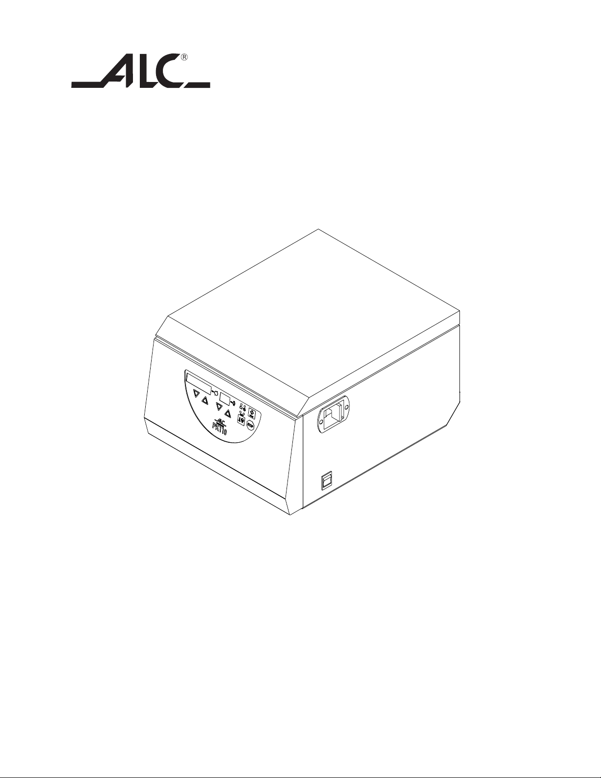
Instruction / Service Manual
ALC Centrifuge
Model PK110
Manual P/N 36100139
Rev. F Dated 26FEB08
Page 2

NOTICE
THE MATERIAL IN THIS MANUAL IS FOR INFORMATION PURPOSES ONLY. THE CONTENTS
AND THE PRODUCT IT DESCRIBES ARE SUBJECT TO CHANGE WITHOUT NOTICE. ALC
MAKES NO REPRESENTATIONS OR WARRANTIES WITH RESPECT TO THIS MANUAL. IN NO
EVENT SHALL ALC BE LIABLE FOR ANY DAMAGES, DIRECT OR INCIDENTAL, ARISING OUT
OF OR RELATED TO THE USE OF THIS MANUAL.
For repair information or replacement parts assistance from the manufacturer,
call Customer Service using our toll free telephone number.
800-
(FAX)
522-7746
828-658-2576
ii
Page 3

REVISION STATUS
INDEX DATE
F 02/08 Service Pages 25-28 Spare Parts Codes Update
AMENDED PAGES NOTES
Create JGC version from ALC’sC
Add service sectionD 08/00
Service page 27
Additional spare parts for lockE 06/03
iii
Page 4

Contents
1. MANUFACTURER ..................................................................................................................... 1
1.1 User manual ................................................................................................................... 1
1.2 Explanation of symbols ................................................................................................... 1
1.3 Safety precautions .......................................................................................................... 1
1.4 Safety Devices and Notices ............................................................................................ 2
2. INSTALLATION ........................................................................................................................ 2
2.1 Transport, Packaging, Lifting ........................................................................................... 2
2.2 Installation ...................................................................................................................... 2
2.3 Power Source Wiring ...................................................................................................... 3
2.4 Environmental Conditions ................................................................................................ 3
2.5 Lid Unlock ...................................................................................................................... 3
2.6 Emergency Lid Unlock .................................................................................................... 3
2.7 Inspection ....................................................................................................................... 4
2.8 Fitting the Rotor to the Drive Shaft .................................................................................. 4
2.9 Removal of the Rotor....................................................................................................... 4
3. SPECIFICATIONS .................................................................................................................... 5
3.1 Dimensions and Weight .................................................................................................. 5
3.2 Centrifugation Characteristics ......................................................................................... 5
3.3 Electrical Characteristics ................................................................................................ 5
3.4. Specifications ................................................................................................................. 5
4. DESCRIPTION AND PERFORMANCE ..................................................................................... 6
4.1 Functional Principles ...................................................................................................... 6
4.1.1 Drive System ................................................................................................... 6
4.1.2 Lid Interlock Safety System ............................................................................. 6
4.1.3 Imbalance Sensor ............................................................................................ 6
4.2 Rotors - Performance ...................................................................................................... 7
4.2.1 Rotors - Table .................................................................................................. 7
4.2.2 Performance .................................................................................................... 7
4.3 RCF Calculation .............................................................................................................. 8
4.4 Processing and Control Interface .................................................................................... 10
5. OPERATION PROCEDURE ...................................................................................................... 11
5.0 Instructions for the Operator............................................................................................ 11
5.1 Power Switch - Cover Unlock .......................................................................................... 11
5.2 Loading Balance ............................................................................................................. 11
5.3 Setting Centrifugation Parameters................................................................................... 12
5.3.1 Acceleration and braking ................................................................................. 12
5.3.2 Setting Speed and Time Values ...................................................................... 12
5.4 Starting the Centrifuge .................................................................................................... 12
5.5 Stopping the Centrifuge ................................................................................................... 13
5.6 Messages - Alarms ............................................................................................. 13
iv
Page 5

6. HAZARDS, PRECAUTIONS AND USE LIMITATIONS .............................................................. 14
6.1 Dangerous operations - work conditions to avoid ............................................................. 14
6.2 EN 61010-2-020 STANDARD .......................................................................................... 14
6.3 Rotor and Accessory Precautions................................................................................... 15
6.3.1 Corrosion Information ....................................................................................... 15
6.3.2 Contamination Hazards ................................................................................... 16
7. ROUTINE MAINTENANCE ........................................................................................................ 17
7.1 Rotating Equipment and Centrifugation Chamber Cleaning .............................................. 17
7.2 Exterior Cleaning ............................................................................................................ 18
7.3 Fuses ........................................................................................................................ 18
8. OPERATOR’S NOTES.............................................................................................................. 19
9. CERTIFICATE of DECONTAMINATION and CLEANING .......................................................... 20
10. WARRANTY ........................................................................................................................ 21
SERVICE SECTION, PART II
v
Page 6

1. MANUFACTURER
1.3 Safety precautions
For more information about the ALC PK110
centrifuge, please contact:
ALC
170 Marcel Drive
Winchester, VA 22602
Telephone (540) 869-5904
Toll Free (800) 556-2323
Fax (540) 869-0693
1.1 User Manual
This manual is part of the centrifuge and it
should be saved for future notes and
consultations. Always store the manual close
to the appliance and in a safe place, so that
it is always readily available.
ALC recommends that all users read this
manual.
1.2 Explanation of symbols
The following symbols are used on the PK110
centrifuge.
• This centrifuge was properly manufactured
and is safe and reliable. It could however
become dangerous for the operator or for
other people if:
• it is used by incompetent personnel or
not according to the attached instructions
• it is used for purposes other than the
ones for which it was designed
• it is incorrectly grounded
• Normal use of the centrifuge could require
the handling hazardous samples. All users
and maintenance personnel should be
trained in the proper handling of these
samples.
• The centrifuge cannot be electrically and/
or mechanically connected to other
instruments.
• This centrifuge is not explosion-proof.
• Maximum density of the centrifugation
3
samples should not exceed 1200 kg/m
.
Located on the main switch, this symbol
indicates that the main power is ON.
I
Located on the main switch, this symbol
indicates that the ce n t rifuge is
O
disconnected from the main power
supply.
This symbol indicates important safety
information. Failure to follow the
instructions marked with this symbol
could result in damage to the centrifuge
and/or the operator.
This symbol indicates the presence of
high voltage. Only authorized service
personnel can interact with
components in the areas marked with
this symbol. Failure to respect this
symbol could result in serious injury or
death.
• Use only ALC rotating equipment with this
centrifuge.
• Only original ALC spare parts can be used.
• No unauthorized personnel may alter this
equipment in any way.
• Do not use the centrifuge when it is
damaged or operating irregularly. Notify the
manufacturer as soon as possible about any
problems.
1
Page 7

1.4 Safety Devices and Notices
2. INSTALLATION
To ensure operator safety the centrifuge has the
following electrical and mechanical
characteristics :
• The centrifuge will not start unless the lid is
locked.
• The lid cannot be opened during
centrifugation.
• The centrifuge has electronic self-diagnosis
capability; any possible electrical system
malfunctions are displayed digitally. At the
same time, the centrifuge is disabled to
prevent unsafe operation of the machine.
• The centri f u ge is equipped w i t h an
automatic load imbalance safety device.
• The case of the centrifuge is armored, and
the reinforced bowl is made of AISI 304
stainless steel.
• The lid is supported by a strong, dependable
gas spring that holds the lid open until the
operator actively closes it.
2.1 Transport, Packaging, Lifting
The centrifuge is shipped in special packaging
to protect it from possible harm.
Due to the weight of the machine, proper
handling equipment (e.g.: pallet jack or fork lift)
must be used. The handling equipment should
comply with current regulations, and should only
be used by properly trained individuals.
1. The centrifuge should be stored and
transported under the following conditions:
a) Ambient temperature -20°C to +50°C.
b) Relative humidity up to 90% and not
exceeding the dew point.
2. After the centrifuge is unpacked, the
contents of the package should be carefully
compared to the items on the packing list.
3. Retain the packaging until the centrifuge
has been tested.
2.2 Installation
• The electrical main has a bipolar switch.
• Ground connection resistance, applied
voltage and leakage current are tested and
certified.
• The centrifuge is equipped with identification
plates and operating instructions.
The machine should be installed in a room
free of dust and moisture. Place the centrifuge
on a bench top rigid and strong enough to
comfortably support its weight.
IMPORTANT:
AT LEAST 2 PEOPLE ARE REQUIRED TO
LIFT THE CENTRIFUGE FROM THE PALLET
AND PLACE IT ON THE BENCH.
WARNING:
LEAVE 12 INCHES OF FREE SPACE ON
EACH SIDE OF AND BEHIND THE
MACHINE TO FACI LITATE PROPER
VENTILATION.
2
Page 8
2.3 Power Source Wiring
Check main lines and frequency:
They must correspond to the
values shown on the instrument
identification label.
PK110 230V:
230 V ± 10% 50/60 Hz (1 phase + ground)
2. Check the lid indicator on the display
panel. The light should be on indicating
that the rotor is stationary and that the lid
can be opened.
3. Pull the lever on the top right side of the
machine to open the lid.
WARNING:
PK110 120V:
120 V ± 10% 60 Hz (1 phase + ground)
WARNING:
ENSURE THAT THE POWER SOURCE IS
PROPERLY GROUNDED.
The centrifuge is equipped with R.F.I. filters.
The manufacturer declines all responsibility
for any damages due to improper grounding
of the machine.
2.4 Environmental conditions
- Indoor use.
- Temperature: 5°C to + 40°C.
- Maximum relati v e humidity: 80% fo r
temperatures up to 31°C decreasing linearly
to 50% relative humidity at 40°C.
2.5 Lid Unlock
1. Turn the centrifuge on (switch is on the left
side of the unit).
BEFORE PR OCEEDING TO THE
INSTALLATION O PERATION, IT IS
IMPORTANT TO TURN THE CENTRIFUGE
OFF.
4. After opening the lid, remove any possible
packaging around the spindle. Unscrew the
rotor nut from the top of the spindle. Carefully
clean the inside of the centrifugation chamber
removing any packaging residue. Because of
the turbulence caused by centrifugation, solid
particles accidentally left in the chamber could
create excessive wear of the bowl and rotor.
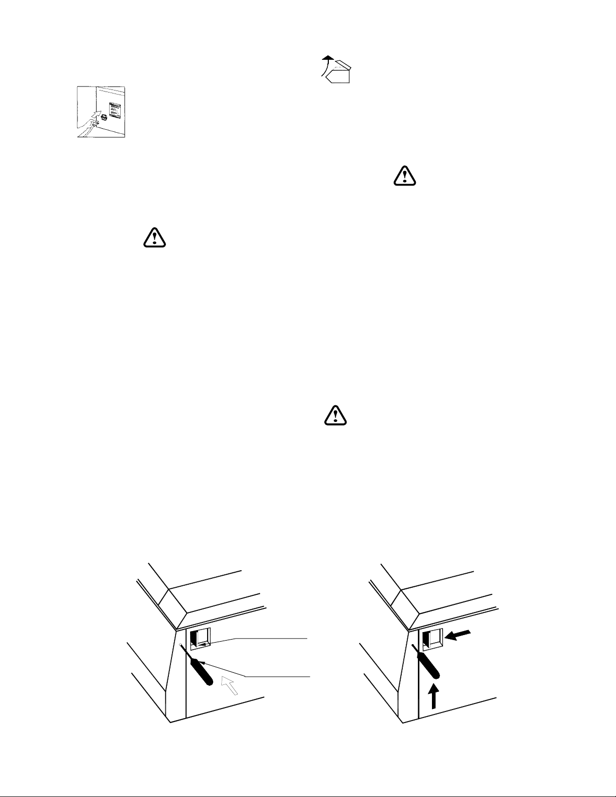
2.6 Emergency Lid Unlock
In the event of power failure, the lid can
be opened using the special tools
supplied with the centrifuge. The centrifuge
must be unplugged before starting this
procedure.
1. Remove the nylon screw in the hole on the
right side of the centrifuge as identified below.
2. Insert the unlocking tool, keeping the tool
horizontal (
figure a
).
Latch Lever
Unlocking Tool
figure a figure b
3
Page 9
3. Lift the unlocking tool then, while lifting the
tool, pull the lid handle forward (
4. After the lid is open, replace the nylon screw.
figure b
).
WARNING:
SHOULD THE POWER FAIL DURING
CENTRIFUGATION, WAIT AT LEAST 5
MINUTES FOR THE ROTOR TO STOP
TURNING. OPEN THE LID CAUTIOUSLY
AND OBSERVE THE ROTOR; IF IT IS STILL
ROTATING, CLOSE THE LID AND WAIT AN
ADDITIONAL 5 MINUTES BEFORE
REPEATING THE OPERATION.
2.7 Inspection
Before installation, the rotating
equipment should be thoroughly inspected for
corrosion and dirt (see 6.3). The rotor and
spindle should be clean and undamaged.
These accessories should be wiped clean
before each use.
Any failure to follow the above advice may
have serious consequences for the safety of
the appliance. Corrosion can lead to stress
fatigue, which will eventually weaken the rotor
and may lead to disruption and severe
damage to the centrifuge. If visible signs of
corrosion or anomalies in the rotor or buckets
are p resent, do not use t he a ffected
accessories. Contact an authorized service
provider for assistance.
2.8 Fitting the Rotor to the Drive Shaft
The rotor’s drive is made by means of
a pin inserted in the motor’s shaft,
which must coincide with a slot in the
rotor.
To ensure proper mounting, always do the
following:
• ensure that both the spindle of the motor and
the hole of the rotor are clean;
• place the rotor in the centrifuge bowl and
slip it onto the motor shaft.
• align the slot in the collar with the pin on the
spindle;
• install and strongly tighten (with the supplied
wrench) the hexagonal nut on the threaded
shaft of the motor .
WARNING:
BE SURE THAT THE ROTOR IS LOCKED
BEFORE STARTING THE CENTRIFUGE.
2.9 Removal of the Rotor
To remove the rotor from the motor shaft : Using
the wrench supplied, loosen the shaft nut.
Remove the nut and lift the rotor with both hands.
4
Page 10

3. SPECIFICATIONS
3.1 Dimensions and weight
Height x Width x Depth: .......................... 11 x 14.6 x 18.1 in (28 x 37 x 46 cm)
Net Weight: ............................................ 61.7 lbs. (28 kg)
3.2 Centrifugation specifications
Max. allowable capacity: ........................ with swing-out rotor 4 x 135 ml
with fixed-angle rotor 6 x 50 ml
Max. Allowable density: ......................... 1200 Kg/ m
Max. allowable weight:........................... 0.648 Kg
Max. speed: ........................................... with swing-out rotor 4000 rpm
Max. RCF at tip:..................................... with swing-out rotor 2647 x g
Max. temperature: .................................. T
Max. noise: ............................................. < 57 dBA
3.3 Electrical specifications
Nominal operating voltage: .................... 230V ± 10% 50/60 Hz
Current................................................... 1.5A (@ 230V)
Max power (steady state): ..................... 150 W
3
with fixed-angle rotor 6300 rpm
with fixed-angle rotor 3661 x g
ambient
+ 15°C
120V ± 10% 60 Hz
2.5A (@ 120V)
3.4. Features
• Microprocessor controlled
• Set/reading speed 300 - 6300 rpm (in steps of 10 rpm); accuracy: ± 20 rpm
• Fast or slow acceleration
• Fast or slow deceleration
• Timer can be set for: 1 min. up to 99 min. + hold
• Electronic imbalance detector
• Direct drive
• Brushless induction motor
5
Page 11

4. DESCRIPTION AND
PERFORMANCE
4.1 Functional principles
The ALC PK110 centrifuge is designed for
laboratory use. It will separate the components
of fluids into layers of varying density by
subjecting them to high forces. Swing out rotors
can carry a greater load than fixed angle rotors.
The larger the diameter of a rotor, with
accessories, the greater its load capacity and
the lower its maximum speed. Relative
Centrifugal Force (RCF) generated by a rotor
is directly proportional to its useful
sedimentation radius and to the value of its
speed squared.
4.1.1 Drive system
A three phase asynchronous motor drives the
rotating equipment. The rotor is contained in
a sealed, armor plated centrifugation chamber.
4.1.2 Lid interlock safety system
The centrifuge is equipped with an interlock
system that prevents opening of the centrifuge
lid when the rotor is spinning. The centrifuge
will not operate until the lid is closed and
latched in place. The lid remains latched until
the rotor stops spinning. NOTE: If a power
failure occurs, access to the samples in the
centrifuge is possible. This procedure requires
the use of a special tool. Follow the emergency
lid unlock procedure found in Section 2.6.
4.1.3 Imbalance Sensor
The centrifuge is equipped with a load
imbalance detector. In case of excessive
imbalance the machine stops automatically.
The display reads “INBL” – this message will
disappear once the lid has been opened to
balance the load (see Section 5.6). Imbalance
tolerance depends upon the rotor in use.
Carefully balance the sample load to avoid
actuating the imbalance detection system.
6
Page 12

4.2 Rotors - Performance
4.2.1 Rotors - Table
foepyT
tnempiuqE
#golataC yticapaC
1/62G-O 41001211 lm531X4 º09-º0 *92001211 58001211 841
2/62G-O 51000211 lm51X61 º09-º0 --- 58001211 441
3/62G-O 61000211 lm51X8 °09-º0 42730211 58001211 441
4/62G-O 71000211 lm51X8 °09-º0 ---- 58001211 441
1G-F 81000211
3G-F 91000211 lm51X42 º54 ---- ---- 331
21G-A 02000211 lm5.1/0.2x02 º54 **97427111 ---- 87
* tseuqerno
delaeston**
lacinoc
For all swing-out rotors,(prefix OG-26/ ), a
Cytokit accessory (Cat. no. 11210085) is
available. Each Cytokit contains the following:
• 2 cytobucket holders for OG-26 rotors
• 2 cytobuckets
• 50 slides with foam pad
• 1 silicon tube
• 1 silicon pad
• 1 user manual for cytobuckets
noitisopmocdaoL seirosseccA
a
lm05x6
º04 ---- ---- 131
pacgnilaeS
#golatac
tikotyC
#golatac
lufesU
xam
suidar
)mm(
4.2.2 Performance
foepyT
tnempiuqe
1/62G-O 0004 7462 5.6 65
2/62G-O 0004 5752 01 75
3/62G-O 0004 5752 9 65
4/62G-O 0004 5752 8 65
1G-F 0005 1663 01 75
3G-F 0004 9732 01 55
21G-A 0036 1643 5.5 05
deeps.xaM
)mpr(
FCRxaM
)gx(
TD
)C°(
7
esioN
)ABd(
Page 13
4.3 RCF Calculation
radius
xg
RPM
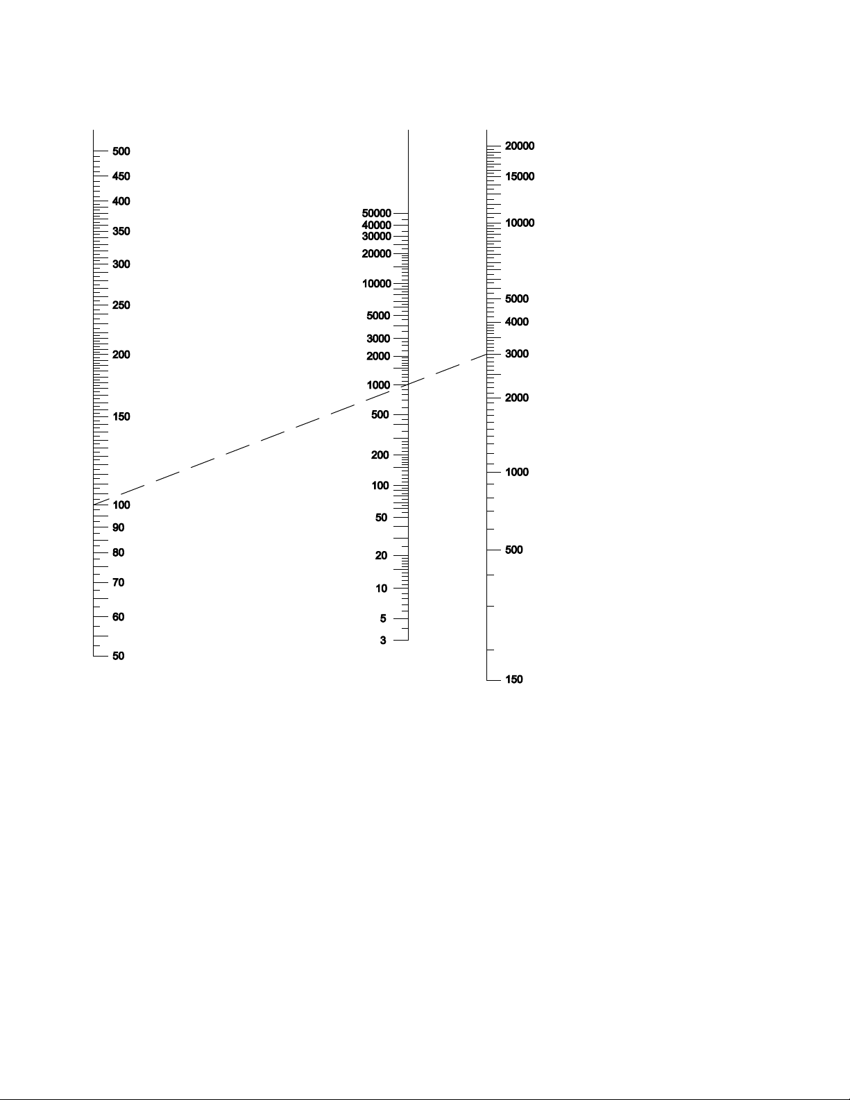
Total separating force applied to a sample in
a centrifuge depends on the duration of the
centrifuge run and on the RCF (relative
centrifuge force) applied to the sample. RCF
is generally calculated in units x gravity (x g).
The diagram above allows you to graphically
calculate RCF by drawing a line from the
centrifugal radius (on left) to the speed (on
right). The value of the RCF (xg) applied to
the sample is approximated by the value at
the point where the line crosses the “xg” axis
(center).
8
Page 14

Centrifugal radius is defined as the distance
from the axis of rotation to the point on the
sample at which you wish to measure the RCF.
This point is generally the tip of the sample
farthest from the axis of rotation. By popular
convention, this distance is measured in units
of millimeters.
EXAMPLE
To find the RCF value (xg) applied to a sample
in a rotor/bucket/accessory system with a
centrifugal radius of 100 mm (0.1m) and
rotating at 3000 RPM, place a ruler on the
scale joining the point marked 100 on the left
with the point marked 3000 on the right. At
the point where the line crosses the center
scale (xg), the corresponding value is
approximately 1,000. In this example, the
outer tip of the sample is subjected to RCF =
1,000 x g
The following funct i o ns represen t the
mathematical relationship between RCF (xg),
centrifugal radius (r) and speed (rpm). When
the ac c u racy of th e graphical method
described above is not satisfactory, these
functions can be used to obtain more accurate
results.
RCF (units x g) = 1.118 · 10-6· n2· r where n = RPM
n =
rcf
1,118 * 10
-6
r
*
r = radius in millimeters
9
Page 15
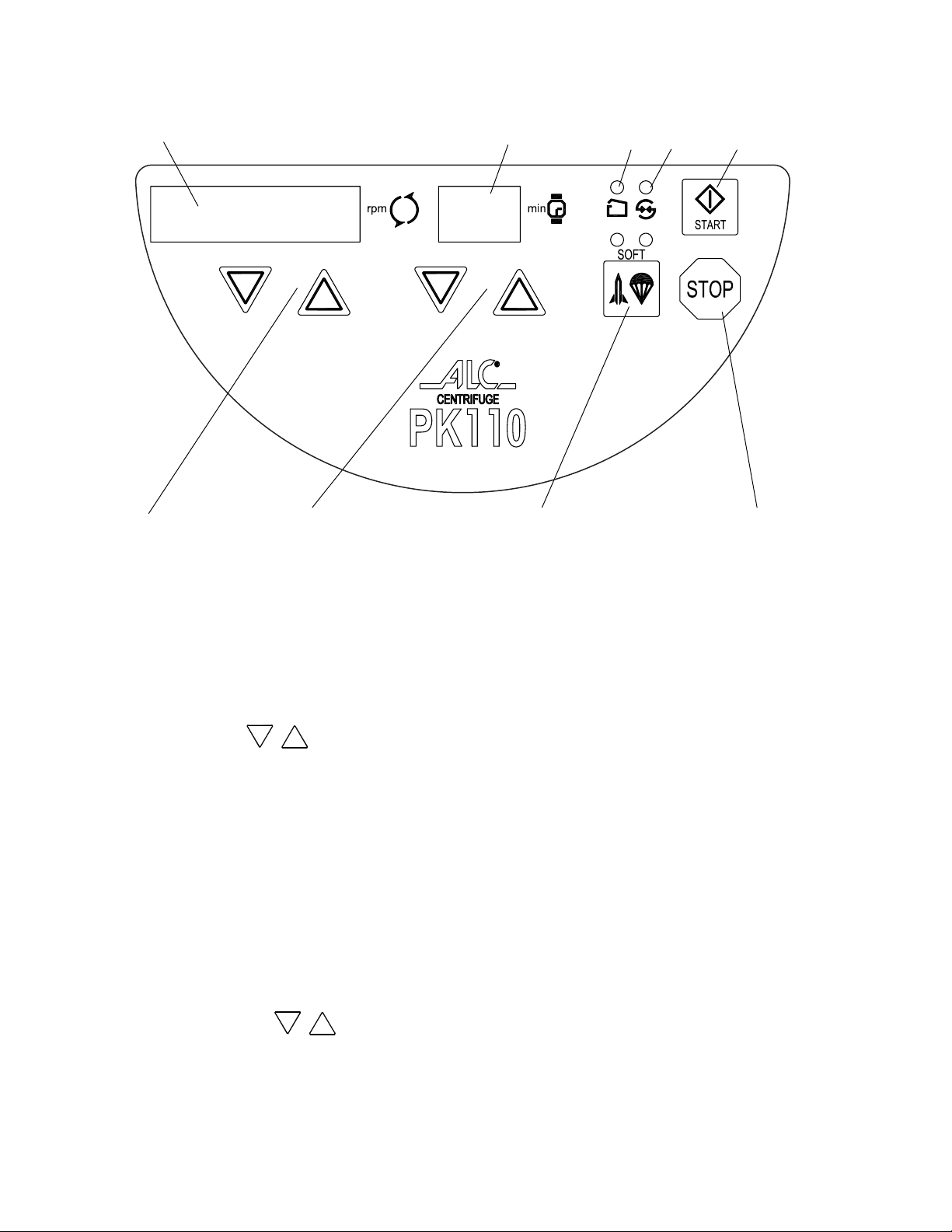
4.4 Processing & control interface
1
2
4 7 5
1. Speed display (units of rpm) When the
machine is stopped, this field displays the
set speed. When the machine is running and
the numbers are constant, this field displays
actual speed. When the machine is running
and the numbers are flashing, this field
displays set speed.
2. SET rpm keys : These keys are
used for increasing or decreasing speed
settings.
3. Time display (units of minutes) When
the machine is stopped, this field displays
the set centrifugation time. When the
machine is running, the rema i n i ng
centrifugation time is displayed; when the
time is set a t “HOLD” (con t i nuous
operation), the display shows elapsed
time.
4. Set minutes keys : These keys
are used for increasing or decreasing time
settings.
5. STOP key Pressing this key stops the
centrifuge manually.
3
9 8 6
6. START key Pressing this key starts the
centrifugation cycle.
7. SOFT key This key is used to sequence
through the activation/de-activation of low
acceleration and low deceleration. When
both LED’s are off (high acceleration and
deceleration), the follwing functions will be
activated in sequence:
• Slow deceleration
• Slow acceleration
• Slow acceleration and deceleration
• High acceleration and deceleration
The corresponding LED will indicate
activated soft function status.
8. RUNNING LED: This indicator flashes
during the accelera t i o n an d the
deceleration phases. It is constant when
actual speed equals set speed.
9. LID OPENING LED: When this indicator is
illuminated the lid can be opened. It
illuminates when the rotor is stationary.
10
Page 16
5. OPERATION PROCEDURE
5.0 Instructions for the operator
1. As a precautionary measure, the operator
should remain with the centrifuge until it
reaches the set speed.
2. The operator should also return to the
centrifuge immediately upon completion of
the run.
5.1 Power Switch - Cover Unlock
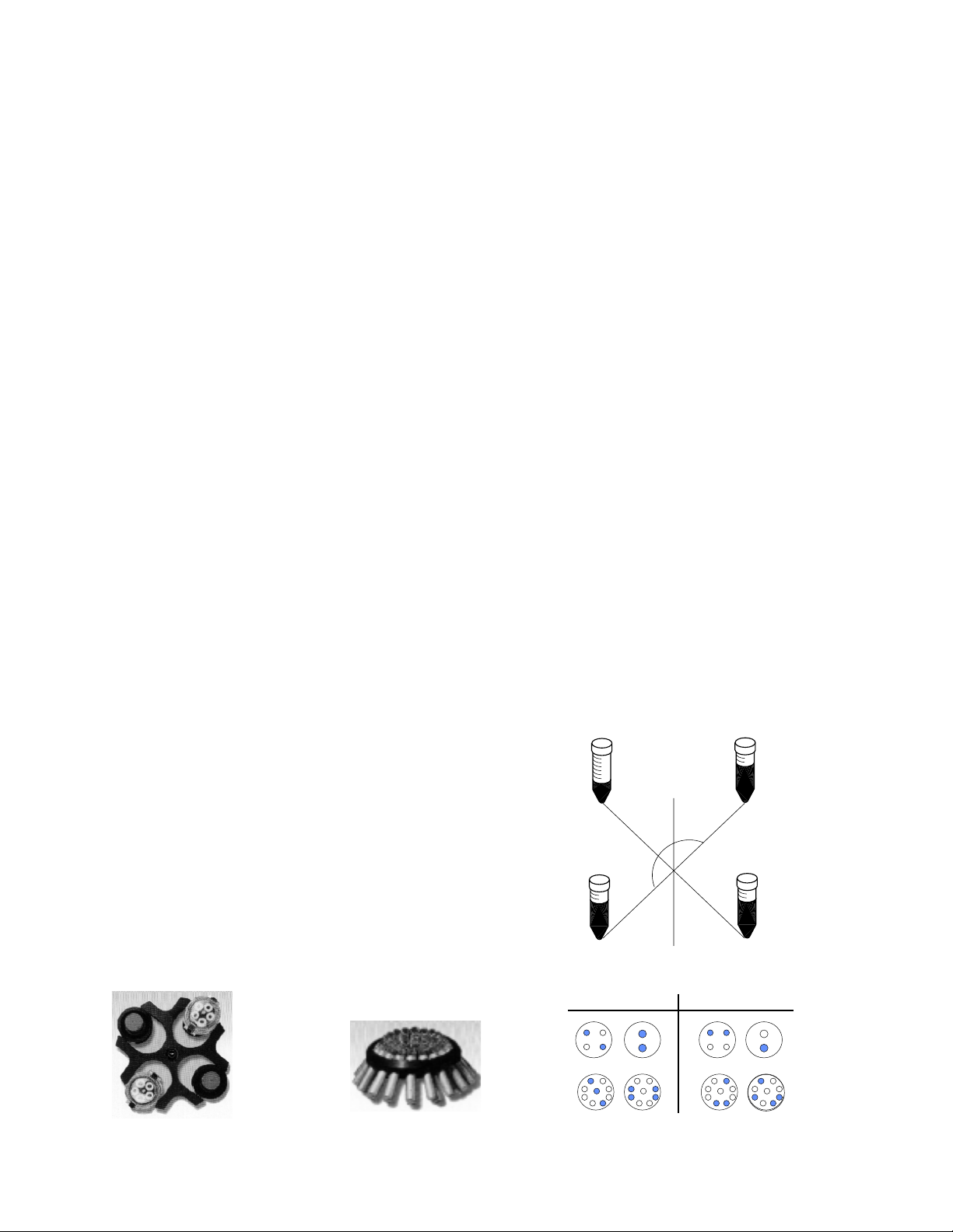
5.2.3 To correctly distribute the load, tubes and
adapters should be placed so that the load is
symmetrically distributed with respect to the axis
of rotation. (see fig. 3)
5.2.4 For partial loads of swing-out rotating
equipment, tubes should also be symmetrically
distributed with respect to the rotational axis of
the swinging bucket. (see fig. 4).
5.2.5 When liquids with densities higher than
1.2 gm/ml must be processed, the max. rpm
should be reduced according to the following
formula:
1. When the centrifuge is turned on (switch
is located on the left side of the centrifuge)
the centrifuge is connected to the main
circuit. The operating conditions will be the
same as in the last working cycle.
2. When the rotor is stationary and the LED
is on, it is possible to open the lid. The
mechanical latch on the upper right panel
of the centrifuge opens the lid when it is
pulled toward the front.
5.2 Loading balance
5.2.1 All rotating equipment is dynamically
balanced prior to shipment. For swinging
bucket rotors, reference numbers and marks
on the buckets correspond to matching marks
on the rotor. Buckets should be positioned on
the rotor so that the numbers on the buckets
correspond to the same numbers on the rotor
itself (eg. bucket #2 positioned in rotor position
#2, see fig. 1).
Allowed rpm = max. rpm * (1.2/New density)
5.2.6 When closing the lid, lower it pressing
on the front edges until the hook in the lid clicks
into the lid lock mechanism. The centrifuge will
only operate when the lid is completely closed
and locked.
NOTE: Tubes should be balanced
within ± 2 grams to facilitate the best possible
sample separation.
NO
180˚
5.2.2. For fixed angle rotors with carriers, all
carriers must be inserted into the rotor before
starting the run. This holds true even when partial
loads are being processed (see fig. 2).
1
1
2
2
figure 1 figure 2
11
YES
correct
figure 3
incorrect
figure 4
Page 17

5.3 Setting centrifugation Parameters
5.3.2. Setting speed and time values
INTRODUCTION: The control interface of the
PK110 is designed to make centrifuge
operation as simple as possible. All of the
buttons are dedicated to specific functions.
Because of this, centrifuge operators do not
need extensive training to understand the
system. This section is designed to educate
and prepare the user to use the PK110. The
following centrifugation parameters can be set
by the operator:
a) Speed in rpm
b) Centrifugation time
(300 rpm up to 6,300 rpm).
(1 min up to 99 min + hold)
c) Acceleration type
d) Deceleration type
5.3.1 Acceleration and Deceleration.
SOFT key
Located on the front panel, the
SOFT key is used to start a low
acceleration and a deceleration
by inertia.
Two dedicated LEDs, which can
be activated by se quence
pressing the SOFT key, will indicate set
acceleration and deceleration.
Fast acceleration (led off)
Soft acceleration (led on)
Fast deceleration (led off)
Soft deceleration (led on)
In the following diagram, different acceleration
and deceleration profiles have been shown,
as available by means of the SOFT key.
When you touch one of the
SET keys , the
corresponding display will start
to flash.
When the display flashes, it is
possible to change the selected parameter
using the SET keys.
SET speed 300 to 6300 rpm (see 4.2 for rotor
speed ratings).
SET time 1 to 99 min + hold
1 second after changes are complete, the
display stops flashing. This confirms the new
SET values.
5.4 Starting the centrifuge
BASIC CONDITION: Lid closed
1. Press “START” key.
The centrifuge will ac c e lerate
according to the selected
acceleration profile until the set
speed is reached. When the set time
has expired, deceleration will begin.
• Lid opening LED extinguishes
• The “running” LED flashes while the rotor
is accelerating and remains constantly
illuminated while the rotor is at set speed.
rpm
4000
2000
1000
0
O-G26/ F-G3
10
20 30
40
ACL soft
DCL soft
50
60 sec
57 dBA
40 dBA
12
rpm
5000
2000
1000
F-G1
ACL soft
DCL soft
20 30
10
0
40
60
50
70 sec
57 dBA
40 dBA
Page 18

• During the run time the speed display shows
actual values. The time display shows
remaining run time. If the time setting is
“HOLD”, the time display shows elapsed run
time.
5.6 Messages - Alarms
The microprocessor displays error messages
to indicate errors, malfunctions or breakdowns.
The messages are expressed with the
following codes.
NOTE:
if set speed is higher than the
maximum speed of the rotor, the “running” LED
will continue flashing (see 5.6 SET). In this
case, the program should be corrected as
soon as possible.
During the run time to read and change set
values, press one of the two SET keys:
• The display starts to flash and shows the set
values for 1 second.
- While the display is flashing it is possible to
change the set values.
- During a run, it is possible to change the
deceleration setting (high or “SOFT”).
5.5 Stopping the centrifuge
Once the pre-set time has elapsed, the
centrifuge automatically stops the rotor
at a rate determined by the deceleration
setting.
Pressing the STOP key at any time
will cause the centrifuge to stop the rotor. NOTE:
Automatic braking will occur under conditions
of load imbalance.
LINE Appears when the mains voltage is out
of tolerance (see section 2.3).
End Appears at the end of every
centrifugation cycle after the rotor comes
to a stop. The message disappears when
the lid is opened or when any key is
pressed.
Lid Appears when the START key is
pressed and the lid is not locked. The “LID”
message is accompanied by an audible
signal. This message will disappear when
the lid is locked.
INBL Appears when the load is unbalanced.
The message is accompanied by an
audible signal. The centrifuge stops to
allow the user to rebalance the load (5.2).
The message disappears when the lid is
opened.
E4 Appears when a power failure occurs.
The message is accompanied by an
audible signal. The centrifuge decelerates
and the system shuts down. When power
is restored, the message reappears. It
remains on the display until the next
operation is started.
An audible intermittent alarm Appears when
set speed is higher than the maximum rated
speed of the rotor. The message disappears
when the centrifuge is stopped or when the
parameter is corrected.
E... Messages ‘E...’ (e.g. E01) together with
an audible alarm indicate failure conditions.
In these cases contact your authorized
technical service center.
13
Page 19

6. HAZARDS, PRECAUTIONS AND USE
LIMITATIONS
• Spinning samples of densities higher than
allowed for the given speed.
6.1Dangerous operations - work
conditions to avoid:
• Using the centrifuge if it has not been
properly installed.
• Attaching the rotor to the drive shaft
incorrectly or placing the buckets on the
rotor incorrectly.
• Leaning on the centrifuge during operation.
• Moving or shifting the machine during
centrifugation.
• Using the centrifuge with rotors and/or
buckets showing corrosion, wear marks
and/or cracking.
• Using the centrifuge with rotors and/or
accessories not approved by the
manufacturer.
• Usi n g the centrifuge in e x plosive
environments or with explosive samples or
chemical materials subject to violent
reaction.
• Alteration of and/or tampering with the
electronic and mechanical parts of the
centrifuge.
6.2 EN 61010-2-020 STANDARD
The En 61010-2-020 standard relative to
laboratory centrifuges recommends that the
user:
• Mark out a clearance envelope 300 mm
(12 in.) around the centrifuge or establish
special procedures for the non entry of all
persons or all dangerous materials into this
space during the operation of the
centrifuge.
• Pro v i d e an emerge n c y stop switc h
enabling the main power source to be cut
in the case of malfunction. The switch
should be placed at a safe distance from
the centrifuge, preferably in a different
room from that in which the centrifuge is
situated.
• Running an Unbalanced load which
causes excessive v i bration of the
centrifuge.
• Running a rotor without its full complement
of buckets or carriers, even for partial
loads.
• Exceeding the maximum speed indicated
in the “max. rp m ” col u m n o f th e
performance table (see 4.2.2).
• Using old accessories on a new machine.
• Using tubes and/or bottles not suited for
centrifugation.
14
Page 20

6.3 Rotor and accessory precautions
6.3.1 Corrosion information
ALC rotors are made of aluminium alloy and
are designed to operate at their rated RCF for
many years. With careful use they will resist
corrosion, lowering the possibility of excessive
imbalance, disruption and subsequent damage
to the instrument. The primary conditions for the
initiation of corrosion exist in every laboratory
during daily use of the centrifuge. For this reason
it is essential that due care and attention be paid
to inspection and cleaning.
CHEMICAL CORROSION
This corrosion is characterized by chemical
reactions due to the existence of any electrolytic
liquid on the surface of the equipment. If these
substances are allowed to remain on the
surface corrosion will almost certainly occur.
The first sign of this type of corrosion is a
discoloration or pitting of the anodized surface.
Acidic and alkaline solutions sustaining their
pH level will also create corrosion of aluminium
equipment. Chlorides, which are present in
salts (human skin secretions are a common
source!), are among the most aggressive and
harmful substances commonly found in the
laboratory.
Chemical products that cause corrosion do not
necessarily originate from broken tubes. For
example, they could come from:
•· Chemical vapors present in the laboratory
which condense on the centrifuge and its
accessories.
• Corrosive liquids originating from overfilled
uncapped tubes (the liquid overflows
during centrifugation)
• Inserts, adapters, racks and bottles with
exteriors soiled by a chemical product or
poorly rinsed after decontamination (with
bleach, for example).
NOTE: If the products are very corrosive, simple
rinsing is insufficient. Residual traces dissolve
little by little with the humidity present in the
bottom of the rotor pocket.
BEWARE of the presence of solid particles
beneath tubes, inserts, racks or adapters.
These particles are crushed by the centrifugal
force and penetrate the protective, anodized
layer of buckets and rotors, thus creating
pathways for corrosion.
STRESS CORROSION
This term relates to the phenomenon of
accelerated corrosion due to the effect of
centrifugal force when a corrosive chemical is
in contact with the alloy. From the time when the
aluminium alloy has been attacked by
chemicals, stress corrosion begins to appear.
As it occurs on a microscopic scale it is even
more dangerous than macroscopic corrosion
since it is invisible to the naked eye.
During centrifugation chemicals responsible
for corrosion are also subjected to very high
forces, which push them against the alloy. This
close contact facilitates the chemical reaction
which occurs much faster than it does in a
static situation. Moreover, centrifugal force is
directional. Because of this, corrosion under
stress creates, with a very small amount of
corrosive product, straight microscopic
fissures. Each centrifugation run allows the
chemical to migrate further and further.
Fissures or cracks, although microscopic, are
a flaw in the metal, breaking the cohesion of
the material. As one weak link in a chain allows
the chain to break, so the microfissures break
the chain of resistance of the accessory to
centrifugal force. Because accessories are
designed with high safety factors, rupture does
not occur as soon as the first microfissures
are produced.
Depending on the location of the fissure,
disruption may occur before it reaches the
external surface of the accessory. The fissure
create s a weakness, which makes the
15
Page 21
accessory less and less resistant to mechanical
fatigue. The corrosion caused by a small
amount of corrosive product does not disrupt
the accessory but makes it mechanically weaker
and weaker until disruption occurs due to both
centrifugal force and fatigue.
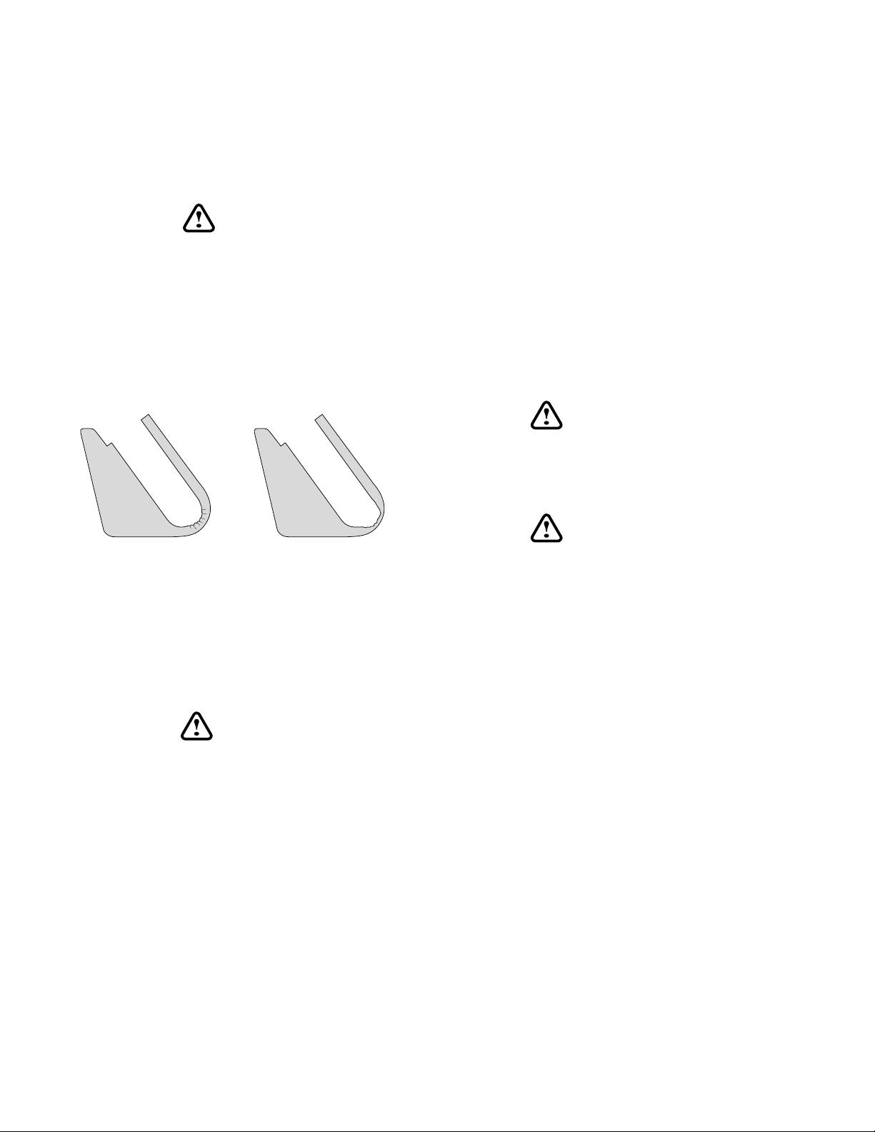
WARNING:
BECAUSE STRESS CORROSION IS
LARGELY INVISIBLE, IT IS ESSENTIAL THAT
ROTATING EQUIPMENT BE SCRUTINISED
REGULARLY PAYING PARTICULAR
ATTENTION TO SUSCEPTIBLE PARTS
SUCH AS THE BOTTOM OF POCKETS, THE
OUTER EDGES AND THE BASE OF THE
ROTATING EQUIPMENT.
of warming (eg. autoclave) the rotating
equipment should always be completely
disassembled before being subjected to heat.
They should also be completely disassembled
prior to external chemical cleaning. Seals,
tubes and plastic components should be
decontaminated with the method most suitable
for them, which might not be the same as for
the rotating equipment.
Note that the black color on the surface of the
rotating equipment will be gradually washed
out if the rotor is regularly autoclaved or
bleached. This does not necessarily denote
degradation of the anodized surface.
WARNING:
ANY PART WHICH HAS BEEN SUBJECTED
TO TEMPERATURES ABOVE 130°C MUST
BE DISCARDED.
STRESS CORROSION
6.3.2 Contamination hazards
ALC centrifuges are likely to be used in
laboratories where hazardous substances are
frequently present.
CHEMICAL CORROSION
WARNING:
THE USER HAS THE RESPONSIBILITY
FOR CA R RYING OUT APPROPRIATE
DECONTAMINATION PROCEDURES.
USERS SHOULD BE AWARE OF THE
INTERNATIONALLY RECOGNIZED “
RATORY BIOSAFETY MANUAL
GIVES INFORMATION ON DECONTAMINATES, THEIR USE, DILUTIONS, PROPERT IES AN D POTE NTI AL APP LIC A TIONS.
IF HAZARDOUS MATERIAL IS SPILLED ON
OR INSIDE THE APPLIANCE, CLEAN THE
APPLIANCE AND ITS DRAIN HOSE USING
APPROPRIATE METHODS.
If decontamination procedures require the use
LABO-
”, WHICH
WARNING:
IF YOU HAVE A DOUBT AB OUT A
PARTI CULAR CLEANING METHO D ,
PLEASE CONTACT ALC TO VERIFY THAT
THE PROPOSED METHOD DOES NOT
DAMAGE THE APPLIANCE.
ALC makes no claims as to the effectiveness
of proprietary brands of decontaminating
solutions.
16
Page 22
7. ROUTINE MAINTENANCE
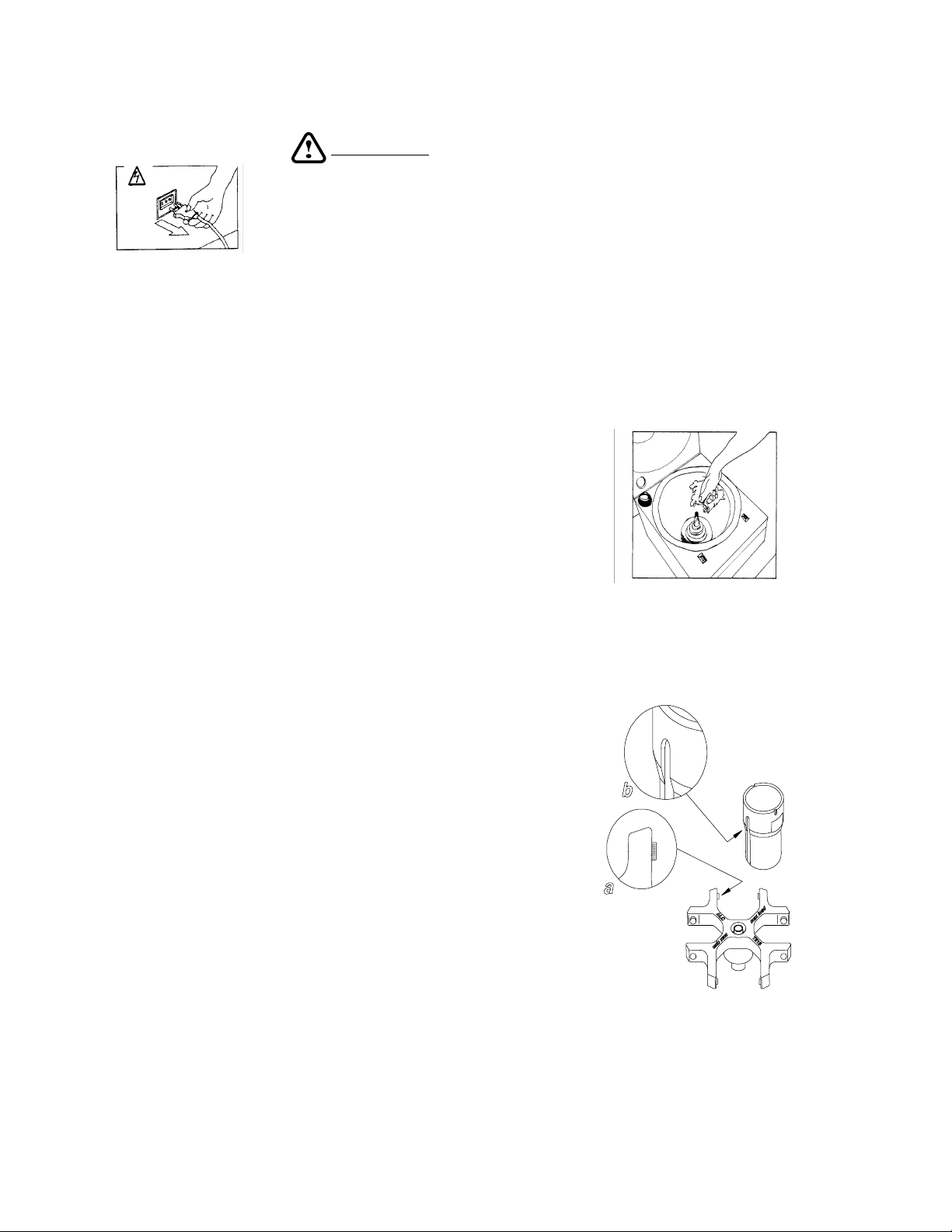
CAUTION:
During maintenance
operations,
disconnect the centrifuge
from t h e main po w e r
source (fig. 7.1).
fig. 7.1
7.1 Rotating Equipment and
Centrifugation Chamber Cleaning
Regular cleaning of rotors and of the
centrifugation chamber is vital to maintain
good working conditions. The operator must
wear proper protective equipment during the
cleaning (mask, gloves, etc.). It is also
important to verify the integrity of biosafety
components when they are used. The user
should always inspect the condition of seals
and lids prior to using them. Do not clean
them with materials that damage silicone and
polycarbonate. Ideally, rotors should be
washed after every run (at least weekly) in
warm water containing a few drops of mild
(not alkaline) detergent (domestic liquid soap
is ideal). ROTORS MUST BE WASHED
EVERY TIME SPILLAGE OCCURS. Do not
forget to wash the core of the rotating head
that comes into contact with the drive spindle.
Each rotor pocket (and bucket for swing-out
rotors) must be washed thoroughly using a
small nylon brush. Once the rotor has been
removed, it is easy to clean the centrifugation
chamber and gaskets. Use warm water with
non- alkaline detergent. Do not use corrosive
solvents. Once the rotor is clean, rinse it with
running water, preferably distilled. Dry the
rotor with a soft absorbent non-woven cloth
or tissue. The equipment can be dried with a
cloth or with a blow dryer. DO NOT USE
METAL WIRE BRUSHES and MAKE
CERTAIN THAT ROTOR SLOTS AND
BUCKETS ARE WELL-DRIED (fig. 7.2).
NEVER LEAVE damp rotors on a metal
surface (particularly stainless steel) because an
ALWAYS
electrochemical reaction could take place with
the aluminium or magnesium in the rotor. For
swing-out rotors, be sure to clean the dirty
grease from the studs and replace it with a small
amount of fresh grease. This will ensure that the
buckets swing freely. The majority of imbalance
problems arise from the failure of the user to
clean and grease the studs. Never apply
grease if studs and balancing slots have
not been carefully cleaned (fig. 7.3 a/b). Use
only the same kind of greases furnished in
the rotor packaging.
fig. 7.2
fig. 7.3
17
Page 23

7.2 Exterior cleaning
For correct cleaning, a light domestic-use
detergent is recommended. A mixture of 50%
isopropyl alcohol and water is also suggested
because it will not damage the labels.
7.3 Fuses
There are two fuses in the power supply line.
They are located in the power receptacle
under the line cord. (see fig. 7.4)
Fuse Specifications:
230V(50-60HZ) 5 x 20 mm TA2/250V
120V (60HZ) 5 x 20 mm TA4/120V
WARNING:
BEFORE PROCEEDING TO CHANGE THE
FUSES, DISCONNECT THE CENTRIFUGE
FROM THE MAIN POWER SOURCE.
Do not attempt to replace blown fuses until a
service engineer has determined the cause
of the failure.
fig. 7.4
18
Page 24

8. OPERATOR’S NOTES
etad
19
Page 25

9. CERTIFICATE of DECONTAMINATION and CLEANING
(For your convenience, use a copy of this page)
Read the instructions below carefully before sending an instrument, or parts of it, to
ALC Technical Service.
MR / MRS (NAME) ______________________________________________________
ESTABLISHMENT ______________________________________________________
DEPARTMENT _________________________________________________________
ADDRESS ________________________________ POST / ZIP CODE ____________
CITY _____________________ STATE / COUNTRY _________________________
CERTIFIES the cleaning and decontamination of the following:
CENTRIFUGE _____________________________ SERIAL N° __________________
ROTOR __________________________________ SERIAL N° __________________
ROTOR __________________________________ SERIAL N° __________________
ACCESSORY - Description ___________________ SERIAL N° __________________
ACCESSORY - Description ___________________ SERIAL N° __________________
NATURE of contamination
_____________________________________________________________________
_____________________________________________________________________
Decontamination PROCEDURE USED
_____________________________________________________________________
_____________________________________________________________________
Decontamination CERTIFIED by:
Mr / Mrs. __________________ Institution: _________________________________
Date _____________________ Signature: _________________________________
When an instrument, or parts of it, comes back after demonstration and requires servicing by Technical Service
personnel, the following procedure must be followed to ensure safety:
n Clean the instrument and decontaminate it.
n Complete this
n Attach this
Decontamination Certificate
Certificate
to the instrument (or accessory) before sending it to ALC.
with all the information required.
Technical Service personnel will not accept instruments without this
20
Decontamination Certificate
.
Page 26

Warranty
ALC warrants its products against defects in material or in workmanship when used
under appropriate conditions and in accordance with appropriate operating instructions for a
period of no less than one (1) year from the date of delivery of the products.
The sole obligation of ALC shall be to repair or replace at our option, FOB factory or
locally, without charge, any part(s) that prove defective within the warranty period, provided
that the customer notifies ALC promptly and in writing of any such defect. Compensation for
labor by other than ALC employees will not be our obligation. Part(s) replacement does not
constitute an extension of the original warranty period.
ALC makes no warranty of merchantability, fitness for a particular purpose, or any
other warranty, express or implied, as to the design, sale, installation, or use of its products,
and shall not be liable for consequential damages resulting from the use of its products.
ALC will not assume responsibility for unauthorized repairs or failure as a result of
unauthorized repairs, replacement, or modifications made negligently or otherwise improperly
made or performed by persons other than ALC employees or authorized representatives.
While our personnel are available to advise customers concerning general application
of all manufactured products, oral representations are not warranties with respect to particular
application and should not be relied upon if inconsistent with product specification or the
terms stated herein.
In any event, the terms and conditions continued in ALC, formal sales contracts shall
be controlling; and any changes must be in writing and signed by an authorized executive of
ALC.
All defective components will be replaced without charge for one (1) year from the date
of delivery. There will be no charge for labor if the apparatus is returned to the factory prepaid.
Conditions and qualifications of the warranty statement shall prevail at all times.
21
 Loading...