

Page 1
UltraForce
Amateur 10 m
Transceiver
OPERATING MANUAL
ALAN Electronics GmbH
www.albrecht-online.de
www.alan-germany.com
1
Page 2

.
TABLE OF CONTENTS
Introduction ....................................................................................................... 2
Installation ........................................................................................................ 3 - 4
Front Panel Controls and Functions .................................................................. 4 - 8
Other Features ..................................................................................................... 8
Specifications ...................................................................................................... 10
European Warranty Conditions
Your distributor, where You have purchased this radio warrants this product to be free of defects for a period
of two (2) years from the original date of purchase. This warranty is non-transferable. This warranty is subject
to repair or replacement of defective components only. This warranty is void if the radio has been tampered
with or misused. Whenever Your radio should become defective during the warranty period, please contact
Your dealer and ask him for his service proceedings. The distributor or dealer may repair the radio, replace it
or arrange repair by an authorised Albrecht / ALAN Service subcontractor.
Adresses of authorised service subcontractors will be also available from
www.hobbyradio.de/service-anschriften.htm
IMPORTANT: RETAIN YOUR SALES RECEIPT
Please keep your sales receipt of the purchase and send this or a copy of this together with the radio for any
repair during the warranty period. If the sales receipt or it’s copy is not enclosed, the radio cannot be repaired
under the warranty conditions.
INTRODUCTION
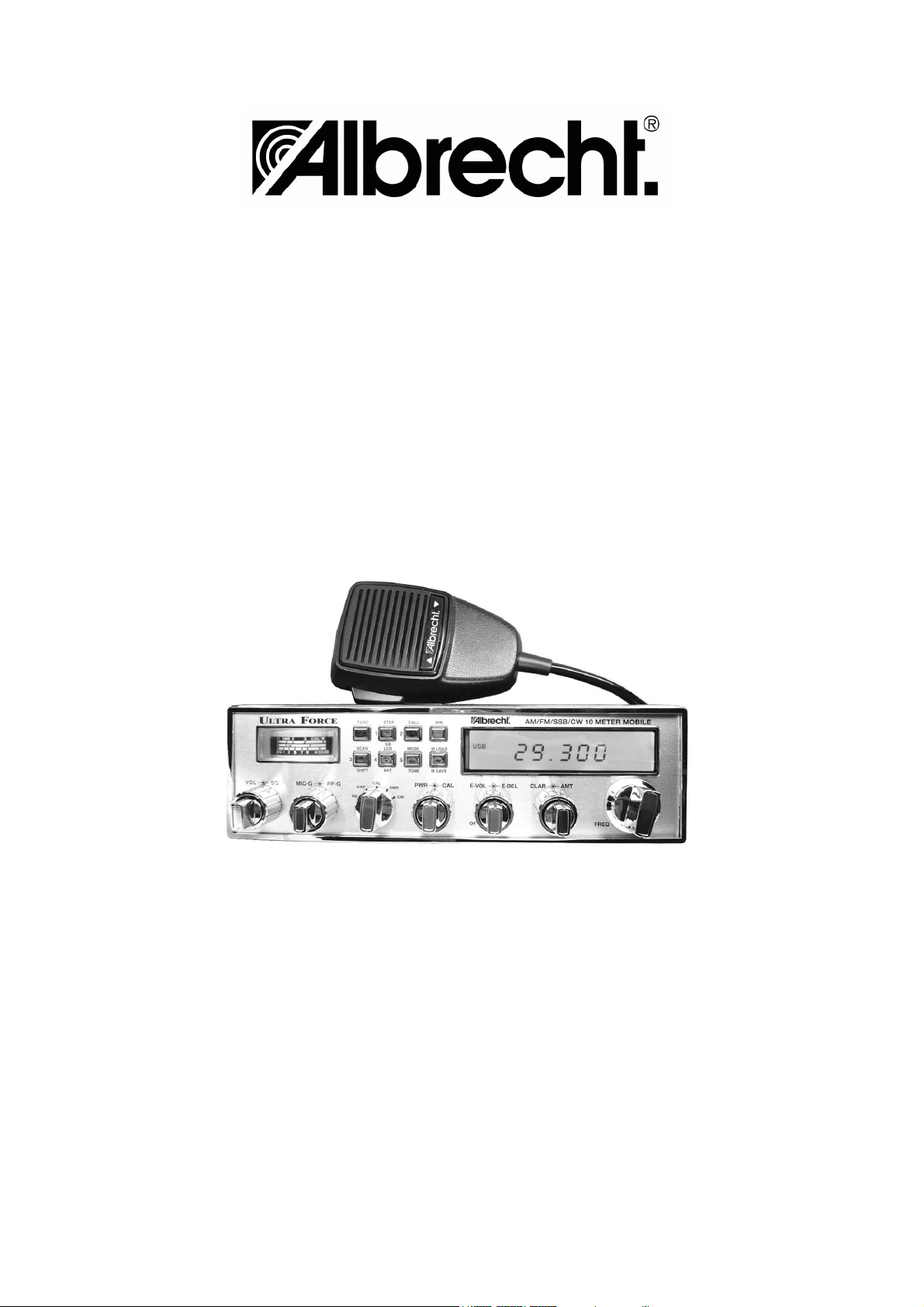
Congratulations on your purchase of this Albrecht UltraForce 10 meter FM/AM/SSB/CW transceiver. Your
transceiver is designed to provide years of enjoyment and trouble-free service. There are many features and
functions designed into this transceiver. To ensure that your investment is enjoyed to it’s fullest extent please
take a few moments and thoroughly read this manual.
Your UltraForce amateur radio transceiver is a microprocessor controlled, user programmable radio combining
both high RF performance with a user-friendly environment. The radio is built rugged to withstand years of use
in harsh mobile environments. Although engineered with mobile use in mind the radio, with the addition of a
high quality 10 Amp regulated power supply, may be easily adapted to fixed station operation.
Some of the features of the UltraForce are:
• an advanced design liquid crystal display that provides the operator with a full visual account of the
transceivers operating status,
• automatic frequency scanning from either the front panel or microphone, memory storage of your
favorite frequencies,
• programmable frequency resolution of either 1 kHz, 10 kHz or 100 kHz, and split (offset) frequency
operation for repeater use.
These are just a few of the features that make the UltraForce a pleasure to own and operate.
IMPORTANT: The UltraForce is designed for entry level amateur use. The transmitter of this radio can be
operated in most countries of the world only with a valid amateur radio operator’s licence.
If you are studying for your license and want to familiarize yourself with the operation of the radio, the receiver
may be operated with or without a licensed operator present under the condition, that essential parts of the
transmit section have been made temporarily inoperable.
Under no circumstances it is allowed to use this amateur radio as “CB-Transceiver” . Even licensed amateur
radio operators are not allowed to use this transceiver for CB radio purposes. The regulations require that a
dedicated notified or approved CB transceiver will be used for CB radio purposes.
2
Page 3

For more information regarding amateur licensing, contact your nearest amateur radio dealer, or for complete
details contact one of the world-wide amateur radio clubs, e.g. in Germany the “DARC-eV”. You can also find
more informations via www.darc.de
INSTALLATION
1. Contents
Unpack and inspect your UltraForce for missing or damaged components. Your UltraForce includes the
following items:
• UltraForce Transceiver
• Up / Down Microphone
• Mounting Bracket and Installation Hardware
• Power Cord
• Operating Manual
Install the UltraForce
Choose a location where there is easy access to all front panel controls and air circulation available to the rear
panel and aluminum heatsink. Do not install the transceiver in any compartment that restricts airflow. Attach
the mounting bracket to the vehicle first then mount the transceiver to the bracket. If the rear panel is not
easily accessible you may want to attach the power cord and antenna feed line prior to mounting.
Make Electrical Connections
The transceiver is designed to work on any 13.8 VDC power source with a negative ground. The condition of a
vehicle’s electrical system can affect operation. A low battery, worn generator/alternator, or poor voltage
regulator will seriously impair the performance of the transceiver.
Any of the above conditions could result in a high level of receiver noise generation or a substantial loss of the
transmitter’s RF output. Make sure that all of these components of your vehicle’s electrical system are in good
condition prior to installing the transceiver. Before making any electrical connections make sure the AF gain
(volume) control on the transceiver is in the “OFF” position. Connect the positive (+) red wire and negative (-)
black wire from the transceiver directly to the battery. Connecting directly to the battery has several benefits,
the first of which is to maximize RF output.
Secondly, the battery is a very large capacitor and will help eliminate certain types of ambient and vehicle
noise. Depending on your mounting location, additional power cable may be required. On additional runs of 2
m or less use 2.5 qmm stranded wire. Use thicker wire for longer longer runs.
CAUTION!
• ANY VOLTAGE EXCEEDING 15 VDC WILL DAMAGE THE RADIO
• MEASURE VOLTAGE AT BATTERY TERMINALS, WITH ENGINE RUNNING, PRIOR TO
INSTALLATION!
Legal information
The presently valid European “Automotive Directive” does not allow to operate this transceiver from the car’s
DC network in cars during motion.
Please do not use this transceiver while You are riding the car. However, the “Automotive Directive” is under
revision, and a new issue will soon again allow to use non-safety-relevant CE marked after-market equipment
in car installations. Because of EMC reasons, the car manufacturers have the right to issue installation rules
and instructions for installing transmitters and their antennas in cars. These rules and instructions are valid for
amateur radio installations as well as for any other transmitting device in cars.
Connect the Antenna
The transceiver will operate using any standard 50-ohm ground-plane, vertical, mobile whip, long wire or
similar antenna. The antenna should be rated at 50 watts PEP minimum. A standard SO-239 type connector is
provided on the rear panel of the transceiver. Connection is made using a PL-259 and high grade coaxial
cable (RG213 or RG58A/U is recommended).
A ground-plane antenna provides greater coverage and is recommended for fixed station-to-mobile operation.
3
Page 4
For point-to-point fixed station operation, a directional beam antenna operates at greater distances even under
adverse conditions. A non-directional antenna should be used in a mobile installation; a vertical whip is best
suited for this purpose. The base loaded whip antenna normally provides effective communications.
For greater range and more reliable operation, a full quarter wave whip may be used. Either of these antennas
use the metal vehicle body as a ground plane.
SWR Adjustment of the Antenna
After you have determined that the installation is correct and the radio is operational, it is important to
determine the antenna system’s SWR (Standing Wave Ratio). Prior to taking any measurements make
sure the SWR bridge (meter) is in good working order and is calibrated. To ensure your radio is performing
properly the SWR should never exceed 1.5 to 1. This is critical due to the high level of gain developed in the
RF deck. Never transmit on any antenna system where the SWR exceeds 1.8 to 1. This will stress the output
stage and could destroy the RF transistors; this type of misuse and failure is not covered under warranty.
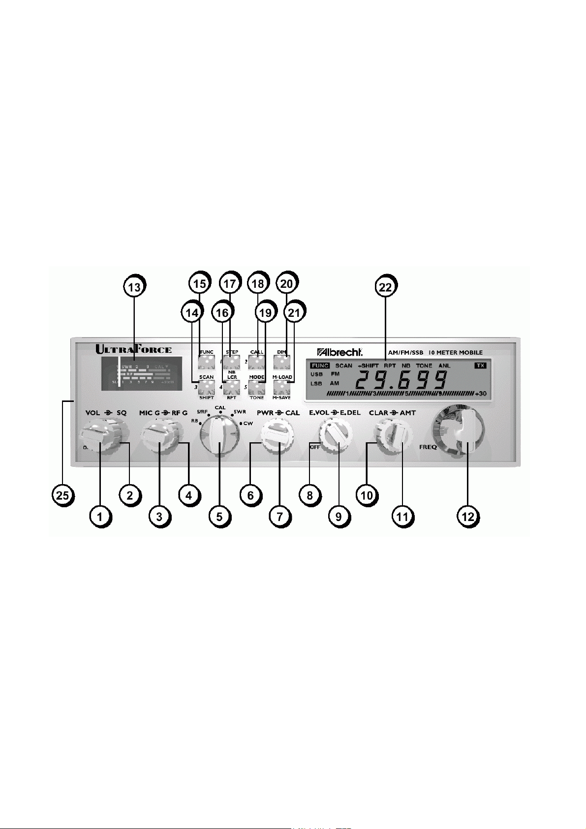
FRONT PANEL CONTROLS AND FUNCTIONS
Reference Front Panel Diagram
(1) POWER ON/OFF and VOLUME CONTROL
Turns the transceiver on and off, and adjusts the AF gain, or volume.
(2) SQUELCH CONTROL
Used to eliminate background or “white” noise when monitoring strong signals. Also used to activate SCAN
feature (see 14). To properly adjust squelch circuit, slowly rotate the control clockwise until the received audio
disappears. Now turn the control slightly counterclockwise - this will keep the threshold right on the edge so
you will not miss any incoming signals.
(3) MICROPHONE GAIN CONTROL
Increases or decreases the energy developed in the microphone amplifier circuit. The gain increases as the
control is rotated clockwise. For optimum setting, press the push-to-talk switch on the microphone (see 23)
and speak in a constant tone into the microphone. A good test tone is to say the word “four” in a long, drawn
out tone. While speaking, rotate the mic gain control clock-wise until the modulation LCD display reads
+30(see 22). Next, rotate the control counterclockwise until the +30 segment of the display starts to flicker.
4
Page 5

(4) RF GAIN CONTROL
Adjusts the receiver sensitivity to both signals and background noise. This affects the distance at which a
signal can be detected. Turning the control counter-clockwise reduces the receiver sensitivity. This is particularly useful in areas where large volumes of traffic (signals) are present.
(5) ROGER BEEP CONTROL
RB position activates the end of transmission, or roger beep, tone. When activated a 1 kHz tone will automatically transmit upon release of PTT switch (see 23). This notifies contacts that your transmission has
ended and you are ready to receive their signal. To turn off the roger beep, put the switch in the S/RF position.
NOTE: In the RB position, the meter (see 13) measures S/RF.
SIGNAL STRENGTH / RF METER CONTROL
S/RF position activates the meter (see 13) to measure receive signal strength and transmitter RF output
power.
CALIBRATE CONTROL
CAL position activates the meter to calibrate for SWR measuring. To calibrate for SWR, set the switch to the
CAL position, press the PTT switch (see 23) and rotate the calibrate control (see 6) until the meter (see 13)
needle lines up with the CAL mark on the far right side of the meter. Once lined up, release the PTT.
The transceiver is now ready to measure SWR.
NOTE:
When first attempting to calibrate make sure the transceiver is in the AM mode (see 19). If it is not possible
to calibrate in AM, then switch to FM mode.
STANDING WAVE RATIO CONTROL
SWR position activates the meter to measure the standing wave ratio of the transceiver and antenna system.
After the meter is calibrated, set the switch to the SWR position and press the PTT switch (see 23).
The meter (see 13) will measure the SWR. For optimum performance the SWR should be below 1.5 – the first
green segment on the SWR portion of the meter indicates an acceptable standing wave ratio.
CW
CW position activates a separate connected CW key to make transmissions in Morse Code /CW instead by
microphone.
(6) CALIBRATE CONTROL
Rotate to calibrate the meter (see 13) for SWR measurements. See instruction 5 for more information.
(7) RF OUTPUT POWER CONTROL
Continuously variable control for adjusting the RF output power of the transmitter in all modes for QRP
operation. To reduce the RF output power rotate the control counterclockwise. To increase rotate the control
clockwise. The power output is a linear control, therefore the peak to average output power ratios remain
constant regardless of power level.
(8) ECHO DELAY CONTROL
Varies the amount of delay, or duration of the echo repetition. Rotate clockwise to increase the amount of
delay and counterclockwise to decrease.
(9) ECHO ON/OFF and VOLUME CONTROL
Turns on and off the echo feature, and varies the volume or number of echo repetitions. To turn on the echo
feature and increase the echo volume, rotate the control clockwise. To turn off the echo feature rotate the
control completely counterclockwise to the OFF position.
(10)ALL MODE TALK BACK CONTROL
All Mode Talk Back is an independent talk back monitor. The AMT functions in all modes and allows the
operator to monitor the transmitted audio of the UltraForce. To increase the volume of the talk back rotate the
control clockwise. To decrease rotate counterclockwise. To turn off the talk back rotate the control completely
counterclockwise.
(11)CLARIFIER
Allows variation of the receiver operating frequency above and below the indicated frequency in all modes.
The receive clarifier is primarily used in tuning to an SSB signal. The receive clarifier has a range of +/-1
kHz above and below the indicated frequency.
5
Page 6

(12)FREQUENCY
Rotate clockwise to increase the operating frequency and counterclockwise to decrease the operating frequency.
(13)METER
The meter indicates receive signal strength, RF output power, SWR calibrate and SWR. The top horizontal
bar graph indicates calibration and measuring of the standing wave ratio. The center bar graph indicates RF
output power. The bottom bar graph indicates receive signal strength.
IMPORTANT!
Operating some of the features in 14 through 21 require the use of the function control. To activate
the function control, momentarily push the FUNC (15) control, the FUNC prompt will be displayed in
upper left-hand corner of LCD. Push the control again to deactivate the function control.
(14)SCAN
Scans frequencies in increments of 10 kHz. There are two ways to scan using front panel entry.
(1) Receive Audio On Scanning: Press the SCAN button. Scan rate is one step every 5 seconds. To stop
scanning press the SCAN button again, or momentarily press the PTT button on the microphone (scanning will
stop without transmitting).
(2) Receive Audio Mute Scanning: Carefully rotate squelch control to the threshold (see 2). The receiver scan
rate will now be five steps per second. When a signal is detected the squelch is automatically disengaged and
the scanning is paused. The squelch circuit will automatically reengage and the receiver will continue to scan
until to the moment the received signal is no longer detected. To stop scanning, press the SCAN button, or
momentarily press the PTT button on the microphone (scanning will stop without transmitting).
SHIFT
Used for programming offsets to operate repeater networks.
The UltraForce can transmit and receive on different frequencies.To program the offset, press the FUNC
button and hold down the SHIFT button for 3 or more seconds.
Three digits will appear on the LCD. This is the offset frequency in kHz. Rotate the FREQUENCY control until
the desired offset frequency is displayed. To return to the main display press the FUNC button and hold down
the SHIFT button for 3 or more seconds, or momentarily press the PTT button on the microphone (the
transmitter will not be engaged).
To activate the programmed offset frequency, press the FUNC button, and then press the SHIFT button
once. +SHIFT is displayed on the LCD. The UltraForce will now transmit on the frequency that is XXX kHz
greater than the displayed, or receive, frequency (XXX represents the programmed offset frequency in kHz
units).
To transmit on the frequency that is XXX kHz lower than the displayed, or receive, frequency press FUNC,
then the SHIFT button. Repeat this until -SHIFT is displayed on the LCD.
To disengage the programmed offset frequency, press the FUNC button and then press the SHIFT button.
Repeat this until the SHIFT indicator is no longer displayed on the LCD.
MEMORY CHANNEL 3
After programming this button is memory channel 3. See M.LOAD \ M.SAVE control for programming instructions.
(15)FUNCTION
This control is used to operate the functions that are printed below the control buttons. Press and release,
FUNC will be displayed on the LCD indicating that the function command is activated. After you have pressed
one of the buttons the FUNC will disappear from the screen.
(16)LAST CHANNEL RECALL
Press the LCR button to return to the last frequency that was transmitted on for more than 3 seconds.
REPEATER (interesting for USA repeaters only)
Repeater access tone on and off control. Most repeaters (in USA only) require an 88.5 Hz tone burst to
access. To activate the 88.5 Hz tone burst, press the FUNC control and then press the RPT button. RPT will
appear on the LCD indicating that the tone burst will now automatically be transmitted whenever the PTT is
pressed. To deactivate, repeat the same process.
6
Page 7

MEMORY CHANNEL 4
After programming, this button is memory channel 4. See M.LOAD \ M.SAVE control for programming instructions.
(17)STEP
The STEP button selects frequency resolution in either 1 kHz, 10 kHz or 100 kHz steps. Press the STEP
button, one of the digits will flash on and off. Press the STEP button again to change stepping resolution.
To tune frequencies in either 10 kHz or 100 kHz increments, press the STEP button until the desired digit is
flashing. Rotate the FREQUENCY control in either direction.
The entire frequency range of the UltraForce can be stepped through in 10 or 100 kHz increments.
To tune in 1 kHz increments, press the STEP button until the 1 kHz digit flashes on and off. Rotate the FREQUENCY control.
NOTE: When stepping in 1 kHz increments, you are limited to tuning within a 10 kHz frequency range.
NOISE BLANKER and AUTOMATIC NOISE LIMITER
Noise blanker on and off control. This circuit eliminates pulse type interference usually associated with automotive ignition systems. To activate the noise blanker, press the FUNC control and then press the NB button.
NB will appear on the LCD indicating the noise blanker is turned on. To turn off the noise blanker, repeat the
same process.
MEMORY CHANNEL 1
After programming, this button is memory channel 1. See M.LOAD \ M.SAVE control for programming instructions.
(18)CALL
The USA national call frequency for SSB is 28.400 MHz. The radio’s operating frequency is automatically
reset to this frequency when the CALL button is pressed.
MEMORY CHANNEL 2
After programming this button is memory channel 2. See M.LOAD \ M.SAVE control for programming instructions.
(19)MODE
Each time the button is pressed the operating mode is changed. The operating mode is indicated on the liquid
crystal display: AM, FM, USB, or LSB.
TONE LOW
To activate the tone low feature, press the FUNC button, and then press the T. Low button to turn on the
receive audio tone control. LOW will appear on the LCD when the low tone is activated. This feature will roll-off
high frequency noise (i.e. “white” noise). Under many operating conditions this will improve the clarity and
understanding of received signals.
MEMORY CHANNEL 5
After programming this button is memory channel 5. See M.LOAD \ M.SAVE control for programming instructions.
(20)DIMMER
Press the DIM, or dimmer control to decrease the amount of back-lighting on the front panel and LCD screen.
(21)MEMORY SAVE
To save in memory a specific frequency and operating mode, select the desired mode and rotate the
FREQUENCY control to the desired frequency. Press the FUNC button, and then press the M.SAVE button. S
will appear on the LCD next to the frequency. While S is displayed, immediately press any of the memory
channel buttons (1 - 5). The mode and frequency is now saved into memory. If the S indicator disappears
before you press the memory channel button, the information will not be saved and the process must be
repeated.
MEMORY LOAD
To load, or recall, any of the saved memory channels press the M.LOAD button. L will appear on the LCD for
several seconds. While the letter is displayed press the desired memory channel button (1 - 5). The programmed mode and frequency will be displayed.
7
Page 8

(22)LIQUID CRYSTAL DISPLAY
The LCD screen is the status display for the majority of the transceiver’s functions.
(3) +SHIFT \ -SHIFT
Indicates that the split or offset frequency function is activated.
(4) RPT
Indicates that the repeater access tone burst function is active.
(5) NB and ANL
Indicates that both the noise blanker and the automatic noise limiter are active.
(6) TONE
Indicates that the receive audio tone low feature is active.
(7) 5 DIGIT FREQUENCY DISPLAY
Indicates transmit and receive operating frequencies.
(8) TX
Indicates that the transmitter is on.
(9) USB \ LSB \ FM \ AM
Indicates the selected operating mode.
(10) PEAK READING RF POWER METER
Indicates relative peak RF output power.
(23)PUSH-TO-TALK (PTT) CONTROL
Activates the transmitter and/or receiver. Push and hold the PTT control to transmit. Release the PTT control
to receive.
(24)UP and DOWN FREQUENCY CONTROLS
Allows remote control of frequency control. Press the up arrow to increase in frequency and press the down
arrow to decrease in frequency.
8
Page 9

(25)MICROPHONE INPUT JACK (not shown)
6-pin, lock ring type, microphone connector located on side chassis of transceiver.
Mic wiring is as follows:
Pin 1 : Microphone Audio
Pin 2 : Receive
Pin 3 : Transmit
Pin 4 : Down (Up w/ 22K Ohm Resistor)
Pin 5 : Ground
Pin 6 : +13.8 VDC
(26)EXTERNAL SPEAKER JACK (not shown)
External speaker jack, marked EXP SP, is located on the rear panel of transceiver. For use with 4 to 8 ohm
external speaker.
(27) CW KEY JACK (not shown)
The CW key jack is located on the rear panel. The CW Key is used for Morse Code transmission. You will
need a 3.5mm Mono connector.
OTHER FEATURES
PROGRAMMING KEY TONE
This tone sounds each time the CPU is being programmed. It is helpful, in the beginning so you can be sure
the command has been entered. You may eliminate the tone by simply pressing the PTT switch while turning
on the ON/OFF POWER switch.
(1) FUNCTION
Indicates the function button has been activated and that the function dependent controls may be accessed.
(2) SCAN
Indicates that the transceiver is in scan mode..
9
Page 10

TECHNICAL SPECIFICATIONS
TRANSMITTER
Frequency Range: 28.000 - 29.699 MHz
Tuning Steps: 1 kHz, 10 kHz, 100 kHz
Emission Types: LSB, USB (J3E), AM (A3E), FM (F3E), CW
Carrier Suppression: Better than 40 dB below peak output
Unwanted Sideband Suppression: Better than 50 dB below peak output (1 kHz tone)
Spurious Radiation: Better than 50 dB below peak output
Frequency Accuracy: Better than +10 ppm from 0 – 40° C after 15 minute warm up
Modulation Type: J3E: Balanced Modulator
A3E: Voltage Modulator
F3E: Frequency Modulator
Maximum FM Deviation: +/-2 kHz
Output Impedance: 50 ohms (nominal), unbalanced
Microphone Impedance: Dynamic, 600 ohms
Power Consumption: 6 amps maximum
Power Output: FM: 30 Watts (Max.)
AM: 8 Watts Average (Max.)
SSB: 30 Watts Peak (Max.) PEP
RECEIVER
Frequency Range: 28.000 - 29.699 MHz
Circuit Type: Superheterodyne, Dual Conversion
Clarifier Range: +/-1.0 kHz
Sensitivity: SSB and AM 0.25uV
(SSB and AM figures measured for 10 dB S+N/N)
FM better than 0.3uV for 12 dB SINAD
Minimum discernable signal -135 dBm
Intermediate Frequencies: 1st IF: 10.695 MHz
2nd IF: 455 kHz
SSB IF: 10.695 MHz
Image Rejection: Better than 70 dB
IF Rejection: Better than 80 dB for all frequencies
Selectivity: -6 dB -60 dB
SSB: 4.2 kHz 8.5 kHz
AM, FM: 6.0 kHz 18 kHz
Noise Blanker: All mode, seven stage high gain type
Dynamic Range: Better than 100 dB
Audio Output Power: 2 watts minimum (into 8 ohms, with less than 7% THD)
Audio Output Impedance: 8 - 16 ohms
Power Consumption: 500 milliamps
Dimensions: 7.75(L) x 10.75(W) x 2.5(H) Inches
© ALAN Electronics GmbH
Daimlerstr. 1 k D-63303 Dreieich
www.albrecht-online.de www.alan-germany.com
Service Hotline (+49) 06103 9481-30
Service Fax (+49) 06103 9481-60
e-mail service@alan-germany.com
Service-Download www.hobbyradio.de
10
Page 11

Declaration of Conformity
We hereby declare that our product:
10 m Amateur Radio AM/FM/SSB/CW Transceiver
Brand: Albrecht Model: UltraForce
satisfies all technical regulations applicable to the product within the scope of EU Council
Directives and harmonised European Standards:
73/23/EEC, 89/336/EEC and 99/5/EC
ETS 301 489-01 / EN 301 489-15
EN 301 783-2, EN 60 950
All essential radio test suites have been carried out.
MANUFACTURER:
ALAN Electronics GmbH
Daimlerstr. 1 k
63303 Dreieich
GERMANY
This declaration is issued under the sole responsibility of the manufacturer according to the
procedure of Annex III R&TTE directive. Basing on this declaration, the amateur radio may be
used only by authorized persons having a valid amateur radio licence, and only for the purpose
of amateur radio service in the dedicated frequency ranges.
Point of contact: Wolfgang Schnorrenberg
Place and date of issue: Dreieich, 21.1.2004
(Signature)
Dipl.-Phys. Wolfgang Schnorrenberg
ALAN Electronics GmbH
 Loading...