

Page 1
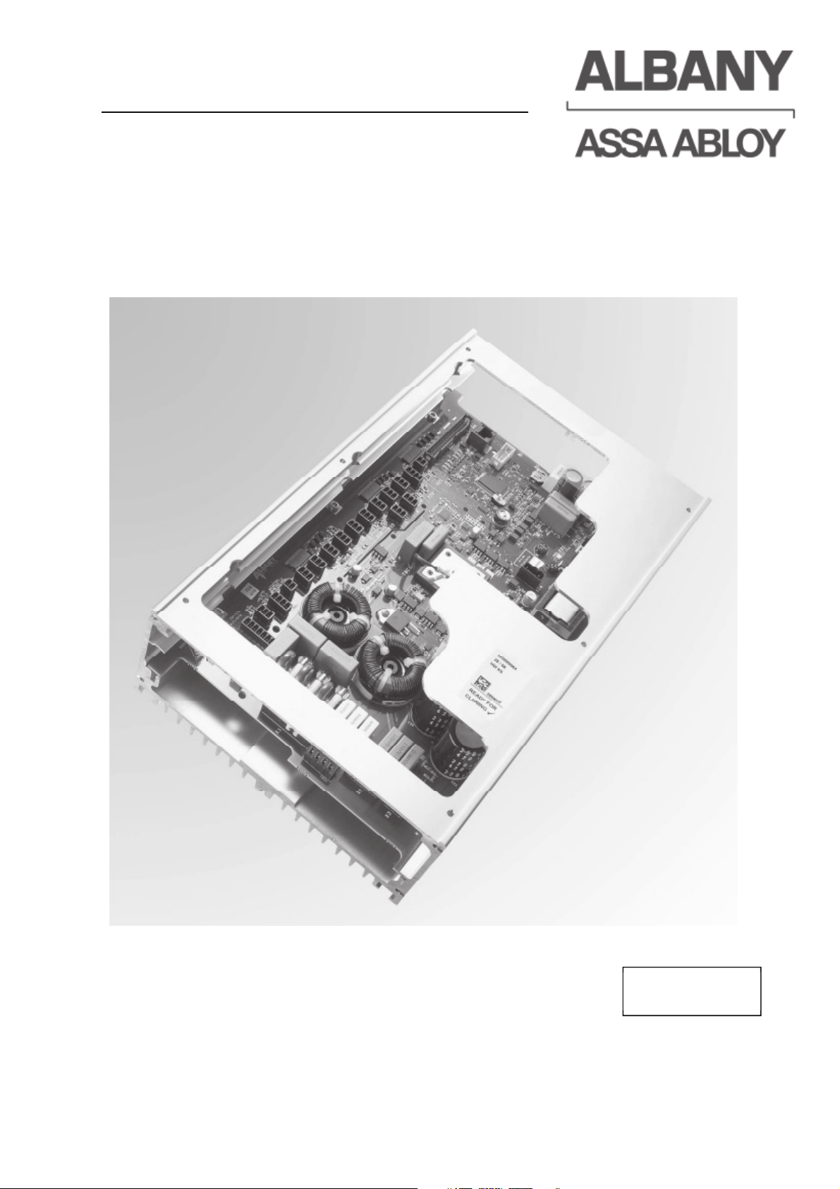
Operating instructions
MCC
VectorControl
6410R0046
Page 2

2011 ALBANY Door Systems GmbH.
All rights to the control system and the related operating instructions are protected.
Legal action will be taken in case of imitation or copying.
These operating instructions may not be reprinted or otherwise reproduced without
the written consent of ALBANY Door Systems.
The general terms and conditions of ALBANY Door Systems GmbH are applicable.
ALBANY Door Systems reserves the right to make technical changes.
These operating instructions are an integral part of the door. The original version of
the operating instructions is in German.
Manufacturer
ASSA ABLOY Entrance Systems AB
Lodjursgatan 10
SE-261 44 Landskrona
Sweden
Internet: www.albanydoors.com
Email:
Page 3

Contents
1
Introduction ............................................................................................................... 7
1.1
Applicable documents ................................................................................................. 7
1.2
Declaration of conformity ............................................................................................ 7
1.3
Amendments and validity ............................................................................................ 7
1.4
Document storage ....................................................................................................... 7
1.5
Target group ............................................................................................................... 7
2
Safety instructions .................................................................................................... 8
2.1
General safety instructions ......................................................................................... 8
2.2
Safety instructions for operating the door ................................................................... 9
2.3
Safety instructions for installation and maintenance ................................................... 9
2.4
Safety instructions for “hold to run mode” ................................................................... 9
3
Product Description ................................................................................................ 10
3.1
MCC main unit with control box ................................................................................ 10
3.1.1Safety devices of the control system ......................................................................... 11
3.1.1.1Testing the safety devices ........................................................................................ 11
3.1.1.2Electrical safety edge (only for some types of door) ................................................. 11
3.1.1.3Pre-running safety photocell (only for some door types) ........................................... 11
3.1.1.4Door line photocell .................................................................................................... 12
3.1.1.5Emergency stop ........................................................................................................ 12
3.1.2Operating modes ...................................................................................................... 12
3.1.2.1Open by impulse / close after time ............................................................................ 12
3.1.2.2Toggle circuit / manual closing .................................................................................. 13
3.1.2.3Close after passage function .................................................................................... 13
3.1.2.4Hold to run mode ...................................................................................................... 13
3.1.2.5Interlocking ............................................................................................................... 13
3.1.2.6Airlock function.......................................................................................................... 13
3.2
MCC - Display ........................................................................................................... 14
3.2.1Use of MCC - Display ............................................................................................... 14
3.2.2Save the input ........................................................................................................... 15
3.2.3Exit the input ............................................................................................................. 15
3.2.4Access codes MCC - Display .................................................................................... 15
4
Installation ............................................................................................................... 16
4.1
Mechanical installation of the control system ............................................................ 16
4.2
Electrical installation of the control system ............................................................... 16
4.2.1Electrical installation requirements............................................................................ 16
4.2.2Cross-section wiring / plug-in terminals .................................................................... 17
4.2.2.1Handling recommendation terminal blocks ............................................................... 17
4.2.3Ferrite at the display cable ........................................................................................ 17
4.3
Wiring restrictions ..................................................................................................... 18
4.4
Terminal assignment of the control system ............................................................... 19
4.5
Emergency manual lever / emergency hand crank contact selection ....................... 21
4.6
Reference limit switch ............................................................................................... 21
4.7
Setting door limits ..................................................................................................... 22
4.7.1Setting door limits for doors without displays ............................................................ 22
6410R0046_UM_Setup-Operation_MCC_EN11.docx 2012-07-16 3
Page 4

4.7.2Setting door limits for doors with displays .................................................................. 22
4.8
Correcting the lower end position [1] ......................................................................... 24
4.9
Setting the reduced opening height [1] ...................................................................... 24
4.10Setting the hold-open time [1] .................................................................................... 25
4.11Setting the pre-running time before closing [1] .......................................................... 25
4.12Setting the pre-running time before opening [1] ......................................................... 25
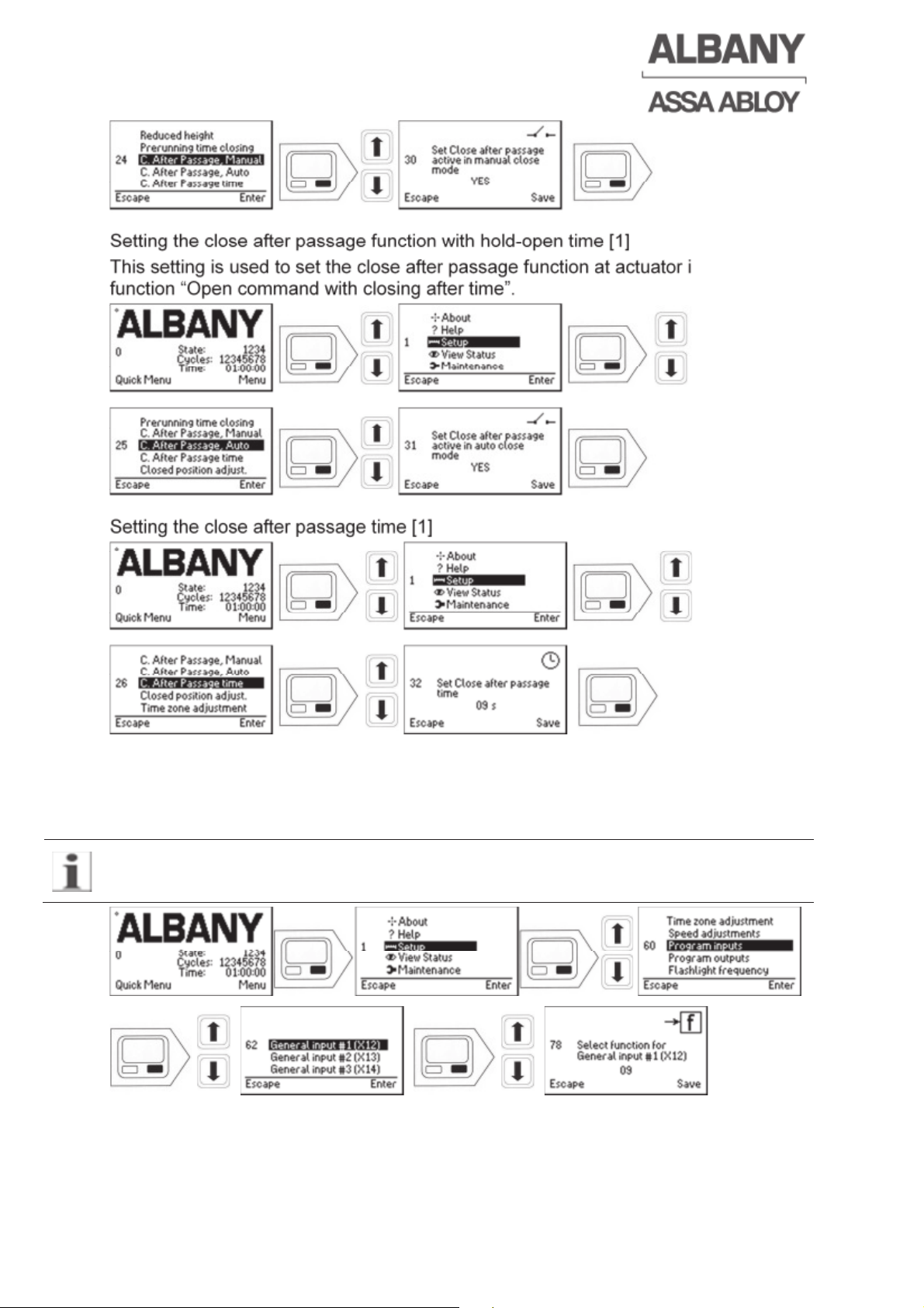
4.13Close after passage function ..................................................................................... 25
4.13.1Setting the close after passage function without hold-open time [1] .......................... 25
4.13.2Setting the close after passage function with hold-open time [1] ............................... 26
4.13.3Setting the close after passage time [1] ..................................................................... 26
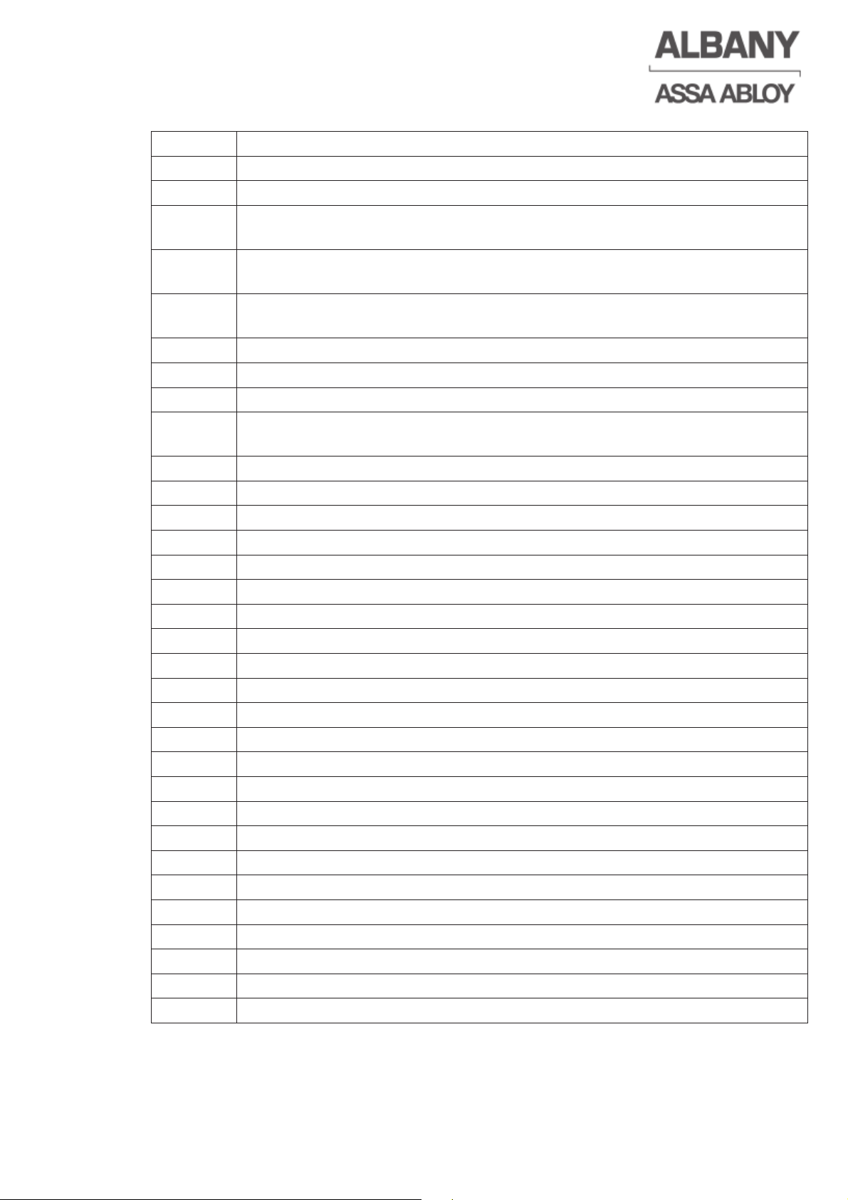
4.14Programming the inputs [1]........................................................................................ 26
4.15Programming the outputs [1] ..................................................................................... 28
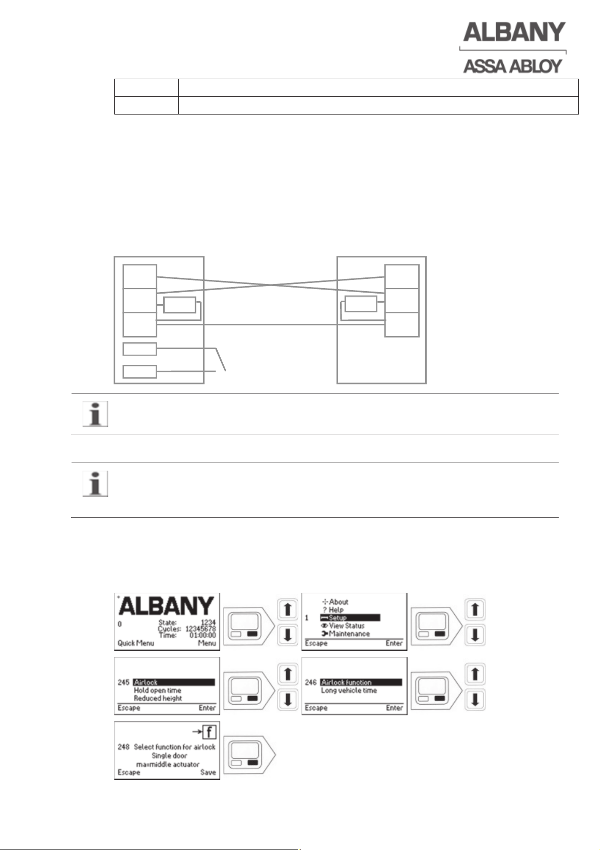
4.16Airlock function [1] ..................................................................................................... 29
4.16.1Airlock wiring ............................................................................................................. 29
4.16.2Setting the airlock function [1] .................................................................................... 29
4.16.3Setting the long vehicle time [1] ................................................................................. 30
4.17Reducing the speed [2] .............................................................................................. 30
4.17.1Reducing the opening speed [2] ................................................................................ 30
4.17.2Reducing the closing speed above an opening height of 2.5 m [2] ............................ 31
4.17.3Reducing the closing speed below an opening height of 2.5 m [2] ............................ 31
4.18Adjustment of activations of the safety edge or pre running photocell [2] .................. 31
4.19Activating reference search after a power failure [2] .................................................. 32
4.20Altering the traffic light function [1] ............................................................................. 32
4.21Altering the flashing light function [1] ......................................................................... 32
4.22Setting the flash rate of the flashlight [1] .................................................................... 33
4.23Emergency exit doors – set time for regular self-test [1] ............................................ 33
4.24Setting the time zone [1] ............................................................................................ 33
4.25Setting of the time [1] ................................................................................................. 34
4.26Setting of the date and time [2] .................................................................................. 34
4.27Changing the main or supply voltage [2] ................................................................... 35
4.28Changing the main supply voltage frequency [2] ....................................................... 36
4.29Changing the brake voltage [2] .................................................................................. 36
4.30Change customer code [2]......................................................................................... 36
4.31Querying the door positions and the state history [0] ................................................. 37
4.32Setting endurance test [2] .......................................................................................... 37
4.33Reset service interval [1] ........................................................................................... 38
5
Operation .................................................................................................................. 39
5.1
Safety instructions ..................................................................................................... 39
5.2
Display ....................................................................................................................... 39
5.3
Switch-on and reference run ...................................................................................... 39
5.4
Opening the door ....................................................................................................... 40
5.5
Closing the door ........................................................................................................ 40
5.6
Stop the door ............................................................................................................. 41
5.7
Power failure .............................................................................................................. 41
5.8
Emergency manual operation .................................................................................... 41
6410R0046_UM_Setup-Operation_MCC_EN11.docx 2012-07-16 4
Page 5

5.9
Service interval ......................................................................................................... 42
5.10Permanent opening of the door [1]............................................................................ 43
5.11Deactivation of Interlock function [1] ......................................................................... 43
5.12Crash-system ............................................................................................................ 43
5.12.1Auto-repair crash system: ......................................................................................... 44
5.12.2Manually repairable crash system:............................................................................ 44
5.13Thermal switch .......................................................................................................... 44
5.14Airlock function [1] ..................................................................................................... 44
5.14.1Airlock sequence [1] .................................................................................................. 44
5.14.2Airlock passage from A to B with middle actuator ..................................................... 45
5.14.3Airlock passage from A to B without middle actuator ................................................ 45
5.14.4Long vehicle function at doors with middle actuator.................................................. 46
5.14.5Manual long vehicle function ..................................................................................... 46
5.14.6Permanent opening function ..................................................................................... 46
5.14.7Direction detecting red traffic light on the outside of the airlock door ........................ 46
5.14.8Actuators and time setting ........................................................................................ 47
6
Fault correction ....................................................................................................... 48
6.1
Checking the inputs and outputs ............................................................................... 48
6.2
Error log readout ....................................................................................................... 48
6.3
Event log readout ...................................................................................................... 51
6.4
Clear error log [3] ...................................................................................................... 52
6.5
Altering the error mask [3] ......................................................................................... 52
6.6
Error messages / error codes (only for doors without display) .................................. 52
6.7
Error messages (only for doors with displays) .......................................................... 53
6.8
Hardware and software version readout ................................................................... 58
6.9
Keypad test ............................................................................................................... 59
6.10Technical support ...................................................................................................... 59
6.11Clone function when replacing the control system .................................................... 59
7
Technical data and control system label .............................................................. 61
7.1
General data ............................................................................................................. 61
7.2
Classifications of safety circuits to EN ISO 13849-1 ................................................. 62
7.3
Labeling .................................................................................................................... 62
8
Optional MCC – Units ............................................................................................. 63
8.1
Flange plate with integrated junction box .................................................................. 63
8.1.1Connector assignment junction box .......................................................................... 63
8.2
Interface board .......................................................................................................... 64
8.2.1Terminal assignment of the interface board .............................................................. 64
8.2.2Schematic electrical drawing of the interface board: ................................................. 66
8.3
MCC extension ......................................................................................................... 67
8.3.1Mechanical installation of the MCC extension .......................................................... 67
8.3.2Terminal assignment of the MCC extension board ................................................... 68
8.3.3Plug-on modules for MCC extension ........................................................................ 69
8.3.3.1Radio receiver 433 MHz ........................................................................................... 70
8.3.3.2Loop detectors .......................................................................................................... 70
8.3.3.3Setting the slide switches for plug-on modules ......................................................... 70
6410R0046_UM_Setup-Operation_MCC_EN11.docx 2012-07-16 5
Page 6

8.4
Uninterruptible power supply (UPS) .......................................................................... 71
8.4.1Wiring the UPS to the MCC ....................................................................................... 72
8.4.2Parameterisation of the MCC .................................................................................... 72
8.4.2.1Programming an output to give a control signal to the UPS ...................................... 72
8.4.2.2Configure the MCC for the UPS function ................................................................... 73
8.5
Single-Phase Combibox ............................................................................................ 73
8.5.1Parameterisation of the MCC for single phase main supply ...................................... 74
8.6
EMC filter ................................................................................................................... 74
8.7
Field bus module ....................................................................................................... 75
8.7.1Structure of field bus module ..................................................................................... 75
8.7.1.1Mainboard.................................................................................................................. 76
8.7.1.2Profinet 1-Port ........................................................................................................... 76
8.7.1.3Profinet 2-Port ........................................................................................................... 76
8.7.1.4Profibus ..................................................................................................................... 76
8.7.2Set Fieldbus Address ................................................................................................ 77
8.7.3Generic Station Description (GSD-file) ...................................................................... 77
8.7.4Ethernet/IP ................................................................................................................. 77
8.7.4.1Setup of the Ethernet/IP-Master ................................................................................ 77
8.7.5Bus communication ................................................................................................... 77
8.7.6TX data from the MCC ............................................................................................... 77
8.7.6.1Application Data Instance ADI[0] ............................................................................... 77
8.7.6.2Application Data Instance ADI[1] ............................................................................... 78
8.7.6.3Allocation of the MCC error messages ...................................................................... 78
8.7.6.4Byte order Profibus and Profinet IO ........................................................................... 79
8.7.7RX data, data to the MCC.......................................................................................... 79
8.7.7.1Application Data Instance ADI[2] ............................................................................... 79
8.7.7.2Application Data Instance ADI[3] ............................................................................... 80
8.7.7.3Byte order Profibus and Profinet IO ........................................................................... 81
8.7.8Installation of the safety relays (Option for machine protection doors) ...................... 81
6410R0046_UM_Setup-Operation_MCC_EN11.docx 2012-07-16 6
Page 7

1 Introduction
These operating instructions apply to the use of the frequency converter control
system MCC Vector Control with high speed doors. They are part of the product and
describe the intended and safe use throughout the whole product life cycle.
Before the installation of the MCC read the installation and operating instructions
carefully and familiarize yourself with their contents.
The manufacturer is not liable for damage caused by not observing of the operating
instructions as well as their safety instructions, or a not intended use of the MCC.
1.1 Applicable documents
These operating instructions are only valid in combination with the operating
instructions for the RapidRoll high-speed door and the inspection book. Both of these
documents are supplied with the product.
1.2 Declaration of conformity
The control unit is an integral part of the door. The declaration of conformity applies
to the high-speed door as well as the control unit. It is included in the inspection book
supplied with the door.
The control unit is designed in compliance with the requirements of the EN 13241-1
standard for door products and the subordinate standards mentioned in this
standard.
Modifications that affect the technical data specified in the operating instructions or
intended use, i.e. modifications that materially alter the machine, invalidate the
manufacturer’s declaration of conformity.
1.3 Amendments and validity
The information contained in these instructions constitutes the technical
specifications applicable at time of publication. Significant changes will be
incorporated in a new edition of the operating instructions. The document and version
number of these instructions can be found in the footer.
1.4 Document storage
Keep these operating instructions in the storage bag inside the control cabinet or in
the supplied document box.
1.5 Target group
These operating instructions are addressed to trained, qualified and authorised
personnel. All setup configurations, and in particular repairs and maintenance, may
only be performed by employees of the manufacturer or other trained specialists.
6410R0046_UM_Setup-Operation_MCC_EN11.docx 2012-07-16 7
Page 8

2 Safety instructions
Before installation, operation, service, or maintenance work on this high speed door
or their electrical components it is mandatory to read and to comply with the safety
instructions.
In addition to the general safety instructions in this section, always observe the safety
instructions related to specific actions that are included in other sections. In
particular, the general safety instructions in the operating instructions for the door are
also applicable.
A nonobservance of these safety instructions can lead to damage of the door, injury
or death.
2.1 General safety instructions
• Observe the general, legal and other national valid regulations for accident
prevention and acknowledged technical rules for safety-oriented work.
• All work on electrical systems and connections may only be performed by
qualified personnel with appropriate authorisation.
• The electrical work must be carried out according to the applicable local
standards and legal regulations.
• Before performing any work on the control unit, cables, connectors or electrically
live components, always switch off and lock the main switch or disconnect and
secure the CEE plug.
• The door may be only operated, if the door is equipped with a disconnect device
for the main supply voltage (such as a suitable main switch or a CEE plug). The
main power disconnect device must be easily accessible and located between 0.6
and 1.7 meters above the access level.
• Make no change to the control or the safety devices which may affect the safety
of the door.
• In order to avoid damages by electronic discharge, the circuit board of the control
system and of the display should not be touched without appropriate ESD
protective equipment.
• Some parameters are protected by an access code for safety reasons. The
necessary access code level is given in square brackets after the chapter
heading. Detailed information about the access code can be found in chapter
3.2.4.
6410R0046_UM_Setup-Operation_MCC_EN11.docx 2012-07-16 8
Page 9

2.2 Safety instructions for operating the door
• The door is assembled in accordance with the installation instructions.
• All wiring between the door, the control unit and the drive is connected properly.
• All safety devices and protection equipment are installed as intended use and are
functional.
• Safety devices are not modified or out of operation.
• The user must be instructed to leave the main power on at all times, to avoid the
build-up of condensation in the control system housing.
2.3 Safety instructions for installation and maintenance
• Ensured that neither people nor vehicles pass through the door or are in the door
hazard area during installation and maintenance.
• Dangerous touch voltage applies at the control up to 30 seconds after switching
off/disconnecting the supply voltage (discharge of the capacitors). Therefore wait
min. 30 seconds before working on electrical parts, wiring or opening the MCC.
The non-observance can lead to an electric shock with serious injuries or death.
• A dangerous voltage at the MCC is applied after switching off/disconnecting the
MCC power supply in case of doors with an uninterruptible power supply (UPS).
The following instructions must be observed carefully:
Ö Switch off the main switch of the UPS as well.
Ö For working inside the UPS, the internal switch must be switched off (observe
the operating instructions for the UPS).
Ö The non-observance can lead to an electric shock with serious injuries or
death.
• Touching of electronic components on the MCC Board should generally be
avoided.
• When opening the housing cover of the MCC the control system must be
protected against moisture.
2.4 Safety instructions for “hold to run mode”
• In hold to run mode all safety devices are disabled. The door moves as long as
the opening or closing button is pressed and the door has not reached the upper
or lower end position. The door does not switch off until it reaches the upper or
lower end position.
• Do not operate the door if any person or object is located in the door hazard area.
• Operate the door only if door area is visible.
6410R0046_UM_Setup-Operation_MCC_EN11.docx 2012-07-16 9
Page 10
3 Product Description
The MCC control system is designed to be used with high speed doors. The MCC
meets the valid and applicable European CE and American/Canadian UL
requirements, which has been tested and confirmed by independent testing
institutes. The control system contains all necessary components to operate these
doors with consideration of all safety criteria.
The characteristics of the MCC Control System with Vector Control allow even
smoother starting and stopping of doors than is possible with standard frequency
converters. This protects the door’s mechanism against hard impacts and increases
its speed.
3.1 MCC main unit with control box
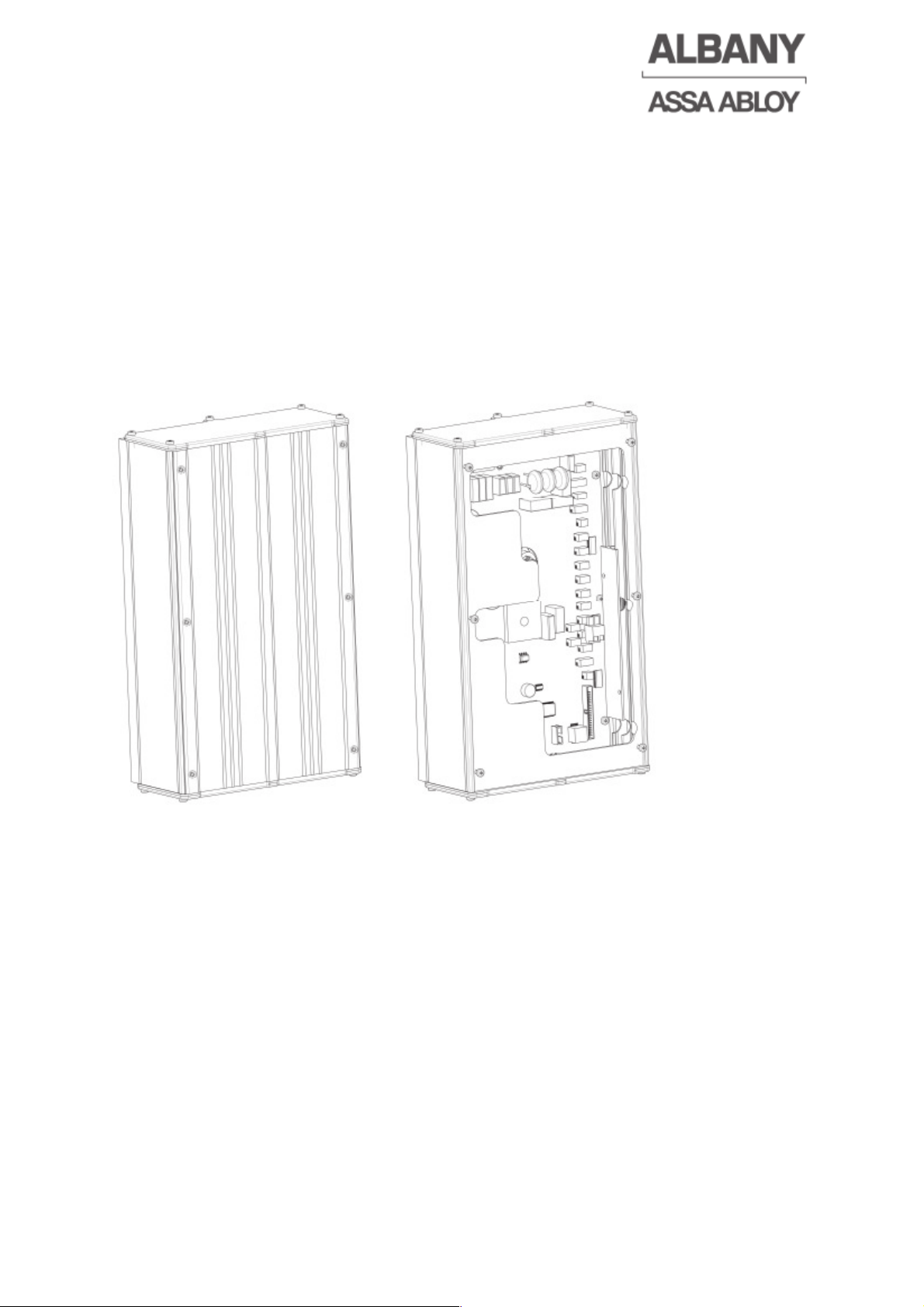
Figure 1: Control box MCC closed Figure 2: Control box MCC opened
The door control is built in an anodized aluminium housing. There is a connecting
plate at each end for the introduction of the cables and for the junction box to be
mounted.
Inside the housing (see Figure 2) the following components are located on the control
board:
• The plug-in connection terminals for the inputs and outputs of the control system.
• The connection terminals for the net or primary supply power, motor and the
brake cables
• The frequency converter including heat sink
• The short-circuit-proof power supply for the supply of the complete
microprocessors, the frequency converter and external 24 V loads.
• Brake control
6410R0046_UM_Setup-Operation_MCC_EN11.docx 2012-07-16 10
Page 11
6410R0046_UM_Setup-Operation_MCC_EN11.docx 2012-07-16 11
3.1.1 Safety devices of the control system
The closing sequence of an automatic door is monitored by various safety devices in
order to avoid accidents. The safety devices and functions incorporated in the control
unit are described below.
The doors are also equipped with other safety devices, depending on the door
model. See the 'Safety Systems' section of the RapidRoll user manual for information
on the safety devices provided with the various models.
As electric safety devices, a pre-running safety photocell or an electrical safety edge
can be used, which are complemented by a door line photocell in the side frame.
The electrical safety circuits of the MCC control system fulfil the requirements of the
product standard for doors EN 13241-1.
3.1.1.1 Testing the safety devices
Before each closing movement of the door the fault free operation of the safety
devices and the door line photocell are tested. If a fault is detected, no release of the
closing movement occurs and an error message is displayed by the control. In case
of an error the control changes in the hold to run mode, which allows the manual
operation of the door.
Observe the safety instructions for “hold to run mode” (chapter 2.4).
3.1.1.2 Electrical safety edge (only for some types of door)
The electrical safety edge serves as closing edge protection. It consists of a rubber
profile fitted to the main closing edge of the door. Any deformation of the rubber
profile initiates an electrical impulse. This impulse immediately stops the door while it
is closing and reverses regardless of the set opening height, up to the reference limit
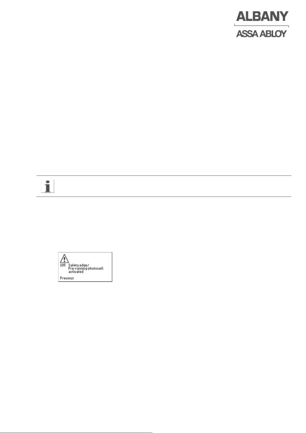
switch and is locked there. Locking is indicated by the following message on the
display.
Pressing the “Open” or “Close” buttons releases the locking of the door.
However, the function can be adjusted such that the door automatically closes after a
set time after the electrical safety edge has been activated (chapter 4.18).
Just before the lower end position of the door (max. 50 mm – 2”) the electrical safety
edge is switched off because otherwise an activation via the ground would take
place.
The MCC input for this fulfils the requirements of Category 2, Performance Level d of
the EN ISO 13849-1.
3.1.1.3 Pre-running safety photocell (only for some door types)
The pre-running photocell runs approx. 100 mm (4”) below the bottom profile
(depending on the door type). It moves with the door as it opens and closes. It
retracts into the bottom profile when the door is in the lower end position. Just before
the lower end position of the door (max. 50 mm – 2”) the prerunning photocell is
switched off because otherwise an activation via the ground would take place.
Page 12

6410R0046_UM_Setup-Operation_MCC_EN11.docx 2012-07-16 12
If the pre-running photocell is activated while the door is closing the door stops
immediately and then opens again until it reaches the reference limit switch
(reversing). After the tenth activation of the pre-running photocell (without the door
closing completely) the door will be locked in the upper end position. It is however
possible to parameterize the function differently (chapter 4.18).
The MCC input for this fulfils the requirements of Category 2, Performance Level d of
the EN ISO 13849-1.
3.1.1.4 Door line photocell
The door line photocell is mounted in the lower area of the side frame of the door
where it is protected. The proper function is monitored also by the control system. An
activation of the photocell while the door is open resets and starts the hold-open time
or the close after passage time. An activation of the photocell while the door is
closing the door stops immediately and then opens again until it reaches the
reference limit switch (reversing). Unlike for the electrical safety edge the door is not
locked in this end position, instead it closes again automatically after the hold-open
or close after passage time, if the door was closing in auto close mode while the
photocell was activated. Otherwise it will stay open. As an option it’s possible to get
at some door types a light curtain instead of the door line photocell.
3.1.1.5 Emergency stop
The MCC control unit has provision for connecting two emergency stop devices
corresponding to Stop Category 0 (stopping by immediate interruption of the power
supply to the motor).
The MCC input for this fulfils the requirements of Category 3, Performance Level d of
the EN ISO 13849-1.
3.1.2 Operating modes
The control unit has several operating modes, which can be selected by means of
the menus. The following are the main operation modes.
3.1.2.1 Open by impulse / close after time
After an Open impulse, the door travels until it reaches the door open end position.
The closing sequence starts after the hold-open time expires. The door closes until it
reaches the lower end position. The hold open time can be configured during setting
door limits (chapter 4.7.1 or 4.7.2) or separately (chapter 4.10).
If the door is closed, an Open impulse from the external impulse activator or the
Open button on the display initiates the door to open immediately. If the door is open,
the Open impulse restarts the hold-open time.
By a Stop command, either external or on the display, the door stops immediately
and remains in this position until an operation of the door in the desired direction is
initiated by an impulse activator. The display stop can be acknowledged only by an
up or down to command on the display, the display stop is not acknowledged by
external actuators.
If the door is in the fully opened state, a Stop signal terminates automatic closing and
the door remains open until the next impulse. If this is followed by a Close impulse,
the closing sequence starts immediately. An Open impulse restarts the hold-open
time and initiates the door to close automatically after the time expires.
Interruption of the door line photocell or other safety devices the door reverse to the
open position and closes after the hold-open time.
Page 13
3.1.2.2 Toggle circuit / manual closing
The toggle circuit / manual closing allows the door to be opened and closed using a
single impulse activator. As long as the door is not fully open, every incoming
impulse is interpreted as an Open impulse. An impulse received when the door is
open starts a closing sequence. For safety reasons, only manual impulse activators
(pull switches or buttons) should be used with this function. Program the input
accordingly (chapter 4.14).
Interruption of the door line photocell or other safety devices the door reverses and
remain in the open position. Closing of the door is started by a new impulse.
3.1.2.3 Close after passage function
If the close after passage function is activated, the door is opened by an Open
impulse activator. The closing sequence is initiated by the interruption of the door line
photocell and the door closes after the set hold-open time (Close after passage
function). The door closes after the hold open time or after a close impulse if the door
line photocell is not interrupted.
The settings for the close after passage function are described in chapter 4.13.
3.1.2.4 Hold to run mode
The door moves as long as the button is pressed and the door has not reached the
upper or lower end position. The door switches off automatically when it reaches the
upper or lower end position. All safety devices are disabled in hold to run mode.
Observe the safety instructions for “hold to run mode” (chapter 2.4).
3.1.2.5 Interlocking
If two or more doors are interlocked, the control units are switched such that only one
door can be opened at the same time. If one door is open or opening, all other doors
are locked electrically and cannot be opened. The deactivation of the interlocking is
described in chapter 5.11.
3.1.2.6 Airlock function
An airlock consists of 2 doors which are automatically controlled by the airlock
sequence. Each door has a separate control system. An airlock is used, e.g. to
prevent draughts in external doors. The installation of the airlock function is
described in chapter 4.16.
6410R0046_UM_Setup-Operation_MCC_EN11.docx 2012-07-16 13
Page 14
6410R0046_UM_Setup-Operation_MCC_EN11.docx 2012-07-16 14
3.2 MCC - Display
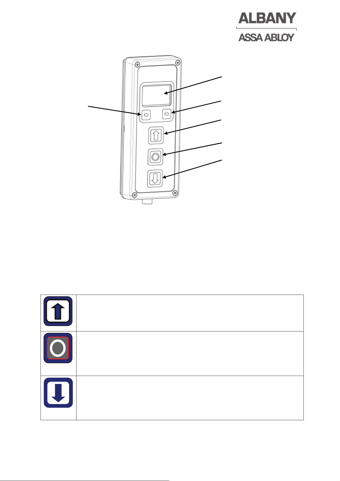
The three buttons “Open (reset)”, “Stop” and “Close” are designed to control the door
and to reset the MCC in the case of a malfunction. They can also be used to alter the
individual settings (e.g. the hold-open time, etc.). The function of the two function
keys is shown on the display at all times.
The display is not mandatory for operating the door. The general function can be
realized through an external 3-pushbutton station.
3.2.1 Use of MCC - Display
The display shows messages, faults, etc. in plain text or graphically. Faults during
normal operation will be indicated immediately (chapter 6.7). For doors without a
display the status light flashes (chapter 6.6).
“Open” button
This button works as an “open” button, sending an opening impulse to
the control system. In addition, this button can be used to scroll upwards
or to increase values in the individual menus.
“Stop” button
The door can be stopped at any point using the “Stop” button.
Simultaneously the door is locked and can only be operated again once
the “Open” or “Close” buttons on the display have been pressed. The
stop function is shown on the display as plain text.
“Close” button
This button sends a closing impulse to the control system. Because the
safeties are checked after every closing impulse there is a short delay
before the closing sequence starts. In addition, this button can be used
to scroll downwards or to decrease values in the individual menus.
Display
Function
key 1 (F1)
Function
key 2 (F2)
Close button
Open button
Stop button
Page 15
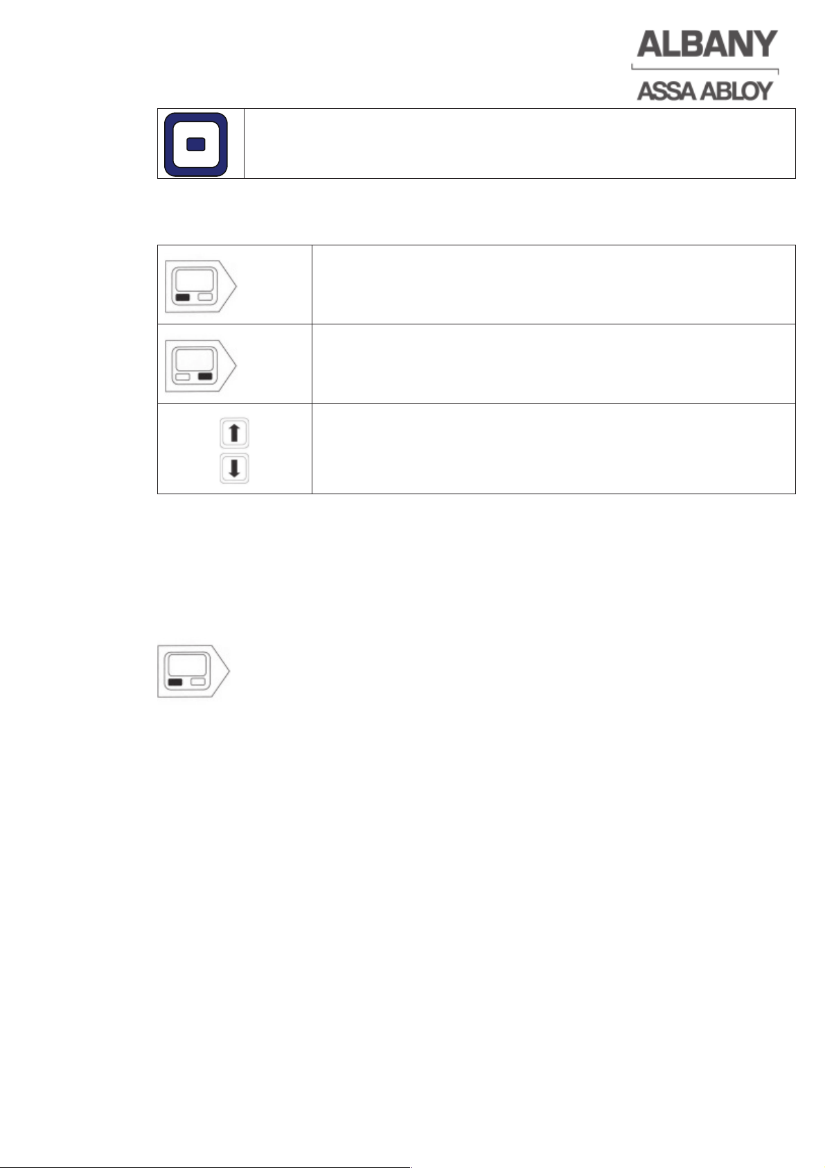
Function keys 1 and 2
The function of these two keys varies and is always shown on the
display immediately above the keys.
The following symbols are used in the instructions to show that the keys should be
pressed.
Press left-hand function key!
Press right-hand function key!
Scroll up or down using the “open” or “close” keys
3.2.2 Save the input
The individual inputs are confirmed by pressing the button “Save”. If several digits
are changed in a view, these must be saved separately.
3.2.3 Exit the input
The input or parameterisation of the MCC control system with the MCC display can
be terminated by pressing (up to three times) the left function key “Escape”:
Alternatively, if no activity occurs, the display returns after a predefined time into the
basic view.
3.2.4 Access codes MCC - Display
The MCC display enables the parameterisation of the MCC. Due to the ability to
change safety-related parameters, the access to the individual parameters is limited
by different levels of access codes. Hereby it is possible that there is no access to
some parameters.
The necessary access code level is shown in brackets in the headers. There are
following options:
No designation => accessible to all
[1] => customer code required (Factory setting 1111)
[2] => installation code required
[3] => system code required
6410R0046_UM_Setup-Operation_MCC_EN11.docx 2012-07-16 15
Page 16
4 Installation
Check the general operation of the door and the safety devices for proper function
after installation of the door.
4.1 Mechanical installation of the control system
The control box should be mounted with the supplied mounting bracket. It can be
also mounted onto an oscillation- and vibration-free wall.
CAUTION
Risk of material damage
Improper installation can cause damage to the wiring.
Ö Ensure that the wiring is routed correctly during the control box installation.
Ö When mounting the motor it must be ensured that the control system is not
hanging on the cables.
Unused entry points should be sealed with appropriate sealed plugs. Any unused
plug-in slots in the junction box must be closed with rubber stoppers. Only cable
fittings with at least IP 55 rating may be used.
4.2 Electrical installation of the control system
4.2.1 Electrical installation requirements
For proper operation of the control unit, the electrical installation must fulfil the
following requirements:
• The electrical work must be carried out according to the applicable local
regulations and requirements.
• An external pre-fuse with 10A - 16A B- or C-characteristic or comparable must be
planned locally for the MCC. The pre-fuse must be selected according to the
conductor cross-sectional area and the selectivity.
Additionally observe the national legal regulations!
• The door must be connected to the potential equalisation of the building.
• An order-specific electrical drawing is included with each door. Wire the control
system according to this electrical drawing.
• If a residual current device (RCD) is used, an AC/DC sensitive short-time delayed
type B RCD is mandatory. Only this type detects AC residual current, pulsating
DC residual current and also smooth DC residual current which could be caused
by the MCC in the event of an error. In most European countries RCDs with a
rated residual current of max. 30 mA are demanded. The use of standard RCDs
(type A) is not permissible.
Additionally observe the national legal regulations.
If you are in any doubt please consult your electrician.
• When connecting the shielded cables (motor, brake and encoder cable) be
ensured that there is good contact between the shield and the metal cable gland.
Otherwise the door could malfunction!
6410R0046_UM_Setup-Operation_MCC_EN11.docx 2012-07-16 16
Page 17
6410R0046_UM_Setup-Operation_MCC_EN11.docx 2012-07-16 17
• The main supply cable must have a cross-sectional area of at least 1.5 mm2 .
Conductors with cross-sectional areas up to 2.5 mm
2
can be connected.
4.2.2 Cross-section wiring / plug-in terminals
Cross-section plug X1, X2, X3, X26 and protective earth terminals:
0.5-2.5 mm
2
without wire end sleeve,
0.5-1.5 mm
2
with wire end sleeve without/with plastic collar to DIN 46228-1/-4
Cross-section plug X4-X21
0.14-1.5 mm
2
without wire end sleeve,
0.14-1.0 mm
2
with wire end sleeve without/with plastic collar to DIN 46228-1/-4
4.2.2.1 Handling recommendation terminal blocks
1. Insert a mini screwdriver (slotted 0.4 x 2.5 mm) in the angular
operating slot up to the stop.
2. The screwdriver blade holds the clamping spring open
automatically so that the conductor can be introduced into the
terminal block.
3. Insert the wire into the terminal block.
4. Withdraw the screwdriver – the conductor is automatically
clamped.
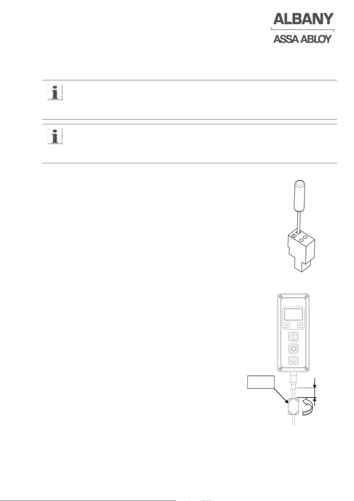
4.2.3 Ferrite at the display cable
For EMC reasons it is required for motor cable length
greater than 2 m that two ferrites are mounted on the
display cable. The Ferrites have to be assembled at
both ends at a distance of approx. 20 mm. The
assembly at the display side is shown exemplarily. The
ferrite are normally pre-assembled or part of the
delivery.
20
Klick!
Page 18
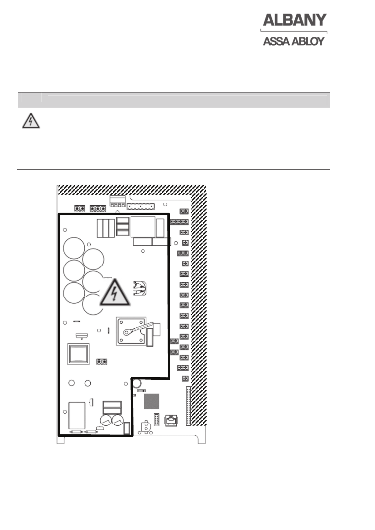
4.3 Wiring restrictions
The wiring must be installed in the hatched area to fulfil the requirements for the
protection class. For wiring which is designed for an insulation test voltage of 3kV,
this restriction is not valid.
DANGER
Risk of electrical shock
Dangerous voltage can apply to low voltage wires / signal wires, which can
lead to an electric shock with serious injuries or death.
Ö Install wires only in hatched area.
Ö Use only wires with an insulation test voltage of 3kV in other areas.
Ö Bundle wires if necessary.
6410R0046_UM_Setup-Operation_MCC_EN11.docx 2012-07-16 18
Page 19
6410R0046_UM_Setup-Operation_MCC_EN11.docx 2012-07-16 19
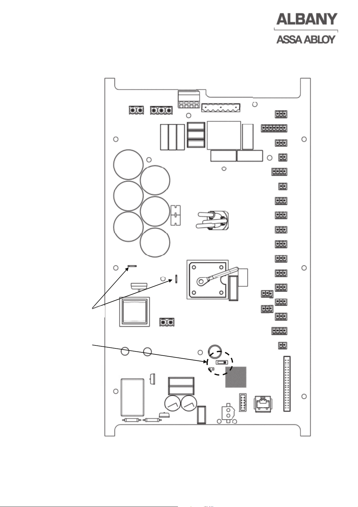
4.4 Terminal assignment of the control system
X4
X5
X6
X71
X7
X8
X9
X10
X11
X12
X13
X14
X15
X17
X19
X20
X21
X23
X22
J6
X26
X16
X18
X3 X2 X1
UPS
PE
X27
Page 20
WARNING
Emergency stop or other external safety-related signals don´t fulfil any safety
requirements if not connected to the terminals X 7 and / or X 71.
Dangerous, not detected failures of the safety devices can occur.
Ö Emergency stop or other external safety-related signals must be connected to the
terminals X 7 and / or X 71.
Ö Observe these points for design and wiring of external safety devices.
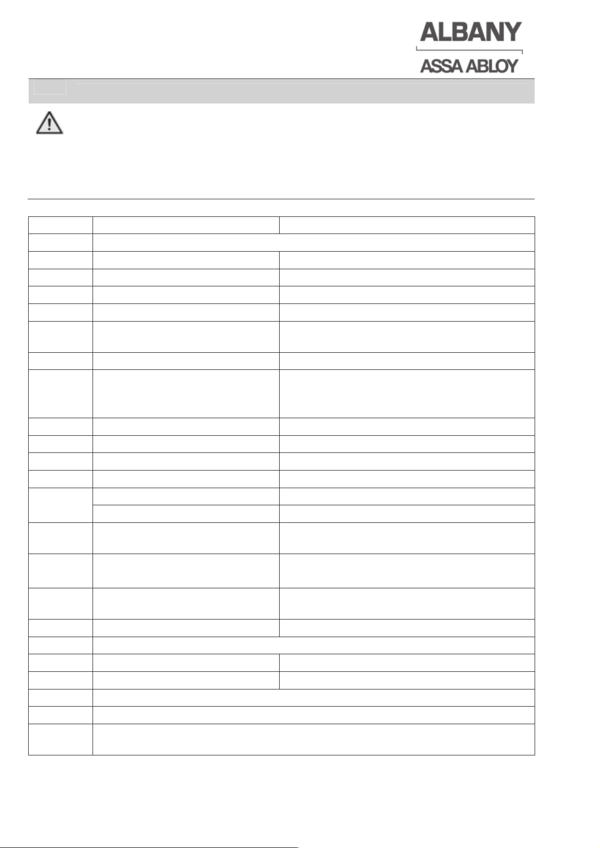
Terminal Function Pin assignment
PE Protective earth connector main voltage and motor cable
X 1 Main power 1=L1, 4=L2, 7=L3
X 2 Motor connection 1=U1, 3=V1, 5=W1
X 3 Brake 1=BN, 3=BU
X 4
Thermal contact
1=24 V DC, 2=Thermal contact, 3= 0 V
X 5 Encoder 1=24V DC, 2=channel A, 3=0V, 4=zero pulse
(not used), 5=24 V DC, 6= channel B, 7=0V
X 6 Reference limit switch 1=24 V DC, 2=reference limit switch, 3= 0 V
X 7 Emergency stop 1/2=emergency stop 1
3/4=emergency stop 2, Emergency hand
crank
X 71 Emergency stop 1/2=emergency stop 3
X 8 Emergency manual lever
X 9 Receiver, door line photocell 1= 24 V DC, 2=photocell, 3= 0 V
X 10 Transmitter, door line photocell 1= 24 V DC, 2=not used, 3= 0 V
X 11 Safety edge 8,2 kȍ 2/3=8,2 kȍ
Receiver, pre-running photocell 1= 24 V DC, 2=photocell, 3= 0 V
X 12 Transmitter pre-running
photocell
1= 24 V DC, 2=photocell, 3= 0 V
X12-X19 General I/O 1=24 V DC or Output
2=Input, 3=0V
X 20 3-pushbutton station (doors
without display)
1=24 V DC, 2=open, 3=stop, 4=close
X 21 Status light 1=0 V, 2=24 V DC
X 22 Modbus interface for display and other operating controls and auxiliary modules
X 23 M8-junction box
X 26 Break resistor 1/3=180 ȍ
X 27 Clone function
UPS Connection UPS unit
J 6
Switch for emergency lever/emergency hand crank contact selection (chapter
4.5)
6410R0046_UM_Setup-Operation_MCC_EN11.docx 2012-07-16 20
Page 21
6410R0046_UM_Setup-Operation_MCC_EN11.docx 2012-07-16 21
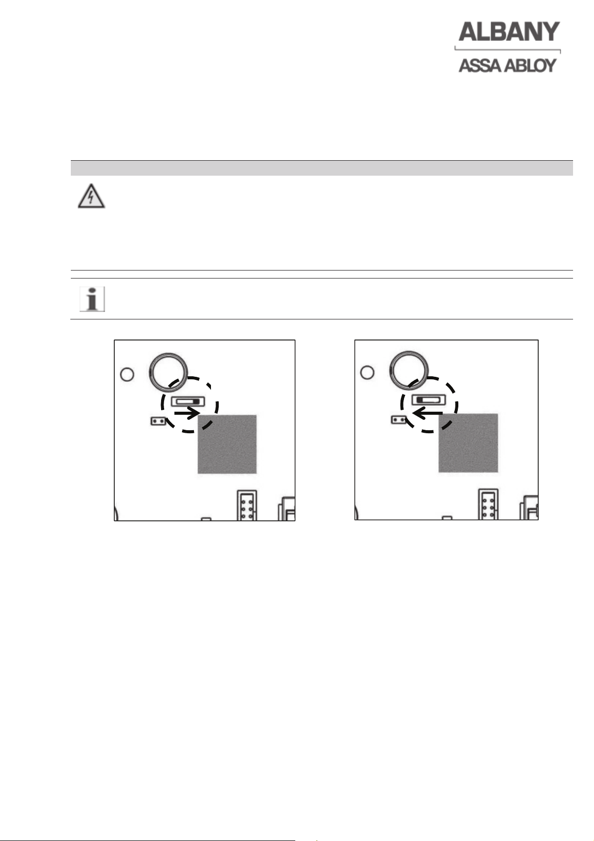
4.5 Emergency manual lever / emergency hand crank contact selection
By changing over the switch (while the MCC is switched off) on the main board you
can select whether the emergency manual lever or the emergency hand crank
(depending on the door type, details in electrical drawing) is controlled by a normally
open or normally closed contact.
DANGER
Risk of electrical shock
Dangerous touch voltage applies at the control system up to 30 seconds after
turning off/disconnecting the supply voltage.
Ö Wait 30 seconds for discharging the capacitors before working at electrical parts
and wiring.
Ö Do not touch other than the described components on the board.
The selection will normally be done at the Albany Door Systems production.
Adjustments are only necessary for replacement units.
NC contact NO contact
4.6 Reference limit switch
All Albany Door System Doors are supplied with a reference limit switch mounted in
the upper end position. This reference limit switch indicates the zero (reference) point
for door positioning via the encoder. There are 2 types of reference limit switches:
• Mechanical spindle or cam reference limit switch. This type of limit switch must be
set to the upper end position mechanically during installation (see also Assembly
Instructions for the door).
• Inductive reference limit switches. This type of limit switch does not need to be set
during installation.
J6 J6
Page 22
4.7 Setting door limits
Set the end positions before using the door. There are two types to teach-in.
WARNING
Risk of material damage
If the door is moved beyond the lower end position manually during installation
(in hold to run mode), this may result in severe damage to the door.
Ö Observe the door during setting the end positions permanently.
While setting the door limits the door will only move in creep mode in hold to run
mode.
4.7.1 Setting door limits for doors without displays
The status light (optional in doors without a display) flashes very fast throughout the
entire setup process. This means that no error messages or service information is
shown during installation.
To set the final door positions the open and stop buttons on the pushbutton station
must be pressed together for approximately 10 seconds. After this the status light will
start flashing. The flash codes show which setting must be carried out next.
Flash code Meaning
2 fast flashes Set the lower end position
3 fast flashes Set the upper end position (on the reference limit switch)
4 fast flashes Set the hold-open time
When the appropriate end position has been reached this is confirmed using the stop
button on the pushbutton station. After saving the upper end position the hold-open
time (4 flashes) can be set. For this wait for as long as the door should remain open
in future and then press the close button to save this.
Example:
Hold-open time = 6 seconds => after saving the upper end position (the status light
will flash fast 4 times) wait for 6 seconds and then press the “close” button. If the
close button is pressed within 2 seconds the hold-open time is switched off.
4.7.2 Setting door limits for doors with displays
The control is delivered without the limit positions set; therefore this view will be the
first that appears when the control system is powered up. It is also possible to set the
door limit positions by pressing the open and stop buttons on the keypad together for
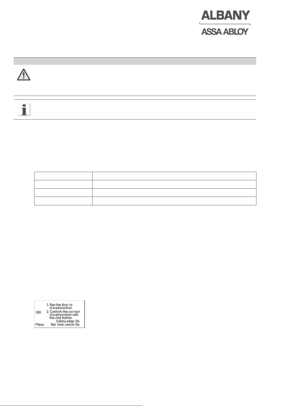
approximately 10 seconds. The following message will then appear:
In this view the setup cannot be restarted again through simultaneous pressing of the
Open and Stop button. For renewed activation of the setup, press the Stop
pushbutton and then restart the setup by simultaneously pressing the Open and Stop
button or by switching the Main switch off and back on again.
6410R0046_UM_Setup-Operation_MCC_EN11.docx 2012-07-16 22
Page 23
6410R0046_UM_Setup-Operation_MCC_EN11.docx 2012-07-16 23
The Menu button can be used to quit the setup at this point to check or change the
default settings (e.g. brake voltage).
Now use the keypad to move the door to the lower final position and save this by
pressing the stop button on the keypad (If the door is already in the closed position,
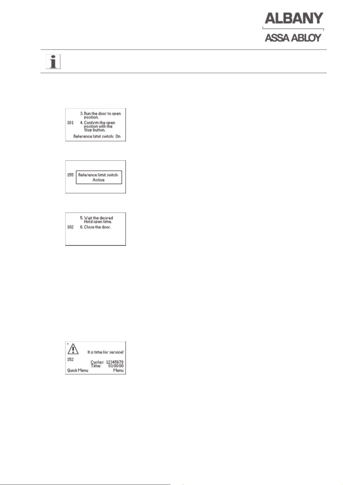
the position can be saved without moving the door.). The following message will then
appear automatically.
For doors with a reference limit switch, use the keypad to move the door to the upper
end position until it stops automatically. The following message will then appear:
Save the upper end position by pressing the stop button on the keypad. The following
message will then appear automatically.
(Be ready for this step it starts once the top position is set!)
The hold-open time can now be set. For this wait for as long as the door should
remain open in future. To save this press the “close” button on the keypad.
Example:
Hold-open time = 6 seconds => after saving the upper end position wait for 6
seconds and then press the “close” button. If the close button is pressed within 2
seconds the hold-open time is switched off. Instead of the Close button, it is also
possible to deactivate automatic closing (hold open time =0) by pressing the Open
button. Changing the hold-open time (chapter 4.10)
After the 1st setup the service counter must be reset (chapter 4.33), otherwise the
following message appears after several cycles.
This resetting can be omitted in subsequent end position programming.
Page 24
6410R0046_UM_Setup-Operation_MCC_EN11.docx 2012-07-16 24
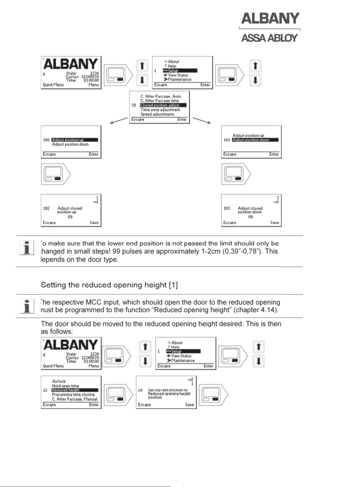
4.8 Correcting the lower end position [1]
To make sure that the lower end position is not passed the limit should only be
changed in small steps! 99 pulses are approximately 1-2cm (0,39”-0,78”). This
depends on the door type.
4.9 Setting the reduced opening height [1]
The respective MCC input, which should open the door to the reduced opening height,
must be programmed to the function “Reduced opening height” (chapter 4.14).
The door should be moved to the reduced opening height desired. This is then saved
as follows:
The reduced opening height is only used for inputs with the appropriately
programmed function!
Page 25
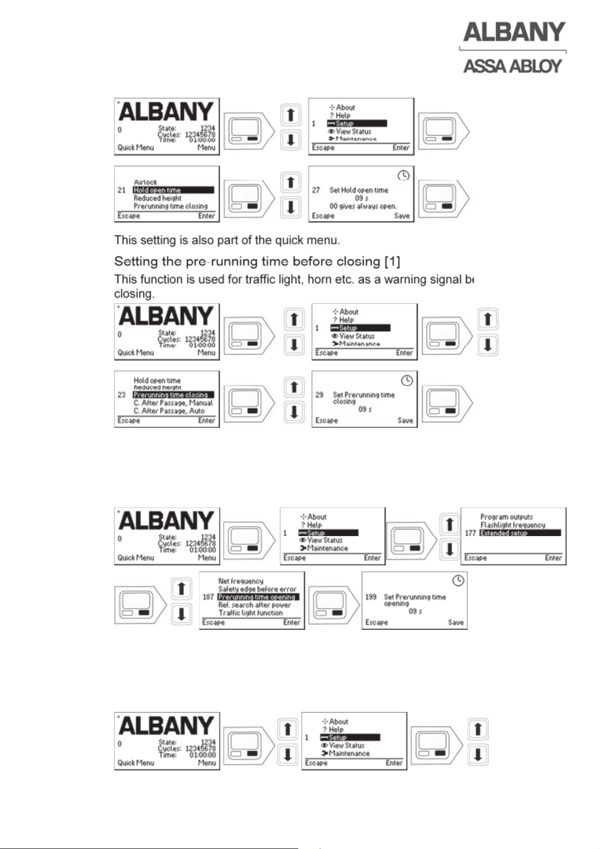
4.10 Setting the hold-open time [1]
This setting is also part of the quick menu.
4.11 Setting the pre-running time before closing [1]
This function is used for traffic light, horn etc. as a warning signal before the door is
closing.
This setting is also part of the quick menu.
4.12 Setting the pre-running time before opening [1]
When this pre-running time is activated there will be a delay before the door opens (it
opens after the pre-running time).
4.13 Close after passage function
4.13.1 Setting the close after passage function without hold-open time [1]
This setting is used to set the close after passage function at actuator inputs with the
function “Open command without automatic close function”.
6410R0046_UM_Setup-Operation_MCC_EN11.docx 2012-07-16 25
Page 26
6410R0046_UM_Setup-Operation_MCC_EN11.docx 2012-07-16 26
4.13.2 Setting the close after passage function with hold-open time [1]
This setting is used to set the close after passage function at actuator inputs with the
function “Open command with closing after time”.
4.13.3 Setting the close after passage time [1]
4.14 Programming the inputs [1]
Select the input to be programmed (observe the electrical drawing) and enter one of
the function codes listed below.
For safety reasons inputs 1 and 2 (X12 and X13) can only be re-programmed with
system code [3] by the Albany Door Systems Service Team.
For traffic lights with recognition of direction it is important that the impulse activators
are assigned to the direction. The front is always the side of the door where the
display/ control panel is mounted. If direction dependant traffic lights are not used
only “front” opening functions shall be used on both sides of the door.
Page 27
6410R0046_UM_Setup-Operation_MCC_EN11.docx 2012-07-16 27
The options are as follows:
Code No
Function
41 Open command with closure after a time (front)
42 Open command with closure after a time (back)
43 Open command (reduced opening height) without automatic closing
function
44 Open command (reduced opening height) with automatic closing function
(front)
75 Open command (reduced opening height) with automatic closing function
(back)
22 Input without function (e.g. deactivating actuators)
23 Open command (normally open) without automatic closing function
24 Close command (normally open)
25 Stop command (normally closed) => Use Input X7/X71 for emergency
stop!
26 Toggle circuit
69 Additional safety (normally closed)
51 Additional safety (normally open)
53 Interlock input (normally closed)
80 Interlock input (normally open)
60 Interlock (switch on/off)
56 Lock door, e.g. mech. door locking, pass door, etc. (normally closed)
54 Crash (normally closed) (function only possible on X12 and X13!)
57 Long vehicle input for airlock (normally open)
45 Middle actuator input for airlock (normally open)
58 Permanent opening display
59 External permanent opening
91 PLC Input 1
92 PLC Input 2
93 PLC Input 3
94 PLC Input 4
95 PLC Input 5
96 PLC Input 6
97 PLC Input 7
98 PLC Input 8
62 Open command (normally closed contact) without automatic close function
71 Breakaway (NC contact) (only for US-market)
67 Input battery signal safety edge – radio system
Page 28
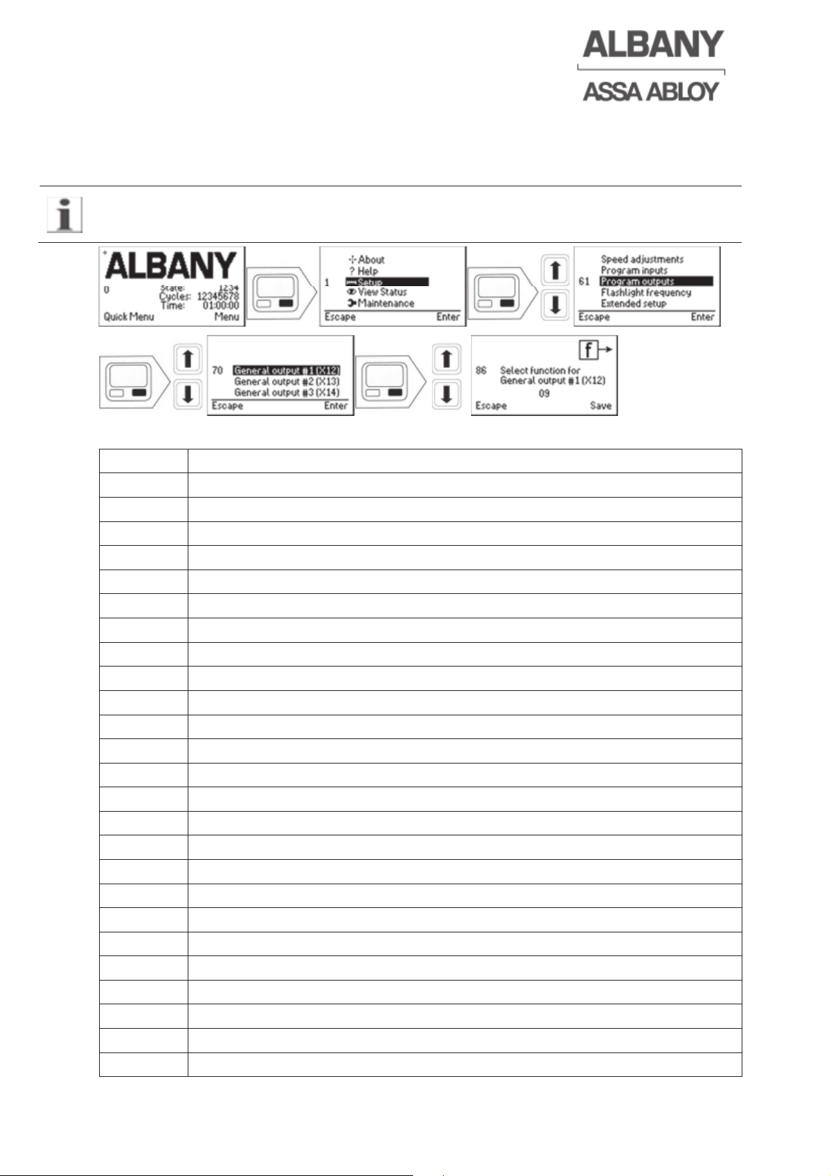
4.15 Programming the outputs [1]
Select the output to be programmed (electrical drawing) and enter one of the function
codes listed below.
For safety reasons outputs 1 and 2 (X12 and X13) can only be re-programmed with
system code [3] by the Albany Door Systems Service Team.
The options are as follows:
Code No Function
65 +24 V DC (continuous voltage)
28 Traffic light (red/green), front (activation relay)
29 Traffic light (red/green), back (activation relay)
30 Switch traffic light on/off with door closed
76 Traffic light green 24 V DC front
77 Traffic light green 24 V DC back
78 Traffic light red 24 V DC front
79 Traffic light red 24 V DC back
22 Output without function (e.g. deactivating activators)
31 Flashlights
33 Interlock
34 Door open
35 Door closed
36 Door ready for work
81 Malfunction indication
37 Status light
38 Pre-running photocell transmitter
40 Additional security
83 PLC output 1
84 PLC output 2
85 PLC output 3
86 PLC output 4
87 PLC output 5
88 PLC output 6
89 PLC output 7
6410R0046_UM_Setup-Operation_MCC_EN11.docx 2012-07-16 28
Page 29
6410R0046_UM_Setup-Operation_MCC_EN11.docx 2012-07-16 29
90 PLC output 8
72 UPS On/Off control system
4.16 Airlock function [1]
4.16.1 Airlock wiring
A 3-wire connecting cable is required for the airlock wiring between Door A and B.
Two 8,2k resistors are also necessary. The airlock connection of both MCC´s is
only possible at the terminals X14!
The following connections are to be provided (Observe electrical drawing of the
door!):
The door with the middle actuator (WSB) is always Door A! The free inputs X1213, X15-19 can be used.
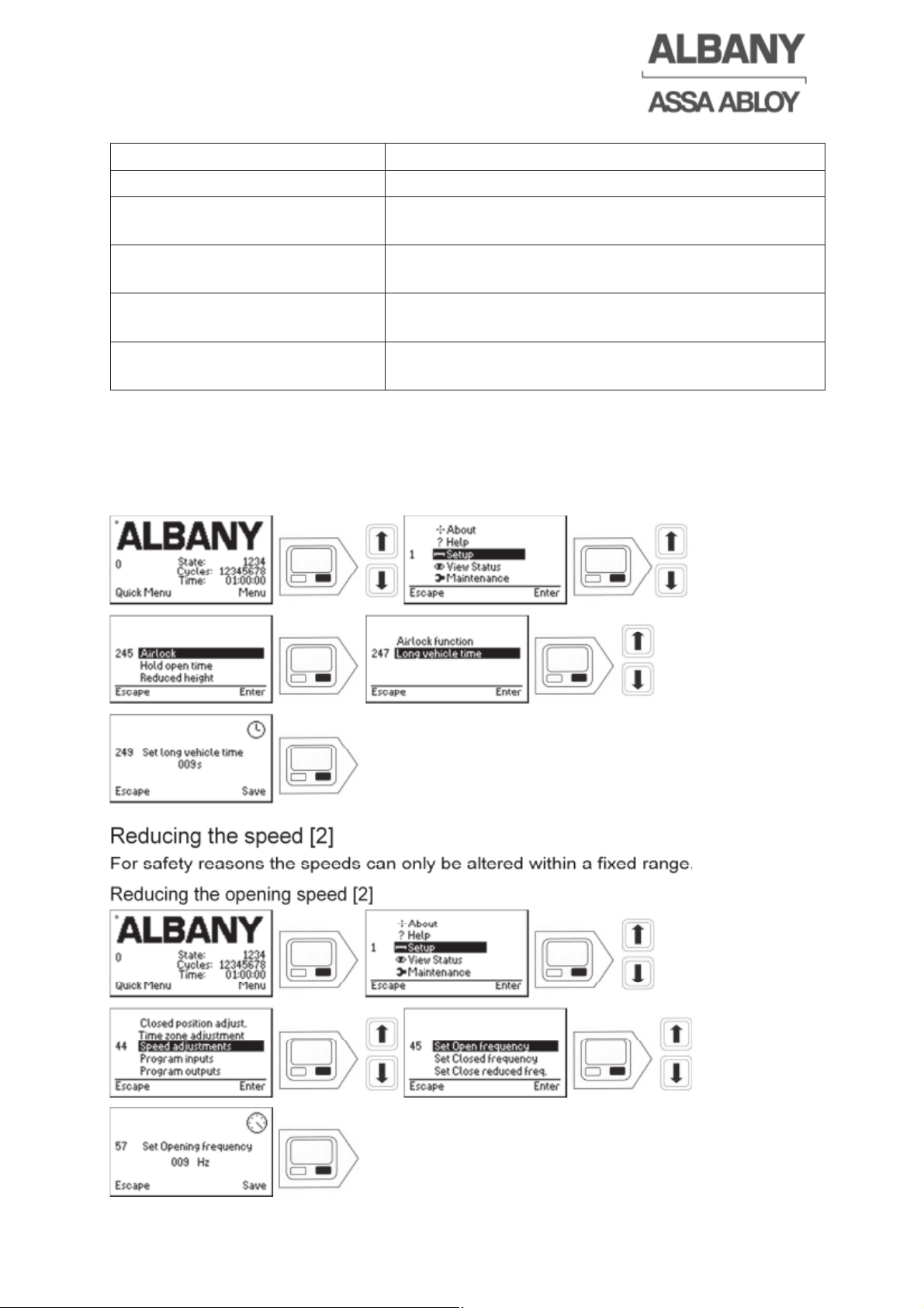
4.16.2 Setting the airlock function [1]
The functions of the X14 input must be programmed to code number 22 (input
without function). The output X14 must be programmed to code number 65 (24 V
continuous voltage).
The close after passage time can at wish be activated for actuator with hold open
time and for actuators without hold open time (chapter 4.13.1 / 4.13.2).
In this menu item it is possible to select whether a single door, Door A or B of the
airlock is concerned and whether the airlock is operated with or without middle
actuator.
MCC Door B
MCC Door A
X14.1
X14.2
X14.3
X14.1
X14.2
X14.3
WSB
8.2k
8.2k
Page 30
6410R0046_UM_Setup-Operation_MCC_EN11.docx 2012-07-16 30
The selection options are:
Function Description
Single door No airlock operation
Airlock with middle actuator
Door A
Airlock operation with middle actuator Door A
Airlock with middle actuator
Door B
Airlock operation with middle actuator Door B
Airlock without middle actuator
Door A
Airlock operation without middle actuator door (A)
Airlock without middle actuator
Door B
Airlock operation without middle actuator door (B)
4.16.3 Setting the long vehicle time [1]
The long vehicle time is the time which the door line photocell in the side frame and
the middle actuator have to be simultaneously activated to start the long vehicle
function. With the long vehicle function both doors open irrespective of the airlock
sequence. The factory setting is 15 s.
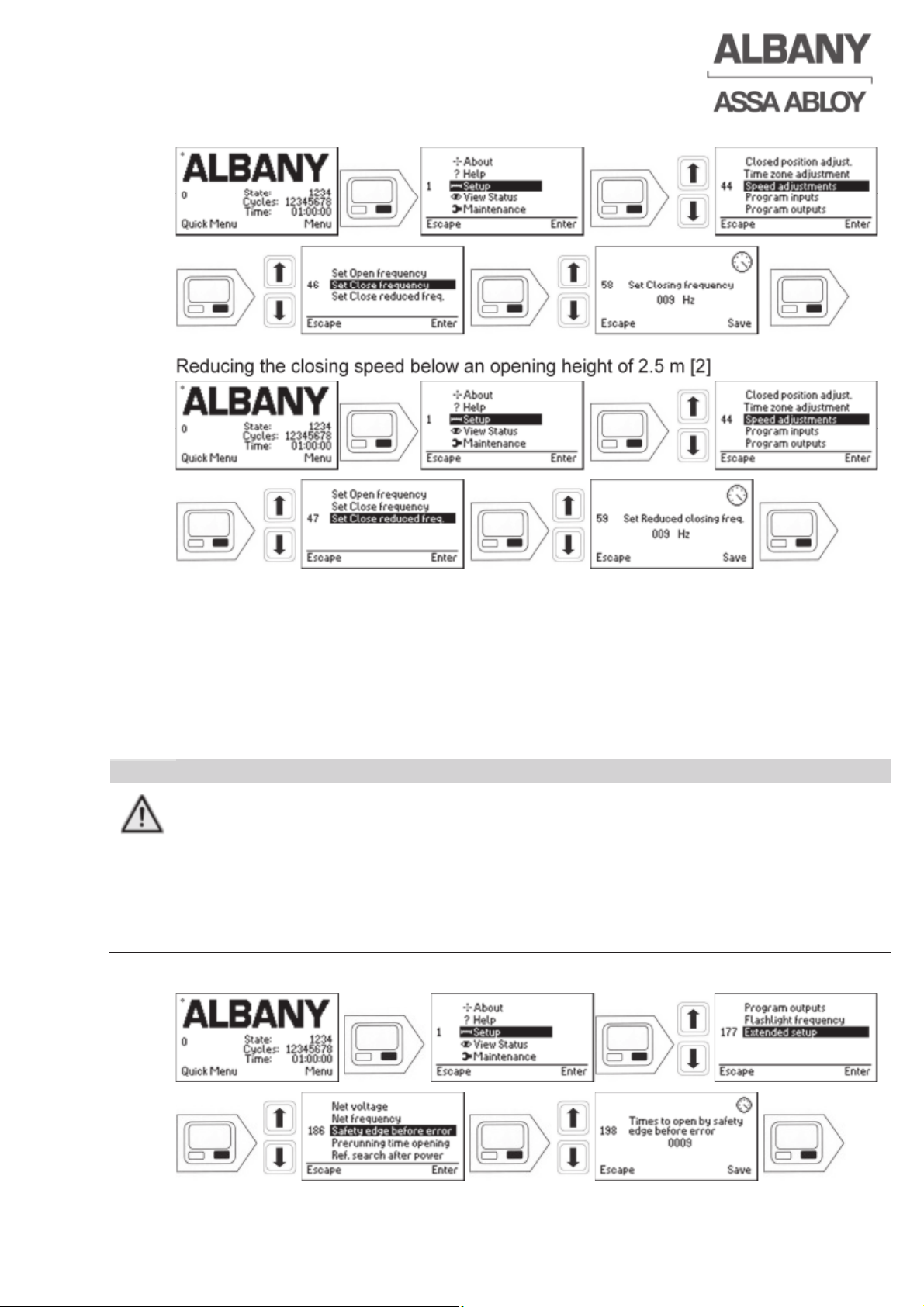
4.17 Reducing the speed [2]
For safety reasons the speeds can only be altered within a fixed range.
4.17.1 Reducing the opening speed [2]
Page 31
6410R0046_UM_Setup-Operation_MCC_EN11.docx 2012-07-16 31
4.17.2 Reducing the closing speed above an opening height of 2.5 m [2]
4.17.3 Reducing the closing speed below an opening height of 2.5 m [2]
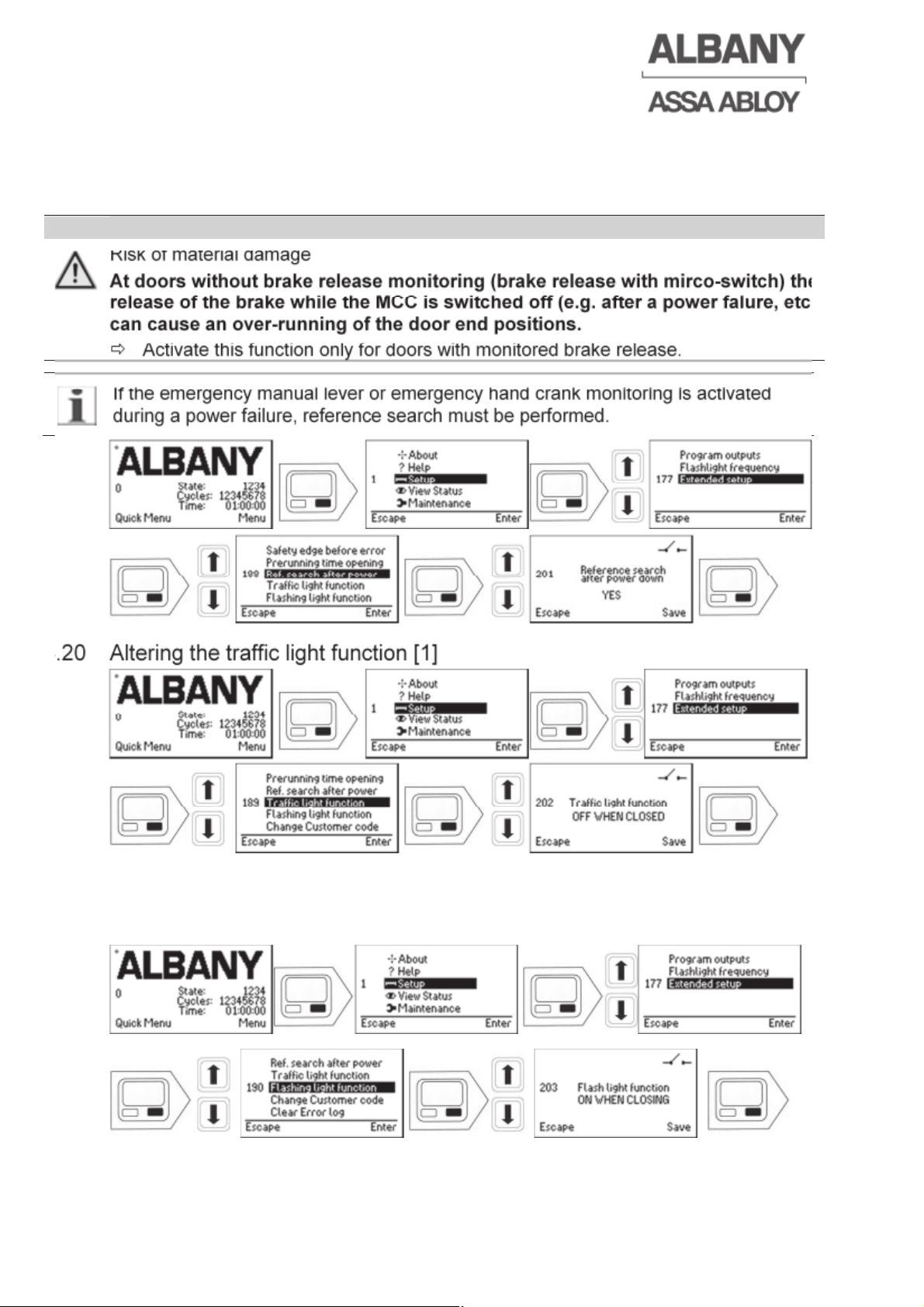
4.18 Adjustment of activations of the safety edge or pre running photocell [2]
The electrical safety edge serves as closing edge protection. As standard, the door is
usually locked in the upper end position after the electrical safety edge has activated
once. Using this menu the value can be increased, for example to twice. This means
that the door would only lock in the upper end position after two activations of the
electrical safety edge (without the door closing completely). For the pre-running
photocell this value is set to 10 activations as standard.
WARNING
Personal risk at the door is increased
A collision with the door curtain can be repeatedly performed with increasing
the value
Ö The value should only be altered by our service team in reasoned, exceptional
cases.
Ö For safety reasons the value for the electrical safety edge should only be
increased to a maximum of 3 activations!
Page 32
6410R0046_UM_Setup-Operation_MCC_EN11.docx 2012-07-16 32
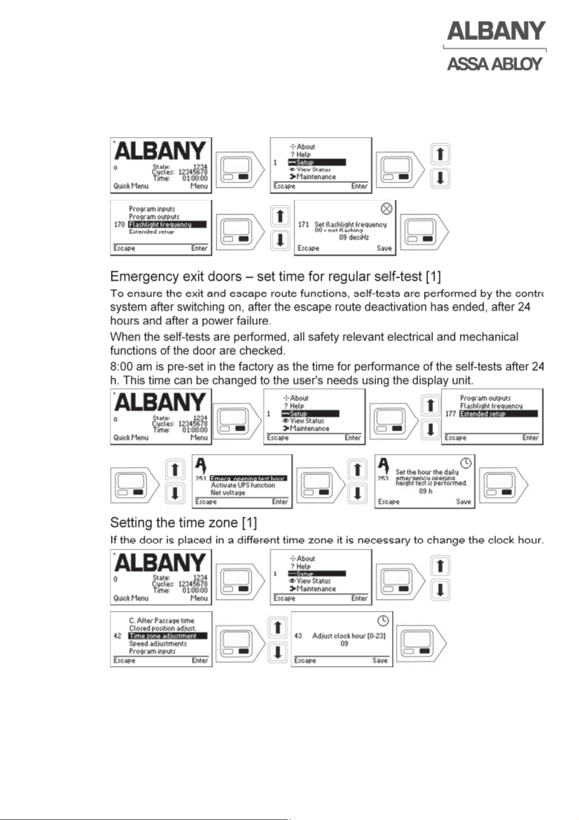
4.19 Activating reference search after a power failure [2]
Here it can be select whether a reference search must be performed after a power
failure. This monitoring is intended to last for around 5-6 hours without power.
Afterwards the reference search must be performed.
WARNING
Risk of material damage
At doors without brake release monitoring (brake release with mirco-switch) the
release of the brake while the MCC is switched off (e.g. after a power falure, etc.)
can cause an over-running of the door end positions.
Ö Activate this function only for doors with monitored brake release.
If the emergency manual lever or emergency hand crank monitoring is activated
during a power failure, reference search must be performed.
4.20 Altering the traffic light function [1]
Here it can be selected whether the traffic light remains on all the time or switched off
when the door is closed.
4.21 Altering the flashing light function [1]
Here it can be selected whether the flashing light is on whenever the door moves or
only during closing.
Page 33
6410R0046_UM_Setup-Operation_MCC_EN11.docx 2012-07-16 33
4.22 Setting the flash rate of the flashlight [1]
The control system offers the option of using a normal indicator light as a flashlight.
For this the switching frequency of the flashlight output can be changed using the
following menu option.
4.23 Emergency exit doors – set time for regular self-test [1]
To ensure the exit and escape route functions, self-tests are performed by the control
system after switching on, after the escape route deactivation has ended, after 24
hours and after a power failure.
When the self-tests are performed, all safety relevant electrical and mechanical
functions of the door are checked.
8:00 am is pre-set in the factory as the time for performance of the self-tests after 24
h. This time can be changed to the user's needs using the display unit.
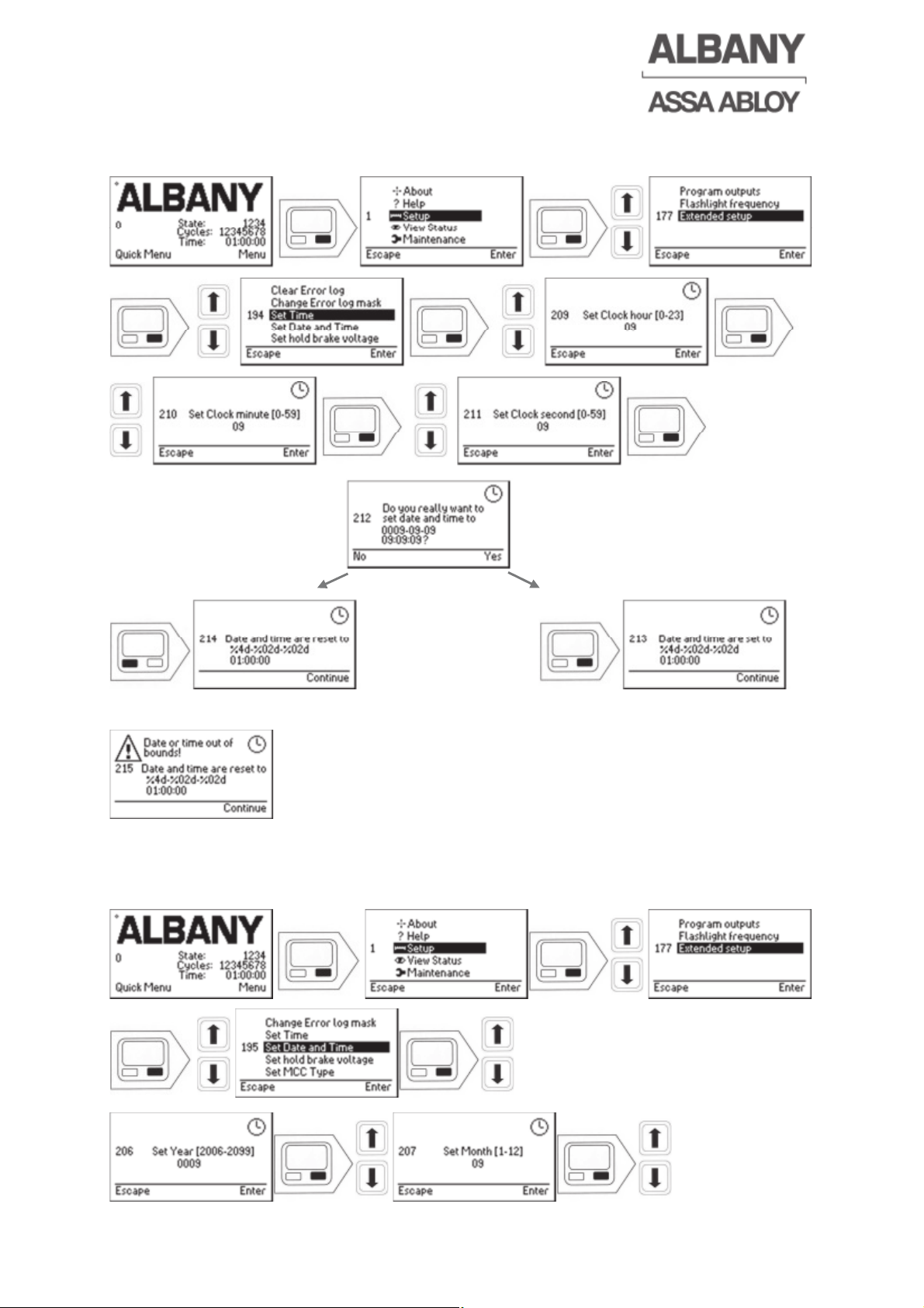
4.24 Setting the time zone [1]
If the door is placed in a different time zone it is necessary to change the clock hour.
Page 34
6410R0046_UM_Setup-Operation_MCC_EN11.docx 2012-07-16 34
4.25 Setting of the time [1]
If the clock setting is not correct, it is necessary to change the time.
If the adjusted values are not valid following view will be shown.
Date and time will be set to the old values.
4.26 Setting of the date and time [2]
Here the control system date and clock can be corrected.
Page 35
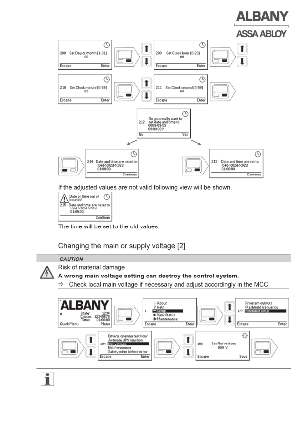
If the adjusted values are not valid following view will be shown.
The time will be set to the old values.
4.27 Changing the main or supply voltage [2]
CAUTION
Risk of material damage
A wrong main voltage setting can destroy the control system.
Ö Check local main voltage if necessary and adjust accordingly in the MCC.
The control system must be switched off and on again, so that the main voltage
change becomes effective.
6410R0046_UM_Setup-Operation_MCC_EN11.docx 2012-07-16 35
Page 36
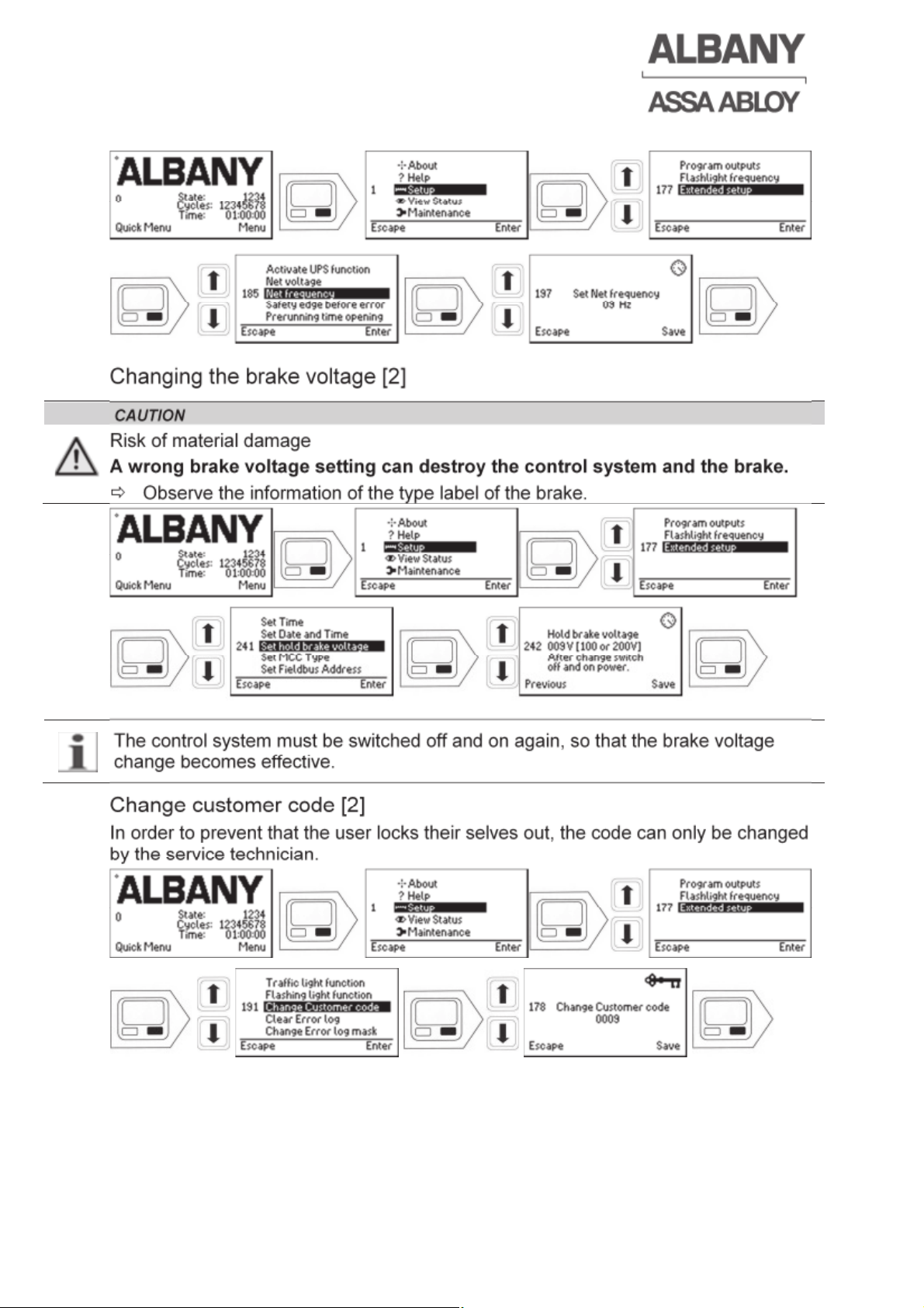
4.28 Changing the main supply voltage frequency [2]
4.29 Changing the brake voltage [2]
CAUTION
Risk of material damage
A wrong brake voltage setting can destroy the control system and the brake.
Ö Observe the information of the type label of the brake.
The control system must be switched off and on again, so that the brake voltage
change becomes effective.
4.30 Change customer code [2]
In order to prevent that the user locks their selves out, the code can only be changed
by the service technician.
6410R0046_UM_Setup-Operation_MCC_EN11.docx 2012-07-16 36
Page 37
6410R0046_UM_Setup-Operation_MCC_EN11.docx 2012-07-16 37
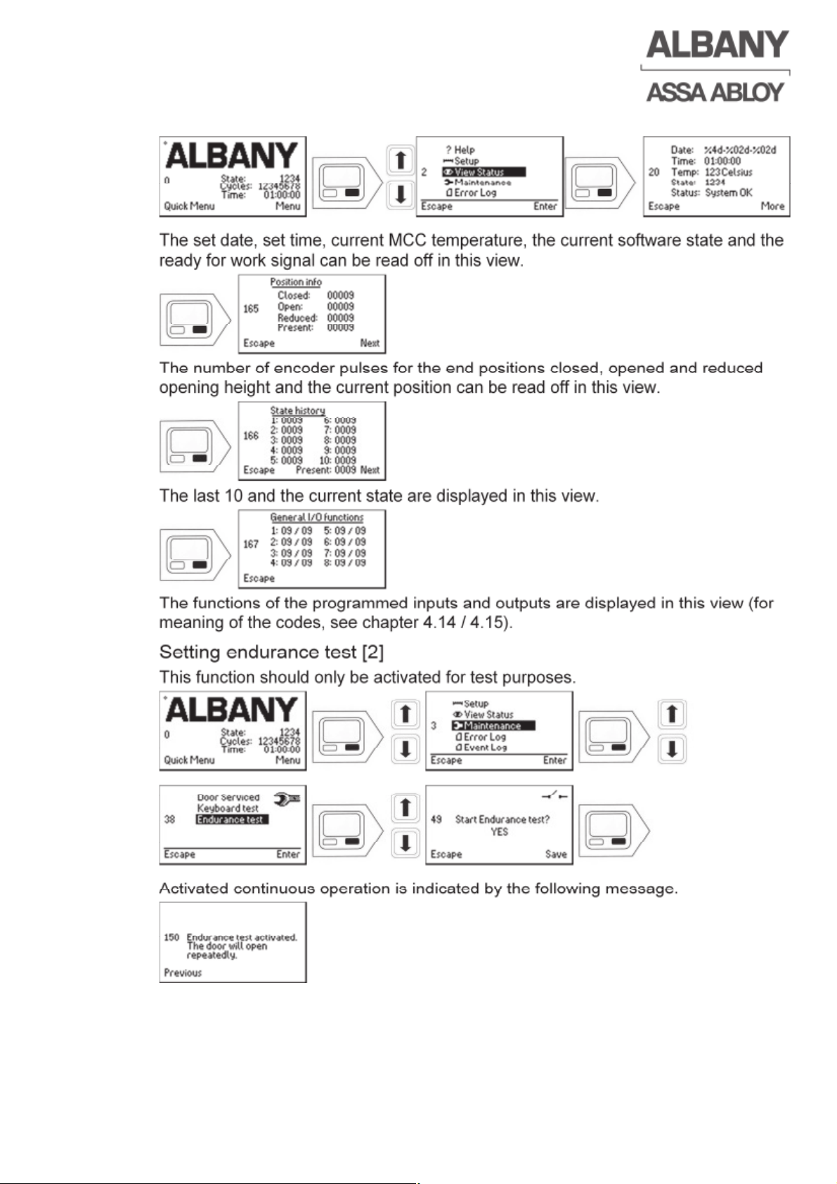
4.31 Querying the door positions and the state history [0]
The set date, set time, current MCC temperature, the current software state and the
ready for work signal can be read off in this view.
The number of encoder pulses for the end positions closed, opened and reduced
opening height and the current position can be read off in this view.
The last 10 and the current state are displayed in this view.
The functions of the programmed inputs and outputs are displayed in this view (for
meaning of the codes, see chapter 4.14 / 4.15).
4.32 Setting endurance test [2]
This function should only be activated for test purposes.
Activated continuous operation is indicated by the following message.
Deactivation is performed in the same order!
Page 38
6410R0046_UM_Setup-Operation_MCC_EN11.docx 2012-07-16 38
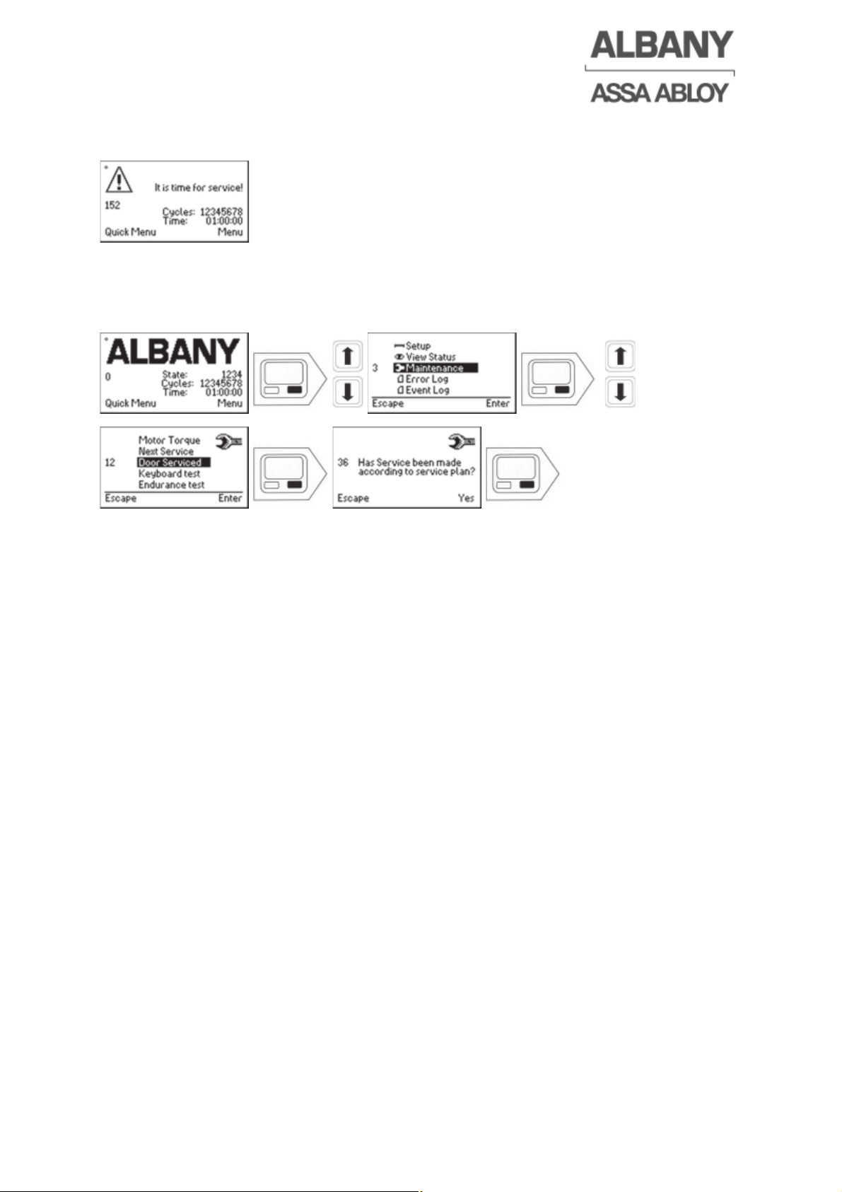
4.33 Reset service interval [1]
If service is due, it is automatically shown with the following message.
Every service interval indicated is recorded in the event log.
If the service has been carried out in accordance with Albany Door Systems
specifications the service interval counter must be reset. Every time the service
interval counter is reset this is recorded in the event log.
Page 39
6410R0046_UM_Setup-Operation_MCC_EN11.docx 2012-07-16 39
5 Operation
5.1 Safety instructions
Observe the safety instructions in Section 2 and the safety instructions in the user
guide for the door.
5.2 Display
The display shows messages, faults, etc. in plain text or graphically. During operation
the time, cycle counter and status information are shown.
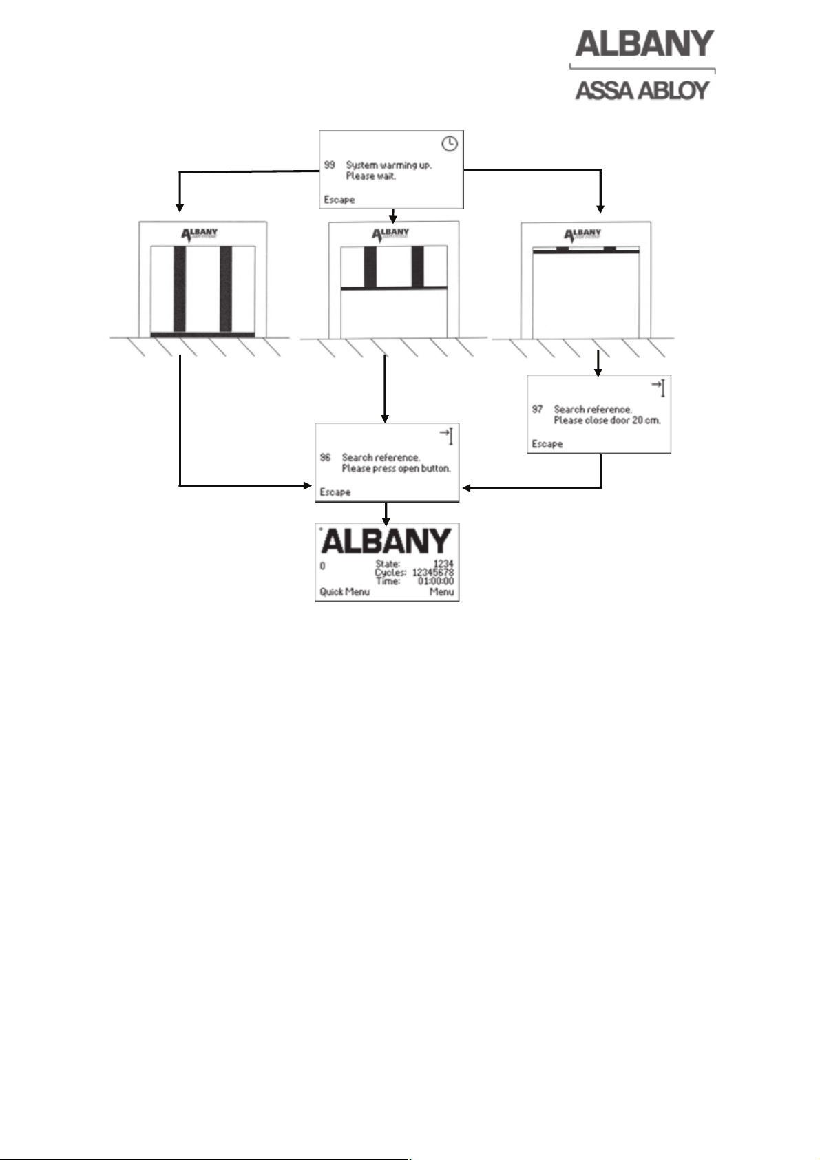
5.3 Switch-on and reference run
The position of the door and the vector control of the motor are regulated by an
incremental encoder. This encoder is firmly mounted on the motor. A reference
search is therefore necessary when the system is switched on for the first time. If for
doors with brake release monitoring (normally doors with emergency manual lever)
the control system is switched off after the reference search, a renewed reference
search is only necessary if the emergency manual lever has been used (alteration of
the door position).
This monitoring is intended to last for around 5-6 hours without power. Afterwards the
reference search must be performed. Refer to the following flow diagram for this. A
reference search is always necessary for doors without brake release monitoring
(normally for doors with hand crank).
Observe the information and setting options for this function in chapter 4.19.
The reference search is initiated automatically by pressing the “Open” pushbutton
or from external actuators (e. g. motion detector).
If the main switch is switched on, and if the emergency manual lever has not been
activated since the door was last switched off (maximum 5-6 hours) a reference
search does not need to be performed. After an open or close command the door will
run in standard operating mode.
If the emergency manual lever has been used, or the maximum monitoring time of
the emergency manual lever has been exceeded a reference search must be
performed.
Page 40
6410R0046_UM_Setup-Operation_MCC_EN11.docx 2012-07-16 40
The door is now ready for operation.
5.4 Opening the door
An “open” impulse is given by any impulse activator or from the keypad. The brake is
released; the drive motor is activated by the MCC with a pre-defined acceleration
ramp. The door opens with maximum speed until it reaches the starting point of the
upper deceleration ramp. The door is now decelerated by the frequency converter
and stopped in the adjusted upper end position. When this position is reached the
motor is switched off and the brake is activated.
Depending on the function, which has been pre-selected, either the hold-open or
close after passage time is started or the control system waits for a closing impulse.
5.5 Closing the door
Once the end of the hold-open time or close after passage time is reached or a
closing impulse is received all connected safety devices are first tested by the control
system. If this safety test is successful the safety devices are activated, the brake is
released and the motor is driven by the frequency converter with a pre-defined
acceleration ramp. The door closes as far as the starting point of the lower
deceleration ramp. The door is now decelerated with a pre-defined deceleration ramp
and stops in the lower end position. When this position is reached the motor is
switched off and the brake is activated.
Page 41
6410R0046_UM_Setup-Operation_MCC_EN11.docx 2012-07-16 41
The safety devices are switched off max. 50 mm (2”) before the lower end position is
reached. This prevents the door from reversing when it reaches the ground.
5.6 Stop the door
The door can be stopped in any position by pressing the “Stop” button. An “Open” or
“Close” impulse then starts the door’s operation again. If the stop button on the
display unit is pressed it is necessary to press the display open or close button to
start the door. The control system will also remember that it is stopped with the
display stop button if it is restarted by switching on and off the main supply, also in
this case only the display open or close button can start the door again.
5.7 Power failure
If a power failure occurs doors with power off brake immediately stops wherever it is
at that moment. Once the main power returns the door will only be in normal
operation after a renewed impulse.
Doors with power on brake open or close automatically in the event of power failure
depending on the spring balancing and door position. A closed door will open and an
open door can close slightly (depending on the spring balancing).
5.8 Emergency manual operation
If there is a power failure or repair work or maintenance is being carried out it may be
necessary to open the door manually.
Doors with power on brake do not have an emergency manual lever!
WARNING
The door may partially open or close by itself after the emergency manual lever has
been activated!
There is the risk of injuries by the movement of the door curtain.
Ö Observe the door during use of the emergency manual lever permanently.
WARNING
Risk of injury
It can lead to injuries by simultaneous starting of the motor during inserting the
emergency hand crank.
Ö Always switch off the main switch before using the emergency hand crank.
By using the emergency manual lever on the side frame the brake of the drive motor
can be released via a disengagement cable. Depending on the balancing system and
the door position the door curtain may partially open or close by itself. Now it is
possible to reach below the bottom rubber in the middle of the door and push the
door curtain up. While doing this the door curtain will wind onto the top roll. To get
back to the normal operation of the door the emergency manual lever should be
returned to its original position. The control system can then be switched on and the
door can be operated normally.
At doors with emergency hand crank, the door can be opened and closed by turning
the emergency hand crank which must be inserted on the bottom of the motor.
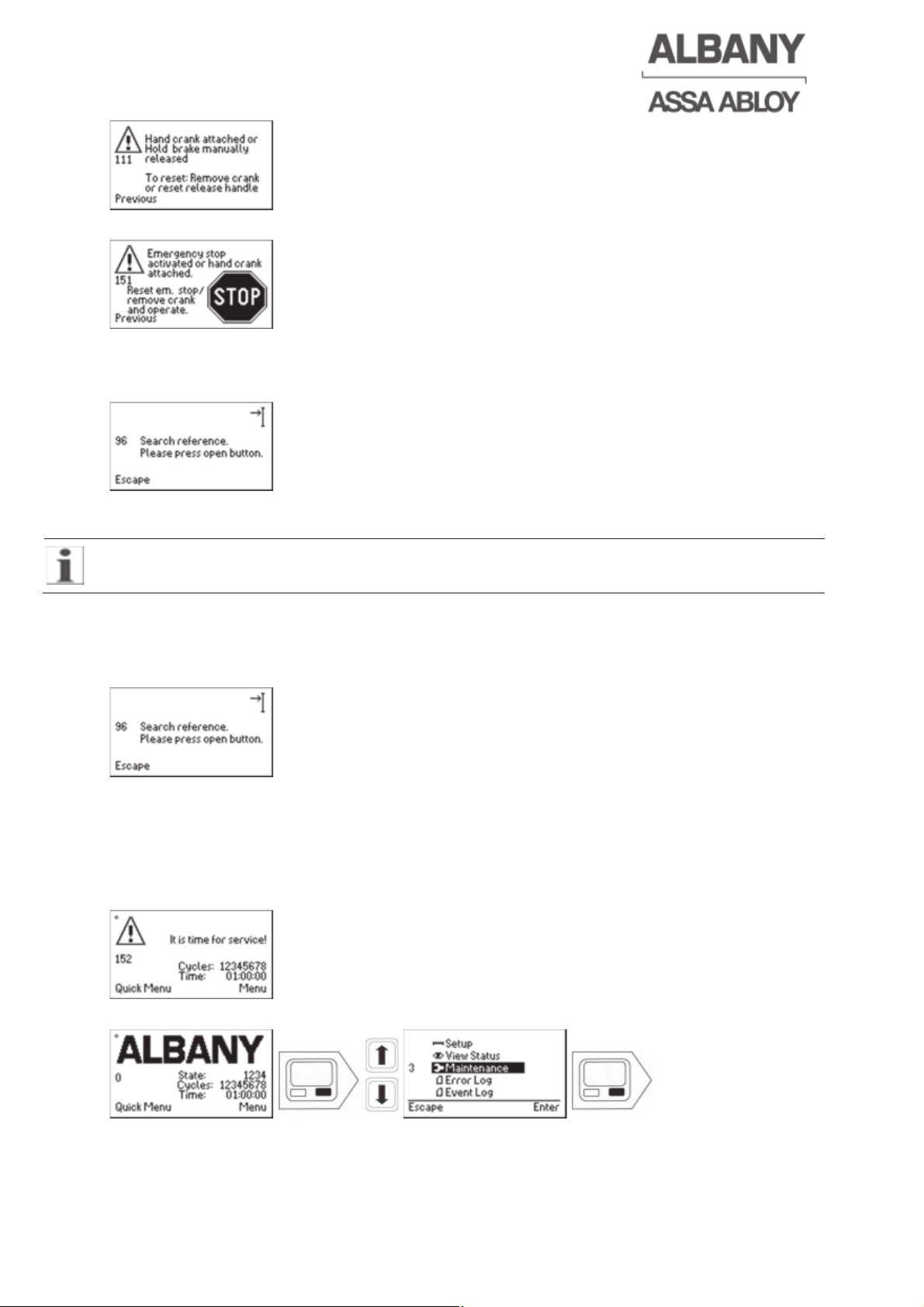
If the emergency manual lever is still operated when the main switch is switched on
the following message appears.
Page 42
6410R0046_UM_Setup-Operation_MCC_EN11.docx 2012-07-16 42
The following message appears for doors with emergency hand crank
This message is cancelled automatically once the emergency manual lever has been
returned to its original position or the emergency hand crank has been removed. If
then a reference search is needed, the following message will then appear:
The reference search is initiated by pressing the “Open” pushbutton (chapter 5.3).
The door is then once again ready for work.
The door is not designed for regular manual use.
For doors with power on brake, the brake automatically releases if the main voltage
is switched off, e.g. by switching off the main switch or disconnecting the CEE plug. A
reference search must be initiated after the main voltage has been restored.
Therefore the following message appears automatically:
The reference search is initiated by pressing the “Open” pushbutton (chapter 5.3).
The door is then once again ready for work.
5.9 Service interval
If service is due, it is automatically shown with the following message. Every service
interval indicated is recorded in the event log.
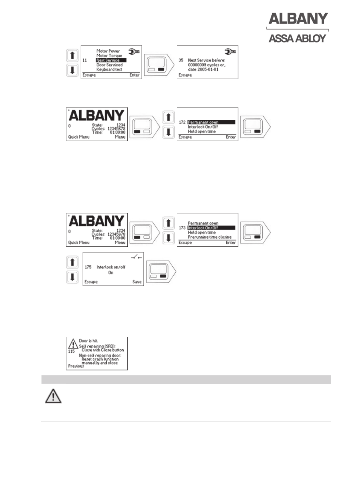
The date when the next service is due can be called up on the display.
Page 43
6410R0046_UM_Setup-Operation_MCC_EN11.docx 2012-07-16 43
5.10 Permanent opening of the door [1]
Permanent opening can be activated as following.
Permanent opening can be deactivated again by following the same sequence.
5.11 Deactivation of Interlock function [1]
Doors that are interlocked with one or more other doors have the option of
deactivating the interlock function. This could be necessary if maintenance work is
being carried out on one of the doors or the door shall be used as a single noninterlocked door, for example in summer.
The interlock function can be reactivated by following the same sequence.
5.12 Crash-system
In order to minimise the damage of the door in case of impacts doors can be
equipped with a crash-system. If there has been an impact to the door and the crash
sensor has been activated the door is stopped immediately. The following error
message appears.
WARNING
Risk of personal injury and material damage
Damaged parts of the door can endanger people or cause associated
consequential damages.
Ö After any impact the door should be checked thoroughly for possible damage.
Page 44
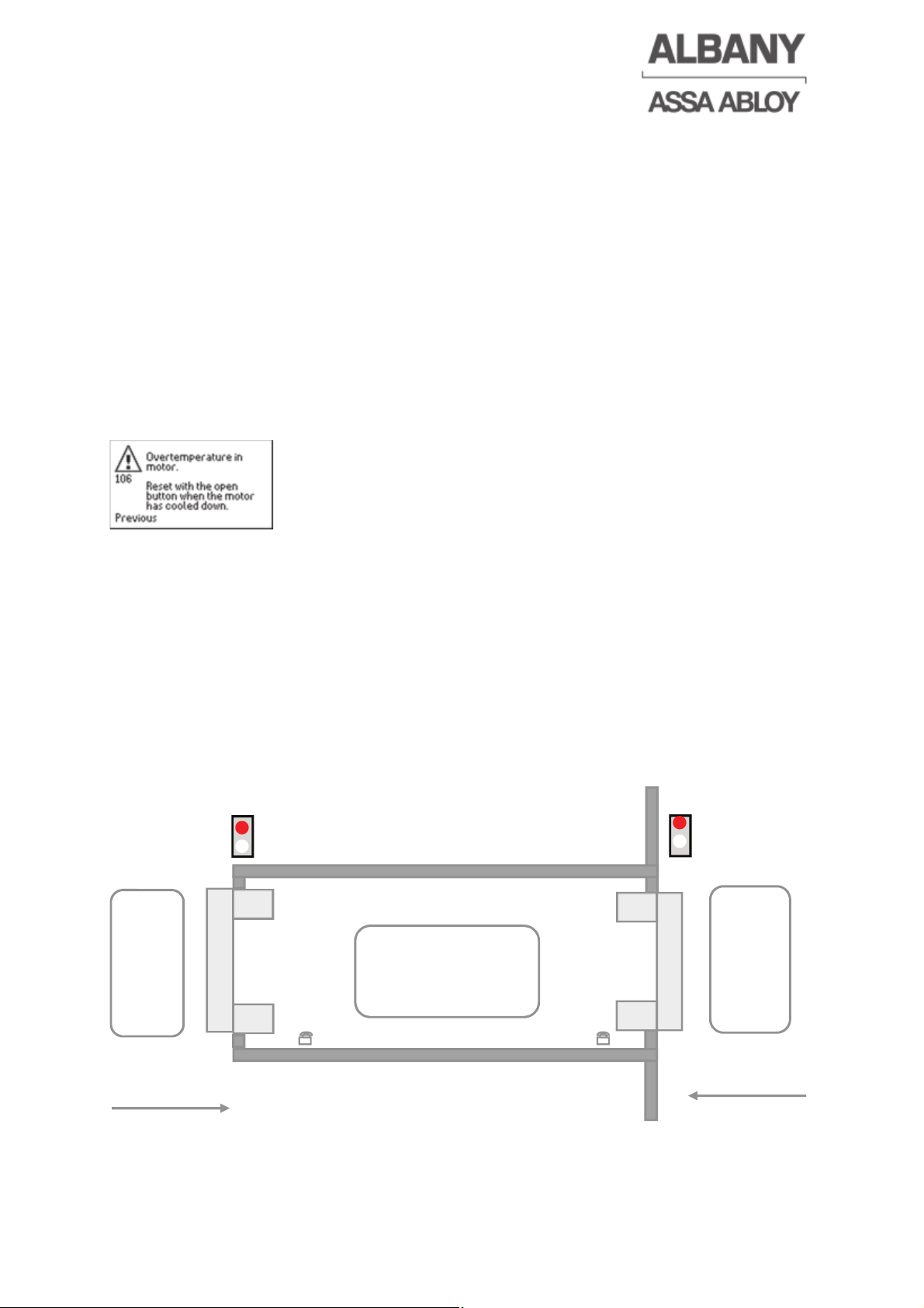
6410R0046_UM_Setup-Operation_MCC_EN11.docx 2012-07-16 44
5.12.1 Auto-repair crash system:
The door must be closed completely in hold to run mode. To do this the close button
on the keypad must be pressed until the breakaway mechanism is snapped-in in
place again and the door stops autonomous in the lower end position. Another
“Open” impulse will then make the door ready to use again.
5.12.2 Manually repairable crash system:
The breakaway mechanism has to be snapped-in in the side frame manually. After
this the door must be moved to the lower end position to quit the error, and it is then
ready for use again.
5.13 Thermal switch
To protect the drive motor three thermal switches are fitted in its windings. If the
switches trip the motor has become too hot and the drive is switched off immediately.
The following message will then appear:
Once the motor has cooled down the error can be acknowledged by pressing the
“Open” button. The door and the control system should then be checked for possible
mechanical or electrical faults. The control system should not be switched back on
until the motor has cooled down.
5.14 Airlock function [1]
An Airlock consists always of a door A and door B and is controlled automatically by
the airlock sequence. Each door has a separate control system. An airlock is used,
e.g. to prevent draughts in external doors.
5.14.1 Airlock sequence [1]
Front A
S1A
Do
or A
Do
or B
S1B
TL1A
TL1B
S2
M1B
M1A
FCA
FCA
FCB
FCB
Front B
Rear
A
Rear B
Direction A
Direction B
Page 45
# Description
S1A Actuator for Door A
S1B Actuator for Door B
S2 Middle actuator in the airlock
FCA Door line photocell Door A
FCB Door line photocell Door B
M1A Actuator for exiting the airlock Door A
M1B Actuator for exiting the airlock Door B
TL1A Traffic light for Door A
TL1B Traffic light for Door B
5.14.2 Airlock passage from A to B with middle actuator
The airlock sequence can only be started if both doors are closed and the actuators
are not activated. If the doors are equipped with traffic lights, both traffic lights must
be red or off (depending on the parameter setting).
As soon as a vehicle activates actuator S1A, which is programmed with the function
“Open with automatic closing after time (front)“, Door A opens. After the door has
been opened the airlock can be driven into. The door closes automatically after
driving into the airlock and after the close after passage time has expired or after the
hold open time, if the airlock has not been driven into.
Door B automatically opens if Door A is closed and middle actuator S2 of the airlock
has been actuated. The middle actuator pulse is saved with the airlock function. This
means that door B opens, even if the middle actuator is no longer activated, before
Door A is closed. The airlock can now be exited through Door B which automatically
closes after the hold open time or the close after passage time (depending on the
actuator). If another vehicle drives through Door B into the airlock before Door B is
closed, the airlock can be driven through in the other direction (but middle actuator
(S2) must be activated once). Direction detection in the airlock and therefore the door
initiated by the activation of the middle actuator is controlled by the door line
photocell. If the door line photocell is actuated and then the middle actuator is
activated, the direction is detected.
5.14.3 Airlock passage from A to B without middle actuator
The airlock sequence can only be started if both doors are closed and the actuators
are not activated. If the doors are equipped with traffic lights, both traffic lights must
be red or off (depending on the parameter setting).
If a vehicle activates actuator S1A, which is programmed with the function “Open with
automatic closing after time (front)“, Door A opens. After the door has been opened
the airlock can be driven into. The door closes automatically after driving into the
airlock and after the close after passage time has expired or after the hold open time,
if the airlock has not been driven into.
Door B opens automatically if Door A is closed, regardless of whether the airlock has
been entered or not. The airlock can now be exited through Door B which
automatically closes after the hold open time or the close after passage time
(depending on the actuator). If another enters the airlock through Door B before Door
B has started to close, direction detection is not set and Door A does not open.
Direction detection in the airlock is activated by the actuator which opened the closed
door or opens it while it is closing. Here it is possible that somebody enters the
6410R0046_UM_Setup-Operation_MCC_EN11.docx 2012-07-16 45
Page 46

airlock and the 2nd door does not open automatically. Therefore, in this airlock
option, a manual actuator for exiting the airlock should be provided at each door
within the airlock (M1A and M1B).
5.14.4 Long vehicle function at doors with middle actuator
This function is required if the vehicle to pass through the airlock is longer than the
distance between the two airlock doors.
The first door opens and the long vehicle can drive into the airlock. If the door line
photocell of the opened door and the middle actuator (S2) are simultaneously
activated, the second door opens automatically and the airlock can be completely
driven through. The first door closes after the close after passage time and the
second door after the hold open or close after passage time (depending on the
actuator). This function is also possible from the opposite side.
5.14.5 Manual long vehicle function
There is a possibility to have a separate long vehicle function, like a push button or
pull rope, connected to door A , independent of a middle actuator is used or not. See
Programming the inputs (chapter 4.14).
This long vehicle function is independent of the middle actuator and opens both
doors without delay.
5.14.6 Permanent opening function
In several cases, e.g. during hot weather, it can be advantageous to use Door A only
or Door B only. In this case the other door (here Door A) is set to permanent opening
using the permanent opening function at the display (chapter 5.10) or, if installed,
using the external permanent opening switch.
The opening pulse from the middle actuator (S2) then serves as a normal opening
pulse for the door without permanent opening (Door B). The external actuator (here
S1B) opens the door accordingly from the other side. The external actuator (here
S1A) which is connected directly to Door A operated in permanent opening, does not
have any function. In airlocks without middle actuator the external actuators (S1A or
S1B) acts as opening pulse for the door without permanent opening.
5.14.7 Direction detecting red traffic light on the outside of the airlock door
The red traffic lights are connected depending on the function “Traffic light red 24 V
DC front” (24 V DC traffic light) or “Traffic light (red/green) front” (traffic light via relay
contacts). The traffic lights via relay contacts require an additional MCC output to
switch off the traffic light if the door is closed.
Traffic light function settings: “Off if door is closed” or “Permanently on”
6410R0046_UM_Setup-Operation_MCC_EN11.docx 2012-07-16 46
Page 47
6410R0046_UM_Setup-Operation_MCC_EN11.docx 2012-07-16 47
Airlock function from A to B:
Position of Door A Traffic light
function of Door A
Position of Door B Traffic light
function of Door B
Door A closed
Red => Off/On (*1)
Green => Off
Door B closed
Red => Off/On (*1)
Green => Off
Door A when
opening
Red => On
Green => Off
Door B closed
Red => On
Green =>Off
Door A open
Red => Off
Green => On
Door B closed
Red => On
Green => Off
Door A when
closing
Red => On
Green => Off
Door B closed
Red => On
Green => Off
Door A closed
Red => On
Green =>Off
Door B when
opening
Red =>On
Green =>Off
Door A closed
Red =>On
Green =>Off
Door B open
Red =>On
Green =>Off
Door A closed
Red =>On
Green =>Off
Door B when
closing
Red =>On
Green =>Off
Door A closed
Red=>Off/On (*1)
Green =>Off
Door B closed
Red=>Off/On (*1)
Green =>Off
(*1) => Depending on the setting selected for the traffic light.
5.14.8 Actuators and time setting
The minimum close after passage time, which is possible for a airlock door, depends
on whether actuators S1A and S1B are detecting direction or not. Direction detecting
actuators are, e.g. radar detectors and loops detectors. Non-direction detecting
actuators are, e.g. infrared motion detectors and photocells.
After the airlock has been passed through (from A to B), actuator S1B sends a
renewed opening pulse to door B if the close after passage time is set shorter than
the time required to leave the actuator sensing range of S1B. This opening pulse
starts the close after passage and hold open time again and in airlocks without
middle actuator, Door A opens again after Door B is closed, if direction detection has
been set with the opening pulse. Direction detecting actuators should be used to
prevent this. Alternatively, the close after passage time can be set for so long that the
object has the possibility of leaving actuator sensing range before the close after
passage time has expired.
Due to saving of the middle actuator pulse even, e.g. a simple photocell can be used
as the middle actuator. Direction detection is then set by the door line photocell as
the middle actuator is not activated simultaneously.
Page 48
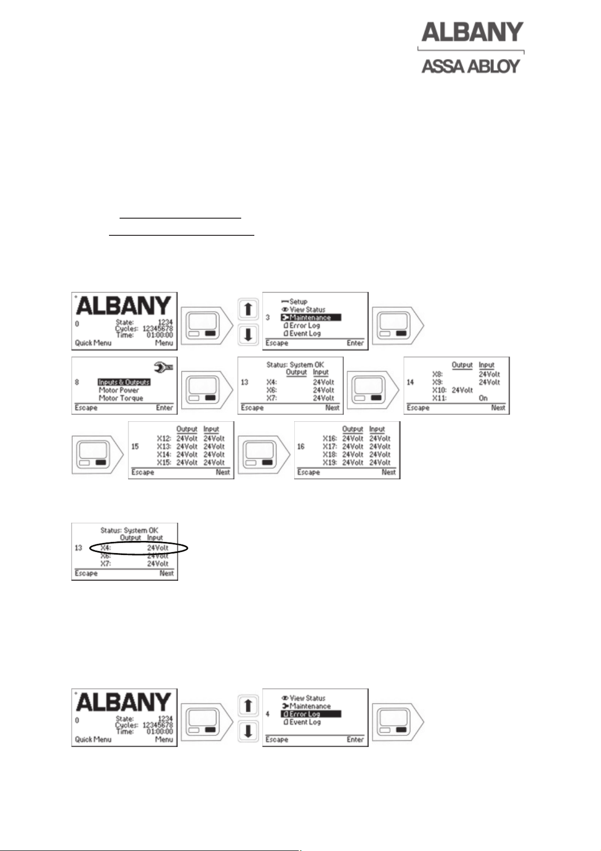
6 Fault correction
Contact the supplier or manufacturer for fault correction and repairs.
ALBANY Door Systems, Service Department
Am Mondschein 25
59557 Lippstadt, Germany
Tel.: +49 (0)2941 766 0
Fax: +49 (0)2941 766 294
Internet:
www.albanydoors.com
Email: [email protected]
6.1 Checking the inputs and outputs
On these display screens it is easy to see what voltage is present at each input and
output.
Example: In the electrical drawing the thermal switch is connected to X4. The
following view appears on the display:
In this case the system status is OK, there is 24V at the input of the control system
and the thermal contact appears to be in order.
6.2 Error log readout
Information and error messages are recorded in the error log of the control system
with the date and time.
The error log of the MCC can be read-out as follows:
6410R0046_UM_Setup-Operation_MCC_EN11.docx 2012-07-16 48
Page 49
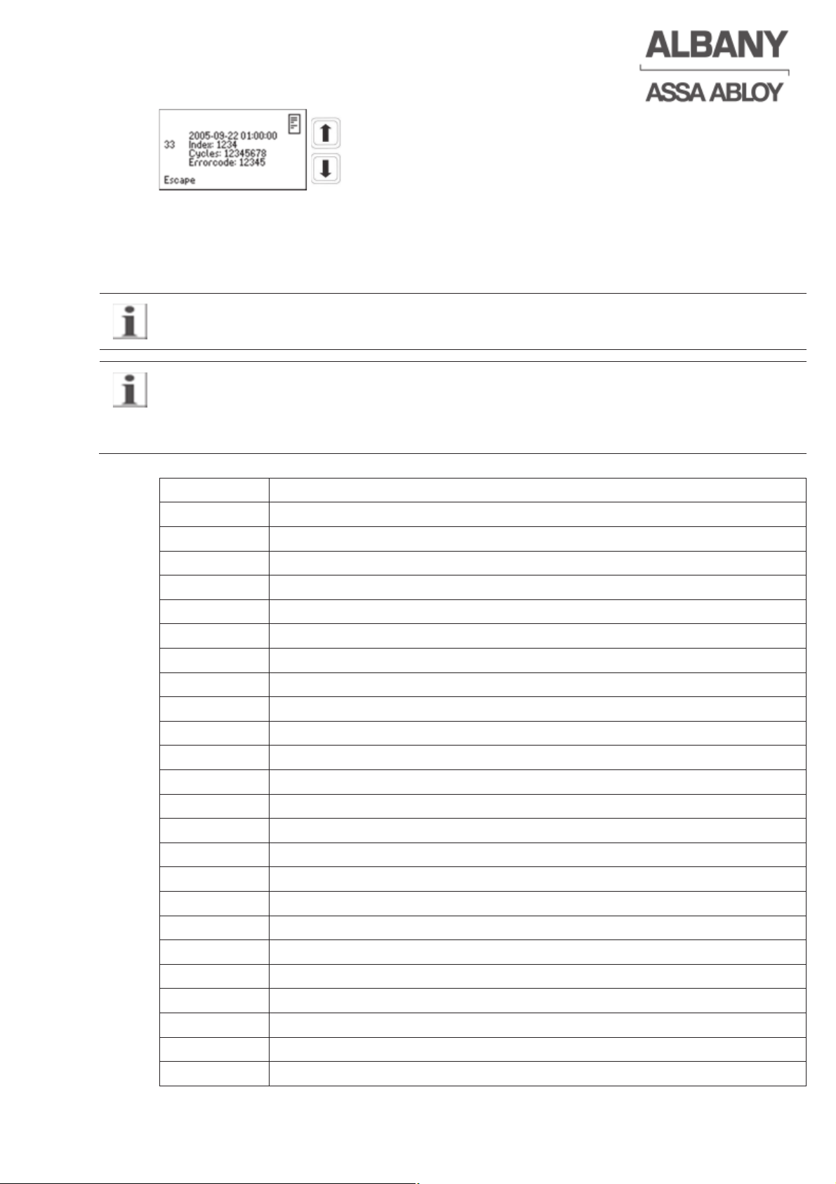
Every individual display view shows the date and time at which the error occurred, as
well as the index, cycle status and the error code. The index is a running counter,
which increases by one with each new error. The last occurred error is shown first.
The two arrow keys on the keypad can be used to scroll through all error messages.
Whenever the main switch is switched off a low voltage warning will be recorded in the
error log!
The error log is divided into 2 arrays.
0 – 500 array of information (e.g. configuration changed)
500 - … error messages (e.g. emergency manual handle actuated)
Error code Description of error
0 Text entry
1 Error log erased
2 System start
3 Programming PC connected
4 Programming PC disconnected
5 Setup of end positions started
10 Invalid data in the EEprom
16 Door run 1 cycle (not activated)
17 Door run 10 cycles (not activated)
18 Door run 100 cycles (not activated)
19 Door run 1000 cycles (factory setting)
20 Reference limit switch position tolerance >10 impulses
21 Reference limit switch position tolerance >20 impulses
22 Reference limit switch position tolerance >50 impulses
23 Reference limit switch position tolerance >100 impulses
24 Reference limit switch position tolerance >150 impulses
30 IGBT temperature > 60°C (140°F)
31 IGBT temperature > 70°C (158°F)
32 IGBT temperature > 80°C (176°F)
33 IGBT temperature > 90°C (194°F)
34 IGBT temperature > 100°C (212°F)
41 Endurance test started
42 Endurance test stopped
43 State changed externally
6410R0046_UM_Setup-Operation_MCC_EN11.docx 2012-07-16 49
Page 50
6410R0046_UM_Setup-Operation_MCC_EN11.docx 2012-07-16 50
44 Invalid positions
100 DSP, electrical safety edge activation
101 DSP, 18 V absent
103 DSP overvoltage warning
104 Overvoltage at DSP
105 DSP over temperature warning IGBT
106 Normal function (no reference search necessary)
107 Reference search after switch-on
108 Set up end positions
109 Overload warning
110 Safety function activated for closing impulse
111 DSP error
112 Valid door position saved
500 Invalid config file
503 Software logic error
504 DSP communication error
505 Software routines disturbed
506 Date or time out of valid range
507 Date/time out of valid range revised
508 Door moved from closed position without motor power
509 RAM test error
510 ROM test error
511 Closing speed higher than allowed
520-526 Communication error DSP – M16
1004
Electrical safety edge / pre-running photocell circuit interrupted during
opening
1005 Electrical safety edge or the pre-running photocell activated
1006 Thermal contact tripped
1009 Movement of the door was not recognized
1010 Encoder registers unauthorised movement
1011 Emergency manual lever operated
1013 Reference limit switch activated out of valid range
1014 Door locked by other door (airlock)
1015 Crash sensor has tripped
1016 Pass door open
1018 Safety 1 defect
1019 Door line photocell defect
1022 Safety 2 defect
1023 Internal frequency converter error
1024
Electrical safety edge / pre-running photocell interrupted in door open
position
Page 51
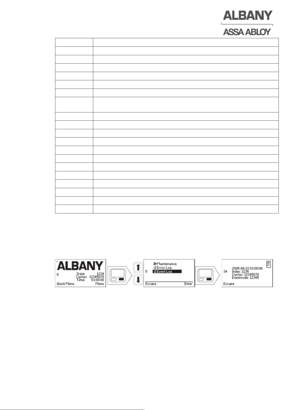
1025 Internal error
1026 Reference limit switch not activated with opened door
1027 Error in safety edge input
1028 Error in emergency stop input
1029 Input voltage at emergency stop input too high
1030 Earth fault in the 24 V circuit (low voltage)
1031 Earth fault in the 24 V circuit (high voltage)
1032
Opening height not reached during cyclical self-test (only for RR 300
Plus F+R)
1033 Breakaway function activated (only for US doors)
1100 Undervoltage – only in UPS mode activated
1101 Phase error
1102 Overvoltage
1104 Incorrect main voltage
1105 Overcurrent >25A
1106 Motor blocked or encoder without signal
1108 Over temperature
1110 Wrong hardware
1112 Brake circuit overcurrent
1115 3 Phase error
1200 Electrical safety edge or pre-running photocell activated
6.3 Event log readout
Important service messages and carried out service works are recorded in the control
system’s event log.
The event log of the MCC can be read-out as follows:
Every individual display view shows the date and time at which the event occurred,
as well as the index, cycle status and the event code. The index is a running counter,
which increases by one with each new event. The last occurred event is shown first.
The two arrow keys on the keypad can be used to scroll through all event messages.
6410R0046_UM_Setup-Operation_MCC_EN11.docx 2012-07-16 51
Page 52
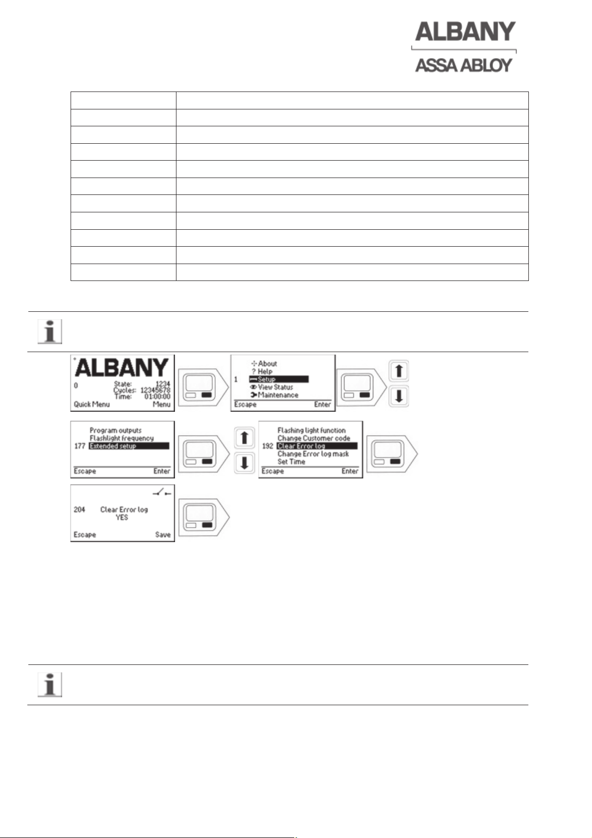
6410R0046_UM_Setup-Operation_MCC_EN11.docx 2012-07-16 52
The following actions are recorded in the control system’s event log:
Event code Event
1 Event log cleared
2 Config file changed
3 Application software changed
5 Information note in event log added or changed
10 Door service required
11 Door serviced
20 Control system cycle counter changed
21 Door cycle counter changed
22 Function of inputs/outputs changed
23 Time changed
6.4 Clear error log [3]
The error log should only be cleared by Albany Door Systems Service as all existing
error messages are permanently erased.
6.5 Altering the error mask [3]
Only for Albany Door Systems Service Team.
6.6 Error messages / error codes (only for doors without display)
For doors without a display the most important error messages are shown by the
flashing status light:
e.g. 3 flashes correspond to the error code position error.
For purposes of clarity only the most important errors are signalized by codes of
flashes by the status light (option).
Page 53
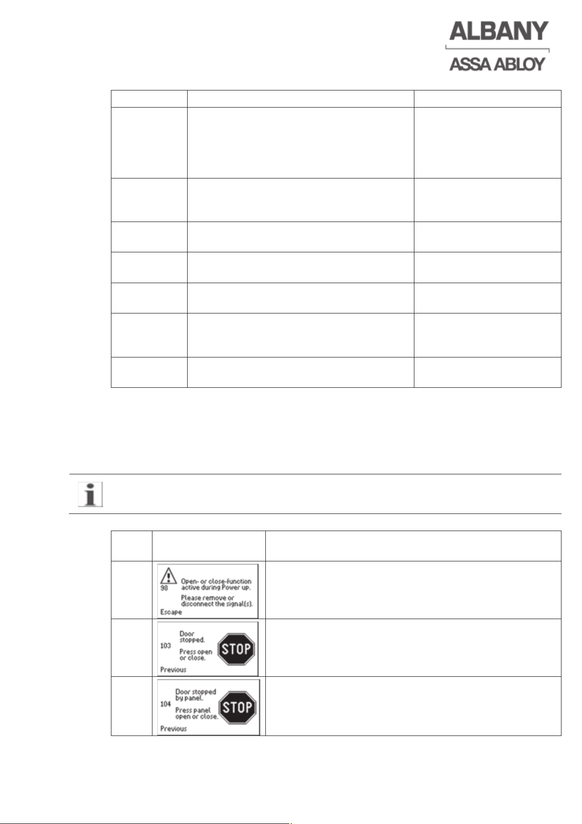
6410R0046_UM_Setup-Operation_MCC_EN11.docx 2012-07-16 53
Error code Error Corrective action
1 flash
(slow)
Stop button or emergency stop pressed,
electrical safety edge activated according
to the max consecutive activations setting
in a row, interlock device activated, hold
brake released
Press reset
2 flashes
(slow)
Crash activated For auto-repairing doors
close the door, otherwise
perform manual repairs
3 flashes
(slow)
Position of door incorrect, lost positions
after start-up
Perform reference search
4 flashes
(slow)
Excess temperature of control system or
motor, overload
Cool motor or control
system
5 flashes
(slow)
Sensor error
6 flashes
(slow)
The main voltage is set incorrectly. Correct the main voltage
setting in the installation
menu
7 flashes
(slow)
Internal error Call the Albany Door
Systems Service Team
6.7 Error messages (only for doors with displays)
The following error messages are listed in ascending numerical order according to
the display screen number. This number can be taken from the left-hand side of the
display for every display message, regardless of the language. For example, 103 for
“Door stopped“.
If no corrective action is specified, the error cannot be repaired or the error message
appears again, please contact Albany Door System Service.
View-
No
Display view Corrective action
98
Check impulse actuator.
103
Release stop button if necessary. Acknowledge by
actuating open or close command.
104
Acknowledge by actuating open or close button on the
display.
Page 54
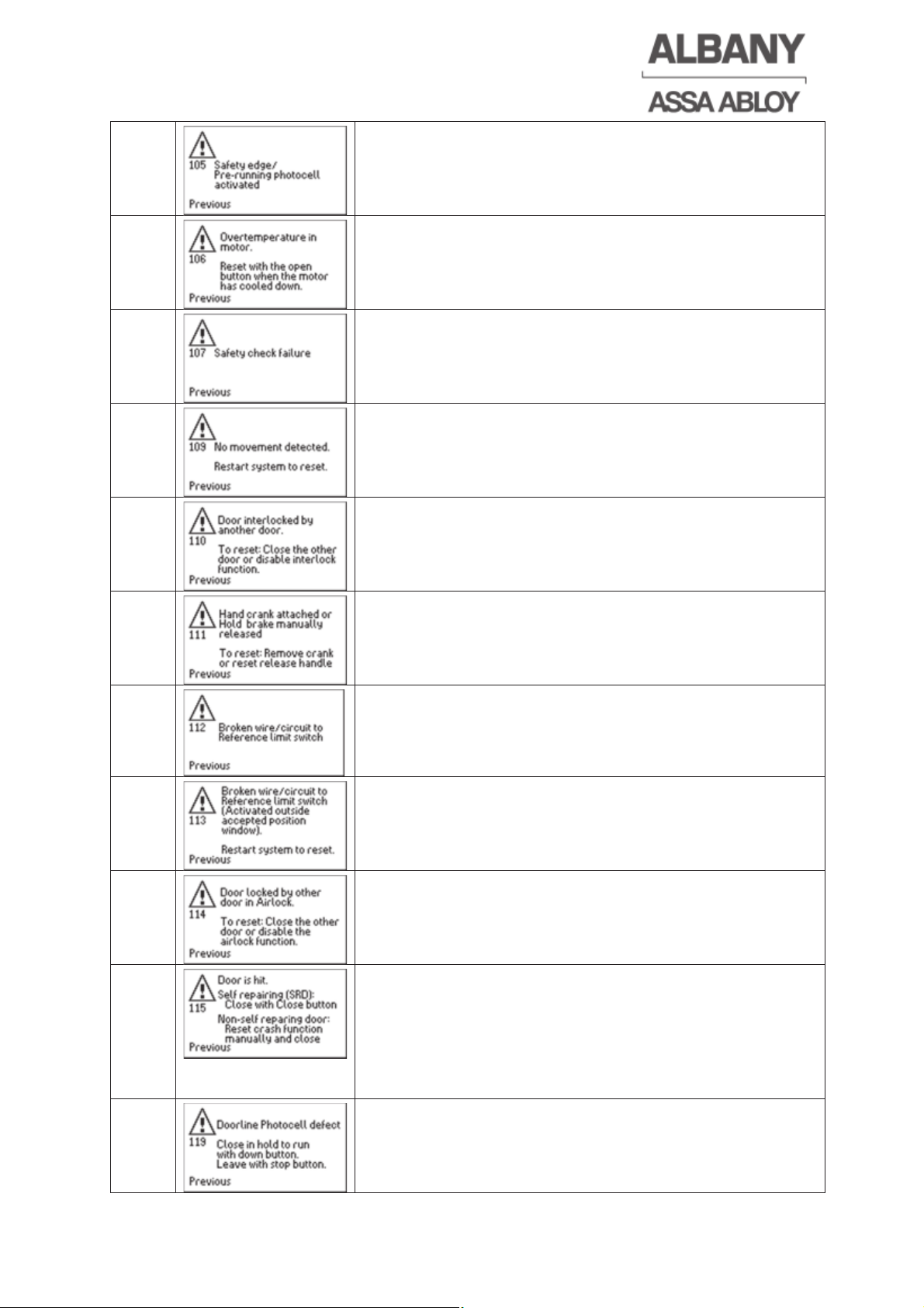
6410R0046_UM_Setup-Operation_MCC_EN11.docx 2012-07-16 54
105
Check pre-running photocell or electrical safety edge.
Clean pre-running photocell. Acknowledge by
actuating close button on the display.
106
Switch off the control system, allow the motor to cool
and, if necessary, clean the motor’s ventilation slots.
107
Internal safety test faulty.
RAM/ROM tests, speed monitoring or other internal
safety tests faulty.
109
Encoder gives incorrect signals. The motor or the top
roll is blocked.
110
The door is locked by another door. Close the other
door to reset this.
111
Return the emergency manual lever to its original
position or remove the emergency hand crank.
112
Check wiring reference limit switch.
113
The reference limit switch was activated outside
accepted door position window which is given by the
encoder or the reference limit switch circuit is broken.
114
The door has been locked in place by the other airlock door. To reset, close the other door completely or
deactivate the air-lock function.
115
For doors without an auto-repair crash system close
the door completely after repairs to acknowledge the
error message. For doors with an auto-repair crash
system close the door until the bottom profile engages
automatically again and the lower end position is
reached.
119
Exclude influence from other infrared (IR) sensors and
check alignment of the door line photocell.
Page 55
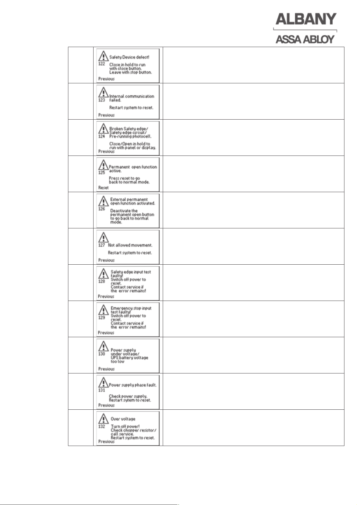
6410R0046_UM_Setup-Operation_MCC_EN11.docx 2012-07-16 55
122
Check function and wiring of additional safety devices.
123
Please call the Albany Door Systems Service Team.
124
Check function and wiring of electrical safety edge /
the pre-running photocell.
125
Permanent opening has been activated. Press left
function key for reset.
126
External permanent opening has been activated. To
deactivate this, remove the permanent opening signal.
127
The encoder detects an unauthorized movement of the
door.
128
Please call the Albany Door Systems Service Team.
129
Please call the Albany Door Systems Service Team.
130
Undervoltage detected in the main voltage supply.
Check the main voltage. Verify that the original config
settings for the door are correct. Recharge the
batteries in case of doors with UPS.
131
Check main voltage and supply stability. To reset
switch the main switch off and back on again.
132
Overvoltage in the control system. Turn off the main
switch and check the brake resistor, the main voltage
and control settings of main voltage.
Page 56
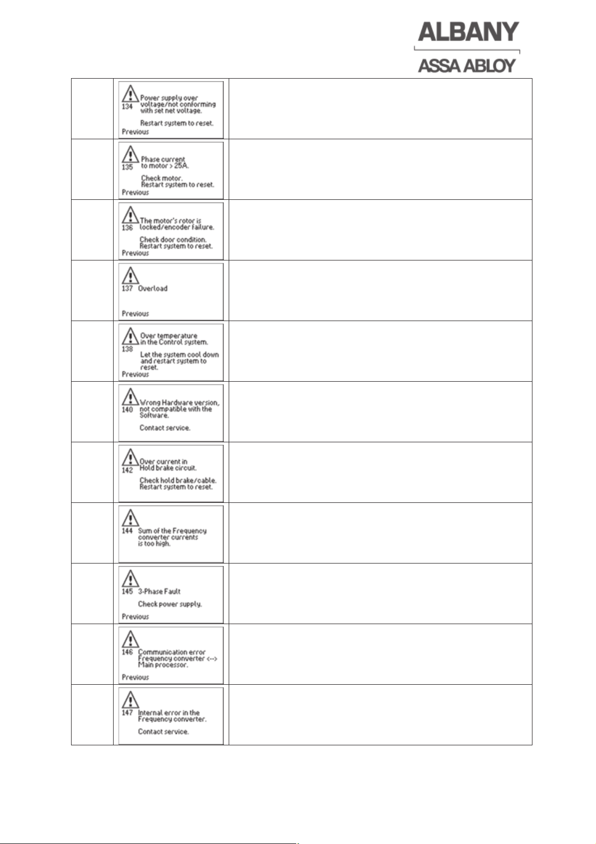
6410R0046_UM_Setup-Operation_MCC_EN11.docx 2012-07-16 56
134
Check the supply voltage and the parameter for the
main voltage.
135
The motor current is too high. Check that the door
mechanism is running smoothly.
136
Check that the motor and the door mechanism is
running smoothly. Check alignment and function of the
encoder.
137
The control system is overloaded. Check that the door
mechanism is running smoothly.
138
Overheating of the control system. Switch off the main
switch and allow the control system to cool.
140
Please call the Albany Door Systems Service Team.
142
Check the brake and the brake cable.
144
Check that the door mechanism is running smoothly.
145
3-phase voltage failure or break-down of the supply
voltage occurred. Check the supply voltage and the
fuses.
146
Please call the Albany Door Systems Service Team.
147
Please call the Albany Door Systems Service Team.
Page 57
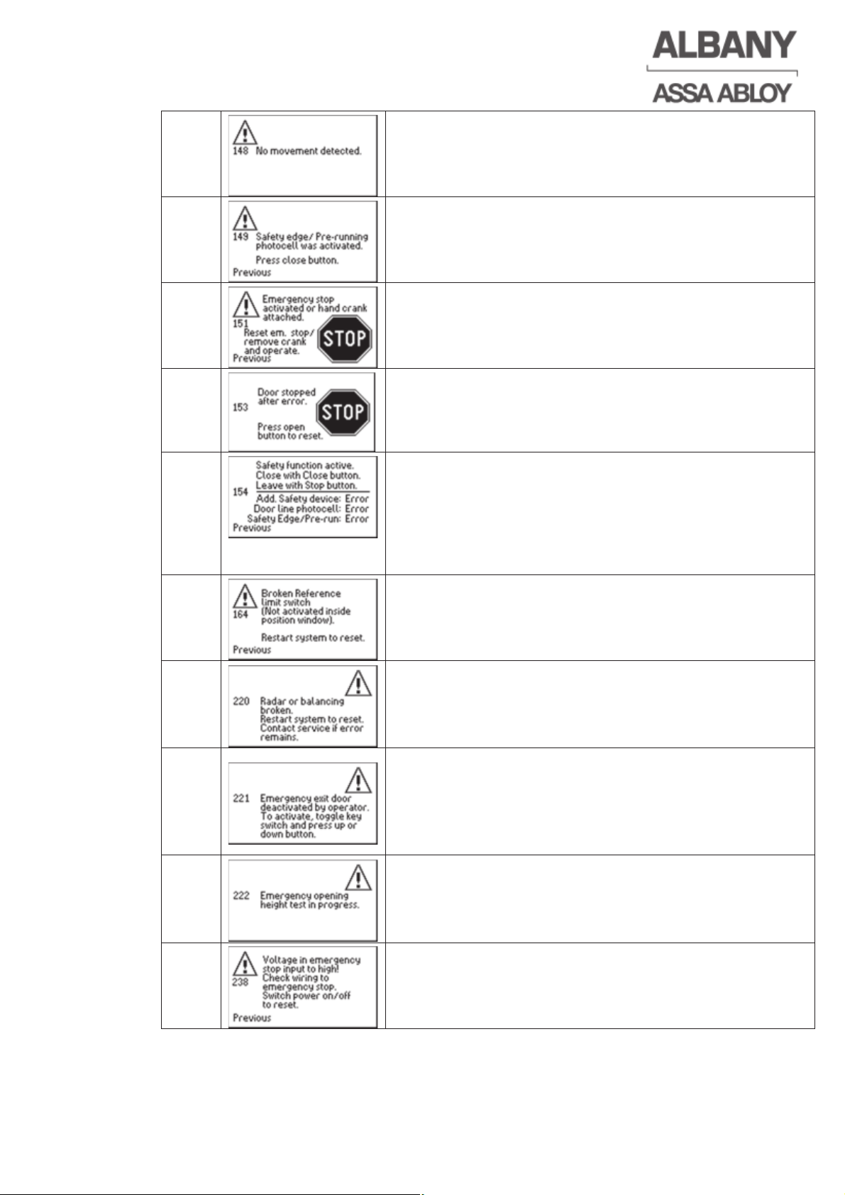
6410R0046_UM_Setup-Operation_MCC_EN11.docx 2012-07-16 57
148
The door is blocked or the position encoder is sending
incorrect signals. Check that the door mechanism is
running smoothly. Check the function of the encoder.
149
Check electrical safety edge / the pre-running
photocell. Clean pre-running photocell. Press the
“Open” or “Close” buttons to reset.
151
Release the emergency stop or remove emergency
hand crank and start the door using the “Open” or
“Close” command.
153
Acknowledge by actuating open command.
154
The door’s safety function is active. This means that
there is something wrong with one or more of the
door’s safety devices. The current status of the safety
devices connected can be seen on the display. Once
all safety devices are functioning correctly again you
can exit or leave the mode by pressing the stop button.
164
Check reference limit switch and adjust if necessary.
220
Only for emergency exit door RapidRoll 300 plus F+R
Check springs, belts and spring/belt break switches.
Check wiring of the radar and spring/belt break
switches.
221
Only for emergency exit door RapidRoll 300 plus F+R
Toggle deactivation key-switch to switch-on
emergency exit function. If message continues to be
displayed, check the switch and wiring and replace if
necessary.
222
Only for emergency exit door RapidRoll 300 plus F+R
No measures are necessary after successful
completion. If performance of the self-opening-test is
faulty, consider other fault messages.
238
The voltage at the emergency stop input is too high.
Check wiring of emergency stop circuit.
Page 58
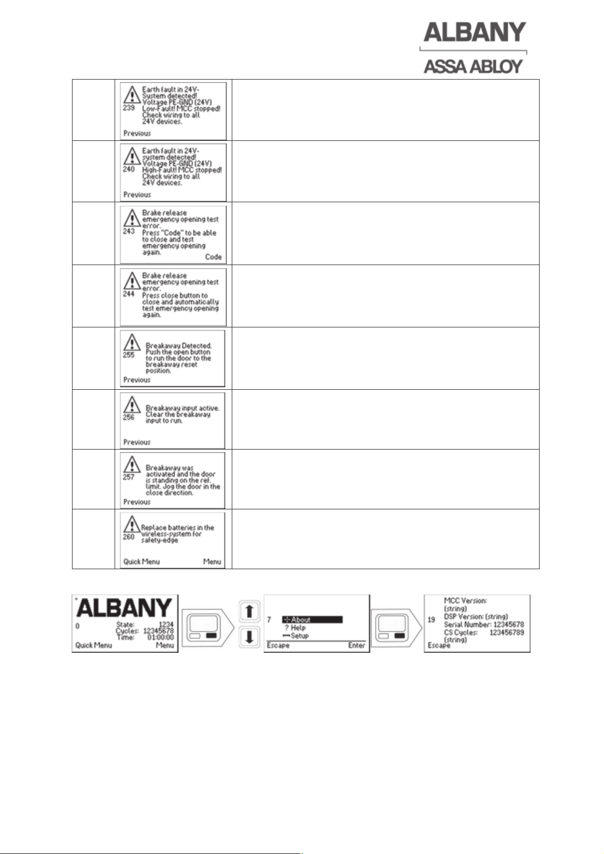
6410R0046_UM_Setup-Operation_MCC_EN11.docx 2012-07-16 58
239
An earth fault has been detected in the 24 V circuit.
Check the wiring of all 24 V loads.
240
An earth fault has been detected in the 24 V circuit.
Check the wiring of all 24 V loads.
243
Only for emergency exit door RapidRoll 300 plus F+R
Door can be released with right function key “Code”
and input of the customer code. The self-tests are then
repeated. The message 222 is indicated afterwards.
244
Only for emergency exit door RapidRoll 300 plus F+R
Press Close button for renewed checking of the self-
opening height. No measures are necessary after
successful completion.
255
Only for US doors:
There has been a door impact. Acknowledge by
moving door to upper end position of the door
(breakaway position).
256
Check breakaway-sensors.
257
Follow instructions in the display view. Check the
function and wiring of the reference limit switch.
260
Replace the batteries of the radio system only with
equivalent batteries. Operation of the door in hold to
run mode is possible.
6.8 Hardware and software version readout
The hardware and software versions used can now be taken from the display.
Page 59
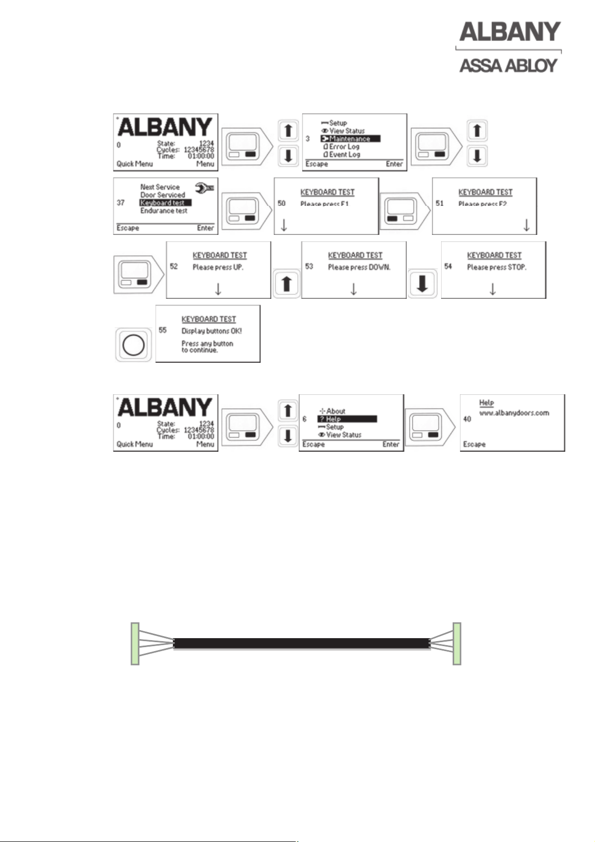
6410R0046_UM_Setup-Operation_MCC_EN11.docx 2012-07-16 59
6.9 Keypad test
This test is used to check whether the individual keys on the keypad are working.
6.10 Technical support
The display lists the contact information for technical support or the website on which
the latest contact information for local technical support can be retrieved.
6.11 Clone function when replacing the control system
The software can be copied from one control to the other with the clone function. To
clone a faulty MCC system the following components are needed:
• A new MCC control system with at least pre-installed boot software.
• The clone cable (therefore contact Albany Door Systems Service).
• An MCC display with cabling (if not already installed at the door)
X27
(MCC-1)
X27
(MCC-2)
Clonecable
Page 60
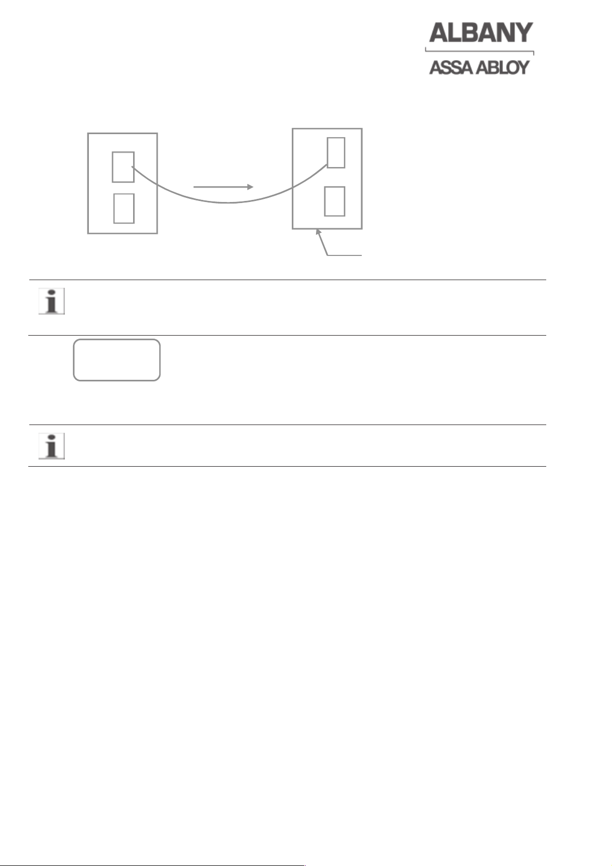
At older control systems without the “Ready for Cloning” label, the changed customer
settings in the display should be checked after each cloning procedure! These are,
e.g. function changes at the inputs and outputs, etc.
“Ready for cloning” label
Follow the step-by-step instruction to perform a complete cloning:
The only cable that shall be connected to the faulty MCC is the cloning cable.
1. Turn off all power.
2. Disconnect and remove the broken MCC from the door.
3. Install the new MCC including the compl. electrical-connections.
4. Connect the cloning cable to both, the new MCC and to the faulty MCC (plug
X27).
5. If no MCC display is normally connected to the door then temporary connect
an extra one to the new MCC.
6. Turn on the power.
7. Select “CLONE” on the display.
Wait until cloning is finished and OK is displayed. If the cloning has not been
performed successfully the procedure can be restarted from point 6 by cycling
the power.
8. Turn off the power.
9. Remove the faulty system, the cloning cable and eventually the extra MCC
display.
10. Turn on the power.
11. Test the door.
Defektive MCC New MCC
Main voltage
(only at new MCC)
No main voltage
X27
X27
Clone
c
able
X1
X1
Ready for
Cloning ¥
6410R0046_UM_Setup-Operation_MCC_EN11.docx 2012-07-16 60
Page 61
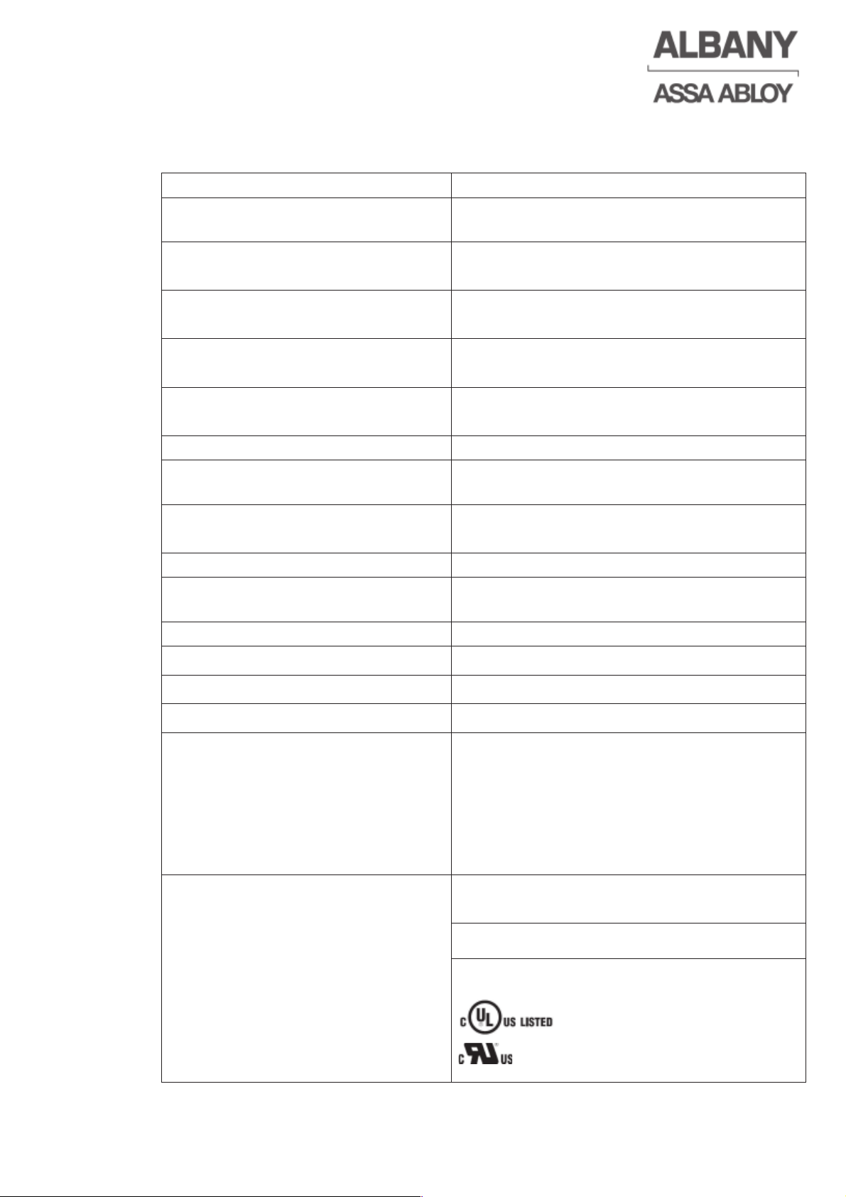
7 Technical data and control system label
7.1 General data
Housing material anodized aluminium
Dimensions of housing WxHxD,
without cable glands and end plates
220 x 380 x 100 mm (14,5" x 8,6" x 4")
Main voltage 3~ PE; 50-60 Hz
220-480 V -10%/+5%
Max. output power 5,5 kVA
2,3 kVA continuous average max. power
Max. output nominal current 8 A (FLA: Full Load Ampere)
12,7 A Boost for 0,5 sec.
Operating temperature range -20°C - +40°C
-20°C - +45°C RP-doors
Protection class IP 55
External fuse by customer 10 – 16 Ampere B or C characteristic or
comparable
Residual current protection (RCD`s)
(only if needed)
AC/DC sensitive short-time delayed type B
Observe the instructions in chapter 4.2.1!
Residual current caused by MCC 7mA according EN 60335-1
Control voltage / external supply 24 VDC / max. 500 mA
with display max. 450 mA
Brake voltage 96 – 196 VDC / max. 300 mA
Programmable inputs 8
Programmable outputs 8
Weight approx.. 5,2 kg
Conformity Europe
2006/42/EC, 2004/108/EC
2006/95/EC, EN13241-1: 2004
EN ISO 13849-1:2008
EN 12978:2009
EN 12453:2000
EN 60335-1:2002
TÜV Nord certification
Conformity USA and Canada
UL508C:2002
CSA22.2 No.247:1992
File-Nr.: E326871
Category:
NMMS, NMMS2
NMMS7, NMMS8
6410R0046_UM_Setup-Operation_MCC_EN11.docx 2012-07-16 61
Page 62
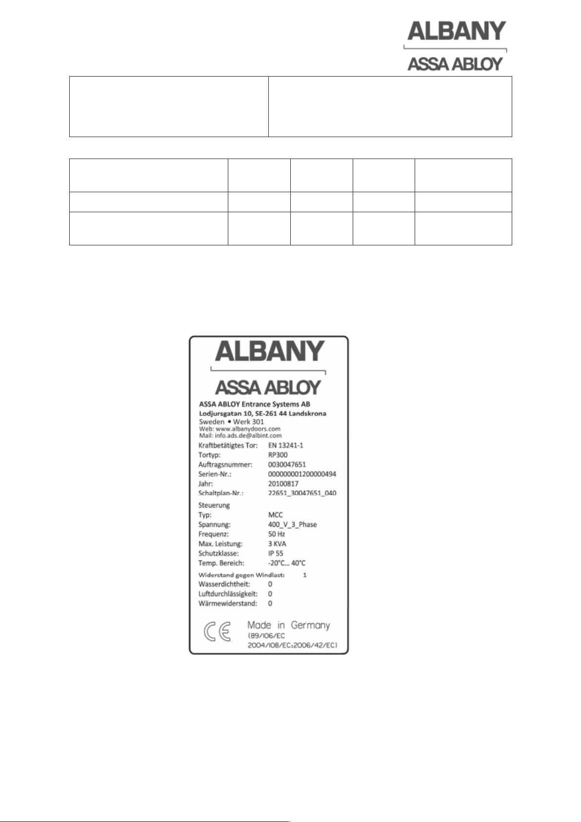
6410R0046_UM_Setup-Operation_MCC_EN11.docx 2012-07-16 62
Motor cable length
Without EMC filter: Max. 2m (industry and
residential / commercial environments)
With EMC filter: Max. 30m (industry and
residential / commercial environments)
7.2 Classifications of safety circuits to EN ISO 13849-1
Function Category MTTFD DCAVG
Performance
Level
Input emergency stop 3 4633 90 D
Input electrical safety edge
or the pre-running photocell
2 746 90 D
7.3 Labeling
Page 63
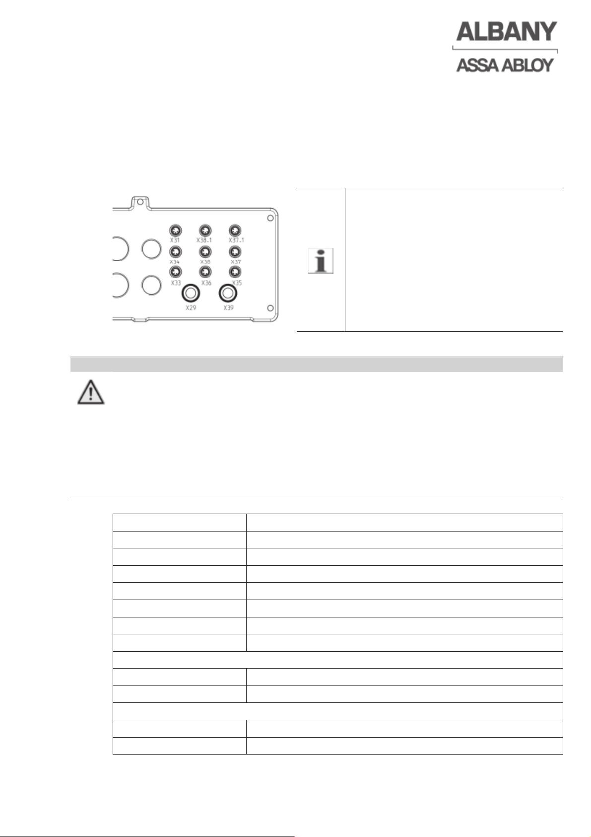
6410R0046_UM_Setup-Operation_MCC_EN11.docx 2012-07-16 63
8 Optional MCC – Units
8.1 Flange plate with integrated junction box
The flange plate with integrated junction box allows an easy and time-saving wiring of
the door sensors to the MCC .
8.1.1 Connector assignment junction box
If a safety edge is connected, it may be
necessary to use a cable adapter (see
electrical drawing)
DANGER
Serious injuries at the unsecured door. Loss of the CE conformity.
The inputs and outputs of the junction box and the MCC are interconnected
parallel. A simultaneous use can lead to a loss in safety and to unexpected
behaviour of the door.
Ö The corresponding in- and outputs of the junction box and the MCC should not
be wired/used parallel.
Ö Observe electrical drawing of the door.
Ö Simultaneous use according to order-related electrical drawing is allowed.
Terminal Description
X 29 Encoder
X 31 Thermal contact/hand lever
X 33 Reference limit switch
X 34 Reserve I/O 5
X 35 Receiver, door line photocell
X 36 Transmitter, door line photocell
X 39 Display
At doors without crash:
X 37 Receiver pre-running photocell or safety edge
X 38 Transmitter pre-running photocell
At doors with crash:
X 37.1 Crash and receiver pre-running photocell
X 38.1 Crash and transmitter pre-running photocell
Page 64
6410R0046_UM_Setup-Operation_MCC_EN11.docx 2012-07-16 64
8.2 Interface board
The MCC can be supplemented with a multifunctional interface board which
increases the scope of the control system. There are 3 dry relay changeover contacts
(8A, 250V~ / 10A, 240V-) on the interface board for controlling external components,
which are controlled directly through the MCC outputs. In addition, the board offers
the possibility to move 3 inputs from the MCC onto the interface board. This enables
add-ons, e.g. loop detector or radio receiver to be mounted on the top-hat rail and to
be directly wired with the inputs of the MCC. The terminal block X108 (terminal 1-14)
can be used e.g. as an interconnection terminal block.
8.2.1 Terminal assignment of the interface board
DANGER
Risk of electrical shock
Infringement of protection class
Ö If used, the protective earth terminal strip (earth) must be connected to the
existing protective earth connection.
Cross-section, spring-loaded terminals X100-X103, X108, protective earth
connection:
0.14-1.5 mm
2
without wire end sleeve,
0.14-1.5 mm
2
with wire end sleeve without plastic collar to DIN 46228-1
0.14-0.75 mm
2
with wire end sleeve with plastic collar to DIN 46228-4
Cross-section, spring-loaded terminals X104-107:
0.14-1.5 mm
2
without wire end sleeve,
0.14-1.0 mm
2
with wire end sleeve without/with plastic collar to DIN 46228-1/-4
Page 65
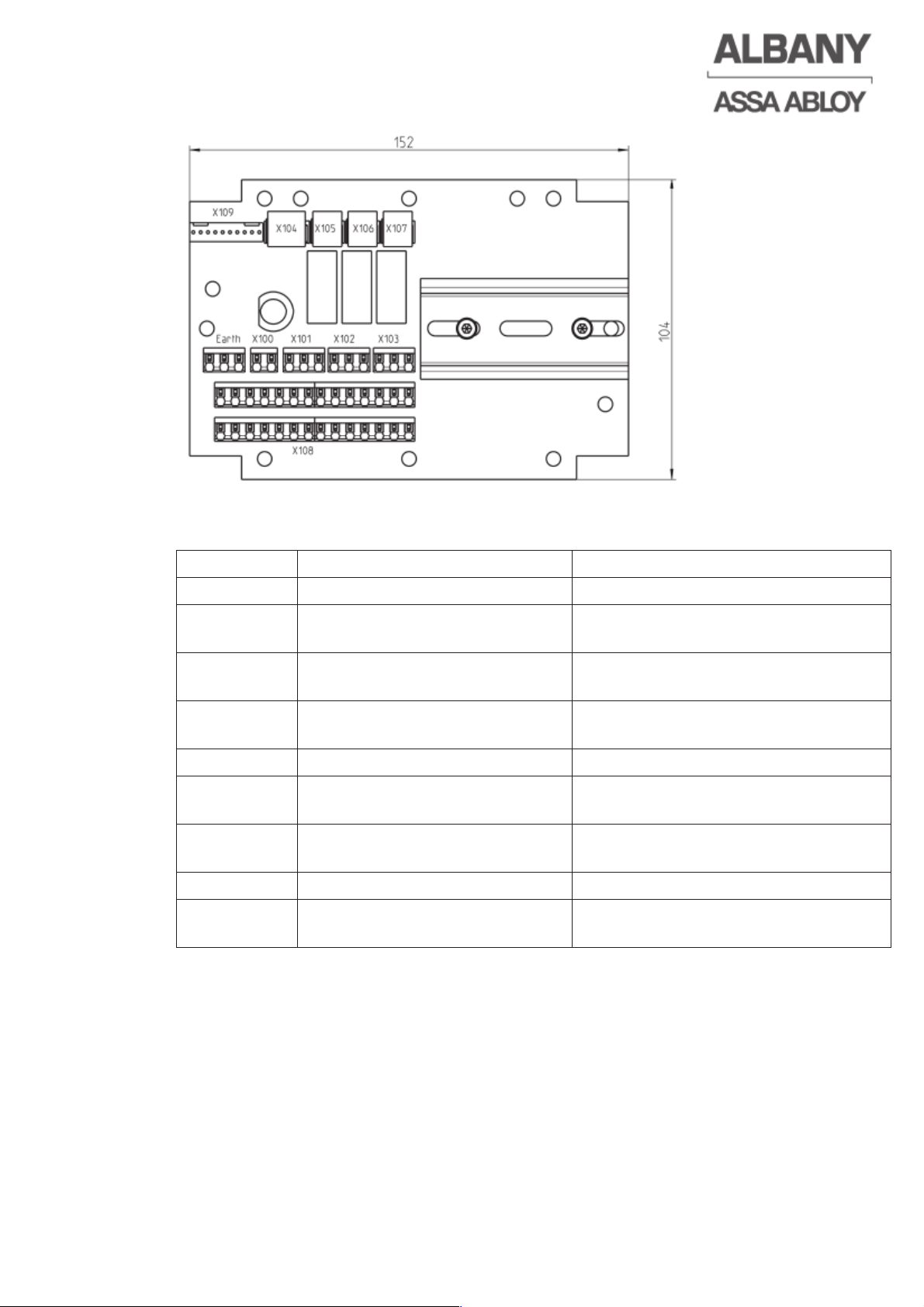
6410R0046_UM_Setup-Operation_MCC_EN11.docx 2012-07-16 65
Terminal Description Pin assignment
X 100 Connection of fuse F1 T2A => Terminal 1 and 2
X 101
Dry changeover contact of
relay KA1
1=COM, 2=NO, 3=NC
X 102
Dry changeover contact of
relay KA2
1=COM, 2=NO, 3=NC
X 103
Dry changeover contact of
relay KA3
1=COM, 2=NO, 3=NC
X 104 (not used)
X105-X107
Programmable inputs of the
MCC
1= 24V DC, 2=Input, 3= GND, see
order-related electrical drawing
X 108
interconnection terminal block
with 14 terminals
X 109 Connecting cable to the MCC
Earth
Terminal for protective earth
connection
Page 66
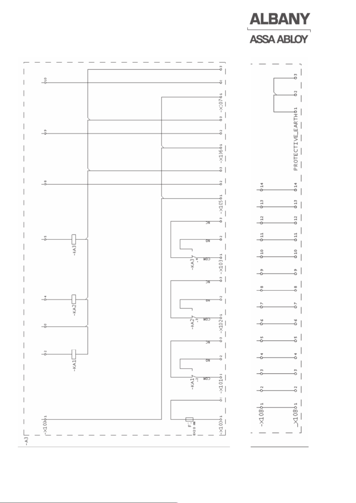
6410R0046_UM_Setup-Operation_MCC_EN11.docx 2012-07-16 66
8.2.2 Schematic electrical drawing of the interface board:
Page 67
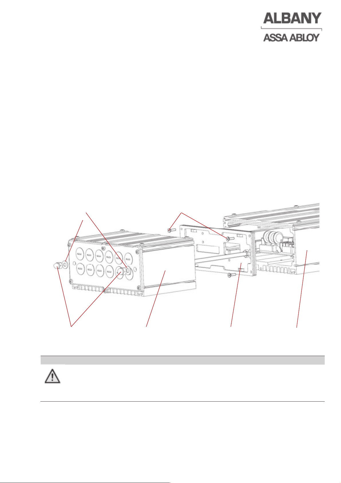
6410R0046_UM_Setup-Operation_MCC_EN11.docx 2012-07-16 67
8.3 MCC extension
The MCC can be supplemented with a multifunctional extension which increases the
scope of the control system and provides reserve space for additional components.
The MCC extension enables various plug-on boards for radio receivers and loop
detectors to be directly installed. The connection with the MCC is made using a 40pin ribbon cable and therefore reduces the wiring required for the installation. With
the MCC extension it is possible to connect the whole sensor/actuator wiring at the
door to the extension and, at the customer's request, to guide the inlets for this
through the extension housing.
There are 4 dry relay changeover contacts (6A, 250V~ / 3A, 30V-) on the extension
board for controlling external components and which are controlled directly through
the MCC outputs.
8.3.1 Mechanical installation of the MCC extension
As shown, the prepared connection plate must be screwed onto the MCC using the
four countersunk screws. The extension housing is then pushed onto the connection
plate and fixed using the two cap nuts.
CAUTION
Risk of material damage
Destruction of the MCC and the extension board by moisture.
Ö To seal the housing, ensure that the
two plastic plain washers are used under the
two cap nuts
Plastic plain washers
Countersunk screws
Cap nuts MCC-extension housing connection plate MCC
Page 68
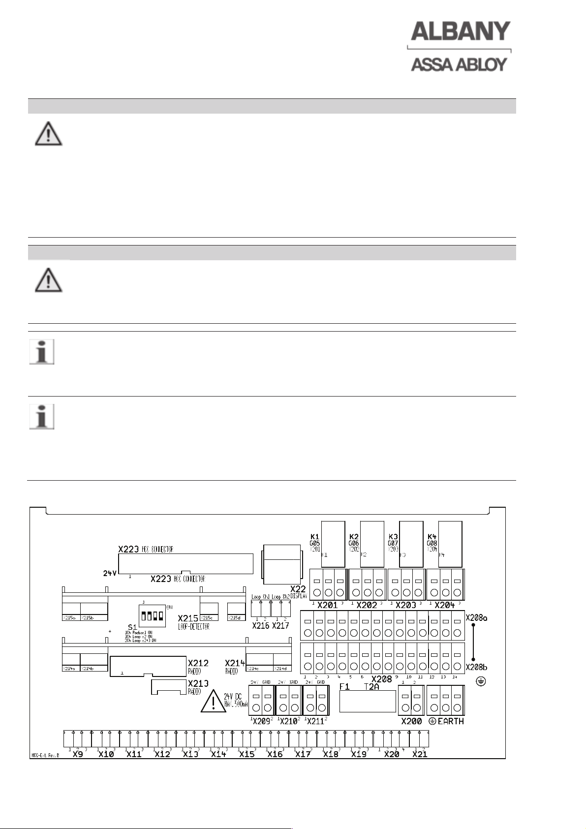
8.3.2 Terminal assignment of the MCC extension board
DANGER
Serious injuries at the unsecured door. Loss of the CE conformity.
The inputs and outputs the extension board and the MCC are interconnected
parallel. A simultaneous use can lead to a loss in safety and to unexpected
behaviour of the door.
Ö The corresponding in- and outputs of the extension board and the MCC should
not be wired/used parallel.
Ö Observe electrical drawing of the door.
Ö Simultaneous use according to order-related electrical drawing is allowed.
DANGER
Risk of electrical shock
Infringement of protection class
Ö If used, the protective earth terminal strip (earth) must be connected to the
existing protective earth connection.
Cross-section, spring-loaded terminals X9-21, X216-217:
0.14-1.5 mm
2
without wire end sleeve,
0.14-1.0 mm
2
with wire end sleeve without/with plastic collar to DIN 46228-1/-4
Cross-section, spring-loaded terminals X200-211, protective earth connection:
0.14-2.5 mm
2
without wire end sleeve,
0.14-2.5 mm
2
with wire end sleeve without plastic collar to DIN 46228-1
0.14-1.5 mm
2
with wire end sleeve with plastic collar to DIN 46228-4
6410R0046_UM_Setup-Operation_MCC_EN11.docx 2012-07-16 68
Page 69
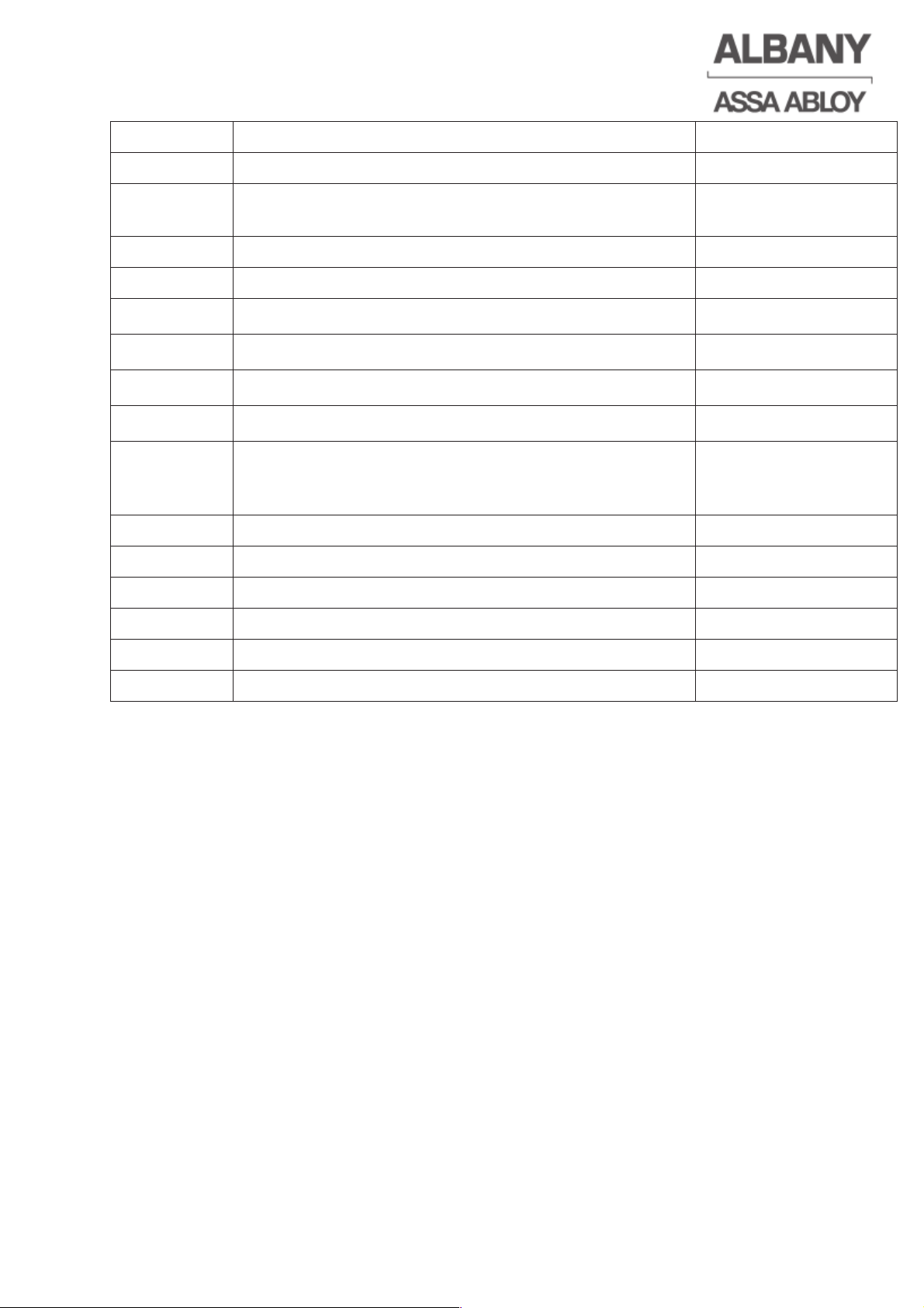
6410R0046_UM_Setup-Operation_MCC_EN11.docx 2012-07-16 69
Terminal
Description
Pin assignment
X 223 Plug-in connector for connection with the MCC
X 9 – X 21 Cable connectors for sensors/actuators parallel to the
plugs on the MCC
X 22 Alternative connector for display
X 200 Connection of the internal fuse F1 (250V T2A)
X 201 Changeover contact relay K1 - MCC output GO5/X16
1=COM, 2=NO, 3=NC
X 202 Changeover contact relay K2 - MCC output GO6/X17
1=COM, 2=NO, 3=NC
X 203 Changeover contact relay K3 - MCC output GO7/X18
1=COM, 2=NO, 3=NC
X 204 Changeover contact relay K4 - MCC output GO8/X19
1=COM, 2=NO, 3=NC
X 208 interconnection terminal block with 14 terminals
Terminals X208a and X208b are individually bridged
internally!
X209– X211 Supply terminals 24V DC for external loads
X212 - X214 Slot for plug-in radio receiver
X 215 Slot for loop detector 1 channel / 2 channel
X 216 Terminal for loop 1 (twist loop wire up to the terminal!)
X 217 Terminal for loop 2 (twist loop wire up to the terminal!)
Earth Terminal for protective earth connection
8.3.3 Plug-on modules for MCC extension
The MCC extension enables various plug-on modules for radio receivers and loop
detectors to be directly installed. All slots provided for this are specially designed for
the described plug-on modules. Plugging in other modules can cause damage or
destruction of the MCC control system, the extension as well as the add-on modules.
The plug-on modules may only be plugged in or pulled off if the control system is
switched off (disconnected from the power supply).
The respective plug-on modules can only be attached to the corresponding slot and
only in one direction on the extension. If it is necessary to remove a plug-on module
from the socket, this is made easier by alternately tilting the module.
Page 70
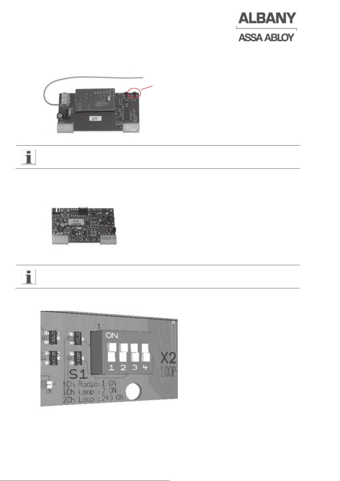
8.3.3.1 Radio receiver 433 MHz
2 channel 433 MHz radio receiver, whereby only one channel is used on the MCC
extension.
Teaching-in of the radio receiver:
Press teach in button of radio receiver and then
actuate transmitter.
Up to 32 transmitter can be teached-in
To delete the teached-in transmitter press
teach-in button until LED lights up!
Observe manual of the radio receiver!
8.3.3.2 Loop detectors
Loop detector 1 channel / 2 channel as actuators for the detection of vehicles.
8.3.3.3 Setting the slide switches for plug-on modules
Observe the manual of the loop detectors!
6410R0046_UM_Setup-Operation_MCC_EN11.docx 2012-07-16 70
Page 71
WARNING
Risk of personal injury and material damage. Disturbance of the general operation
and unexpected behaviour of the door.
The inputs and outputs of the extension board and the MCC are interconnected
parallel. A simultaneous use of the inputs and outputs can lead to a
disturbance of the general operation and unexpected behaviour of the door.
Ö The appropriate inputs to the MCC and the extension board should not be used
for other impulse actuators when using the plug-on modules.
Ö Observe electrical drawing of the door.
Ö Double assignment according to order-related electrical drawing is allowed.
Radio receiver 1 channel
Switch slide switch 1 to ON position!
With the switching on of dip switch 1, input GI8 (X19) of the MCC is in use and can
be used for other impulse actuators in exceptional cases only.
Loop detector 1 channel
Switch slide switch 2 to ON position!
With the switching on of dip switch 2, input gi7 (x18) of the MCC is assigned and can
be used for other impulse actuators in exceptional cases only.
Loop detector 2 channel
Switch slide switches 2 and 3 to ON position!
With the switching on of dip switches 2 and 3, the inputs GI6 and GI7 (X17,X18) of
the MCC are assigned and can be used for other impulse actuators in exceptional
cases only.
Slide switch 4 does not have any function!
8.4 Uninterruptible power supply (UPS)
The UPS is a unit that gives the door control system power in case of a main power
failure. The UPS is designed especially for MCC and is connected directly to the DClink circuit to guarantee the efficient and reliable function of the UPS. The MCC
controls the UPS.
In case of a main power failure the door can be operated several times immediately
after the failure. Alternatively it is one time up to 4 hours with the UPS in idle mode.
(Precondition: the batteries have to provide the specified capacity)
For efficiency reasons the door will operate with reduced speed in UPS mode of
approx. 20Hz / 0,3m/s, depending on door type.
6410R0046_UM_Setup-Operation_MCC_EN11.docx 2012-07-16 71
Page 72
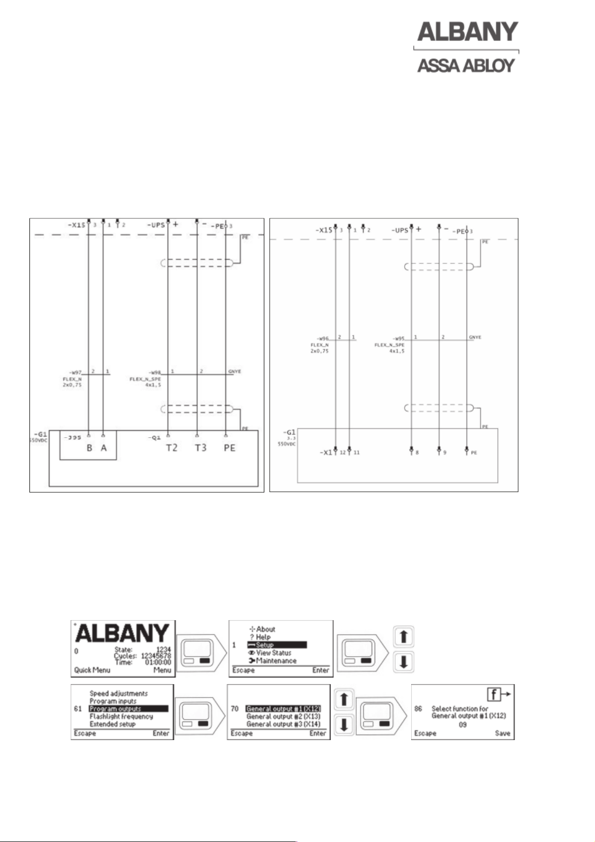
6410R0046_UM_Setup-Operation_MCC_EN11.docx 2012-07-16 72
8.4.1 Wiring the UPS to the MCC
The wiring of the door is done according to the electrical drawing. If there is no
electrical drawing available, the connections can be made according to the following
examples.
Programmable outputs X14-X19 of the MCC can be chosen to control the UPS. In
the examples of the two versions the output X15 of the MCC controls the UPS .
The UPS supply cable is to be connected to the two 6,3mm (1/4”) flat connectors
marked with UPS+ and UPS- in the MCC.
8.4.2 Parameterisation of the MCC
Activating the UPS function requires two settings to be modified. The UPS control
signal shall be programmed on a programmable output and the UPS function shall be
set in the MCC.
8.4.2.1 Programming an output to give a control signal to the UPS
Select the output to be programmed (according electrical drawing) and enter function
code 72.
Page 73
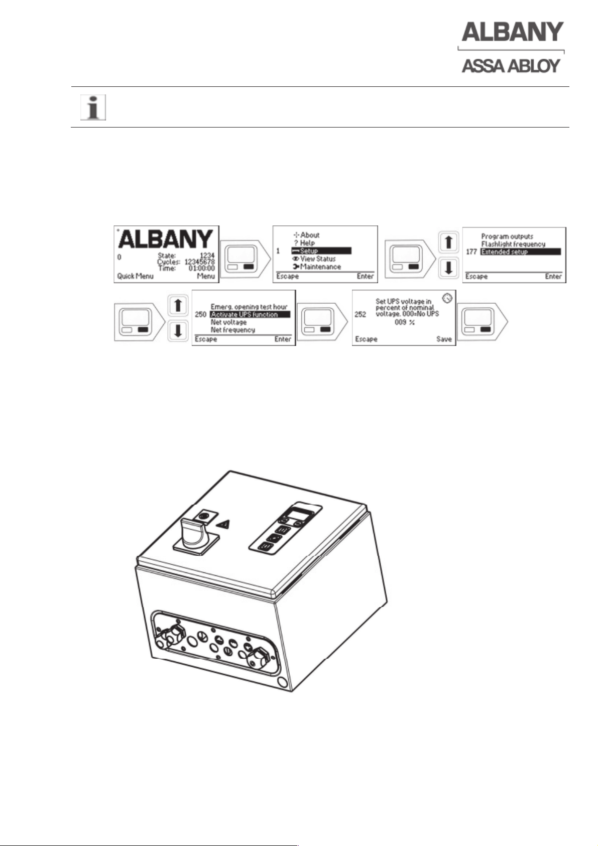
6410R0046_UM_Setup-Operation_MCC_EN11.docx 2012-07-16 73
The programmable outputs 1 and 2 (X12 and X13) are reserved for safety devices
and therefore cannot be used for controlling the UPS.
8.4.2.2 Configure the MCC for the UPS function
The UPS function needs to be activated in the MCC. It is done by adjusting the UPS
voltage in relation to the nominal net voltage in percentage. When no UPS is
connected is this value adjusted to 0%. Normal value with the UPS connected is
100%.
8.5 Single-Phase Combibox
By the use of the “single phase” combibox the MCC can be operated at single-phase
main supplies.
The operation of several doors at one phase should be avoided due to the high
current load of the single-phase supply. The main supply should be accordingly
dimensioned. Recommended is a cross-sectional area of min. 2.5 mm
2
.
The wiring of the "single phase” combibox has to be done according to the electrical
drawing.
Page 74
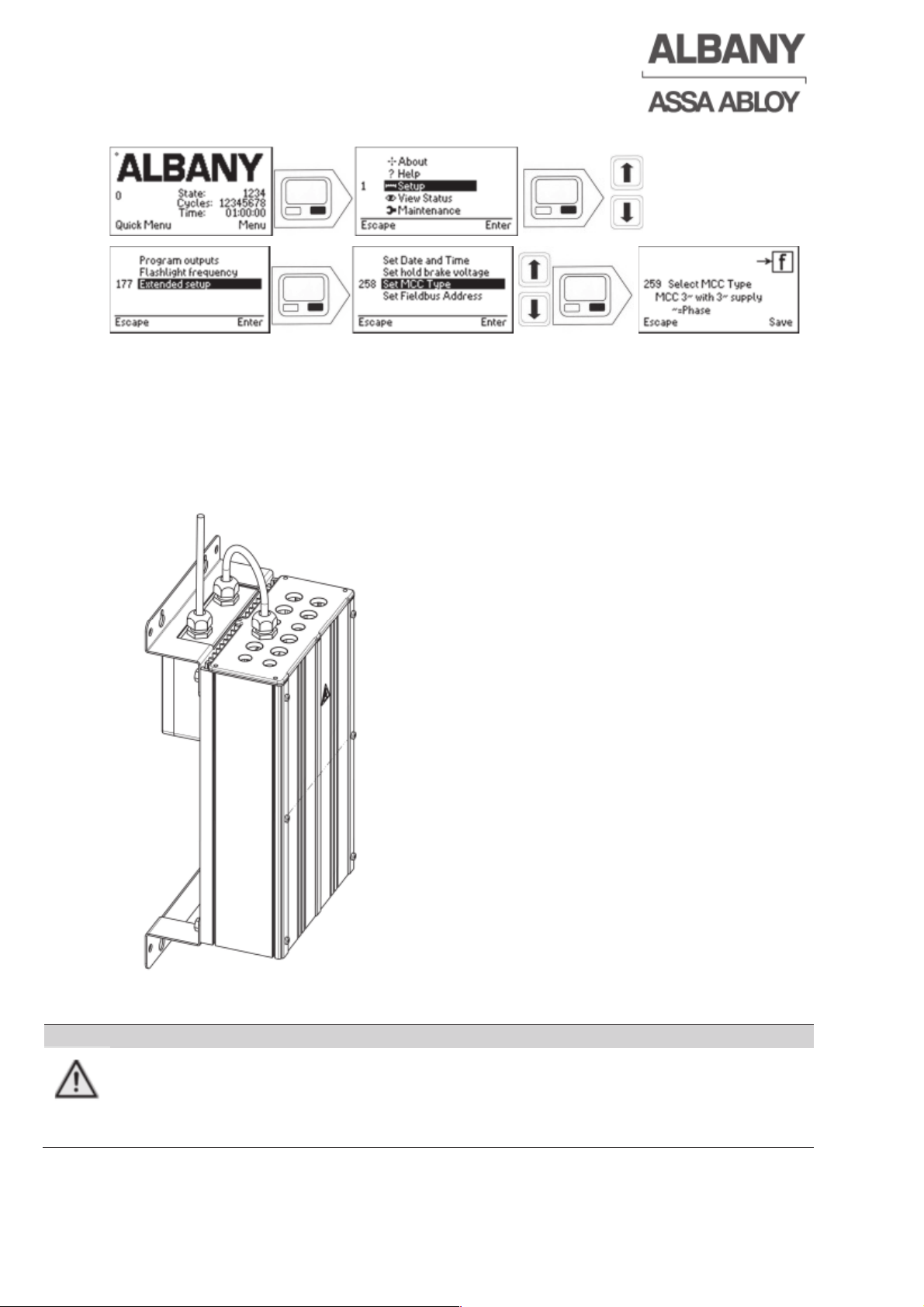
6410R0046_UM_Setup-Operation_MCC_EN11.docx 2012-07-16 74
8.5.1 Parameterisation of the MCC for single phase main supply
8.6 EMC filter
For motor cable length from 2m to 30m a EMC filter is necessary, in order to keep the
EMC requirements for the industrial and residential / commercial environments.
The EMC filter is in a separate housing and mounted below the MCC. Electrical
wiring is to be made between MCC and the main supply. Observe the electrical
drawing of the door.
CAUTION
Loss of the CE conformity.
Without EMC filters the requirements of the European EMC directive are not
kept and it may come to disturbances of other electrical devices.
Ö EMC filter is required for motor cable length larger than 2 m.
Page 75
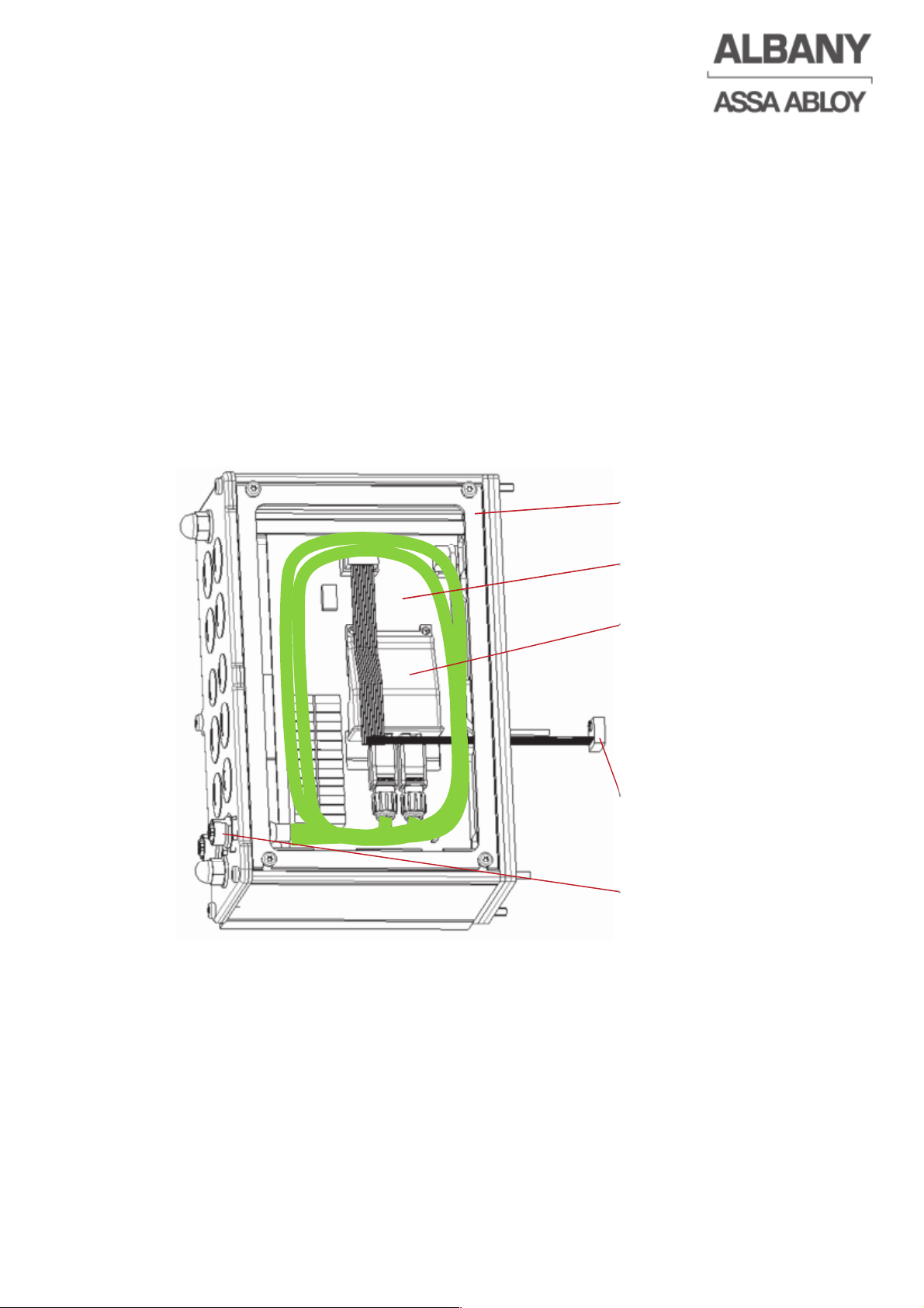
6410R0046_UM_Setup-Operation_MCC_EN11.docx 2012-07-16 75
8.7 Field bus module
The field bus module of the MCC offers the possibility to connect the MCC to
different field bus systems. The corresponding fieldbus standard is set by selecting
the used Anybus Compactcom (Anybus-CC) communication module.
8.7.1 Structure of field bus module
The fieldbus module consists of a mainboard, an Anybus CC communication module
and the MCC extension housing, which is flanged at the MCC.
The communication of the field bus module with the MCC control system is done by a
10 pole flat cable. The 24 V supply is from the MCC and is to be connected to the
plug X2 of the mainboard.
Depending on the field bus system the connection to the field bus is done by a M12
female or male plug which are installed in the flange-plate.
Figure 3: Field bus module with Profinet 2-Port
MCC – extension housing
Mainboard
Anybus CC communication
module
MCC interconnection
Field bus interconnection
Page 76
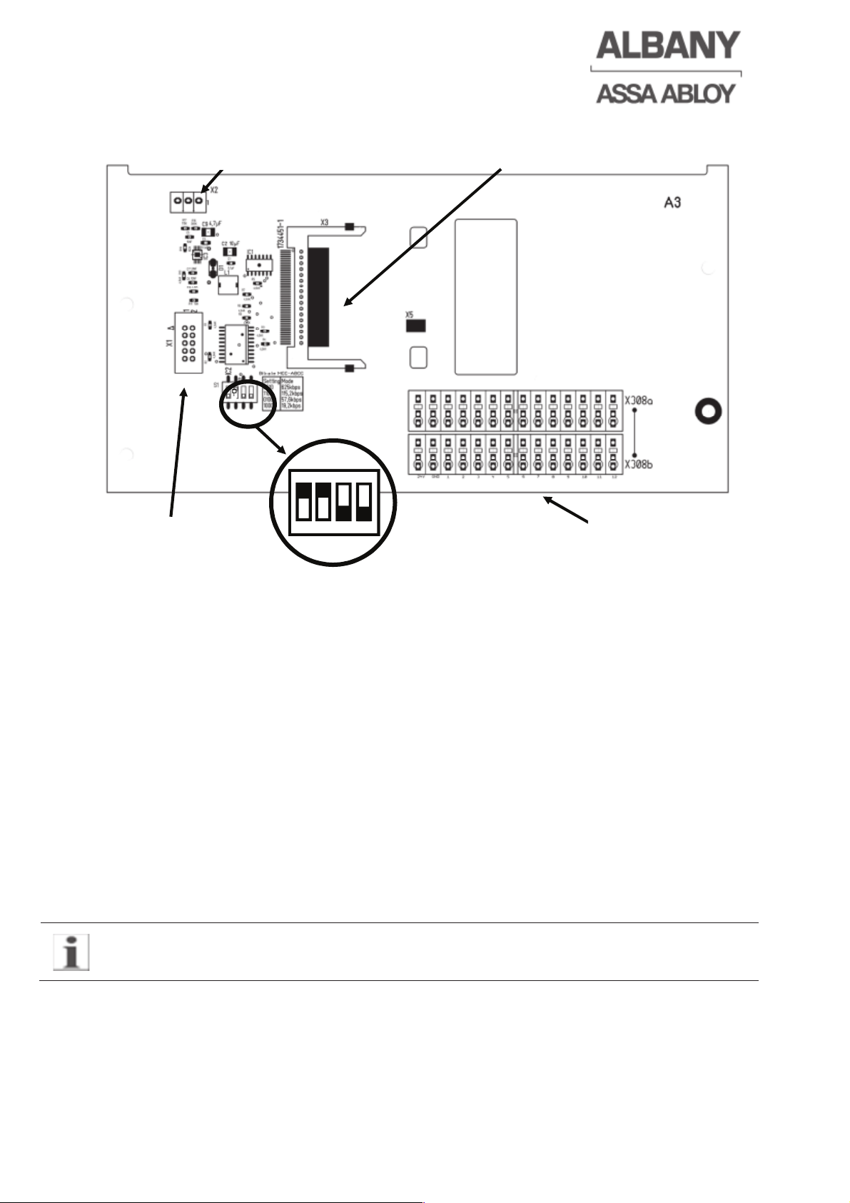
8.7.1.1 Mainboard
The DIP-switches on the mainboard for the transfer rate between MCC and bus
module should be always set to 115,2 kbps (1100).
8.7.1.2 Profinet 1-Port
For the Profinet 1-port bus structure an external network-switch is necessary.
For this solution the connection to the field bus is done via the flange plate with the
integrated M12 female plugs (D-coded).
8.7.1.3 Profinet 2-Port
The network-switch for the Profinet 2-port bus structure is integrated in the bus
module. With this solution the connection to the field bus is done via the flange plate
with the two integrated M12 female plugs (D-coded).
8.7.1.4 Profibus
For the Profibus structure the connection to the field bus is done via the flange plate
with the two integrated M12 female/male plugs (B-coded). The bus termination on
both ends for the Profibus can be turned on and off with the switch in the 9-pole DSub connector.
With the activation of the bus termination the outgoing cable is disconnected at the
plug!
The in- and outputs on the plug are marked with arrows. The female plug in the
flange plate is for the incoming cable and the male plug for the outgoing cable.
A valid address range from 0 to 125 is possible. The address 126 is reserved for the
SSA (Set Slave Address) function.
Connector for
MCC interconnection
Terminal block for
Safety relay
Slot for Anybus CC module
Connector for supply voltage
6410R0046_UM_Setup-Operation_MCC_EN11.docx 2012-07-16 76
Page 77
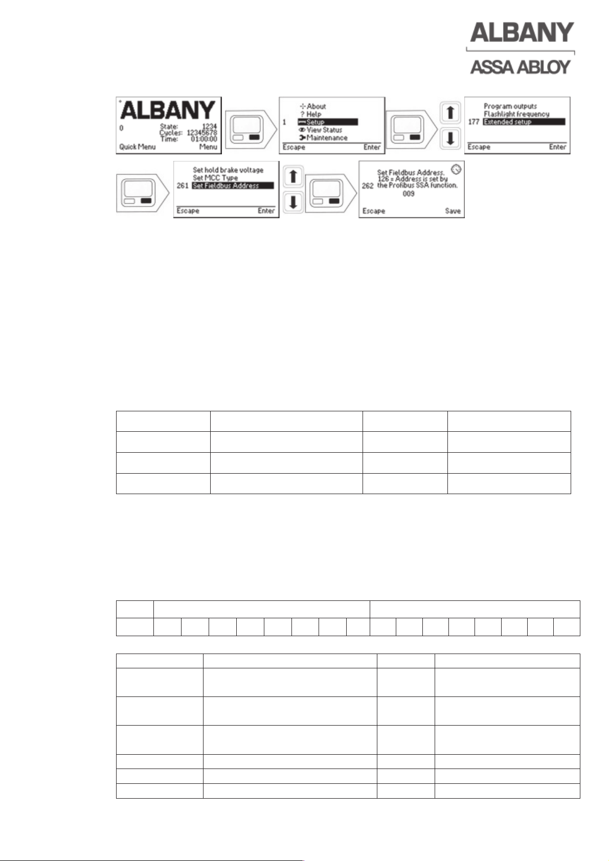
8.7.2 Set Fieldbus Address
8.7.3 Generic Station Description (GSD-file)
The Generic Station Description (GSD-file) of the used bus module can be
downloaded at http://www.anybus.com/products/abcc.shtml.
The user manual and the specifications of the manufacturer must be observed.
8.7.4 Ethernet/IP
The TCP/IP configuration setup can be made with the Anybus IP config Utility for
module TCP/IP configuration. The utility as well as the EDS file can be downloaded
from http://www.anybus.com/products/abcc.shtml.
8.7.4.1 Setup of the Ethernet/IP-Master
The settings shall be done according to the table below, which conforms to the
information in the EDS file. These terms are also used in the RSLogix 5000.
Assembly Instance Size Format
Input 100 2 16 bit
Output 150 2 16 bit
Configuration 5 0 8 bit
8.7.5 Bus communication
The cyclic write and read process data, in Profibus and Profinet called IO data will be
mapped in to so call ADI’s, application data instances. These are 16bit unsigned
variables that can also be used for acyclic data when mapped so.
8.7.6 TX data from the MCC
8.7.6.1 Application Data Instance ADI[0]
Byte
2 1
Bit 16 15 14 13 12 11 10 9 8 7 6 5 4 3 2 1
Bit position
Rules
Value
Comment
1: Door ready
for work
0: Not ready
1: Ready
0x0001
2:Door is
closed
0: Door is not closed
1: Door is closed
0x0002
3: Door is
open
0: Door is not open
1: Door is open
0x0004
4 For future use 0x0008
5 For future use 0x0010
6 For future use 0x0020
6410R0046_UM_Setup-Operation_MCC_EN11.docx 2012-07-16 77
Page 78
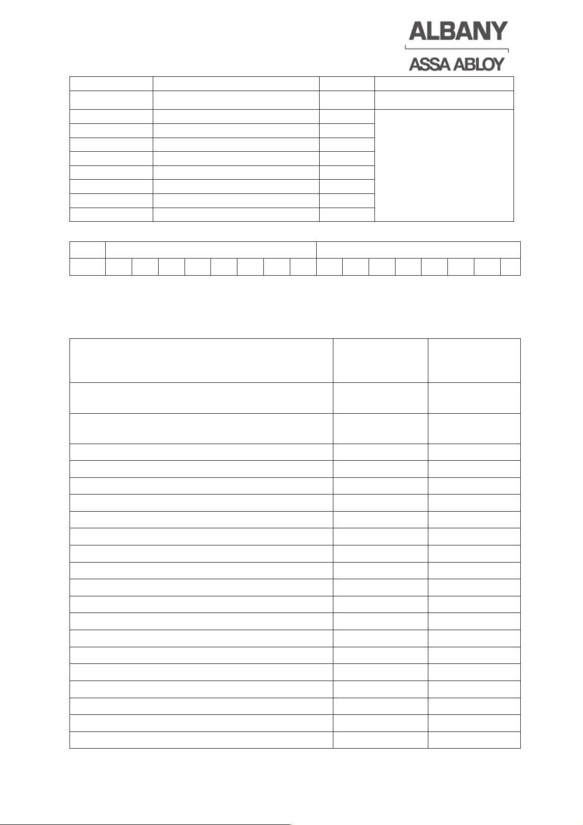
6410R0046_UM_Setup-Operation_MCC_EN11.docx 2012-07-16 78
7 For future use 0x0040
8 For future use 0x0080
9: Custom 1 0x0100
Custom1-8: For
customized digital data
out from the MCC (see
electrical drawing).
10: Custom 2 0x0200
11: Custom 3 0x0400
12: Custom 4 0x0800
13: Custom 5 0x1000
14: Custom 6 0x2000
15: Custom 7 0x4000
16: Custom 8 0x8000
8.7.6.2 Application Data Instance ADI[1]
Byte
2 1
Bit 16 15 14 13 12 11 10 9 8 7 6 5 4 3 2 1
The ADI[1] data contains a 16 bit unsigned value of the current state of the MCC
door controller. These data can be used for detecting normal operation states and for
the error messages. A list of all the error states follows below.
8.7.6.3 Allocation of the MCC error messages
MCC error messages
Decimal error
state number
Hexadecimal
error state
number
Electrical safety edge / pre-running photocell
interrupted
1004 3EC
Electrical safety edge or the pre-running
photocell activated
1005 3ED
Thermal contact tripped 1006 3EE
Encoder gives incorrect signals 1009 3F1
Encoder registers unauthorised movement 1010 3F2
Emergency lever/hand crank actuated 1011 3F3
Reference limit switch circuit interrupted 1013 3F5
Crash sensor has tripped 1015 3F7
Emergency stop actuated (X7) 1016 3F8
Safety 1 defect 1018 3FA
Door line photocell interrupted 1019 3FB
Safety 2 defect 1022 3FE
Internal frequency converter error 1023 3FF
Safety edge interrupted 1024 400
Internal error 1025 401
Reference limit switch interrupted 1026 402
Error in safety edge input 1027 403
Error in emergency stop input 1028 404
Input voltage at emergency stop input too high 1029 405
Earth fault in the 24 V circuit (low voltage) 1030 406
Page 79
Earth fault in the 24 V circuit (high voltage) 1031 407
Opening height not reached during cyclical self-
test (only for RR300 Plus F+R)
1032 408
Breakaway function activated 1033 409
Frequency converter undervoltage 1100 44C
Frequency converter phase error 1101 44D
Frequency converter overvoltage 1102 44E
Frequency converter overvoltage warning 1103 44F
Frequency converter error, wrong main voltage 1104 450
Frequency converter overcurrent 1105 451
Frequency converter error, motor blocked 1106 452
Frequency converter error, IGBT overload 1108 454
Frequency converter error, wrong hardware 1110 456
Frequency converter error, brake circuit
overcurrent
1112 458
3 phase error, frequency converter 1115 45B
Electrical safety edge or pre-running photocell
activated
1200 4B0
8.7.6.4 Byte order Profibus and Profinet IO
Both are MSB (Most Significant Byte) first buses, so the byte order is:
Byte 1 Custom data from the MCC (chapter 8.7.6.1)
Byte 2 Standard data from the MCC (Door is open etc.) (chapter 8.7.6.1)
Byte 3 MSB of the current MCC state (chapter 8.7.6.2)
Byte 4 LSB (Least Significant Byte) of the current MCC state (chapter 8.7.6.2)
8.7.7 RX data, data to the MCC
8.7.7.1 Application Data Instance ADI[2]
Byte 2 1
Bit 16 15 14 13 12 11 10 9 8 7 6 5 4 3 2 1
Bit position
Rules
Value
Comment
Reset
1: Open door
(UP)
0: NOP
1: Open the
door
0x0001 Lost bus communication
or the Anybus module is
in faulty
2:Stop door
(Stop)
0: NOP
1: Stop the
door
0x0002 Lost bus communication
or the Anybus module is
in faulty
3: Close the
door (close)
0: NOP
1: Close the
door
0x0004 Lost bus communication
or the Anybus module is
in faulty
4: Open the
door to
reduced
height
0: NOP
1: Open the
door to
reduced height
0x0008 Lost bus communication
or the Anybus module is
in faulty
6410R0046_UM_Setup-Operation_MCC_EN11.docx 2012-07-16 79
Page 80
5 Reset
system
0: NOP
1: The system
will be reset
0x0010 This bit is used to reset
the control from error
states. This bit shall
only be active for a
maximum time of
500ms to avoid that
the control is restarted
several times.
Lost bus communication
or the Anybus module is
in faulty
6 For future use 0x0020
7 For future use 0x0040
8 For future use 0x0080
9: Custom 1 0x0100
Custom1-8: For
customized digital data
in to the MCC (see
electrical drawing)
Custom1-8: Lost bus
communication or the
Anybus module is in
faulty
10: Custom 2 0x0200
11: Custom 3 0x0400
12: Custom 4 0x0800
13: Custom 5 0x1000
14: Custom 6 0x2000
15: Custom 7 0x4000
16: Custom 8 0x8000
8.7.7.2 Application Data Instance ADI[3]
Byte
2 1
Bit 16 15 14 13 12 11 10 9 8 7 6 5 4 3 2 1
Bit Pos.
Rules Value Reset
1 For future use 0x0001 Lost bus communication or the
Anybus module is in faulty
2 For future use 0x0002
3 For future use 0x0004
4 For future use 0x0008
5 For future use 0x0010
6 For future use 0x0020
7 For future use 0x0040
8 For future use 0x0080
9 For future use 0x0100
10 For future use 0x0200
11 For future use 0x0400
12 For future use 0x0800
13 For future use 0x1000
14 For future use 0x2000
15 For future use 0x4000
16 For future use 0x8000
6410R0046_UM_Setup-Operation_MCC_EN11.docx 2012-07-16 80
Page 81
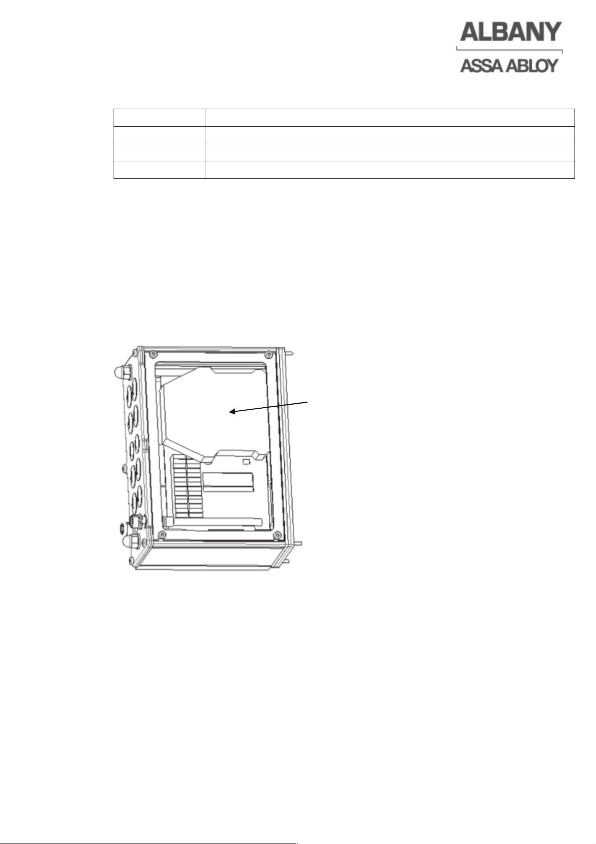
8.7.7.3 Byte order Profibus and Profinet IO
Both are MSB (Most Significant Byte) first buses, so the byte order is:
Byte 1 Custom data to the MCC (chapter 8.7.7.1)
Byte 2 Standard data to the MCC (Door open etc.) (chapter 8.7.7.1)
Byte 3 For future uses (chapter 8.7.7.2)
Byte 4 For future uses (chapter 8.7.7.2)
8.7.8 Installation of the safety relays (Option for machine protection doors)
Additional to the bus module it is possible to mount a safety relay for the safety limit
switches at the machine protection door in the MCCC extension box. This relay is
snapped on the DIN rail of the MCC adapter plate. The wiring is done via the terminal
blocks X308a and b on the mainboard.
Safety relay
6410R0046_UM_Setup-Operation_MCC_EN11.docx 2012-07-16 81
Page 82

www.albanydoors.com
6410R0046_UM_Setup-Operation_MCC_EN11.docx 2012-07-16 82
 Loading...