

Page 1
345 Bayview Avenue
Amityville, New York 11701
For Sales and Repairs 1-800-ALA-LOCK
For Technical Service 1-800-645-9440
or visit us at http://tech.napcosecurity.com/
(Note: Technical Service is for security professionals only)
Publicly traded on NASDAQ Symbol: NSSC
© ALARM LOCK 2015
MODEL PG30 Pilfergard Door Alarm
Installation Instructions
WI739E 02/15
DESCRIPTION
The PG30 is a keypad operated surface-mounted micropro-
cessor-controlled door alarm. Three programmable security
levels provide degrees of access to suit various applications,
such as unattended fire stairways, airport security areas, delivery entrances, etc. The unit contains a Form-C relay as
well as provisions for an external power supply and external
reed-switch contacts.
The unit mounts on the door with a magnetic actuator on the
frame, or, if external wiring is required, vice versa. Entering
the Master Code will alternately arm and disarm the unit. A
selectable Annunciator feature beeps to signal opening of the
door while the unit is disarmed. Opening the door, removing
the cover or attempting to defeat the unit with a second magnet when armed, will activate the alarm. The unit may be operated from outside the door with the addition of a model
PG30KPD External Keyp ad (option al).
SPECIFICATIONS
Dimensions: 9" x 2½" x 2⅜" (22.8cm x 6.3cm x 6.8cm)
(LxWxD)
Finish: Metallic Silver (PG30MS); Metallic Bronze
(PG30MB)
Power Requirements: 9-volt alkaline battery (supplied). (The
PG30 may be used with Model PP100 (optional) or other
power supply providing 9-12VDC at 500mA).
Battery Life: Continuous Alarm, 3 hours; 2-Minute Shut-
down, see Table 1 below.
Alarms / Year Battery Life (Months)
1 17.6
2 17.4
3 17.1
4 16.8
5 16.6
6 16.3
7 16.1
8 15.8
9 15.6
10 15.4
Table 1. Battery Life with 2-Minute Shutdown option.
Sounding Device: Piezo electronic sounder, sweep siren,
110dB at 10 feet.
Shipping Weight: 1lb., 10oz.
FEATURES
Three codes: Master, Management and Passage
Three levels of security to suit different applications
Three alarm types: Sweep, steady or pulsing siren
Two Annunciator volume levels
Automatic low-battery detection
Provisions for external power supply
Provisions for external reed-switch contacts for multiple-
door monitoring
Built-in Form-C relay for connection to control panel or
other device
INSTALLATION
Note: In many applications, the need for a template may
be eliminated by using the Magnet Alignment procedure in
step 10. If outside keypad control or remote wiring is required,
however, the template must be used.
1. If using a template, select the proper template for the type
of door. (If not using a template, proceed to step 6).
2. Mark and drill 9/64" holes per template directions on the
door and jamb. (Four holes for base plate and two holes
for magnetic actuator). Note: Certain narrow-stile doors
require only two holes for mounting plate.
3. Mark and drill ⅜" hole per template for remote wiring to a
control panel.
4. For outside keypad control only: Drill ¾" hole as
shown on template. Refer to the PG30KPD instructions
for installation of outside keypad.
5. Knock out the necessary holes from the base plate and
install on the door with #8 sheet-metal screws (supplied).
If an outside keypad is used, ensure that its cable is routed through the hole in the base plate.
6. Connect the battery (a chirp will sound; this chirp will con-
firm that power is connected properly). Important: Press
the small CLEAR button at the lower-left corner of the
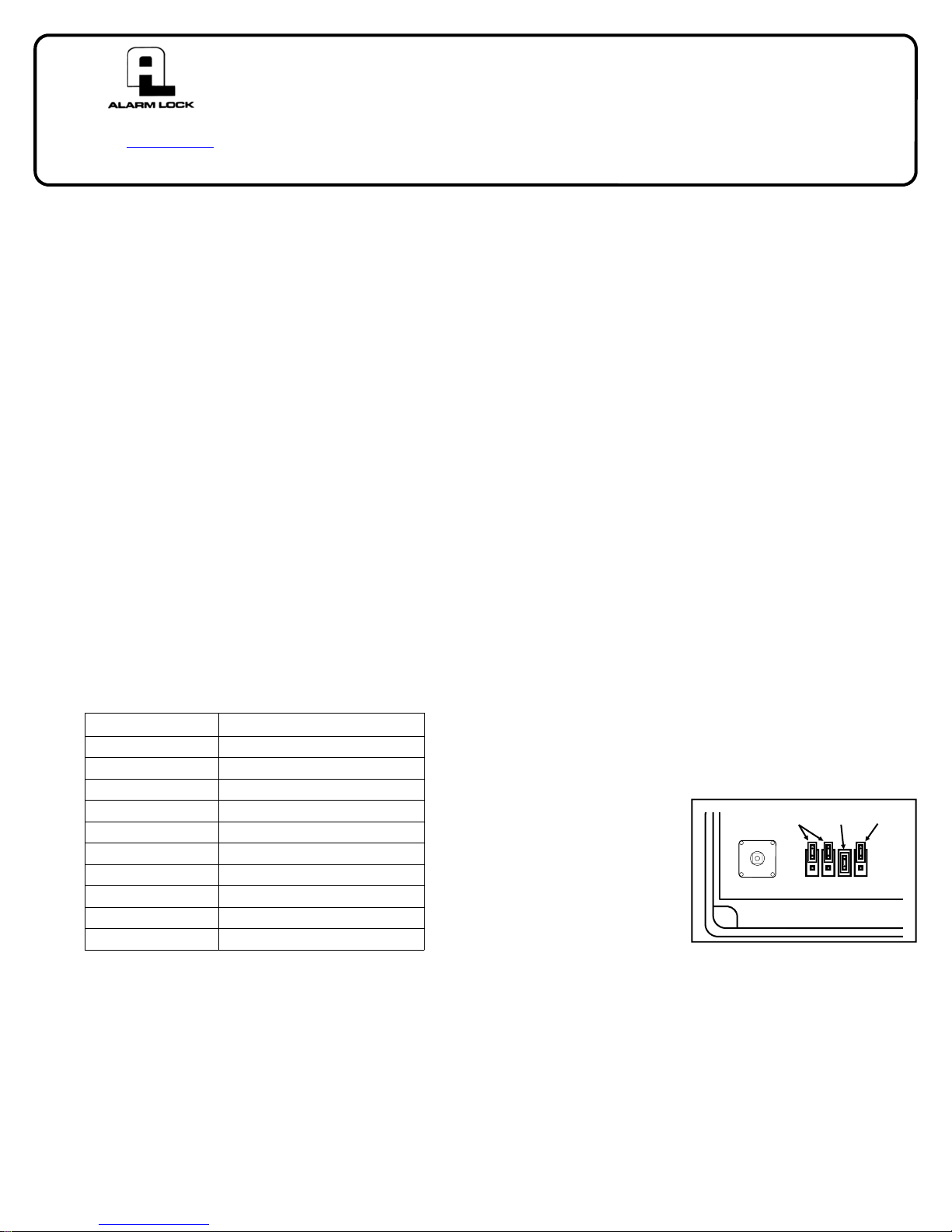
circuit board (see Fig. 1).
7. Remove the jumper ONLY on the side of the unit that the
magnet will NOT be installed.
8. Select jumper options (J1 - J4) as follows: Refer to Fig. 1;
OFF
ON
OFF
the unit is factory
supplied with the
Annunciator option
enabled (J3 installed)
and 2-Minute Shutdown alarm selected
(J4 removed).
CLEAR
Fig 1. CLEAR Button and Jumpers
1 2 3 4
Important: Changes in the jumper configuration do
not become effective until the unit is subsequently armed.
J1: Entry Delay. Alarm will sound 15 seconds after any
unauthorized entry through door if unit is armed. This
feature is used for authorized entry. To avoid an alarm
upon entry, disarm unit within 15 seconds. To enable
Entry Delay, install J1 across both pins.
J2: Exit Delay. Unit will be activated after 15 seconds
each time unit is armed to allow authorized exit without
an alarm. To enable Exit Delay, install J2 across both
pins.
1
Page 2
J3: Annunciator. Unit will sound for 2 seconds when-
ever the door is opened while disarmed. To disable
the Annunciator, remove J3.
J4: Continuous / 2-Minute Shutdown. With J4 in-
stalled, an alarm will sound continuously until the battery is depleted. With J4 removed, the alarm will silence after two minutes and the unit will rearm (if the
door is closed). The LED will start flashing to indicate
that an alarm has occurred (Alarm Memory). Alarm
Memory is cleared after about 4 hours or when the unit
is re-armed. Note: If the door is still open after two
minutes, the alarm will restart. Note: Jumper J4 is con-
nected at the factory to only one pin of the 2-pin connector (off). To select Continuous alarm, remove J4
and reinstall it across both pins.
9. Install the cover onto the base plate. Secure the cover
with #6-32 screws supplied. Note: The longest screw is
the tamper screw. If not using a template, do not install
the tamper screw until the magnet has been aligned and
secured as follows.
10. (If unit has been installed using a template, proceed to
step 11). After power-up, but before the tamper screw is
installed, the unit will be in the Magnet Alignment Mode.
a. Place the magnet against the wall, adjacent to the
bottom of the unit. Slowly slide the magnet upward.
The LED will turn on, indicating closure of the reed
switch, then the LED will turn off. Mark the doorjamb
at the bottom of the magnet. (Note: Sliding the mag-
net still further will cause the LED to light again; ignore
subsequent indications).
b. Similarly, place the magnet against the wall, adjacent
to the top of the unit. Slowly slide the magnet downward. The LED will turn on, and then will turn off once
again (see Note in step 10a). Mark the doorjamb at
the top of the magnet.
11. Install the magnetic actuator so that it is centered between the two marks on the doorjamb. Use the two #8
sheet-metal screws supplied. Note: On steel frames, it
is sometimes necessary to install a non-magnetic shim
between the magnet and the frame to prevent the steel
frame from absorbing the magnet's magnetic field, which
could cause a constant or occasional false alarm condition. The shim should be ½" x 2½" x ⅛" thick nonmagnetic material (plastic, Bakelite, rubber, etc.).
STANDBY MODE
After the magnet has been aligned and mounted, the tamper
screw may be installed. This will place the unit in its standby
mode (disarmed).
ARMING & DISARMING
The unit is alternately armed and disarmed by entering the
Master Code.
WIRING
External wiring to the PG30 requires that the unit be mount-
ed on the frame with the magnet on the adjacent door. (The
PG30 may be mounted on a door with the addition of a
Model 271 Flexible Cable). All wiring is made at its terminal
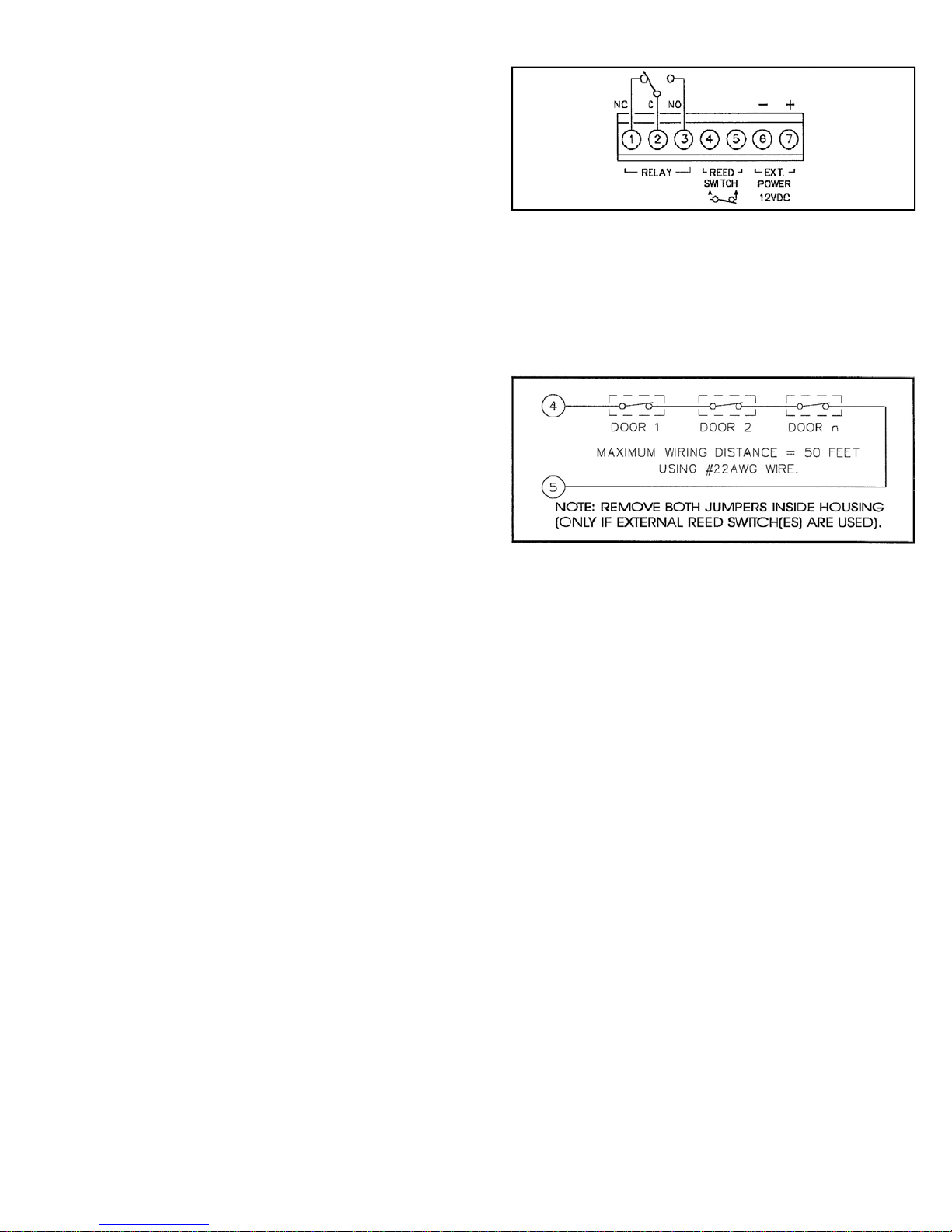
strip. Wiring connections are summarized in the Wiring Diagram shown in Fig. 2.
Relay (Terminals 1-3). Terminal 1 = Nor mally Closed;
2
Terminal 2 = Common; Terminal 3 = Normally Open.
Fig. 2. Wiring Diagram. Also see Fig. 3
Reed Switch (Terminals 4 & 5). Connect ex ternal reed-
switch contacts to Terminals 4 and 5 and remove both jump-
ers. Note: If reed switches are wired in series as shown in
Fig. 3, several doors may be monitored simultaneously. Using #22AWG wire, maximum wiring distance should not exceed 50 feet (15.24m).
Fig. 3. Multiple door monitoring
Power (Terminals 6 & 7). Connect an extern al power
supply: Positive (+) to Terminal 7; negative (–) to Terminal
6. Leave the internal battery in as a backup battery. If using
the Alarm Lock PP100 Power Supply, connect the two battery clips to the unit and the internal battery as labeled.
FIELD TEST
1. With the door closed, enter a valid arming code. A brief
tone will sound indicating that the unit is armed (with or
without delays, see options in INSTA LLATION: step 8).
2. Open the door. A sweep siren alarm should sound.
3. On alarm, the relay will activate and remain latched for as
long as the sounder is on. Relay contacts are rated at
125VAC/DC at ½A.
4. To reset the alarm, enter the Master Code or the Management Code.
BATTERY REPLACEMENT
Whether armed or disarmed, the LED will blink about once
every 4 hours when checking battery status. When the battery becomes weak, the unit will chirp and the LED will flash
about once per minute, indicating the need for replacement.
Disarm the unit before replacing battery. When battery is
disconnected, DO NOT press buttons or programming
WILL BE LOST; connect new battery as quickly as possible. Be sure the extra long Tamper Screw (see Fig. 4)
is returned to its correct location (lower left corner); failure to
replace the Tamper Screw in its correct location will render
the unit inoperable.
PROGRAMMABLE FEATURES
The following features are software programmable.
Page 3

Codes: Master, Management, and Passage Codes;
Security Level (Level 1, 2 or 3);
Alarm Type: Sweep, Steady, or Pulsing Siren; and
Annunciator Volume: Low or High.
We recommend the unit be programmed after it has been
mounted and the door closed, as the tamper switch must be
installed and the magnet properly positioned with respect to
the active reed switch. If it is desired to pre-program the unit
before mounting, keep the tamper switch closed (install tamper
screw) and the reed switch closed (place magnet near switch)
until programming is completed.
Note: (1) When entering codes or programming, each but-
ton must be pressed within 5 seconds of the last or the unit will
time out. (2) Press the [AL] button to cancel a wrong code
entry (prior to completion). (3) Seven beeps indicate that the
programmed code has been accepted. (4) Five beeps indicate either a wrong code entry or a programming error. (5)
Three unsuccessful attempts to enter a code will sound a loud
2-second alert.
CODES
Each code may be 3 to 5 digits in length.
Master Code. The Master Code can be used to program
any code or feature or to arm or disarm. The default Master
Code is 1 2 3 4 5. This default Master Code mu st be chan g ed
before any other code or function can be programmed. To
program a new Master Code, press [1] [2] [3] [4] [5] [AL] [1]
[AL] [new Master Code] [AL].
Note: Be sure to enter the new Master Code carefully. If
the wrong Code is entered and is unknown, press the CLEA R
button on the circuit board to reset the unit and erase all
codes, then start over. (Whenever the CLEAR button is
pressed, all programmed Codes are erased and the Master
Code defaults to 1 2 3 4 5).
To program the Management Code (see below), press the
Master Code, then press [AL] [2] [AL] [new Management
Code] [AL].
Management Code. The Management Code may be used
to program the Passage Code, any feature, or to silence the
alarm.
Passage Code. This code allows passage through t he
protected door without altering the arm/disarm status of the
unit. If the unit is armed, the door must be closed within 15
seconds or the alarm will sound. The Passage Code may be
used with any programmed security level.
To program the Passage Code, enter the Master Code or
Management Code, then press [AL] [3] [AL] [new Passage
Code] [AL].
SECURITY LEVELS
There are three levels of security to accommodate different
applications. Note: The tamper switch and keypad are disa-
bled until the door is closed. Security levels are programmable
using the Master Code or Management Code:
Level 1. Provides the highest level of security and is the
default mode of operation. Opening the door while armed will
cause the alarm to latch on (after the entry delay, if enabled).
The alarm may only be reset using the Master Code or the
Management Code. To re-program Level-1 security (if
changed), enter the Master Code or Management Code, then
press [AL] [3] [3] [AL].
Level 2. Entering the Passage Code will allow the door to
be opened up to 15 seconds without activating an alarm. If no
code is entered or if the door remains open longer than 15
seconds, a non-latching alarm will sound; that is, when the
door is closed, the alarm will shut down and the unit will reset.
Applications include unattended doors as may be found at fire
stairwells, airport high-security areas, etc. that must remain
closed after passage. To enable Level-2 security, first enter
the Master Code or Management Code, then press [AL] [4] [4]
[AL].
Level 3. Entering the Passage Code allows th e door to
remain open indefinitely without activating an alarm. When the
door is closed, the unit will rearm automatically. A typical application might be a delivery entrance where the door is
propped open for long periods of time. To enable Level-3 security, first enter the Master Code or Management Code, then
press [AL] [5] [5] [AL].
ALARM TYPES
Sweep Siren. This i s the def ault alarm. To r e-program a
Sweep Siren alarm (if changed), enter the Master Code or
Management Code, then press [AL] [1] [1] [AL].
Steady Siren. To program a Steady Siren alarm, enter the
Master Code or Management Code, then press [AL] [1] [2] [AL].
Pulsing Siren. To p rogram a Pulsing Siren alarm, enter the
Master Code or Management Code, then press [AL] [1] [3] [AL].
ANNUNCIATOR VOLUME
Low. This is the default setting. Low volume is adjusta-
ble by means of the potentiometer at the upper-left corner of
the circuit board; clockwise rotation increases loudness. To
reprogram Low-volume annunciator (if changed), press the
Master Code or Management Code, then press [AL] [1] [4]
[AL].
High. This setting provides maximum loudness. To pro-
gram High volume, press the Master Code or Management
Code, then press [AL] [1] [5] [AL].
EXPLODED VIEW
Fig. 4. Exploded view with part numbe rs
3
Page 4

ALARM LOCK LIMITED WARRANTY
ALARM LOCK SYSTEMS, INC. (ALARM LOCK) warrants
its products to be free from manufacturing defects in materials and workmanship for twenty four months following the
date of manufacture. ALARM LOCK will, within said period, at its option, repair or replace any product failing to
operate correctly without charge to the original purchaser
or user.
This warranty shall not apply to any equipment, or any part
thereof, which has been repaired by others, improperly
installed, improperly used, abused, altered, damaged, subjected to acts of God, or on which any serial numbers have
been altered, defaced or removed. Seller will not be responsible for any dismantling or reinstallation charges,
environmental wear and tear, normal maintenance expenses, or shipping and freight expenses required to return products to ALARM LOCK. Additionally, this warranty
shall not cover scratches, abrasions or deterioration due to
the use of paints, solvents or other chemicals.
THERE ARE NO WARRANTIES, EXPRESS OR IMPLIED, WHICH EXTEND BEYOND THE DESCRIPTION
ON THE FACE HEREOF. THERE IS NO EXPRESS OR
IMPLIED WARRANTY OF MERCHANTABILITY OR A
WARRANTY OF FITNESS FOR A PARTICULAR PURPOSE. ADDITIONALLY, THIS WARRANTY IS IN LIEU
OF ALL OTHER OBLIGATIONS OR LIABILITIES ON THE
PART OF ALARM LOCK.
Any action for breach of warranty, including but not limited
to any implied warranty of merchantability, must be
brought within the six months following the end of the warranty period.
IN NO CASE SHALL ALARM LOCK BE LIABLE TO ANYONE FOR ANY CONSEQUENTIAL OR INCIDENTAL
DAMAGES FOR BREACH OF THIS OR ANY OTHER
WARRANTY, EXPRESS OR IMPLIED, EVEN IF THE
LOSS OR DAMAGE IS CAUSED BY THE SELLER'S
OWN NEGLIGENCE OR FAULT.
In case of defect, contact the security professional who
installed and maintains your security system. In order to
exercise the warranty, the product must be returned by the
security professional, shipping costs prepaid and insured
to ALARM LOCK. After repair or replacement, ALARM
LOCK assumes the cost of returning products under warranty. ALARM LOCK shall have no obligation under this
warranty, or otherwise, if the product has been repaired by
others, improperly installed, improperly used, abused, altered, damaged, subjected to accident, nuisance, flood,
fire or acts of God, or on which any serial numbers have
been altered, defaced or removed. ALARM LOCK will not
be responsible for any dismantling, reassembly or reinstallation charges, environmental wear and tear, normal
maintenance expenses, or shipping and freight expenses
required to return products to ALARM LOCK. Additionally,
this warranty shall not cover scratches, abrasions or deterioration due to the use of paints, solvents or other chemicals.
This warranty contains the entire warranty. It is the sole
warranty and any prior agreements or representations,
whether oral or written, are either merged herein or are
expressly cancelled. ALARM LOCK neither assumes, nor
authorizes any other person purporting to act on its behalf
to modify, to change, or to assume for it, any other warranty or liability concerning its products.
In no event shall ALARM LOCK be liable for an amount in
excess of ALARM LOCK's original selling price of the
product, for any loss or damage, whether direct, indirect,
incidental, consequential, or otherwise arising out of any
failure of the product. Seller's warranty, as hereinabove set
forth, shall not be enlarged, diminished or affected by and
no obligation or liability shall arise or grow out of Seller's
rendering of technical advice or service in connection with
Buyer's order of the goods furnished hereunder.
ALARM LOCK RECOMMENDS THAT THE ENTIRE SYSTEM BE COMPLETELY TESTED WEEKLY.
Warning: Despite frequent testing, and due to, but not
limited to, any or all of the following; criminal tampering,
electrical or communications disruption, it is possible for
the system to fail to perform as expected. ALARM LOCK
does not represent that the product/system may not be
compromised or circumvented; or that the product or system will prevent any personal injury or property loss by
burglary, robbery, fire or otherwise; nor that the product or
system will in all cases provide adequate warning or protection. A properly installed and maintained alarm may
only reduce risk of burglary, robbery, fire or otherwise but
it is not insurance or a guarantee that these events will not
occur. CONSEQUENTLY, SELLER SHALL HAVE NO LIABILITY FOR ANY PERSONAL INJURY, PROPERTY
DAMAGE, OR OTHER LOSS BASED ON A CLAIM THE
PRODUCT FAILED TO GIVE WARNING. Therefore, the
installer should in turn advise the consumer to take any
and all precautions for his or her safety including, but not
limited to, fleeing the premises and calling police or fire
department, in order to mitigate the possibilities of harm
and/or damage.
ALARM LOCK is not an insurer of either the property or
safety of the user's family or employees, and limits its liability for any loss or damage including incidental or consequential damages to ALARM LOCK's original selling price
of the product regardless of the cause of such loss or
damage.
Some states do not allow limitations on how long an implied warranty lasts or do not allow the exclusion or limitation of incidental or consequential damages, or differentiate in their treatment of limitations of liability for ordinary or
gross negligence, so the above limitations or exclusions
may not apply to you. This Warranty gives you specific
legal rights and you may also have other rights which vary
from state to state.
4
 Loading...