


|
|
|
|
|
DL1300 |
|
|
|
|
|
|
Programming Instructions |
|
||
|
|
345 Bayview Avenue |
|
||||
|
|
Amityville, New York 11701 |
|
|
|
||
For Sales and Repairs 1-800-ALA-LOCK |
|
|
|
||||
For Technical Service 1-800-645-9440 |
|
|
OI311 7/06 |
||||
|
|
© ALARM LOCK 2006 |
|
Publicly traded on NASDAQ Symbol: NSSC |
|
||
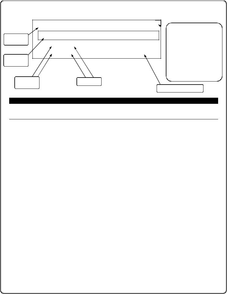
AL-IR1 PRINTER
AL-DTM
DATA TRANSFER
MODULE
DL-WINDOWS PROGRAMMING
SOFTWARE
DL1300
DL Trilogy Series
Stand-Alone Access Control Systems
1
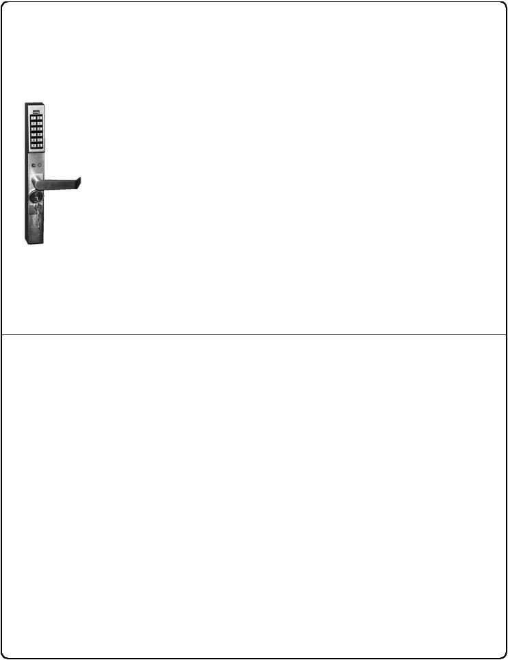
DL1300 SERIES LOCK
THE ALARM LOCK TRILOGY DL1300 SERIES STAND-ALONE ACCESS CONTROL SYSTEM IS A STATE- OF-THE-ART MICROPROCESSOR-BASED PROGRAMMABLE KEYPAD-ENTRY SECURITY LOCK.
DL1300
Your new DL1300 Alarm Lock Trilogy electronic digital lock is a mortisebased manually programmable narrow stile entry trim for Adams Rite®
4710, 4730 and 4900 deadlatch locks, and 1850, 1950, 4070, MS1850S and MS1950S series deadbolts for narrow stile aluminum doors*.
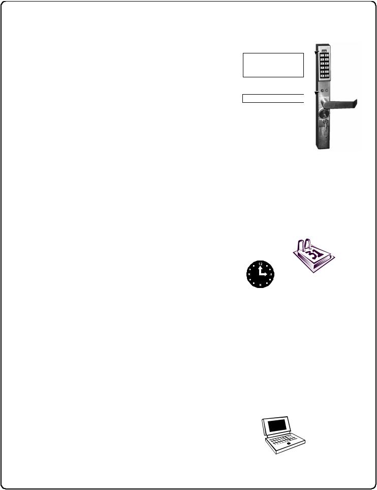
Features a real-time clock/calendar that automatically adjusts for Daylight Saving Time and allows for automated programming of events. Features three methods of programming: (1) all features can be programmed manually through the keypad; (2) you can transfer programming instructions directly from your laptop or desktop PC using DL-Windows software and a special AL-PCI cable; and (3) data can be transferred from your PC to your DL1300 lock via the AL DTM handheld Data Transfer Module. In
DL1300 addition, data can be retrieved from the lock in one of three ways (1) through an infrared printer; (2) directly from the lock to the PC; or (3) through an AL-DTM to your PC.
*Adams Rite Manufacturing Co., Pomona, CA. www.adamsrite.com
All products, product names and services described in this manual are for identification purposes only and may be trademarks of their respective companies.
Table of Contents
DL1300 Series Lock Features |
3 |
.......................................Testing the Codes Entered |
13 |
|
|
||
Supported Products |
4 |
Programming Functions Overview......................... |
14 |
|
|
||
Lock Design Overview |
5 |
Programming Functions..................................... |
15-26 |
|
|
||
Terminology Used in this Manual |
6 |
Groups and Scheduled Group 1 Examples........... |
27 |
|
|
||
Programming Levels |
8 |
Programming Record Sheet..................................... |
29 |
|
|
||
Conventions Used in this Manual |
9 |
User Code Record Sheet .................................... |
30-32 |
|
|
||
LED and Sounder Indicators |
9 |
Schedule Record Sheet ...................................... |
33-34 |
|
|
||
Product Communication Examples |
10 |
Glossary ...................................................................... |
35 |
|
|
||
Wiring and Power Up |
11 |
Limited Warranty........................................................ |
36 |
|
|
||
Quick Start.................................................................. |
12 |
|
|
|
|
|
|
2
DL1300 Series Lock Features
Audit Trail
•40,000 Event Capacity
•Entries Logged with Time and Date
•Critical Programming Events Logged
•Printable using the AL-IR1 Hand-Held Printer (see page 22, Function 55)
•Uploadable using Alarm Lock's DL-Windows software (see page 22, Function 58)
•Transferable to AL-DTMs
Lock Features
•Metal Key Override for all cylindrical locks
•Keypad Lockout (see page 23, Functions 60-61)
•Non-Volatile (Fixed) Memory
•Real-Time Clock (within one second accuracy) (see page 20, Functions 43-44)
•Visual and Audible Keypad Feedback (see page 9)
•Battery Status Monitor (see page 9)
Scheduling
Two-Color Status LED 
& Infrared LED (for
Printer)
PC / AL-DTM Interface 
•500 Scheduled Events (see pages 24-28)
•Automated Unlock/Lock
•Enable/Disable Users (see page 16, Function 3)
•Enable/Disable Groups (see page 17)
•Four "Quick Schedules" (contains 4 most common schedules) (see page 25)
•Real-time clock and calendar (see page 19)
•Programmable Timeout Functions (see page 17-20)
User Access Methods
• Keypad Entered User Codes (see pages 12-13, 15)
•Metal Key Override
User Features
•2000 Users (see pages 12-13, 15)
•6 Pre-defined Administration User Levels including Master, Installer, Manager, Supervisor, Print-Only and Basic User Codes (see page 8)
•User Code Lengths from 3-6 digits
•Service Code (“One-Time-Only” Code) (see page 7)
•User Lockout Mode (see page 16, Function 6)
•Users Assignable to 4 Groups (see page 27)
Keypad and Computer Programming
•All programming may be performed manually from the keypad, or from a PC using Alarm Lock's DLWindows Software (see page 5)
3
Supported Products
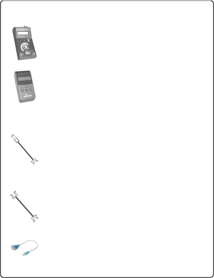
Data Transfer Module (AL-DTM)
An AL-DTM is used to transfer Lock Programs (and other data) between DL-Windows and locks. When computers cannot be transported or when electrical power is not available, the hand-held ALDTM device acts as a go-between--it allows the transfer of lock data from the computer (through the AL-DTM) and to the lock, or in reverse (from the lock through the AL-DTM back to the computer).
Infrared Printer (AL-IR1)
An AL-IR1 printer is used to print Audit Trails and User Code lists without the need for a PC. Its infrared reader means no cable connection to the lock is needed.
AL-PCI Cable
An ALARM LOCK AL-PCI cable is required to communicate between your computer’s RS-232 serial communications port (COM 1-4) and the AL-DTM or lock. One end of the AL-PCI cable is designed to be used on a 9-pin serial Com Port. If your computer has a 25-pin Com Port only, a 25-pin to 9-pin adapter must be used. The other end of the AL-PCI cable features a 2-pin banana plug connector which is polarity sensitive--the TAB (marked “GND”) side must be plugged into the lock’s black (left) terminal.
Double-ended Mini Banana Plug Connector
After you create the program in DL-Windows and transfer the program from your computer to an AL-DTM, transfer the program from the AL-DTM to the lock(s) via a double-ended mini banana plug.
USB to RS-232 Cable
If your computer does not have a serial COM port (DB-9 male) available, you can plug your ALPCI2 cable into a special USB to RS-232 cable. Order part PCI-USB for the USB to RS-232 cable only, or ALPCI2-U for both the USB to RS-232 cable and an AL-PCI2 cable).
4
Lock Design Overview
Why Use Software inside a Lock?
With ordinary door locks, the need to make physical copies of metal keys and distributing them can be a huge organizational and financial task -- and what will you do if someone causes a security breach by simply losing their key?
The answer lies in the advantage of software. Software (also called "firmware") is not "hard" or "fixed" like hardware is. Software is "soft" -- flexible and changeable to your needs. Software exists inside your Alarm Lock™ series lock, and can be programmed (and re-programmed again and again) to suit your changing requirements. No more metal keys to distribute...instead, distribute User Codes -- and delete them from the software when needed. (A User Code is the software equivalent of a metal key--it is a series of numbers the User enters into the door lock keypad to unlock the lock).
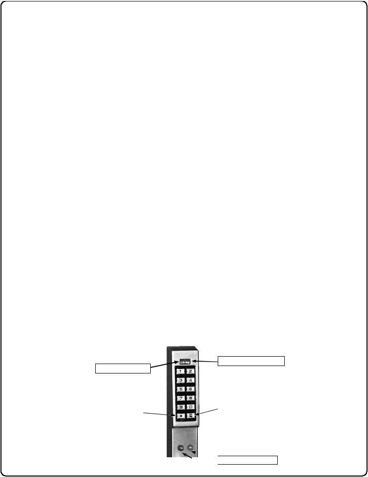
Preparing to Program your Lock
Notice that the keypad contains 12 buttons, numbers 1 through 9 plus zero, a star button (:) and a special "AL" button (;).
These 12 buttons are all you need to program your lock. In addition to manually programming your lock (using only the keypad), you can also program your lock using a computer program named DL-Windows. DL-Windows is not required--but it makes programming faster and easier. This guide will show you how to program your lock manually, without DL-Windows. (For information about programming DL-Windows, see User Guide OI237).
Programming your lock begins after you unpack it from the box -- there is a specific procedure outlined in "Quick Start" (page 12) in which you "wake up" the lock to prepare it for programming. This "Quick Start" procedure shows you all the steps required to get your lock to start working. To begin programming, you must first enter something called "Program Mode".
What is Program Mode?
With hardware, hand tools can be used to make fixes or changes. With software, however, changes are made using the keypad. The software has only two "modes"--"Normal Mode" and "Program Mode". When you want to make changes to the lock program, you enter "Program Mode". When you finish programming and wish to put the lock into use, you exit Program Mode to enter "Normal Mode".
You enter Program Mode using the keypad--by pressing the Master Code of the lock that was set at the factory. The Master Code is basically a secret passcode that allows you to enter Program Mode. But since all locks are identical when leaving the factory (all new locks have the same Master Code), this "factory Master Code" is therefore not very secret--and should be changed to your own personal Master Code. This way, only YOU can enter Program Mode and make changes to the lock programming.
Once your new Master Code is set , then you can continue with the Quick Start procedure and set the weekday, date and time. After this, you can start entering User Codes for people to use. All changes to the lock are organized by their Function Number. Want to change the date? Use Function Number 38. Want to add a User Code? Use Function Number 2. Some Functions you will use often, and others you may never need.
Notice that when you program your lock, programming tends to follow a consistent 5-step pattern: (1) Enter Program Mode
(2) Press ;followed by the Function # (3) Press ;and enter data (4) Press :to end (5) Exit Program Mode.
Turn the page and learn about the special terminology used with your lock. Once that is clear, use the Quick Start procedure on page 12 to help you get up and running.
Infrared LED (for Printer)
Two-Color Status LED
|
|
Special "AL" (;) Key |
|
"STAR" (:) Key |
|||
|
|
 PC / AL-DTM Interface
5

Terminology Used in this Manual
What is a Lock Program?
A Lock Program contains the instructions that a lock uses to perform its various functions. You can use the keypad to create a Lock Program stored within the lock. You can also use DL-Windows (defined below) to create a Lock Program on your computer, and then transfer and store the Program in the circuitry contained inside the lock itself. The Lock Program is essentially a computer database file that maintains feature settings, schedules, audit trails, etc. Using DL-Windows, Lock Programs can be created with default information, edited on your PC, and then sent to (and even received from) locks.
The Lock Program consists of 4 areas: User Codes, Features, Time Zones, and Schedules, all defined below:
What are User Codes?
Also called User Access Codes or PIN Codes, User Codes are numbers the User enters into the lock keypad to unlock the lock. The User Codes are part of the Lock Program, and the Lock Program is stored in the lock circuitry awaiting the Users to key in their User Codes.
What are Features?
Your lock is designed to support several options and functions. Using the keypad or DL-Windows software, you can select the features you wish to activate, such as if the lock will automatically adjust for Daylight Saving Time in the spring and autumn, or if the lock sounder should be disabled or enabled.
What is a TimeZone?
Events (recorded lock activities) can be programmed to occur at certain times. It is these times (for example, “every Tuesday at 5PM”) that are referred to as TimeZones. TimeZones can be created manually through the keypad. You can use DL-Windows to create these TimeZones, and once created, you can link events to these TimeZones.
What is a Schedule?
Your lock can be programmed to maintain a schedule in which certain events can occur automatically. For example, you can program the lock to allow Groups of Users (with their User Codes) access ONLY during specific business hours. With another example, you can program another lock to UNLOCK at 9am, LOCK at noon for lunch, UNLOCK at 1pm, and LOCK again at 5pm--every weekday. As you can see, many different combinations of Schedules can be created to suit the needs of the Users. First you create TimeZones (see above). Next you create events and link them to your TimeZones (also using DL-Windows). When finished, you can view (in DL-Windows) your schedule.
What is a User?
A User is a person who is authorized to simply use or make certain programming changes to the lock. This User can be anyone--from a one-time visitor (who will almost certainly have no authority to make changes) to the owner of the building in which the lock is installed (who will probably wish to have total authority to make changes). The DL1300 Series lock can hold up to 2000 Users in its programming memory, and each User possesses a pre-defined level of authority--a Programming Level--as to their ability to use or make changes to the lock.
What is a Programming Level?
The Programming Level defines the range of programming tasks a User is allowed to perform. The higher the Level, the more programming tasks the User is allowed (with Master allowing ALL tasks).
Note: Since the Programming Level is closely associated with the type of User and their abilities, a User who holds a certain Programming Level is sometimes referred to by their “User Type”.
For example, DL1300 Series locks can hold up to 2000 Users in its programming memory, and each User is associated with a User Number (see definition of "User Number" below) and therefore a specific Programming Level, as follows:
Master: Always associated with User Number 1. Is always enabled and can program all functions. (Abbreviated as Programming Level = M).
Installer: Always associated with User Numbers 2 and 3. Can program all functions except changing the Master Code. (Abbreviated as Programming Level = 4).
Manager: Always associated with User Numbers 4, 5, and 6. Can program all functions except functions relating to lock configuration. (Abbreviated as Programming Level = 3).
Supervisor: Always associated with User Numbers 7, 8 and 9. Can only program functions relating to day to day operation. (Abbreviated as Programming Level = 2).
Print Only Users: Always associated with User Numbers 10 & 11. Restricted to print event logs only. No other programming ability allowed. (Abbreviated as Programming Level = 1).
Basic Users: Always associated with User Number 12 and higher (except 297-300). No programming ability allowed. Most Users are Basic Users, who are given their own personal User Codes and are only allowed to simply unlock the lock when desired.
Programming Levels are hierarchical--higher levels are allowed to do anything the levels below them can do. For example, if you are a Manager, you are allowed to do anything that
Supervisors, Print-Only Users and Basic Users can do in addition to those tasks allowed for Managers (Level 3).
What is the Minimum Required Program Level?
This Programming Level abbreviation is the minimum programming level required to access the particular Function. (The higher the level number, the more programming tasks the User is allowed, with Master allowing all tasks).
In this manual, Programming Levels for the DL1300 are abbreviated as follows: M = Master, 4 = Installer, 3 = Manager, 2 = Supervisor, 1 = Print Only Users
See page 8 for more information, and see page 6 for the location of these "Minimum Required Program Level" numbers.
What is a User Number?
(User Number = Location Number = User Location = Slot in Lock)
User Numbers are used and are significant within each individual lock only. The User Number determines the Programming Level for each User. For example, DL1300 Series locks can hold up to 2000 Users in its programming memory. This mem-
6

Terminology Used in this Manual (cont'd)
ory can be thought of as simply a numbered list from 1 through 2000. Each entry in the list is represented by a User Number. Therefore, where a User is located in this list--their User Location--is a commonly used description of their User Number. Because of their similarities, a User Number, User Location and Location Number can be used interchangeably. In some DL-Windows screens, the word "Slot" is also used. They all mean the same thing.
Since User Numbers are fixed, knowing a User Number will specify the associated Programming Level, and will in turn indicate a User’s programming abilities. For example, User Number 1 is always the Master, who can perform all programming tasks.
Programming Levels are hierarchical--higher levels are allowed to do anything the levels below them can do. For example, if you are User 2, you are allowed to do anything that Users 3 through 2000 can do.
What is a Group?
With many lock applications, it is convenient for large numbers of similar Users to be grouped together. Placing Users into Groups (by assigning them specific User Numbers) allows large numbers of Users to be controlled all at once rather than individually--saving time and effort. Groups can be controlled via schedules, and a typical example involves enabling or disabling a Group at a certain time. Default Group associations are specified in the tables on page 8. For example, if you wish to add a User to Group 1, assign this User a User Number between 51 and 100. These default Group associations can be changed if needed to allow Groups larger than the default number of 50 (by using keypad Function 35). See page 18 for some Group function examples.
Who are Users 297-300?
Users assigned to User Numbers 297, 298, 299 and 300 have special abilities, as follows:
User 297: Quick Enable User 300
User 297 possesses the unique ability to enable the User Code associated with User 300. User 297 does this by first entering their own User 297 User Code into the lock keypad. When User 300 subsequently enters their User 300 User Code, the lock allows access (for one time) and then the User 300 User Code becomes disabled.
For example, you wish to allow one-time access to a temporary worker. Simply enter the User 297 User Code into the lock keypad. Later, when the temporary worker enters the
User 300 User Code into the lock keypad, the User 300 User Code allows access (for one time only) and then becomes disabled. Later, if you wish to grant the temporary
worker re-access, simply re-enter the User 297 User Code and the User 300 User Code will be re-enabled (again for one time only).
User 298: Quick PC Access Code
Entering the User Code for User 298 enables that User to send data to or from the lock. Therefore, User 298 can activate what is the equivalent of Function 58 in Program Mode (see page 22), without the need to enter Program Mode nor the need to know the Master Code of the lock. An AL-PCI cable with a PC is required.
User 299: AL-DTM Code
This is the only User Code that will initiate data transfer with the AL-DTM--and without allowing unlocking the lock (the User Code for User 299 is not an access code). An AL-PCI cable and an AL-DTM (first programmed by the computer in DL-Windows) is required.
User 300: One-Time Only Service Code
This is a One-Time Only Service User Code enabled by User 297. For example, User Code 300 is sometimes used for guard tour duties. See User 297: Quick Enable User 300 above.
What is DL-Windows?
DL-Windows is a computer program that allows you to program your ALARM LOCK security lock. You do not need DLWindows to program your lock, but it makes programming much faster and easier. With DL-Windows, you can quickly create Lock Programs (programs that make the lock perform its many functions) add multiple Users (who have access), retrieve event logs, and create Schedules. The benefit of DLWindows is that it allows you to set up all lock programming in advance (on your computer), and then later send the information to the locks at your convenience.
7
Programming Levels
The Programming Level defines the range of programming tasks a User is allowed to perform. The higher the Level, the more programming tasks the User is allowed (with Master allowing ALL tasks).
Note: Since the Programming Level is closely associated with the type of User and their abilities, a User who holds a certain Programming Level is sometimes referred to by their “User Type”.
For example, DL1300 Series locks can hold up to 2000 Users in its programming memory, and each User is associated with a User Number (see definition of "User Number" in the previous "Terminology" section) and therefore a specific Programming Level, as follows:
Master: Always associated with User number 1. Is always enabled and can program all functions. (Abbreviated as Programming Level = M).
Installer: Always associated with Users 2 and 3. Can program all functions except changing the Master Code. (Abbreviated as Programming Level = 4).
Manager: Always associated with Users 4, 5, and 6. Can program all functions except functions relating to lock configuration. (Abbreviated as Programming Level = 3).
Supervisor: Always associated with Users 7, 8 and 9. Can only program functions relating to day to day operation. (Abbreviated as Programming Level = 2).
Print Only Users: Always associated with Users 10 & 11. Restricted to print audit trails only. No other programming ability allowed. (Abbreviated as Programming Level = 1).
Basic Users: Always associated with User number 12 and higher (except 297-300). No programming ability allowed.
Programming Levels are hierarchical--higher levels are allowed to do anything the levels below them can do. For example, if you are a Manager, you are allowed to do anything that
Supervisors, Print-Only Users and Basic Users can do in addition to those tasks allowed for Managers (Level 3).
Lock Defaults for DL1300
Users added will default to a Group association and a Programming Level as follows:
USER TYPE |
USER NUMBER |
GROUP DEFAULT |
MINIMUM PROGRAM |
|
|
|
|
|
ASSOCIATION |
LEVEL (See page 6) |
|
|
|
|
|
|
|
Master Code |
|
1 |
- |
M |
|
|
|
|
|
|
|
Installer Codes |
2 & 3 |
none |
4 |
|
|
|
|
|
|
|
|
Manager Codes |
4 |
- 6 |
none |
3 |
|
|
|
|
|
|
|
Supervisor Codes |
7 |
- 9 |
none |
2 |
|
|
|
|
|
|
|
Print Only Codes |
10 |
- 11 |
none |
1 |
|
|
|
|
|
|
|
Basic User Codes |
12 |
- 50 |
none |
none |
|
|
|
|
|
|
|
Basic User Codes Group 1 |
51 - 100 |
1 |
none |
|
|
|
|
|
|
|
|
Basic User Codes Group 2 |
101 |
- 150 |
2 |
none |
|
|
|
|
|
|
|
Basic User Codes Group 3 |
151 |
- 200 |
3 |
none |
|
|
|
|
|
|
|
Basic User Codes Group 4 |
201 |
- 250 |
4 |
none |
|
|
|
|
|
|
|
Basic User Codes |
251 |
- 296 |
none |
none |
|
|
|
|
|
|
|
Quick Enable User 300 Code |
297 |
none |
none |
|
|
|
|
|
|
|
|
Quick PC Access Code |
298 |
none |
none |
|
|
|
|
|
|
|
|
AL-DTM Code |
299 |
none |
none |
|
|
|
|
|
|
|
|
Service Code |
300 |
none |
none |
|
|
|
|
|
|
|
|
Basic User Codes |
301-2000 |
none |
none |
|
|
|
|
|
|
|
|
NOTES:
User 299 is a Non-Pass Code. This is the only code that will initiate data transfer with the AL-DTM.
8
Conventions Used in this Manual
Function
Description
Programming
Information
Function
Number
Enabling/Disabling Users (By User Number)
User Number must be between 2 and 2000.
NOTE: Will Enable/Disable users even if the user is associated with an enabled group.
3. |
Disable User |
|
;3 ;[ _ _ _ ] : |
|
|
|
|
|
|
|
|
4. |
Enable User |
|
;4 ;[ _ _ _ ] : |
|
|
|
|
|
|
|
|
Function Name
2
 Minimum Required Program Level
Program Levels are abbreviated as follows:
M = Master
4 = Installer
3 = Manager
2 = Supervisor
1 = Print Only Users
This Program Level abbreviation is the minimum program level required to access the particular Function. (The higher the level, the more programming tasks the User is allowed, with Master allowing all tasks).
Programming Key Sequence.
General Program Mode Information
If a wrong key is pressed during code entry, hold any key continuously until the error sound is heard (7 short beeps), this will clear the entry. Re-enter the key sequence again.
All program sequences are followed by the :key; 2 short beeps indicate a successful program sequence.
LED and Sounder Indicators
The DL1300 Series locks provide visual and audible keypad feedback. With a fully charged battery, the LED and sounder feedback is as follows:
ACTIVITY |
LED |
SOUNDER |
COMMENTS |
Keypress |
1 RED Flash |
1 Beep |
Normal Operation |
|
|
|
|
Access Granted |
3 GREEN Flashes |
3 Beeps |
|
|
|
|
|
Invalid Code |
6 RED Flashes |
6 Beeps |
Re-enter User Code |
|
|
|
|
Successful Program Entry |
2 GREEN Flashes |
2 Beeps |
When in Program Mode |
|
|
|
|
Unsuccessful Program Entry |
7 RED Flashes |
7 Beeps |
When in Program Mode |
|
|
|
|
Exit Program Mode |
2 Red, 2 Green Flashes |
10 Beeps |
|
|
|
|
|
Valid but Disabled Code |
1 Green, 4 Red Flashes |
1 long, 5 short beeps |
Code exists in memory, but disabled |
|
|
|
|
Low Battery |
Red and Green Flash during |
Long Beep |
See page 11 before changing batteries |
|
key presses |
|
|
Non-fatal memory or clock error |
Red and Green Flash |
Sequence of 7 Beeps |
Under this condition, unexpected operation |
has been detected |
|
Repeated 4 Times |
is possible. Remove power and restart. |
9

Product Communication Examples
|
|
|
|
|
|
|
|
Send to lock |
|
|
|
Receive from lock |
|
|
|
|
|
|
|
|
|
|
|
|
|
|
|
|
|
|
|
|
|
|
AL-PCI |
CABLE |
|
|
|
|
|
|
|
|
CONNECT TO |
SERIAL PORT |
|
|
|
|
|
|
|
|
(COM |
1-4) |
|
|
|
|
|
|
|
|
|
|
|
|
|
|
|
|
|
|
|
|
|
|
|
|
|
|
|
NOTE: OBSERVE TAB |
DIRECTION WHEN |
|
|
|
||
|
|
|
|
INSERTING CABLE INTO LOCK |
|
|
|
||
|
|
|
|
|
|
|
|
|
|
|
IBM COMPATABLE |
|
|
|
|
|
|
|
|
|
|
|
|
|
|
|
|
|
|
|
LAPTOP OR DESKTOP PC |
|
|
|
|
|
|
|
|
|
|
|
|
|
|
|
DL1300 LOCK |
|
|
|
|
|
|
|
|
|
|
|
|
|
|
|
|
|
|
|
|
|
|
|
|
|
|
|
|
|
|
|
|
If your computer does not have a serial COM port (DB-9 male) available, you can plug your AL-PCI2 cable into a special USB to RS-232 cable. Order part PCI-USB for the
USB to RS-232 cable only, or ALPCI2-U for both the USB to RS-232 cable and an AL-PCI2 cable).
Scenario 1 Create the program in DL-Windows on your computer, then transfer the program from the computer directly to the lock via an ALPCI2 cable. Enter the User 298 User Code to send or receive data to of from DL-Windows. When no COM port exists, use a USB to RS-232 cable.
AL-PCI CABLE
CONNECT TO SERIAL PORT (COM 1-4)
DOUBLE-ENDED MINI BANANA
PLUG CONNECTOR
NOTE: OBSERVE TAB DIRECTION WHEN
INSERTING CABLE INTO LOCK NOTE: OBSERVE TAB DIREC-
TION WHEN INSERTING CABLE
INTO AL-DTM AND LOCK
IBM COMPATABLE
LAPTOP OR DESKTOP PC
AL-DTM DATA
TRANSFER DL1300 LOCK
MODULE
Scenario 2 Create the program in DL-Windows and transfer the program from your computer to an AL-DTM (via an AL-PCI cable)… then transfer the program from the AL-DTM to the lock(s) (via a double-ended mini banana plug). The hand-held AL-DTM is useful because you do not have to transport (or find electricity for) your computer. Data can also flow in reverse, from the lock, through the AL-DTM, back to the computer for examination.
|
|
AL-IR1 |
DL1300 LOCK |
|
INFRARED PRINTER |
|
|
|
|
|
|
Scenario 4 Use the AL-IR1 Infrared printer to print your lock’s audit trail (event log), User Code list, clock settings and software version. No cable required.
NOTE:
The AL-PCI cable is designed to be used on a 9 pin serial COM port. If your computer has a 25 pin COM port, a 25 pin to 9 pin adapter must be used. Warning: Polarity MUST be observed when connecting cables to the lock. The tab (-) must plug into the negative (black) hole.
10
Wiring and Power Up
WIRING
See the Installation Manual for more information.
Batteries:
Use only 3.0 volt Lithium Type 123 batteries (or equivalent). Two (2) batteries of this type are needed.
BATTERY REPLACEMENT
When a valid code is entered and the batteries are weak, the red & green LED's will light and the sounder will sound for 4 seconds. Replace with two (2) 3.0 volt Lithium Type 123 batteries. Always replace weak batteries as soon as possible.
CAUTION: Do not press any keys while batteries are disconnected or you may erase the real-time clock settings.
1.Insert key in cylinder and turn counterclockwise to allow access to the battery compartment screw. With the supplied 5/64" Allen wrench, loosen the battery cover screw only until the battery cover is able to slide off.
2.Pull out the battery pack and quickly replace both batteries - within 1 minute.
3.If you do not hear the 3 beeps when power is re-applied, all programming and settings have been retained, and the lock is ready for use. Go to step 5.
4.If you do hear 3 beeps when power is re-applied, do not press any keys for 15 seconds. After the 15 second period, the LED will flash red 6 times and 6 beeps will sound. Reset the clock using functions 38, 39 and 40.
5.Slide the battery cover back in place and tighten the screw.
POWER UP
•When applying power to the lock for the first time, stop and follow the procedure outlined in "Quick Start, First Time Start Up" on page 12.
•When power is re-applied to a lock that was already operational, proceed as follows:
1.Disconnect battery pack connector.
2.With battery power disconnected, press and hold down ;for 10 seconds to ensure discharge of all capacitors.
3.Re-connect battery pack (lock will sound 3 short beeps). If beeps are not heard, then restart at step 1.
4.Do not press any keys for 15 seconds.
5.After 15 seconds, the LED will flash red 6 times and 6 beeps will sound.
The lock is now ready for use. The pre-existing program is loaded from fixed memory. Reset the clock using functions 38, 39 and 40 if necessary.
ERASE ALL PROGRAMMING
RESTORE FACTORY DEFAULT (original "out of box" settings that were set at the factory will be loaded).
1. Enter the current Master Code (if not known, proceed
directly to ALTERNATIVE METHOD, below). Wait for the green light and press ;until multiple beeps are
heard. You are now in Program Mode.
2.Press ;99;000:.
3.Listen for 6 beeps. The lock will re-lock. All settings and programming have been erased. Proceed directly to page 12, Quick Start, and follow the procedure "Enter Program Mode and Change Factory Master Code".
ALTERNATIVE METHOD
Note: This method requires the lock first be removed from the door.
1.Insert key in cylinder and turn counterclockwise to allow access to the battery compartment screw. With the supplied 5/64" Allen wrench, loosen the battery cover screw only until the battery cover is able to slide off.
2.Disconnect the battery pack.
3.Remove the back plate by unscrewing the two Phillips head screws. Note: Some models have four Phillips head screws. Be careful not to damage the motor drive wires.
4.Locate jumper header JP1 near the top of the printed circuit board and install the jumper (provided) across pins 1 and 2 of JP1.
5.Press and hold down ;for 10 seconds (to ensure all power is drained from the lock) and release.
6.Connect the batteries and--within 5 seconds--press and hold ;. After hearing 6 additional beeps, release ;. If you do not hear these 6 additional
beeps, you must start over at step 2. Failure to follow this exact procedure can result in erratic lock behavior.
7.Test by pressing the default Master Code of 123456 (a beep will sound and the lock will unlock).
8.Remove the jumper from JP1 pins 1 and 2 and place jumper on 1 pin for storage.
9.Carefully reinstall the back plate STRAIGHT onto the lock body. Be careful not to pinch or damage the motor drive wires. While inserting the back plate, be sure the rear pin of the tailpiece inserts into the spindle hole-- check this alignment after installation by pushing on the spring-loaded tailpiece to verify that it smoothly moves up and down. Replace the two (or four) Phillips head screws to secure the back plate. Note: It may be necessary to tighten the battery screw previously loosened in step 1.
10.Re-mount the lock on the door. With the battery back inside its compartment, slide the battery cover back in place and tighten the screw.
All settings and programming have been erased. Proceed directly to page 12, Quick Start, and follow the procedure "Enter Program Mode and Change Factory Master Code".
11
 Loading...