

Page 1
INSIDE BATTERY KIT
345 Bayview Avenue
Amityville, New York 11701
For Sales and Repairs 1- 800-ALA-LOCK
For Technical Service 1-800-645-9440
© ALARM LOCK 2006 Publicly traded on NASDAQ Symbol: NSSC www.alarmlock.com
INSTALLATION INSTRUCTIONS
WI1516 2/06
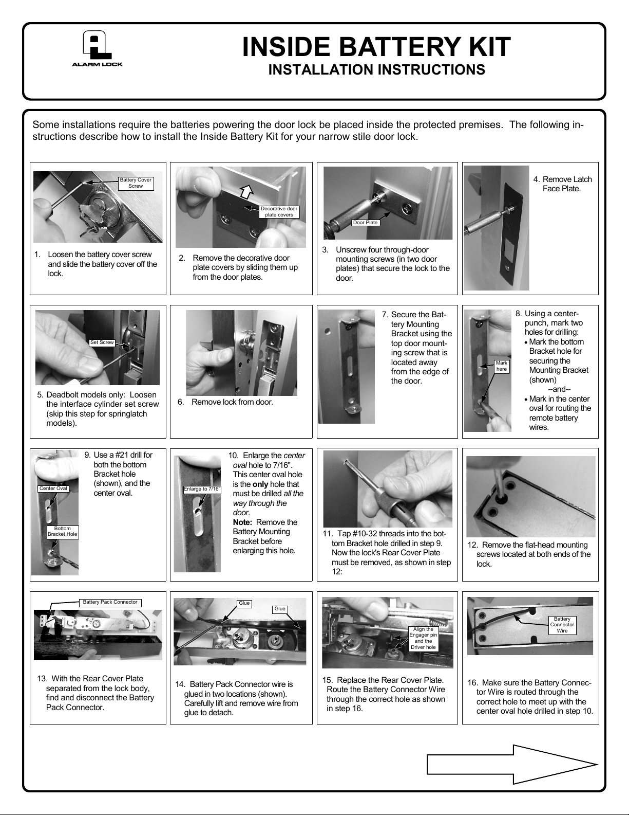
Some installations require the batteries powering the door lock be placed inside the protected premises. The following in-
structions describe how to install the Inside Battery Kit for your narrow stile door lock.
Battery Cover
Screw
1. Loosen the battery cover screw
and slide the battery cover off the
lock.
Set Screw
5. Deadbolt models only: Loosen
the interface cylinder set screw
(skip this step for springlatch
models).
Decorative door
plate covers
2. Remove the decorative door
plate covers by sliding them up
from the door plates.
6. Remove lock from door.
Door Plate
3. Unscrew four through-door
mounting screws (in two door
plates) that secure the lock to the
door.
7. Secure the Bat-
tery Mounting
Bracket using the
top door mount-
ing screw that is
located away
from the edge of
the door.
Mark
here
4. Remove Latch
Face Plate.
8. Using a center-
punch, mark two
holes for drilling:
• Mark the bottom
Bracket hole for
securing the
Mounting Bracket
(shown)
--and--
• Mark in the center
oval for routing the
remote battery
wires.
9. Use a # 21 drill for
both the bottom
Bracket hole
Center Oval
Bottom
Bracket Hole
(shown), and the
center oval.
Battery Pack Connector
13. With the Rear Cover Plate
separated from the lock body,
find and disconnect the Battery
Pack Connector.
10. Enlarge the center
oval hole to 7/16".
This center oval hole
Enlarge to 7/16"
is the only hole that
must be drilled all the
way through the
door.
Note: Remove the
Battery Mounting
Bracket before
enlarging this hole.
Glue
Glue
14. Battery Pack Connector wire is
glued in two locations (shown).
Carefully lift and remove wire from
glue to detach.
11. Tap #10-32 threads into the bot-
tom Bracket hole drilled in step 9.
Now the lock's Rear Cover Plate
must be removed, as shown in step
12:
Align the
Engager pin
and the
Driver hole
15. Replace the Rear Cover Plate.
Route the Battery Connector Wire
through the correct hole as shown
in step 16.
12. Remove the flat-head mounting
screws located at both ends of the
lock.
Battery
Connector
Wire
16. Make sure the Battery Connec-
tor Wire is routed through the
correct hole to meet up with the
center oval hole drilled in step 10.
continued
Page 2
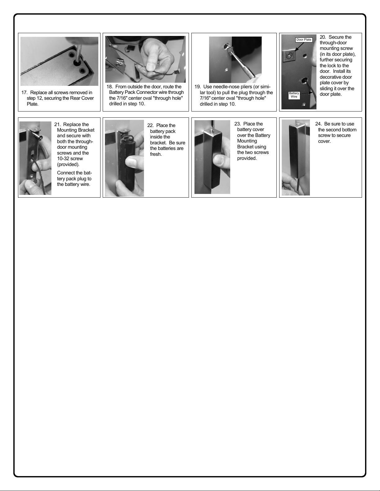
17. Replace all screws removed in
step 12, securing the Rear Cover
Plate.
18. From outside the door, route the
Battery Pack Connector wire through
the 7/16" center oval "through hole"
drilled in step 10.
19. Use needle-nose pliers (or simi-
lar tool) to pull the plug through the
7/16" center oval "through hole"
drilled in step 10.
Battery
Wire
Door Plate
20. Secure the
through-door
mounting screw
(in its door plate),
further securing
the lock to the
door. Install its
decorative door
plate cover by
sliding it over the
door plate.
21. Re place the
Mounting Bracket
and secure with
both the through-
door mounting
screws and the
10-32 screw
(provided).
Connect the bat-
tery pack plug to
the battery wire.
22. Place the
battery pack
inside the
bracket. Be sure
the batteries are
fresh.
23. Place the
battery cover
over the Battery
Mounting
Bracket using
the two screws
provided.
24. Be sure to use
the second bottom
screw to secure
cover.
 Loading...