

Page 1
A-100IMWP
345 Bayview Avenue
Amityville, New York 11701
For Sales and Repairs 1-800-ALA-LOCK
For Technical Service 1-800-645-9440
Publicly traded on NASDAQ Symbol: NSSC
© ALARM LOCK 2006
WIRING & PROGRAMMING INSTRUCTIONS
ILLUMINATED MULLION KEYPAD
GENERAL DESCRIPTION
The A-100IMWP is a self-contained access control keypad
designed outdoor applications. Its heavy stainless steel mul-
lion-style surface mount enclosure is designed to be used in
narrow stile applications. The A-100IMWP operates up to
three outputs (two relays and 1 open-collector transistor)
and can be used to trigger a door strike, an electromagnetic
door lock, or any other relay-activated device. Programming
is performed manually at the keypad, allowing up to 150 indi-
vidual Users, each with their unique User Codes. The A-100
Series includes the indoor stainless steel A-100 (see
WI1495) and the rugged sealed environment A-100WP (see
WI1496).
In a typical application, the A-100IMWP will energize one or
both relays upon the keypad entry of a valid User Code.
Outputs 1 and 2 are two relays of the three contact Form C
type, and Output 3 is an open collector transistor (terminal
labeled "OC") that switches "on" (closes with the ground ter-
minal) when energized. The length of time the outputs are
energized (their "activation duration") can be programmed to
between 1 and 99 seconds. A Request-to-Exit button will
momentarily short Output 1 by wiring terminals M and P1
using a normally-open momentary-close switch.
To program the keypad functions you must first perform the
initial startup procedure, then enter Program Mode by press-
ing the Master Code at the keypad. Once in Program Mode,
all system functions can be accessed and programmed.
Exit Program Mode to put the keypad (with its new program-
ming) into use.
A-100IMWP Wiring Table
Description Wire Colors
+ 12V or 24V AC/DC Input Red
– Ground Black
Request to Exit Input Purple
Request to Exit Input Pink
Relay 1 Normally Open Yellow
Relay 1 Common Brown
Relay 1 Normally Closed Dark Blue
Relay 2 Normally Open Light Blue
Relay 2 Common Light Green
Relay 2 Normally Closed Orange
Open Collector Output Dark Green
Tamper SW Output Gray
Tamper SW Output White
WI1497 7/06
SPECIFICATIONS
• 12 to 24VDC (polarized) or 12 to 24VAC voltage input
• Output 1: 5A/250VAC relay
• Output 2: 1A/125VAC relay
• Output 3: 250mA open collector
• Capacity of 150 User Codes of 3 to 6 digits
• Output activation duration programmable from 01-99
seconds (program "00" to select "toggle" mode)
• All programming stored in non-volatile EEPROM mem-
ory
• Orange LED Keypress feedback
• Output #1 relay activation duration programmable per
user code
• Keypad illumination duration programmable from 10-99
seconds (for backlit keypad models only)
• Tamper switch output terminals (S1 - S2) on PCB
• Sounder feedback "beeps" can be activated or deacti-
vated for user code entries
• Operating Temperature: -13°F to 131°F
-25°C to +55°C
• Dimensions (WxHxD): 1¾" x 6½" x 1 1/8"
4.4cm x 16.5cm x 2.9cm
• Operating Voltage: 12VDC to 28VDC
10VAC to 26 VAC
• Maximum Current Draw:
12VDC: 15mA (Standby) 108mA (Active)
24VDC: 21mA (Standby) 125mA (Active)
12VAC: 33mA (Standby) 192mA (Active)
24VAC: 54mA (Standby) 233mA (Active)
GETTING STARTED
First Time Startup--Self-Test
After you unpack the lock from its factory packaging, we
recommend you perform the initial startup procedure
(outlined below). For keypads already in use, this startup
procedure can also be used to erase all existing keypad
programming and return the keypad back to its original
"out of box" factory default condition.
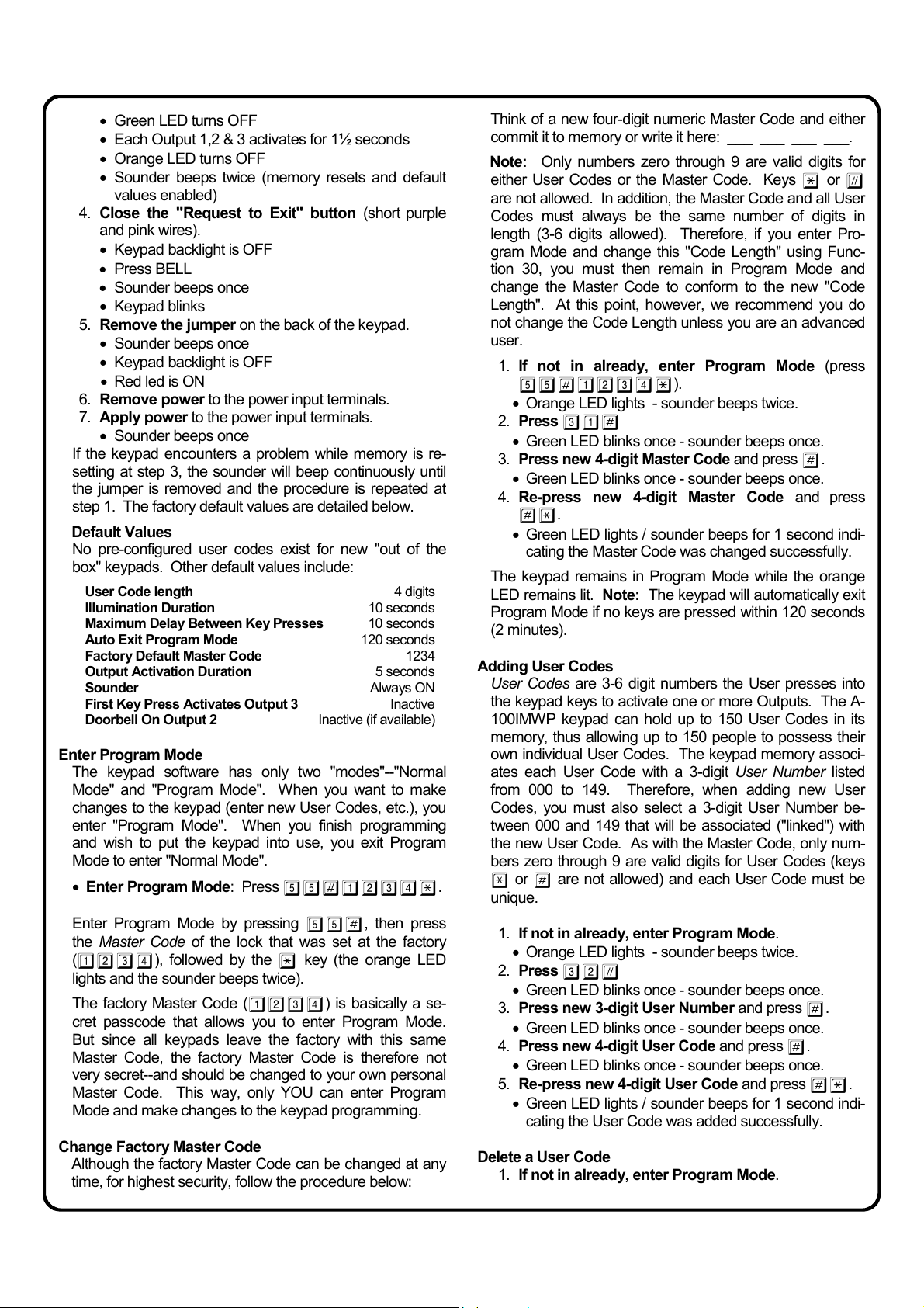
1. Install the jumper located on the back of the keypad
(right position).
2. Apply power (12-24VDC polarized or 12-24VAC) to
the power input terminals.
• Orange LED blinks once
3. Press
7890#123456*
• Red LED turns ON
• Orange LED turns ON
• Green LED turns ON
1
Page 2
• Green LED turns OFF
• Each Output 1,2 & 3 activates for 1½ seconds
• Orange LED turns OFF
• Sounder beeps twice (memory resets and default
values enabled)
4. Close the "Request to Exit" button (short purple
and pink wires).
• Keypad backlight is OFF
• Press BELL
• Sounder beeps once
• Keypad blinks
5. Remove the jumper on the back of the keypad.
• Sounder beeps once
• Keypad backlight is OFF
• Red led is ON
6. Remove power to the power input terminals.
7. Apply power to the power input terminals.
• Sounder beeps once
If the keypad encounters a problem while memory is re-
setting at step 3, the sounder will beep continuously until
the jumper is removed and the procedure is repeated at
step 1. The factory default values are detailed below.
Default Values
No pre-configured user codes exist for new "out of the
box" keypads. Other default values include:
User Code length 4 digits
Illumination Duration 10 seconds
Maximum Delay Between Key Presses 10 seconds
Auto Exit Program Mode 120 seconds
Factory Default Master Code 1234
Output Activation Duration 5 seconds
Sounder Always ON
First Key Press Activates Output 3 Inactive
Doorbell On Output 2 Inactive (if available)
Enter Program Mode
The keypad software has only two "modes"--"Normal
Mode" and "Program Mode". When you want to make
changes to the keypad (enter new User Codes, etc.), you
enter "Program Mode". When you finish programming
and wish to put the keypad into use, you exit Program
Mode to enter "Normal Mode".
• Enter Program Mode: Press 55#1234*.
Enter Program Mode by pressing
55#, then press
the Master Code of the lock that was set at the factory
(
1234), followed by the * key (the orange LED
lights and the sounder beeps twice).
The factory Master Code (1234) is basically a se-
cret passcode that allows you to enter Program Mode.
But since all keypads leave the factory with this same
Master Code, the factory Master Code is therefore not
very secret--and should be changed to your own personal
Master Code. This way, only YOU can enter Program
Mode and make changes to the keypad programming.
Change Factory Master Code
Although the factory Master Code can be changed at any
time, for highest security, follow the procedure below:
Think of a new four-digit numeric Master Code and either
commit it to memory or write it here: ___ ___ ___ ___.
Note: Only numbers zero through 9 are valid digits for
either User Codes or the Master Code. Keys
* or #
are not allowed. In addition, the Master Code and all User
Codes must always be the same number of digits in
length (3-6 digits allowed). Therefore, if you enter Pro-
gram Mode and change this "Code Length" using Func-
tion 30, you must then remain in Program Mode and
change the Master Code to conform to the new "Code
Length". At this point, however, we recommend you do
not change the Code Length unless you are an advanced
user.
1. If not in already, enter Program Mode (press
55#1234*).
• Orange LED lights - sounder beeps twice.
2. Press
31#
• Green LED blinks once - sounder beeps once.
3. Press new 4-digit Master Code and press
#.
• Green LED blinks once - sounder beeps once.
4. Re-press new 4-digit Master Code and press
#*.
• Green LED lights / sounder beeps for 1 second indi-
cating the Master Code was changed successfully.
The keypad remains in Program Mode while the orange
LED remains lit. Note: The keypad will automatically exit
Program Mode if no keys are pressed within 120 seconds
(2 minutes).
Adding User Codes
User Codes are 3-6 digit numbers the User presses into
the keypad keys to activate one or more Outputs. The A-
100IMWP keypad can hold up to 150 User Codes in its
memory, thus allowing up to 150 people to possess their
own individual User Codes. The keypad memory associ-
ates each User Code with a 3-digit User Number listed
from 000 to 149. Therefore, when adding new User
Codes, you must also select a 3-digit User Number be-
tween 000 and 149 that will be associated ("linked") with
the new User Code. As with the Master Code, only num-
bers zero through 9 are valid digits for User Codes (keys
* or # are not allowed) and each User Code must be
unique.
1. If not in already, enter Program Mode.
• Orange LED lights - sounder beeps twice.
2. Press
• Green LED blinks once - sounder beeps once.
3. Press new 3-digit User Number and press
• Green LED blinks once - sounder beeps once.
4. Press new 4-digit User Code and press
• Green LED blinks once - sounder beeps once.
5. Re-press new 4-digit User Code and press
• Green LED lights / sounder beeps for 1 second indi-
Delete a User Code
1. If not in already, enter Program Mode.
32#
#.
#.
#*.
cating the User Code was added successfully.
2
Page 3
• Orange LED lights - sounder beeps twice.
2. Press
34#
• Green LED blinks once - sounder beeps once.
3. Press the 3-digit User Number associated with the
User Code you wish to delete and press
#*.
• Green LED lights / sounder beeps for 1 second indi-
cating the User Code was deleted successfully.
Exit Program Mode
When you finish programming and wish to put the keypad
into use, you exit Program Mode to enter "Normal Mode"
as follows:
• Exit Program Mode: Press *.
The orange LED turns off, the sounder beeps twice and
the red LED lights. Note: The keypad will automatically
exit Program Mode if no keys are pressed within 120 sec-
onds (2 minutes).
Test the Keypad
Be sure to test all User Codes. Keep in mind the follow-
ing:
• Valid User Codes must be followed by the star (
*) key
• Master Code and User Codes must all be the same
length
• By default, a valid User Code always activates Output 1
unless Output selection is changed
ALL PROGRAMMING FUNCTIONS
Your keypad is designed to support several options and
functions. Using the keypad, you can select the features
you wish to activate, such as if the keypad sounder should
be disabled or enabled or you wish to change the code
length from 4 to 6 digits..
Each function is organized below by its function number,
which is the first two digits pressed into the keypad when
programming. To program, first enter Program Mode as
follows:
• Enter Program Mode: Press 55# [Master Code]
*.
When you finish programming and wish to put the key-
pad into use, exit Program Mode to enter "Normal Mode"
as follows:
• Exit Program Mode: Press *.
Note: The audible sounder and visual LED indicators
are displayed in the text below as follows:
[O2] = Orange LED lights and sounder beeps twice
[G1] = Green LED lights and sounder beeps once
[R2] = Red LED lights and sounder beeps twice
Note: Every duration field is a two digit field. Master code
is strictly reserved for entering Program Mode and cannot
be used to activate an Output.
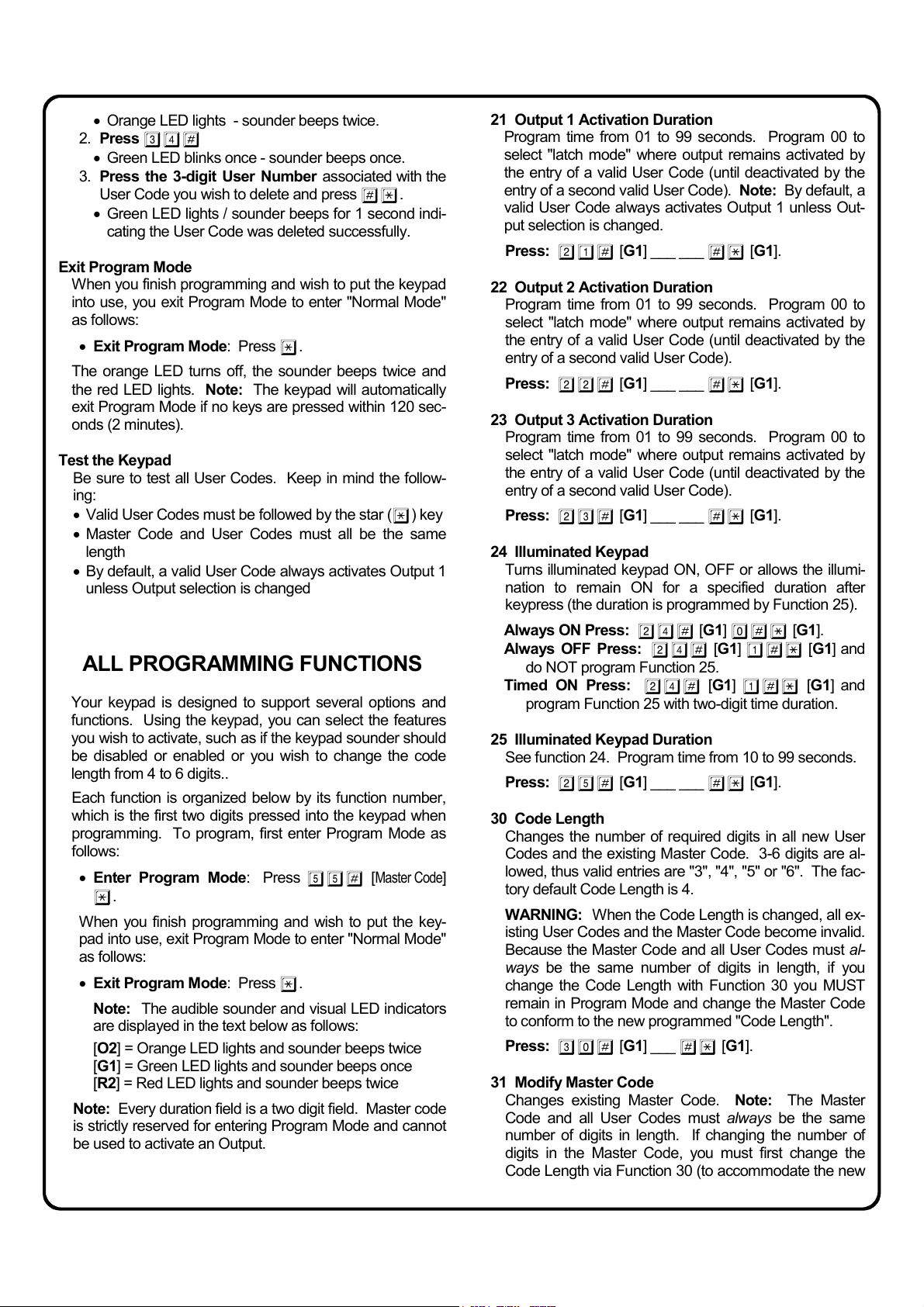
21 Output 1 Activation Duration
Program time from 01 to 99 seconds. Program 00 to
select "latch mode" where output remains activated by
the entry of a valid User Code (until deactivated by the
entry of a second valid User Code). Note: By default, a
valid User Code always activates Output 1 unless Out-
put selection is changed.
Press: 21# [G1] ___ ___ #* [G1].
22 Output 2 Activation Duration
Program time from 01 to 99 seconds. Program 00 to
select "latch mode" where output remains activated by
the entry of a valid User Code (until deactivated by the
entry of a second valid User Code).
Press: 22# [G1] ___ ___ #* [G1].
23 Output 3 Activation Duration
Program time from 01 to 99 seconds. Program 00 to
select "latch mode" where output remains activated by
the entry of a valid User Code (until deactivated by the
entry of a second valid User Code).
Press: 23# [G1] ___ ___ #* [G1].
24 Illuminated Keypad
Turns illuminated keypad ON, OFF or allows the illumi-
nation to remain ON for a specified duration after
keypress (the duration is programmed by Function 25).
Always ON Press: 24# [G1] 0#* [G1].
Always OFF Press:
24# [G1] 1#* [G1] and
do NOT program Function 25.
Timed ON Press:
24# [G1] 1# * [G1] and
program Function 25 with two-digit time duration.
25 Illuminated Keypad Duration
See function 24. Program time from 10 to 99 seconds.
Press: 25# [G1] ___ ___ #* [G1].
30 Code Length
Changes the number of required digits in all new User
Codes and the existing Master Code. 3-6 digits are al-
lowed, thus valid entries are "3", "4", "5" or "6". The fac-
tory default Code Length is 4.
WARNING: When the Code Length is changed, all ex-
isting User Codes and the Master Code become invalid.
Because the Master Code and all User Codes must al-
ways be the same number of digits in length, if you
change the Code Length with Function 30 you MUST
remain in Program Mode and change the Master Code
to conform to the new programmed "Code Length".
Press: 30# [G1] ___ #* [G1].
31 Modify Master Code
Changes existing Master Code. Note: The Master
Code and all User Codes must always be the same
number of digits in length. If changing the number of
digits in the Master Code, you must first change the
Code Length via Function 30 (to accommodate the new
3
Page 4

number of digits in the new Master Code) and--without
exiting Program Mode--change the Master Code via
Function 31.
Press: 31# [G1] (new MC) # [G1] (new MC) #*
[G1].
Be sure to either commit the Master Code to memory or
record it in a safe place. If the Master Code is ever lost,
the keypad will need to be restarted using the First Time
Startup procedure described on page 2.
32 Add (or Edit) a User Code
Allows you to add a new or edit an existing User Code.
User Codes are 3-6 digit numbers the User presses into
the keypad keys to activate one or more Outputs. The
A-100IMWP keypad can hold up to 150 User Codes in
its memory, thus allowing up to 150 people to possess
their own individual User Codes. The keypad memory
associates each User Code with a 3-digit User Number
listed from 000 to 149. Therefore, when adding new
User Codes, you must also select a 3-digit User Number
between 000 and 149 that will be associated ("linked")
with the new User Code. As with the Master Code, only
numbers zero through 9 are valid digits for User Codes
(keys
* or # are not allowed) and each User Code
must be unique. Programming requires entering the
new User Code twice for confirmation, as follows:
Press: 32# [G1] (User Number) # [G1] (User Code)
# [G1] (re-enter User Code) #* [G1].
33 Add (or Edit) a User Code with Output 1 Duration
Same as Function 32 plus the ability of the individual
User Code to activate Output 1 for a specified duration
(from 01 to 99 seconds). Program 00 to select "latch
mode" where output remains activated by the entry of a
valid User Code (until deactivated by the entry of a sec-
ond valid User Code).
Press: 33# [G1] (time 01-99) # [G1] (User Number)
# [G1] (User Code) # [G1] (re-enter User Code)
#* [G1].
34 Delete User Code
Overwrites specified User Number with vacant data,
thus erasing the User Code from memory.
Press: 34# [G1] (User Number) #* [G1].
40 Reset Keypad
Erase all existing keypad programming and return the
keypad back to its original "out of box" factory default
condition
Press: 40# [G1] 12345# [G1]
52 Add (or Edit) a User Code with Output Activation
Same as Function 32 plus the ability of the individual
User Code to activate the specified Output(s).
Press: 52# [G1] (2-digits*) # [G1] (User Number) #
12345#* [G1].
[G1] (User Code)
# [G1] (re-enter User Code)
#* [G1].
*Some examples of the "2-digits" field:
• press "12" to activate Outputs 1 and 2
• press "23" to activate Outputs 2 and 3
• press "13" to activate Outputs 1 and 3
• press "02" to activate Output 2 only
• press "10" to activate Output 1 only ...etc.
Note: If Function 70 ("Output 3 Activates on First
Keypress") is enabled, Output 3 cannot be included in
the choices offered by Function 52.
Note: If “Doorbell Active on Output 2” is enabled, Output
2 cannot be included in the choices offered by Function
52. The value in “Output 2 timer value” (from 01 to 99
seconds) is the duration of relay #2 activation when the
door bell button is momentarily pressed. If the door bell
activation must follow the key press action, then “Output
2 timer value” should be 00.
60 Sounder Beeps
Activate sounder beeping or deactivate when pressing
User Codes only.
Always ON Press: 60# [G1] 1#* [G1].
OFF for User Codes:
Sounder factory default is "Always ON".
70 Output 3 Activates on First Keypress
Enable Output 3 to activate upon any first keypress
when in "Normal Mode" (such as the first keypress when
entering a User Code). Output 3 is a 250mA open col-
lector transistor output. Function 70 can be used for
many purposes, such as to trigger a surveillance camera
to record all activity at the keypad. In addition, Output 3
is silent, therefore Users will be unaware when Output 3
is activated. Function 70 can also be used to deactivate
this feature, as follows:
Activate Press: 70# [G1] 1#* [G1].
Deactivate Press:
Note: If Function 70 is enabled, Output 3 cannot be in-
cluded in the choices offered by Function 52.
80 Doorbell Feature
Program time from 01 to 99 seconds. Program 00 to
select "latch mode" where output remains activated by
the entry of a valid User Code (until deactivated by the
entry of a second valid User Code). Note: By default, a
valid User Code always activates Output 1 unless Out-
put selection is changed.
Activate on Output 2 Press: 80# [G1] 1#* [G1].
Deactivate Press:
Note: If “Doorbell Active on Output 2” is enabled, Output
2 cannot be included in the choices offered by Function
52. The value in “Output 2 timer value” (from 01 to 99
seconds) is the duration of relay #2 activation when the
door bell button is momentarily pressed. If the door bell
activation must follow the key press action, then “Output
2 timer value” should be 00.
60# [G1] 0#* [G1].
70# [G1] 0#* [G1].
80# [G1] 0#* [G1].
4
Page 5

Audible Sounder Indicators
Beep(s) In Normal Mode In Program Mode
1 short Unit power up and when a key is
pressed
1 long Relay activation following a valid
User Code
2 short Enter Program Mode Exit Program Mode
4 short Data error Data Error
Valid data confirmation
Data recorded
Visual LED Indicators
LED In Normal Mode In Program Mode
Red Remains lit while waiting for a
Orange Flashes to confirm keypress Steady On to confirm in Program Mode.
Green Confirms activation of Outputs, mem-
ory reset and Master Code reset
keypress
Blinks when editing an existing User Number
Confirms valid data or empty User Number
Confirms errors
Flashes to confirm keypress
WIRING EXAMPLES
ONE KEYPAD CONTROLS A
DOOR
The diagram at right displays
basic wiring--how to control a
single door with one keypad.
When you enter a valid code on
Keypad 1, the magnetic lock
unlocks directly. This wiring is
"Fail Secure" which means that if
power is lost, the door will remain locked.
A-100IMWP Wiring Table
Description Wire Colors
+ 12V or 24V AC/DC Input Red
– Ground Black
Request to Exit Input Purple
Request to Exit Input Pink
Relay 1 Normally Open Yellow
Relay 1 Common Brown
Relay 1 Normally Closed Dark Blue
Relay 2 Normally Open Light Blue
Relay 2 Common Light Green
Relay 2 Normally Closed Orange
Open Collector Output Dark Green
Tamper SW Output Gray
Tamper SW Output White
12-24 VDC /
VAC Power
Electromagnetic
Door Lock
(Fail Secure)
N/O
Requestto-Exit
Button
TWO KEYPADS CONTROL ONE DOOR
The below diagram displays how to control a single door with two keypads. When you enter a valid code on Keypad
2, the magnetic lock unlocks directly. When you enter a valid code on Keypad 1, the Request-to-Exit input of keypad
2 is triggered, unlocking the door. Note: Valid user codes must be programmed into both Keypads 1 and 2.
A-100IMWP Wiring Table
Light Green
Dark Green
White
Gray
Orange
Light Blue
Dark Blue
Brown
Yellow
Pink
Purple
Black
Red
12-24 VDC /
VAC Power
A-100IMWP Wiring Table
Light Green
Dark Green
White
Gray
Electromagnetic
Door Lock
(Fail Safe)
Orange
Light Blue
Dark Blue
Brown
Yellow
Pink
Purple
Black
Red
12-24 VDC /
VAC Power
5
Page 6

PROGRAMMING FUNCTIONS--OVERVIEW
The audible sounder and visual LED indicators are displayed in the text below as follows:
[O2] = Orange LED lights and sounder beeps twice
[G1] = Green LED lights and sounder beeps once
[R2] = Red LED lights and sounder beeps twice
PROGRAM MODE
FUNCTION
NUMBER
55
DESCRIPTION PRESS THESE BUTTONS ON KEYPAD
Enter Program Mode
Press 55# [Master Code] *
--
Exit Program Mode
USER FUNCTIONS
FUNCTION
NUMBER
30
31
32
33
34
52
DESCRIPTION PRESS THESE BUTTONS ON KEYPAD
Code Length
Modify Master Code
Add (or Edit) a User Code
Add (or Edit) a User Code
with Output 1 Duration
Delete User Code
Add (or Edit) a User Code
with Output Activation
TIMER FUNCTIONS
FUNCTION
NUMBER
21
22
DESCRIPTION PRESS THESE BUTTONS ON KEYPAD
Output 1 Activation Duration
Output 2 Activation Duration
Press *
Press: 30# [G1] ___ #* [G1].
Press: 31# [G1] (new MC) # [G1] (new MC) #* [G1].
Press: 32# [G1] (User Number) # [G1] (User Code) # [G1] (re-enter User
Code)
#* [G1].
Press: 33# [G1] (time 01-99) # [G1] (User Number) # [G1] (User Code) #
[G1] (re-enter User Code)
#* [G1].
Press: 34# [G1] (User Number) #* [G1].
Press: 52# [G1] (2-digits) # [G1] (User Number) # [G1] (User Code) # [G1]
(re-enter User Code)
#* [G1].
Program time from 01 to 99 seconds. Press: 21# [G1] ___ ___ #* [G1].
Program time from 01 to 99 seconds. Press: 22# [G1] ___ ___ #* [G1].
23
25
Output 3 Activation Duration
Illuminated Keypad Duration
SYSTEM FUNCTIONS
6
FUNCTION
NUMBER
24
40
60
70
80
DESCRIPTION PRESS THESE BUTTONS ON KEYPAD
Illuminated Keypad
Reset Keypad
Sounder Beeps
Output 3 Activates on
First Keypress
Doorbell Feature
Program time from 01 to 99 seconds. Press: 23# [G1] ___ ___ #* [G1].
Program time from 10 to 99 seconds. Press: 25# [G1] ___ ___ #* [G1].
Always ON Press: 24# [G1] 0#* [G1].
Always OFF Press:
Timed ON Press:
24# [G1] 1#* [G1] and do NOT program Function 25.
24# [G1] 1#* [G1] (program Function 25 with two-digit time)
Press: 40# [G1] 12345# [G1] 12345#* [G1].
Always ON Press: 60# [G1] 1#* [G1].
OFF for User Codes:
60# [G1] 0# * [G1].
Activate Press: 70# [G1] 1#* [G1].
Deactivate Press:
70# [G1] 0#* [G1].
Activate on Output 2 Press: 80# [G1] 1#* [G1].
Deactivate Press:
80# [G1] 0#* [G1].
Page 7

MOUNTING TEMPLATE
The A-100IMWP is designed to be installed in its stainless mounting base. The base is 1½" wide and 6" tall.
7
Page 8

ALARM LOCK LIMITED WARRANTY
ALARM LOCK SYSTEMS, INC. (ALARM LOCK) warrants its products to be free from manufacturing defects in materials and
workmanship for 24 months following the date of manufacture. ALARM LOCK will, within said period, at its option, repair or
replace any product failing to operate correctly without charge to the original purchaser or user.
This warranty shall not apply to any equipment, or any part thereof, which has been repaired by others, improperly installed,
improperly used, abused, altered, damaged, subjected to acts of God, or on which any serial numbers have been altered,
defaced or removed. Seller will not be responsible for any dismantling or reinstallation charges.
THERE ARE NO WARRANTIES, EXPRESS OR IMPLIED, WHICH EXTEND BEYOND THE DESCRIPTION ON THE FACE
HEREOF. THERE IS NO EXPRESS OR IMPLIED WARRANTY OF MERCHANTABILITY OR A WARRANTY OF FITNESS
FOR A PARTICULAR PURPOSE. ADDITIONALLY, THIS WARRANTY IS IN LIEU OF ALL OTHER OBLIGATIONS OR
LIABILITIES ON THE PART OF ALARM LOCK.
Any action for breach of warranty, including but not limited to any implied warranty of merchantability, must be brought within the
six months following the end of the warranty period. IN NO CASE SHALL ALARM LOCK BE LIABLE TO ANYONE FOR ANY
CONSEQUENTIAL OR INCIDENTAL DAMAGES FOR BREACH OF THIS OR ANY OTHER WARRANTY, EXPRESS OR
IMPLIED, EVEN IF THE LOSS OR DAMAGE IS CAUSED BY THE SELLER'S OWN NEGLIGENCE OR FAULT.
In case of defect, contact the security professional who installed and maintains your security system. In order to exercise the
warranty, the product must be returned by the security professional, shipping costs prepaid and insured to ALARM LOCK. After
repair or replacement, ALARM LOCK assumes the cost of returning products under warranty. ALARM LOCK shall have no
obligation under this warranty, or otherwise, if the product has been repaired by others, improperly installed, improperly used,
abused, altered, damaged, subjected to accident, nuisance, flood, fire or acts of God, or on which any serial numbers have
been altered, defaced or removed. ALARM LOCK will not be responsible for any dismantling, reassembly or reinstallation
charges.
This warranty contains the entire warranty. It is the sole warranty and any prior agreements or representations, whether oral or
written, are either merged herein or are expressly canceled. ALARM LOCK neither assumes, nor authorizes any other person
purporting to act on its behalf to modify, to change, or to assume for it, any other warranty or liability concerning its products.
In no event shall ALARM LOCK be liable for an amount in excess of ALARM LOCK's original selling price of the product, for any
loss or damage, whether direct, indirect, incidental, consequential, or otherwise arising out of any failure of the product. Seller's
warranty, as hereinabove set forth, shall not be enlarged, diminished or affected by and no obligation or liability shall arise or
grow out of Seller's rendering of technical advice or service in connection with Buyer's order of the goods furnished hereunder.
ALARM LOCK RECOMMENDS THAT THE ENTIRE SYSTEM BE COMPLETELY TESTED WEEKLY.
Warning: Despite frequent testing, and due to, but not limited to, any or all of the following; criminal tampering, electrical or
communications disruption, it is possible for the system to fail to perform as expected. ALARM LOCK does not represent that
the product/system may not be compromised or circumvented; or that the product or system will prevent any personal injury or
property loss by burglary, robbery, fire or otherwise; nor that the product or system will in all cases provide adequate warning or
protection. A properly installed and maintained alarm may only reduce risk of burglary, robbery, fire or otherwise but it is not
insurance or a guarantee that these events will not occur. CONSEQUENTLY, SELLER SHALL HAVE NO LIABILITY FOR ANY
PERSONAL INJURY, PROPERTY DAMAGE, OR OTHER LOSS BASED ON A CLAIM THE PRODUCT FAILED TO GIVE
WARNING. Therefore, the installer should in turn advise the consumer to take any and all precautions for his or her safety
including, but not limited to, fleeing the premises and allege police or fire department, in order to mitigate the possibilities of
harm and/or damage.
ALARM LOCK is not an insurer of either the property or safety of the user's family or employees, and limits its liability for any
loss or damage including incidental or consequential damages to ALARM LOCK's original selling price of the product regardless
of the cause of such loss or damage.
Some states do not allow limitations on how long an implied warranty lasts or do not allow the exclusion or limitation of
incidental or consequential damages, or differentiate in their treatment of limitations of liability for ordinary or gross negligence,
so the above limitations or exclusions may not apply to you. This Warranty gives you specific legal rights and you may also
have other rights which vary from state to state.
NOTE: This equipment has been tested and found to comply with the limits for a Class B digital device, pursuant to part
15 of the FCC Rules. These limits are designed to provide reasonable protection against harmful interference in a residential installation. This equipment generates, uses and can radiate radio frequency energy and, if not installed and used
in accordance with the instructions, may cause harmful interference to radio communications. However, there is no guarantee that interference will not occur in a particular installation. If this equipment does cause harmful interference to radio
or television reception, which can be determined by turning the equipment off and on, the user is encouraged to try to correct the interference by one or more of the following measures: —Reorient or relocate the receiving antenna. —Increase
the separation between the equipment and receiver. —Connect the equipment into an outlet on a circuit different from
that to which the receiver is connected. —Consult the dealer or an experienced radio/ TV technician for help.
8
 Loading...