

Page 1
INSTALLATION INSTRUCTIONS
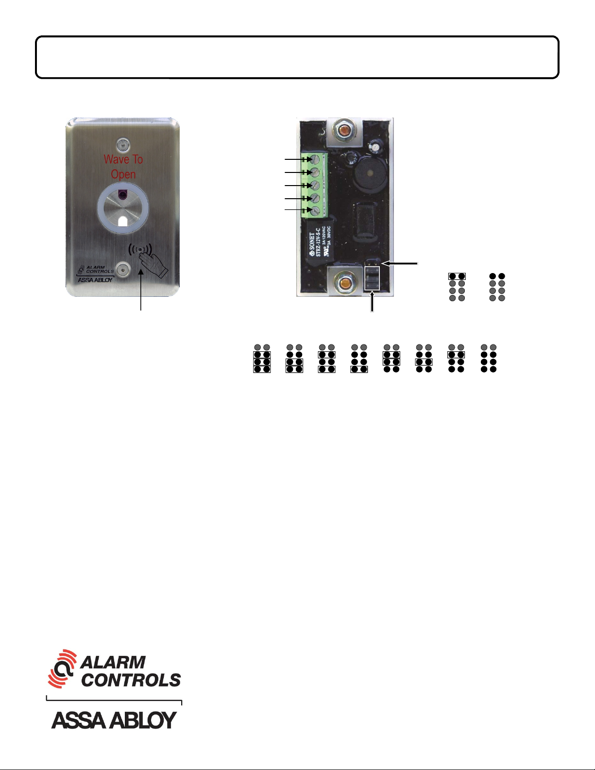
MODEL NTS-1
To ensure proper wire connection note that the silver contact
Power +
Power -
N/C
C
N/O
of the terminal block is all the
way down when loosened.
Proper connection is made
when tightening the screw on
the terminal block such that the
silver contact rises upward to
clamp the wire in place.
LED Selection Jumper
Backup Button
(Use if motion detection fails to operate switch)
Red
Time Delay
LED
Selection Jumpers
1 Sec 5 Sec 10 Sec 15 Sec 20 Sec 25 Sec 30 Sec 35 Sec
Green
LED
Specifications -
Input Voltage: 12-24 Volts DC
SPDT Contact Rating: 2A @ 30 Volts AC or DC
Sensor Detection Range: Up to approximately 4 inches
Operating Temperature: -25°C to +55°C
Current Draw: 50mA @12VDC, 65mA @ 24VDC
Operation -
To operate the switch, make a slow waving motion with your hand within approximately 4 inches of the front
of the plate. A tone will sound indicating that the relay has been activated. Switch relay will activate for the
amount of time as set by the time delay jumpers.
The LED circle on the front of the plate can be set to either the color red (flashes green in 1 second intervals
when relay is active) or green (flashes red in 1 second intervals when relay is active).
The Backup Button can be used if the motion detector fails to activate the relay.
Alarm Controls
19 Brandywine Drive
Deer Park, New York 11729
(800) 645-5538
www.alarmcontrols.com
NTS-1 Instructions Rev. A 4/14
 Loading...