


|
|
|
|
|
|
|
|
|
|
|
|
|
|
|
|
|
|
GM526 |
Ax/i/sp/fl1616a_A4 |
||||
Edition 07.97 |
|||||
Supersedes AX/i/sp/fl 1616
ªCopyright -- Details as per general conditions of supply, 1997
|
Operating radius |
|
Coverage area |
|
Wirkradius |
|
Wirkbereich |
r = |
Rayon d’action |
F = |
Domaine d’efficacité |
Raggio d’azione |
Campo d’azione |
||
F |
Radio de acción |
|
Campo de actuación |
Aanspreekstraal |
|
Aanspreekgebied |
|
1 |
|
|
|
Small safe made in single steel layer (‡6...12mm thickness)
Kleiner Tresor in einfacher Stahlausführung (‡6...12mm Materialstärke) Petit coffre-fort en version acier simple épaisseur (épaisseur ‡6...12mm) Piccola cassaforte in lamiera di acciaio semplice (spessore ‡6...12mm) Caja de seguridad pequeña de chapa de acero simple (grosor ‡6...12mm) Kluisje gemaakt van enkele staalplaat (‡6...12mm materiaaldikte)
0.4m · 0.4m · 0.4m = 0.065m3
|
|
|
1 detector |
1 rivelatore |
|
|
|
||
|
|
|
1 Melder |
1 detector |
|
|
|
1 détecteur |
1 detektor |
|
|
|
Solid metal cases (‡2...6mm thickness) |
|
|
Solide Stahlschränke (‡2...6mm Materialstärke) |
||
Armoires en acier massif (épaisseur ‡2...6mm) |
||
Casse di metallo solido (spessore ‡2...6mm) |
|
|
Cofre de metal macizo (grosor ‡2...6mm) |
|
|
Solide stale kasten (‡2...6mm materiaaldikte) |
|
|
0.75m · 0.75m · 0.75m = 0.42m3 |
or any other size £0.5m3 |
|
|
oder eine beliebige andere Grösse £0,5m3 |
|
|
ou toute autre dimension £0,5m3 |
|
|
o altre dimensioni £0,5m3 |
|
|
o cualquier oltra dimensión £0,5m3 |
|
1.5m |
of een willekeurig ander lichaam £0,5m3 |
|
|
|
|
1.5m |
|
|
|
1 detector |
1 rivelatore |
|
1 Melder |
1 detector |
|
1 détecteur |
1 detektor |
1.0m · 1.0m · 1.0m = 1.0m3
1.5m |
1.5m |
|
1.0m |
2
or any other size £1.0m3
oder eine beliebige andere Grösse £1,0m3 ou toute autre dimension £1,0m3
o altre dimensioni £1,0m3
o cualquier oltra dimensión £1,0m3
of een willekeurig ander lichaam £1,0m3
2 detectors |
2 rivelatori |
2 Melder |
2 detectores |
2 détecteurs |
2 detektoren |
3 |
|
|
µ 60mm |
4 |
|
|
min. 6 |
|
ø3,2 |
|
M4 |
5 |
6 |
7 |
8 |
9 |
10 |
DIP switches |
|
|
Interrutori DIP |
|
|
|
||||
DIP-Schalter |
|
|
Conmutadores DIP |
|
|
|||||
Interrupteurs DIP |
|
DIP-schakelaars |
|
|
|
|||||
SW1 -- SW5 |
|
|
|
|
|
|
|
|
|
|
|
|
|
|
|
|
|
|
|
|
|
Shock |
SW1 |
SW2 |
|
Response |
SW3 |
|
|
Sensi- |
SW4 |
SW5 |
|
|
|
|
time |
|
|
|
tivity |
|
|
high |
ON |
ON |
|
standard |
ON |
|
|
high |
ON |
ON |
|
|
|
|
|
|
|
|
|
|
|
|
OFF |
ON |
|
delayed |
OFF |
|
|
|
OFF |
ON |
|
|
|
|
|
|
|
|
|
|
|
|
ON |
OFF |
|
|
|
|
|
|
ON |
OFF |
low |
|
|
|
|
|
|
|
low |
|
|
OFF |
OFF |
|
|
|
|
|
OFF |
OFF |
||
|
|
|
|
|
|
|
|
|
|
|
11
Downloaded from: - http://www.guardianalarms.net
SW1 -- SW5
|
|
|
|
|
|
|
|
|
|
|
|
|
|
|
|
|
|
|
|
|
|
|
|
|
|
|
|
|
|
|
|
|
ON |
|
|
|
|
|
|
|
|
|
|
Cover switch |
|||
|
|
|
|
|
|
|
|
|
|
|
|
|
|||
|
|
|
|
||||||||||||
|
|
|
|
|
|
|
|
|
|
|
|
|
Deckelkontakt |
||
|
OFF |
|
|
|
|
|
|
|
|
|
Contact de couvercle |
||||
|
|
|
|
|
|
|
|
|
|
|
|
|
Contatto del coperchio |
||
|
|
|
|
|
|
|
|
|
|
|
|
|
Interruptor de la tapa |
||
|
|
|
|
|
|
|
|
|
|
|
|
|
Sabotage kontakt |
||
|
|
|
|
|
|
|
|
|
|
|
|
|
|
|
|
|
|
|
|
|
|
|
|
|
|
|
|
|
|
|
|
|
|
|
|
|
|
|
|
|
|
|
|
|
|
|
|
|
|
|
|
|
|
|
|
|
|
|
|
|
|
|
|
|
|
|
|
|
|
|
|
|
|
|
|
|
|
|
|
|
|
|
|
|
|
|
|
|
|
|
|
|
|
|
|
|
|
|
|
|
|
|
|
|
|
|
|
|
|
|
|
12
|
|
+5V |
|
IC |
|
|
|
|
|
|
0V |
|
180k |
|
|
|
|
|
* |
|
|
|
|
|
|
|
|
<1.5k |
|
|
||
|
|
9.4k |
|
9.4k |
|
|
|
20R |
||
1 |
2 |
3 |
4 |
9 |
10 |
11 12 14 15 |
||||
0V |
7DC...16V |
REMOTE |
SPARE |
TEST PT |
COVER SWITCH |
EL.ALARM OUTPUT |
ALARM |
RELAY |
COM |
|
|
|
|
|
|
|
|
|
AL.O |
|
|
*Relay shown in energised (non-alarm) condition
Relais in aufgezogenem Zustand (kein Alarm) gezeichnet Le relais est dessinée à l’état attiré (pas d’alarme)
Il relè è rappresentato in stato eccitato (nessun allarme) 13 El relé ha sido dibujado en estado excitado (sin alarma)
Relais in opgetrokken toestand (geen alarm) getekend
Option GMXC2
 µ 5mm
µ 5mm
14

Seismic detector GM526
Installation
Application
The seismic detector GM526 provides reliable protection against attack with explosives and any known tools to open solid metal cases.
Operation
Cutting steel gives rise to mass acceleration. This creates mechanical oscillations which are transmitted as structure-borne sound. The sensor of the seismic detector, which is connected to the object to be monitored, picks up these oscillations and converts them into electrical signals. The detector electronics analyses the signals in a selected frequency range typical for break-in tools, and triggers an alarm via a relay contact.
Adjustable detection sensitivity and selectable response time allow the GM525 to be used for all known monitoring applications, such as
--ticket machines,
--consumer automates,
--phone automates,
--small hotel room safes (£0.065m3) with single layer steel case (for all other larger safes use GM530 or GM560).
Coverage area fig. 1 + 2
The coverage area is designated as the surface of a mechanical obstacle which is monitored by a detector. The coverage area is highly dependent on the material of the object to be monitored. Practical experience has shown that the operating radius for steel is «r» = 1.5m (fig. 1). Note: Joints between two materials always damp the structure-borne noise transmission, therfore not recommended on standard multilayer safes.
Opening the detector fig. 3
The GM526 detector is provided with a double housing. This complicated two-chamber encapsulation provides the detector with extremely good shielding from electromagnetic interference and from accidental or intentional damage.
1.Unscrew the loss-proof front screw and lift off the metal cover. The seismic sensor is now exposed.
2.Use the two pre-assembled M4x8mm Philips head screws provided in order to fix the detector.
Direct mounting on steel fig. 4 to 6
The detector can be installed directly on steel plates with a smooth surface. Ensure that any residual paint between the steel surface and the seismic sensor is completely removed and the mounting surface is plan. If this is not possible, use mounting plate GMXP.
1.Remove residual paint from sensor installation site (fig. 4).
2.Stick on drilling template and centerpunch drill holes (fig. 5).
3.Drill only the two marked holes of 3.2mm dia. and tap M4 thread at least 6mm deep. Deburr threaded holes (fig. 6).
4.Mount detector. Do not use silicon grease between sensor and object!
Indirect installation with mounting plate GMXP fig. 7 to 10
In the case of uneven or hardened steel plates, weld on mounting plate GMXP.
1.Remove residual paint from the welding area (fig. 7).
2.Weld mounting plate in four fixing points. Ensure correct positioning (fig. 9).
The welding symbol must be visible on the front of the mounting plate (fig. 8).
3.Weld along surfaces indicated. Tap off slag and remove weld spatter from the plate surface (fig. 10).
4.Mount detector.
Programming fig. 11 + 12
SW = DIP switches for the following settings.
After the detector housing has been opened, use the DIP switches to select the respective settings.
|
|
Mode |
|
|
|
|
|
|
|
|
|
|
|
|
ON |
|
|
|
|
OFF |
|
||
|
|
|
|
|
|
|
|
|
|
|
|
SW1 |
Shock |
|
see ”Shock settings” |
||||||||
SW2 |
|
||||||||||
|
|
|
|
|
|
|
|
|
|||
SW3 |
|
Response time |
standard |
delayed |
|||||||
SW4 |
Sensitivity |
see ”Settings recommended” |
|||||||||
SW5 |
|
||||||||||
|
|
|
|
|
|
|
|
|
|||
SW1 and SW2 Shock settings
Individual setting for normal or exposed applications.
Shock settings for |
|
normal applications |
high |
light, exposed applications |
|
exposed applications |
|
heavy, exposed applications |
low |
|
SW1 |
SW2 |
|||||||
|
|
|
|
|
|
|
|
|
|
|
|
|
|
|
|
|
|
|
|
|
ON |
|
|
ON |
|
||||
|
|
|
|
|
|
|
|
||
|
|
|
|
|
|
|
|
|
|
|
|
OFF |
|
|
ON |
|
|||
|
|
|
|
|
|
|
|||
|
|
|
|
|
|
|
|
|
|
|
ON |
|
|
|
|
OFF |
|||
|
|
|
|
|
|
|
|
||
|
|
OFF |
|
|
|
OFF |
|||
|
|
|
|
|
|
|
|
|
|
SW3 Response time fig. 11
Standard: Normal response time for standard applications.
Delayed: Double response time to delay any interference produced by automatic cash dispensing mechanisms or heavy functional noise.
SW4 and SW5 Sensitivity setting fig. 11
Select the sensitivity setting to suit the application, the material and the object with the associated interference.
Important: The detection radius will decrease as sensitivity is reduced. Important: During commissioning, be sure to check for function-related noise (see ”Commissioning”).
Settings recommended for SW3, SW4 and SW5
|
|
Response |
|
|
|
Sensitivity |
|
|
|
|
|
||||||||
Objects with |
|
time |
|
|
|
|
|
|
|
|
|||||||||
|
|
|
|
|
|
|
|
|
|
|
|
|
|
||||||
|
SW3 |
|
|
|
|
SW4 |
|
SW5 |
|||||||||||
|
|
|
|
|
|
|
|
||||||||||||
minimum interference |
|
|
|
|
|
|
|
|
|
A |
|
|
|
|
|
|
|
|
|
|
|
ON |
|
|
high |
ON |
|
ON |
|
||||||||||
light interference |
|
|
|
|
|
|
|
B |
|
|
|
|
|
|
|
|
|
||
|
|
|
|
|
|
|
|
|
|
|
|
|
|
|
|||||
|
ON |
|
|
|
|
|
|
OFF |
|
ON |
|
||||||||
function-related noise |
|
|
|
|
|
|
|
|
|
|
|
|
|
|
|
|
|
|
|
|
|
|
|
|
|
|
C |
|
|
|
|
|
|
||||||
|
|
OFF |
|
|
|
|
ON |
|
|
|
OFF |
||||||||
heavy function-related noise |
|
|
|
|
|
low |
D |
|
|
|
|
|
|
|
|
|
|||
|
|
|
|
|
|
|
|
|
|
|
|||||||||
|
|
OFF |
|
|
OFF |
|
|
OFF |
|||||||||||
|
|
|
|
|
|
|
|
|
|
|
|
|
|
|
|
|
|
|
|
Remote controlled sensitivity reduction fig. 13
An additional feature of this detector is a sensitivity reduction input at terminal 3 (Remote) which can be activated from distance if required. Using a LOW signal, the detector is reduced to about 1/5 of the sensitivity setting for as long as there is heavy functional noise (coins!) by means of a contact during cash dispensing.
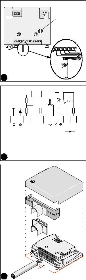
GMXC2 Conduit connection sleeve fig. 14
The function of the GMXC2 conduit connection sleeve is to ensure fixed and secure connection of surface-mounted conduits of an outside diameter of up to 16mm. Smaller-size surface-mounted conduits may require fitting of an appropriate transition sleeve of a maximum outside diameter of 16mm.
To fit the GMXC2 conduit connection sleeve, proceed as follows:
1.Route the surface-mounted conduit to within about 5mm of the detector housing and fit the conduit connection sleeve onto the surfacemounted conduit.
2.Wire the connecting cable and secure in place at the detector by a cable strap (fig. 12).
3.Knock out the entire cable entry in the plastic section.
4.Fit the detector housing onto the conduit connection and detector, tighten the housing screw.
Commissioning
1.Switch on voltage -- wait 1 minute -- the detector is ready for operation.
2.Functional check: Simulate a burglary signal in the supervised area, for example scratch lightly with a screwdriver or testsignal -- the detector should trigger an alarm.
3.Interference checks: Connect an universal measuring instrument (impedance ‡20kW ) between terminal 1 (0V) and output terminal 9 (Test
PT) for integrator signal: |
<0.1V |
-- quiescent level |
|
-- integration start |
2.5V |
-- max. interference level |
3.4V |
-- alarm threshold (without load) |
4.0V |
Normal interference must not exceed the interference threshold of 3.4V. If this value is repeatedly exceeded, localize the source of the interference and eliminate it; reduce the sensitivity only in exceptional cases.
Maintenance
Test detectors regularly (at least once a year) for operation and firm mounting.
Approvals
Any national approval requirements relating to the application of the product must be complied with.
Technical data |
|
|
|
|
Supply voltage (nom. 12V) |
|
7.0...16.0VDC |
||
Current consumption (12VDC/quiescent) |
|
typ. 3.5mA |
||
-- alarm condition |
|
|
5mA |
|
Alarm output |
|
relay, opens at alarm |
||
-- contact |
|
|
30VDC / 100mA |
|
Electronic alarm output (short-circuit proof £16V) |
alarm |
0V |
||
-- alarm hold time |
|
|
2.5s |
|
Tamper surveillance |
|
microswitch, |
||
-- contact rating |
closed with cover in place |
|||
|
30VDC / 100mA |
|||
-- supply voltage |
|
6V...<7V |
alarm |
|
Test point terminal 9 |
analog integrator signal |
|||
-- quiescent level |
|
|
<0.1V |
|
-- integration start |
|
|
2.5V |
|
-- max. interference level |
|
|
3.4V |
|
-- alarm threshold (without load) |
|
|
4.0V |
|
Operating radius |
|
|
1.5m |
|
Coverage area |
|
|
7m2 |
|
Coverage volume |
|
|
0.5m3 |
|
Sensitivity, adjustable in |
|
4 levels |
||
Response time, adjustable in |
|
2 levels |
||
Shock settings |
|
4 levels |
||
Ambient conditions: |
|
--20 ...+60 C |
||
-- operating temperature |
|
|||
-- storage temperature |
|
--50 ...+70 C |
||
-- humidity, DIN class F |
|
|
<95% |
|
-- housing protection category IEC |
|
|
IP43 |
|
-- insensitive to RD interferences |
|
£15V/m |
||
(0.1MHz...1GHz) (IEC801-3) |
|
|||
-- immunity to spike voltages on supply line |
|
|
1kV |
|
-- differential (IEC801-5) |
|
|
||
-- common mode (IEC801-5) |
|
|
3kV |
|
Elements supplied with detector |
|
|
|
|
1 Seismic detector |
|
|
|
|
1 Mounting instructions |
|
|
|
|
1 Mounting template |
|
|
|
|
3 Cable straps |
|
|
|
|
GM526 |
Seismic detector |
|
503 536 |
|
GMXP |
Mounting plate |
|
276 737 |
|
GMXC2 |
Conduit connection sleeve 16mm |
|
502 184 |
|

Körperschallmelder GM526
Montage
Einsatz
Der Körperschallmelder GM526 dient zuverlässig zum Schutz gegen Angriffe mit Sprengstoff und sonstige Versuche, einen stabilen Metallbehälter mit irgendeinem derzeit bekannten Werkzeug zu öffnen.
Funktionsweise
Beim Bearbeiten von harten Materialien, wie Beton, Stahl oder Kunststoffbewehrungen, entsteht eine Massenbeschleunigung. Dadurch werden mechanische Schwingungen erzeugt, die als Körperschall übertragen werden. Der Sensor des Körperschallmelders, der mit dem zu überwachenden Objekt verbunden ist, nimmt diese Schwingungen auf und wandelt sie in elektrische Signale um. Die Melderelektronik analysiert die Signale in einem ausgewählten Frequenzbereich, der für Einbruchwerkzeuge charakteristisch ist, und löst über einen Relaiskontakt Alarm aus.
Da die Detektionsempfindlichkeit und die Ansprechzeit sich einstellen lassen, kann der GM525 für alle denkbaren Überwachungsaufgaben eingesetzt werden, wie zum Beispiel bei
--Fahrscheinautomaten,
--Verkaufsautomaten,
--Fernsprechautomaten,
--kleinen Hotelzimmer-Tresoren (£0,065m3) in einfacher Stahlausführung (für alle grösseren Tresore GM530 oder GM560 verwenden).
Wirkbereich Abb. 1 und 2
Als Wirkbereich wird die Oberfläche eines von einem Melder überwachten Gegenstandes bezeichnet. Der Wirkbereich ist in hohem Masse vom Material des zu überwachenden Objektes abhängig. Nach der Erfahrung in der Praxis gilt für Stahl ein Wirkradius «r» von 1,5m (Abb. 1). Achtung: Fugen zwischen zwei Materialien dämpfen in jedem Fall die Übertragung des Körperschalls, daher für Multilayer-Safes nicht geeignet.
Öffnen des Melders Abb. 3
Der Körperschallmelder GM526 hat ein Doppelgehäuse. Diese aufwendige Zweikammerkapselung bietet dem Melder ausserordentlich guten Schutz gegen elektromagnetische Beeinflussung sowie unbeabsichtigte oder mutwillige Beschädigung.
1.Die unverlierbare vordere Schraube lösen und den Metalldeckel abheben. Der Körperschallsensor liegt nun frei.
2.Zum Befestigen des Melders die beiden vormontierten Kreuzschlitzschrauben M4x8mm verwenden.
Direktmontage auf Stahl Abb. 4 -- 6
Der Melder kann unmittelbar auf Stahlplatten mit glatter Oberfläche montiert werden. Stellen Sie sicher, dass sich zwischen der Stahloberfläche und dem Körperschallsensor keine Farbreste befinden und die Montagefläche eben ist. Wenn das nicht gewährleistet ist, muss eine Befestigungsplatte GMXP verwendet werden.
1.Von der Montagestelle für den Sensor alle Farbreste entfernen (Abb. 4).
2.Die Montageschablone aufkleben und die Bohrstellen ankörnen (Abb. 5).
3.Bohren Sie nur die beiden markierten Löcher mit einem Durchmesser von 3,2mm, schneiden Sie das M4-Gewinde mindestens 6mm tief. Die Gewindelöcher entgraten (Abb. 6).
4.Montieren Sie den Melder. Zwischen dem Sensor und dem Objekt darf kein Silikonfett aufgetragen werden!
Indirekte Montage mit Befestigungsplatte GMXP Abb. 7 -- 10
Bei Unebenheiten oder Platten aus gehärtetem Stahl ist eine Befestigungsplatte GMXP anzuschweissen.
1.Von der Schweissstelle die gesamte Farbe entfernen (Abb. 7).
2.Die Befestigungsplatte an vier Punkten anheften. Achten Sie auf die richtige Positionierung (Abb. 9).
Das Schweisssymbol muss auf der Vorderseite der Befestigungsplatte zu sehen sein (Abb. 8).
3.Die Schweissnähte entlang der angegebenen Stellen anbringen. Die Schlacke abklopfen und Schweissspritzer von der Plattenoberfläche entfernen (Abb. 10).
4.Montieren Sie den Melder.
Programmierung Abb. 11 und 12
SW = DIP-Schalter für die folgenden Einstellungen.
Nach dem Öffnen des Meldergehäuses sind mit den DIP-Schaltern die entsprechenden Einstellungen vorzunehmen.
|
|
Betriebsarten |
|
|
|
|
|
|
|
|
|
|
|
|
|
ON |
|
|
|
|
|
OFF |
|
||
|
|
|
|
|
|
|
|
|||||
SW1 |
Erschütterung |
|
|
|
|
siehe |
||||||
SW2 |
”Erschütterungs Einstellungen” |
|||||||||||
|
||||||||||||
SW3 |
|
Ansprechzeit |
standard |
|
verzögert |
|||||||
SW4 |
Empfindlichkeit |
siehe ”Empfohlene Einstellungen” |
||||||||||
SW5 |
|
|||||||||||
|
|
|
|
|
|
|
|
|
|
|||
SW1 und SW2: Erschütterungs-Einstellungen
Einstellungen für normale Einsätze und solche mit grösserem Erschütterungspotential:
Erschütterungs-Einstellungen für |
|
|
|
|
SW1 |
SW2 |
|||||||
|
|
|
|
|
|
|
|
|
|
|
|
|
|
normale Anwendungen |
hoch |
|
|
|
|
|
|
|
|
|
|
||
|
ON |
|
|
ON |
|
||||||||
etwas stärkere Erschütterungen |
|
|
|
|
|
|
|
|
|
|
|
|
|
|
|
|
|
|
|
|
|
|
|
|
|
|
|
|
|
|
|
|
OFF |
|
|
ON |
|
||||
stärkere Erschütterungen |
|
|
|
|
|
|
|
|
|
|
|||
|
|
|
|
ON |
|
|
|
|
OFF |
||||
sehr starke Erschütterungen |
niedrig |
|
|
|
|
|
|
|
|
|
|
||
|
|
|
|
|
|
|
|
||||||
|
|
OFF |
|
|
|
OFF |
|||||||
|
|
|
|
|
|
|
|
|
|
|
|
|
|
Einstellungen für normale Einsätze und solche mit grösserem Erschütterungspotential:
SW3: Ansprechzeit Abb. 11
Normal: Normale Ansprechzeit für normale Einsätze.
Verzögert: Verdoppelte Ansprechzeit zum Verzögern von Störeinflüssen, die durch automatische Geldausgabemechanismen oder starke funktionsbedingte Geräusche hervorgerufen werden.
SW4 und SW5: Empfindlichkeitseinstellung Abb. 11
Die Empfindlichkeitseinstellung ist entsprechend dem Einsatz, dem Material und dem Objekt mit den jeweiligen Störeinflüssen zu wählen. Achtung: Der Detektionsradius verkleinert sich mit der Verringerung der Empfindlichkeit.
Achtung: Bei der Inbetriebnahme ist eine Überprüfung auf funktionsbedingte Geräusche durchzuführen (siehe “Inbetriebnahme”).
Empfohlene Einstellungen für SW3, SW4, SW5
|
|
Ansprech- |
|
|
Empfindlichkeit |
|
|
|
|
|||||||||
Objekte mit |
|
|
zeit |
|
|
|
|
|
|
|
|
|
|
|
|
|||
|
SW3 |
|
|
|
|
SW4 |
SW5 |
|||||||||||
|
|
|
|
|
|
|
||||||||||||
|
|
|
|
|
|
|
|
|
|
|
|
|
|
|
|
|
|
|
geringen Störeinflüssen |
|
|
|
|
|
|
hoch A |
|
|
|
|
|
|
|
|
|||
|
|
ON |
|
|
ON |
|
ON |
|
||||||||||
|
|
|
|
|
|
|
|
|
|
|
|
|
|
|
|
|||
leichten Störeinflüssen |
|
|
|
|
|
|
|
|
B |
|
|
|
|
|
|
|||
|
ON |
|
|
|
OFF |
ON |
|
|||||||||||
funktionsbedingten Geräuschen |
|
|
|
|
|
|
|
|
|
|
|
|
|
|
|
|
|
|
|
|
|
|
|
|
|
C |
|
|
|
|
|
||||||
|
|
OFF |
|
|
|
|
ON |
|
|
OFF |
||||||||
starken funktionsbedingten Geräuschen |
|
|
|
|
|
niedrig D |
|
|
|
|
|
|
|
|
||||
|
|
|
|
|
|
|
|
|
|
|||||||||
|
|
OFF |
|
|
OFF |
|
OFF |
|||||||||||
|
|
|
|
|
|
|
|
|
|
|
|
|
|
|
|
|
|
|
Ferngesteuerte Empfindlichkeitsverringerung Abb. 13
Ein weiteres Merkmal dieses Melders ist ein Eingang zur Empfindlichkeitsverringerung (Klemme 3). Bei Bedarf wird mittels eines LOW-Si- gnals die Empfindlichkeit auf etwa 1/5 des eingestellten Wertes reduziert, z. B. für die Dauer starker funktionsbedingter Geräusche (Münzen!) durch einen Kontakt bei der Geldausgabe.
Rohranschlussmuffe GMXC2 Abb. 14
Die Rohranschlussmuffe GMXC2 dient dazu, einen festen und gesicherten Anschluss von Aufputzrohren mit einem Aussendurchmesser von bis zu 16mm herzustellen. Bei kleineren Aufputzrohren ist unter Umständen der Einsatz einer entsprechenden Übergangsmuffe mit einem maximalen Aussendurchmesser von 16mm erforderlich.
Die Rohranschlussmuffe wird folgendermassen eingebaut:
1.Das Aufputzrohr wird bis etwa 5mm vor das Meldergehäuse geführt und die Rohranschlussmuffe auf das Aufputzrohr aufgesetzt.
2.Das Anschlusskabel wird verdrahtet und mit einem Kabelbinder am Melder fixiert (Abb. 12).
3.Der gesamte Kabeleinführungsteil im Kunststoff-Anschlussstück herausbrechen.
4.Das Meldergehäuse auf den Rohranschluss und den Melder aufsetzen, und die Gehäuseschraube festziehen.
 Loading...