

Page 1
INTERSTATER
Assembly Instruction
Manual
New Holland (Cab or Rops Tractor)
TS-100A, TS-1 15A, TS-125A & TS-135A
INTERSTATER
Tractors equipped with additional options, special equipment, tractor manufacturer modifications,
new tractor models, or Customer alterations may prevent this Mount Kit from being properly
mounted to the tractor. Alamo Group is not responsible for modifications to the MountKit to
accommodate these differences.
ALAMO INDUSTRIAL
1502 E. Walnut
Seguin, Texas 78155
210-379-1480
© 2004 Alamo Group Inc.
Manual
P/N 02981188
Page 2

TO THE OWNER/OPERATOR/DEALER
All implements with moving parts are potentially hazardous. There is no substitute for a cautious,
safe-minded operator who recognizes the potential hazards and follows reasonable safety
practices. The manufacturer has designed this implement to be used with all its safety equipment
properly attached to minimize the chance of accidents.
BEFORE YOU START!! Read the safety messages on the implement and shown in your
manual. Observe the rules of safety and common sense!
WARRANTY INFORMATION:
Read and understand the complete Warranty Statement found in this Manual. Fill out the Warranty
Registration Form in full and return it within 30 Days. Make certain the Serial Number of the Machine
is recorded on the Warranty Card and on the Warranty Form that you retain. The use of "will-fit"
parts will void your warranty and can cause catastrophic failure with possible injury or death.
Page 3

INTRODUCTION
ABOUT THIS MANUAL:
The intent of this publication to provide the competent technician with the information necessary
to perform the CORRECT Assembly to the Alamo Industrial Product. This will, in turn provide for
complete customer satisfaction
It is hoped that the information contained in this and other Manuals will provide enough detail to
eliminate the need for contact of the Alamo Industrial Technical Service Dept. However, it should be
understood that many instances may arrive where correspondence with the Manufacturer is necessary.
CONTACTING MANUFACTURER: (Please help us Help You! Before You Call! )
Alamo Industrial Service Staff Members are dedicated to helping you solve your problem, or
your customer’s service problem as quickly and efficiently as possible. Unfortunately, we receive
entirely to many calls with only a minimum amount of information. In some cases, the correspondent
has never gone out to look at the equipment and merely calls inquiring of the problems described to him
by the operator or customer.
Most calls received by Alamo Industrial Service can be classified into approx. 6 general categories.
1. Hydraulic or Mechanical Trouble Shooting.
2. Request for Technical Information or Specifications.
3. Mounting or Fitting Problem.
4. Special Service Problem.
5. Equipment Application Problems.
6. Tractor Problem Inquiries.
HOW YOU CAN HELP:
Make sure the call is necessary! Most of the calls received may not be necessary if the Dealer
Service Technician would do the following.
1. Check the Service Information at your Dealership provided by Alamo Industrial, This
would include, Service Bulletins, Information Bulletins, Parts Manuals, Operators Manuals, Assembly
Manual or Service Manual, many of these are available via the Alamo Industrial Internet site (www.AlamoIndustrial.Com). Attempt to diagnose or repair problem before calling.
2. If a call to Alamo Industrial is needed, Certain Information should be available and ready
for the Alamo Industrial Service Staff. Such information as, Machine Model, Serial Number, Your Dealer
Name, Your Account Number and Any other information that will be useful. This information is vital for
the development of a prompt and correct solution to the problem. This will also help to develop a
database of problems and related solutions, which will expedite a solution to future problems of a similar
nature.
3. The technician may be asked to provide detailed information about the problem
including the results of any required trouble shooting techniques. If the information is not available, The
technician may be asked to get the information and call back. Most recommendations for repairs will
be based on the procedures listed in the Service Manual / Trouble Shooting Guide and Information
provided by customer.
CONTACT ALAMO INDUSTRIAL:
Alamo Industrial, 1502 E. Walnut St. Seguin TX. 78155, Technical Service Dept. PH: 830-379-1480
Interstater (NH TS-100A , 115A , 125A & 135A Asy. Manual) 06/04
© 2004 Alamo Group Inc.
Page 0 - 1
Page 4

INDEX - ASSEMBLY INSTRUCTION
Index
Introduction..................................................................................... Index 1
General Index................................................................................. Index 2 & 3
User / Assmbly Notes..................................................................... Index 4
Section 1
Pre-Dilivery Check List...................................................................... 1-1 to 1-4
Section 2
Mainframe Assembly......................................................................... 2-1 to 2-5
Prepare Tractor................................................................................. 2-2
Prepare Main frame........................................................................... 2-2
Mount Frame Mounting Rails............................................................ 2-2
Removed Parts From Tractor.......................................................... 2-2
Install Mainframe............................................................................... 2-3 to 2-4
Prepare & Mount Valve Assembly.................................................... 2-5
Page
Section 3
Pump - Driveshaft - Hyd. Tank.......................................................... 3-1 to 3-9
Pump & Driveshaft Schematic..........................................................3-2
Prepare Tractor................................................................................. 3-3
Install Driveshaft & Pumps................................................................ 3-3 to 3-4
Connect Fittings & Hoses To Pumps...............................................3-4 to 3-6
Connect Hoses to Frame.................................................................. 3-7 to 3-9
Connect Hoses to Tank & Valve...................................................... 3-8 to 3-9
Install Return Pressure Gauge......................................................... 3-8
Install Oil Level Sight Glass in Tank.................................................. 3-8
Install Oil Temperature Gauge...........................................................3-8
Install Motor & Valve Tank Return Lines............................................3-8
Section 4
Remote Control Cable Connections..................................................4-1 to 4-11
Cylinder to Valve Hose Connections................................................. 4-1 to 4-11
Remote Control Handles Installation (Cab Tractor Only)..................4-4 to 4-5
Remote Control Handles Installation (ROPS Tractor Only)..............4-6
Remote Handle Assembly to Cables ................................................4-7 to 4-9
Hydraulic Hose Routeing, Valve to Cylinders.................................... 4-9
Wire Harness Connections............................................................... 4-10 to 4-11
Interstater (NH TS-100A , 115A , 125A & 135A Asy. Manual) 06/04
© 2004 Alamo Group Inc.
Page 0 - 2
Page 5

INDEX - ASSEMBLY INSTRUCTION
Section 5
Modify tractor Exhaust system.......................................................... 5-1 to 5-3
Section 6
Tractor Fuel Tank Replacement........................................................6-1 to 6-2
Section 7
Wing Mower Installation.....................................................................7-1 to 7-11
Wing Mower Cut Off Switches.......................................................... 7-1 to 7-5
Wing Mower Hose Connections....................................................... 7-6 to 7-11
Wiring Schematic.............................................................................. 7-7
Pump & Motor Hydraulic Schematic................................................. 7-8 to 7-11
Page
Section 8
Rear Mower Installation..................................................................... 8-1 to 8-5
Initial Start-Up Procedure...................................................................8-4 to 8-7
Lubrication chart................................................................................ 8-5
Hydraulic Tank Filling Procedure.......................................................8-6
Section 9
Tractor & Mower Mounting Requirements.........................................9-1 to 9-5
Interstater (NH TS-100A , 115A , 125A & 135A Asy. Manual) 06/04
© 2004 Alamo Group Inc.
Page 0 - 3
Page 6

NOTES
Interstater (NH TS-100A , 115A , 125A & 135A Asy. Manual) 06/04
© 2004 Alamo Group Inc.
Page 0 - 4
Page 7

Section 1
INTERSTATER
New Holland
TS100A, TS115A
TS125A, TS135A
PRE-DELIVER Y INSPECTION
Interstater (NH TS-100A , 115A , 125A & 135A Asy. Manual) 06/04
© 2004 Alamo Group Inc.
Page 1 - 1
Tractor
CHECKLIST
Page 8

PRE-DEL INSPECTION CHECKLIST
Pre-Operation Inspection: Check the following items before operating the unit to
assure that they are properly assembled. (See following page 1-4 for component location)
Saftey Equipment:
___ Operators Manual is with Unit.
___ The Safety Decals are installed as listed in the Assembly Manual.
___ Valve operation plate is installed.
___ Operators cage or Tractor Cab is in place
___ Deflectors are installed on the Mower Head
___ Tractor Rops or Cab with seatbels installed properly.
___ All Foot Guards and safety switch are installed and functional.
Frame:
___ Axle Plate Bolts are torqued.
___ Head Mounting Bolts tightened.
___ Frame attaching Bolts tightened.
___ Front Support Bolts are torqued.
___ Hydraulic Tank mounting Pins / Bolts in place correctly.
___ All Welds inspected toinsure proper welds and locations.
Hydraulic System:
___ Oil Level in Hydraulic Tank is within the sight gauge. (Item 5 page 1-4)
___ Hose connections are tight.
___ Hoses do not have any kinks or twist in them.
___ Front Pump Shaft adapter bolts are tight.
___ Front Pump Shaft Coupler / Drive Shaft is lubricated and has an anti-seize compound
on the Splines of Pump and Shafts.
___ The Pump Drive Shaft has correct alignment.
___ Suction Hose has no leaks or kinks.
Flail Mower Head:
___ Skid Shoe Bolts are torqued to 120 ft-lbs
___ Motor Bolts are torqued to 120 ft-lbs
___ Belt Alignment& tension adjustment is correct.
___ Cutter shaft bearings are properly lubricated
___ Roller bearings are properly lubricated
___ Blades swing freely.
___ All Pins and Clips for Rear Mower are installed
___ Clutch on Rear Mower has been checked for proper adjustment and conditions per
parts book reguirments.
___ All Belt guards are installed correctly.
Interstater (NH TS-100A , 115A , 125A & 135A Asy. Manual) 06/04
© 2004 Alamo Group Inc.
Page 1 - 2
Page 9

PRE-DEL INSPECTION CHECKLIST
Pre-Operation Inspection: Check the following items before operating the unit to assure
that they are properly assembled. (See following page 1-4 for component location)
Tractor Mower Operation Inspection:
Using all Safety precautions, operate the Tractor and Mower unit for 30 minutes and
while the unit is running check the following items: Note! Only make adjustments after
the mower has been turned off and all motion has stopped and all hydraulic pressure
has been relieved.
___ Check for Hydraulic oil leaks at the hose connections
___ Operate the boom and mower head throughout its full range of motion and check
for hose's rubbing, pinching, or kinking.
___ Make sure the Return Filter Gauge is reading in the Green after Oil is warm.
___ Check the function of the Mower Head On-Off Valve and switch for proper function
___ Make sure that the tractor will not start with the mower on-off switch in the on
position.
___ Check the Blade Rotation for the Rotary Mower Head to make sure it is turning
Clockwise looking from the top of the mower deck.
___ Make sure the control valve boom movements agree with the valve operation decal.
___ Make Sure Boom Movement operates as expected and is smooth and under control
(no air in the control system)
___ Look for any unusual or excessive noise or vibrations.
___ Make sure the left rear wheel of the tractor stays on the ground when the boom is
fully extended horizontally with 200 lbs. placed on the outside of the mower head.
Post-Operation Inspection:
___ Check that the oil in the hydraulic tank has not turned milky in color or has foam on top.
___ Check that there are no loose fasteners or hardware.
Interstater (NH TS-100A , 115A , 125A & 135A Asy. Manual) 06/04
Interstater (NH TS-100A , 115A , 125A & 135A Asy. Manual) 06/04
© 2004 Alamo Group Inc.
Page 1 - 3
Page 10
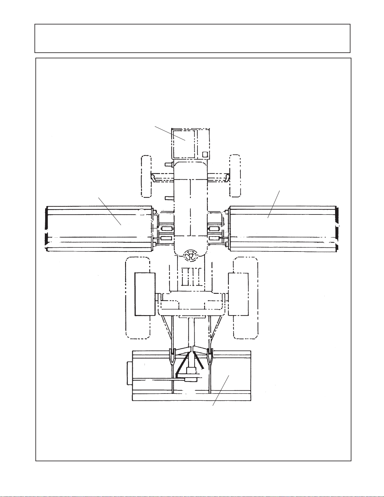
T ractor - Mower Component Location
Check List
Pumps, Hyd.
Tank & Cover
Left Wing
Flail
Right Wing
Flail
Rear Center
Flail
Interstater (NH TS-100A , 115A , 125A & 135A Asy. Manual) 06/04
© 2004 Alamo Group Inc.
Page 1 - 4
Page 11

Section 2
INTERSTATER
New Holland
TS100A, TS115A
TS125A, TS135A
Main Frame Asy.
Interstater (NH TS-100A , 115A , 125A & 135A Asy. Manual) 06/04
© 2004 Alamo Group Inc.
Page 2 - 1
Tractor
Page 12
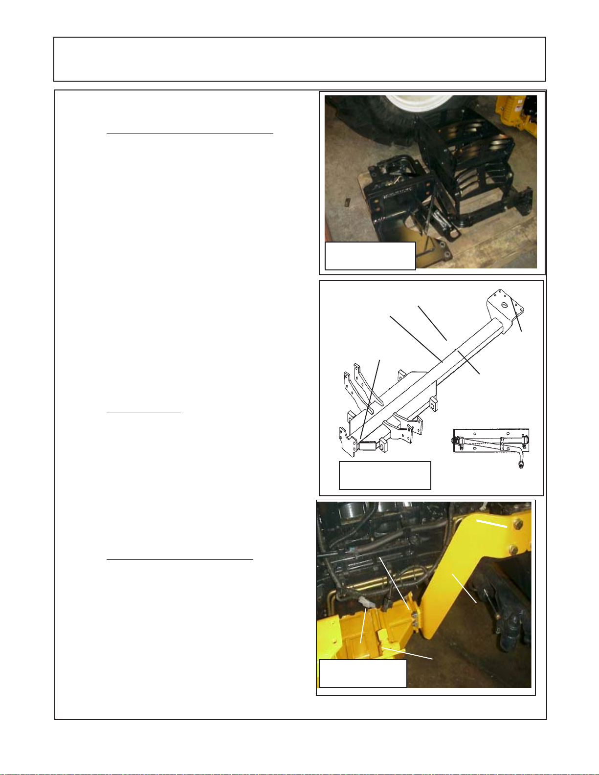
Main Frame Dual / Single Wing
Prepare Tractor:
Remove Components from Tractor. There
are items that must be removed from tractor that
will not be used before the mainframe can be
mounted. On each side of the tractor there heavy
mounting lugs that are bolted to the tractor frame.
One on the left hand and one on the right hand side.
The steps on the left and right side has to be
removed. (See Figure 1) The Battery Relocation Kit
will have to be installed, with this modification the
battery will no longer swing completely out. To
remove Battery after modification is done will best
be done by two people as battery is heavy and will
have to be lifted out. Before beginning any work on
Tractor the Negative Ground Batterycable needs to
be disconnected from the battery to protect the
electrical system. Before reconnecting Battery cable
check all connections that you have made and
make certain all components of the tractor are in the
OFF position.
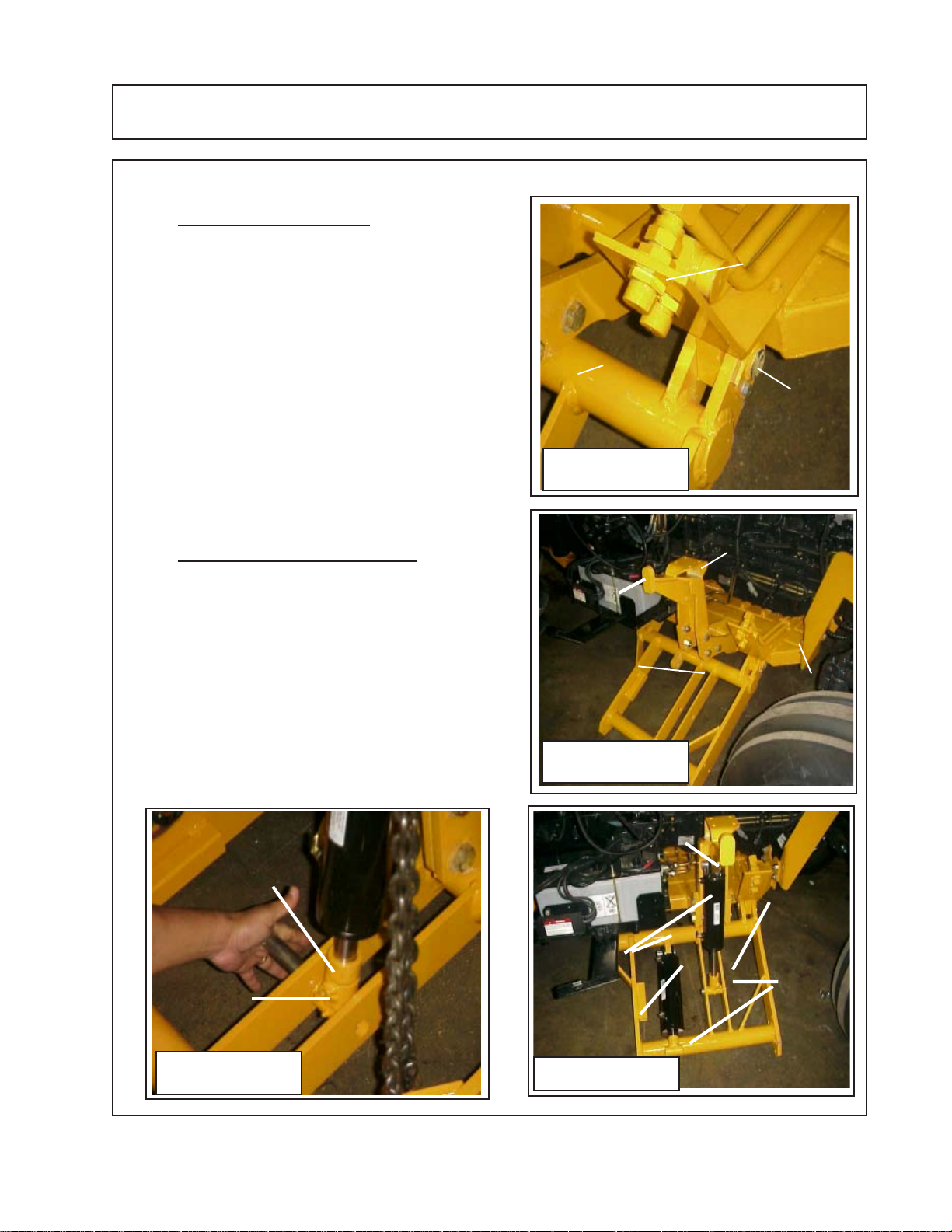
Prepare Main Frame:
The Main frame (See Figure 2) will be bolted
up under the tractor at the rear of the tractor and to
the frame support rails at front. The Hydraulic Tube
bracket & tube assembly needs to be bolted to the
Main frame. Hydraulic Tube Assembly has a left
and a right hand side, the LH and RH side has to be
installed as shown (See Figure 2 & 3). If this is not
bolted on correctly the hoses will not fit correctly
later.
Mount Frame Rails To Tractor:
1. Install the Frame Mounts Rails. There is a
LH and a RH Frame Mounting rail. These will bolt to
the front of the tractor with three mounting bolts on
each side. When Starting the three mounting bolts
it will work best to install the RH Side (See Figure 2)
and the LH Side (See Figure 3). Do not tighten the
three mount bolts on each side , this will allow you
to align mounting bolts easier. Move to the rear of
the tractor under the rear axle, check the threaded
bolt holes in the rear end housing. Remove any
plugs or bolts that will be in the way. (See Figure 4
& 5)
Removed Tractor
Parts that will not be
used
Figure 1
RH Side of
Dual Wing
Mainframe
Shown
Mount to Front
of Tractor
Figure 2
Frame mounting
Mainframe to
frame rail mount-
ing bolts
Mainframe
Figure 3
Tractor
Mount to
Rear of
Tractor
LH Side of
Tractor
RH Side LH Side
Hyd. Tube Asy,
Bolt to Mainframe
rails bolt to
tractor
Frame Mount-
ing Rails RH
Side
Hyd Tube Asy.
Bolted on
Interstater (NH TS-100A , 115A , 125A & 135A Asy. Manual) 06/04
© 2004 Alamo Group Inc.
Page 2 - 2
Page 13
Main Frame Dual / Single Wing
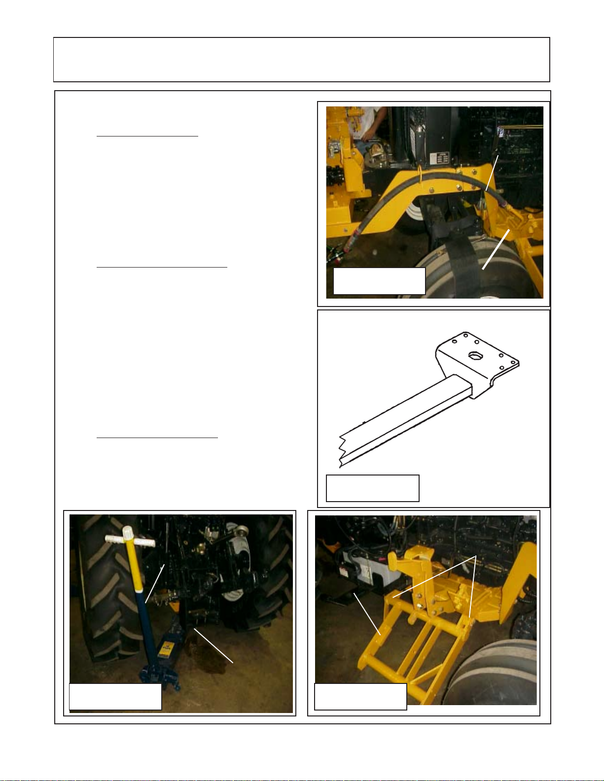
Mount Frame Rails To Tractor:
2. Install the Main Frame. The Mainframe bolts up
under the Tractor from the bottom. Bolt the Hyd Tube
Assembly to the mainframe before sliding it up under
the tractor (See Figure 2 & 3), make certain that the
hyd tube assembly is bolted in the right direction as
shown in Figure 2 as the tubes must be installed
correctly for the hydraulic lines to be installed correctly
later. Use floor jacks to support the mainframe under
tractor (See Figure 6)
3. Tightening Mainframe Bolts. With all the bolts
installed, the bolts at the front of the mainframe to the
frame mounting rails, the bolts through the rear of the
mainframe into the tractor. Tighten the bolts beginning
with the bolts that mount the frame rail mount to the
tractor in the front (See Figure 3 & 4). Second tighten
the four bolts that mount the frame rail to the frame rail
mounts (See Figure 3) . Next tighten the rear mainframe bolts that connects the rear of the mainframe to
the tractor rear axle housing. Once all the bolts are
tightened you can remove any floor jacks from under
main frame.
Figure 4
Bolt to center of
rear tractor axle
using the six
holes in frame
and the threaded
holes in tractor
axle.
Frame Mount-
ing Rails LH
Side
Mainframe
4. Install RH Wing Lift frame. The wing lift frame
pivots on two hinge pins. When installing these pins
they must be aligned in a way that will allow the
retaining bolt to be installed. The Right side and the Left
side will install in the same way (See Figure 7 & 8)
Floor Jack Supporting
Mainframe
Mainframe
Figure 6
under
tractor
Figure 5
Frame Hinge
Pins
RH
Side
Shown
Figure 7
Interstater (NH TS-100A , 115A , 125A & 135A Asy. Manual) 06/04
© 2004 Alamo Group Inc.
Page 2 - 3
Page 14
Main Frame Dual / Single Wing
Mount Frame Rails To Tractor:
5. Install LH Wing Lift frame. The wing lift frame
pivots on two hinge pins. When installing these pins
they must be aligned in a way that will allow the
retaining bolt to be installed. The Right side and the Left
side will install in the same way (See Figure 7 & 8)
6. Install Lift Cylinder Mount Weldment . The lift
cylinder mount is a bolt on weldment that bolts to the
main frame with four bolts. The Left Hand and the right
hand are not the same. The right hand side will have a
mount welded to it to mount the control valve to (See
Figure 8), the left hand mount will not have this plate
welded to it. The LH & RH will bolt on the same way.
Tighten the mounting bolts. Note the bracket also have
the transport lugs welded to them.
7. Install the Lift and Tilt Cylinders. Install the Lift
cylinder and the Tilt Cylinder. When installing these
they must be installed with the rod end clevis grease
fitting facing up and out (See Figure 10 & 11). The
Cylinder for the Left Wing will install the same as the RH
side. The Wing RH & LH Lift Cylinders MUST have
lift control spacers installed to control wing lift
height (See Figure 10 & 11). Do not remove any
shipping plugs from cylinders or hoses until you are
ready to install the hoses, this will keep the system and
components clean while unit is being assembled.
RH Side
Front
Shown
Wing Lift
frame
Hyd Tube
Assembly
Hinge
Pin
Figure 8
RH Wing Lift Cylinder Mounting
Weldment with valve mounting plate
welded to it
Transport
lug
Wing Lift
Frame
Mainframe
Figure 9
Lift Control
Spacer must be
installed on Lift
Cylinders
Grease
Fittings
must face
up & out
Figure 10
Interstater (NH TS-100A , 115A , 125A & 135A Asy. Manual) 06/04
© 2004 Alamo Group Inc.
Page 2 - 4
Wing Lift Cylinder
Install with
Hyd. fittings
to rear
Wing Fold
Cyl.
Figure 11
Lift Control
Spacer
Grease
Fittings
must face
up.
Page 15
Main Frame Dual / Single Wing
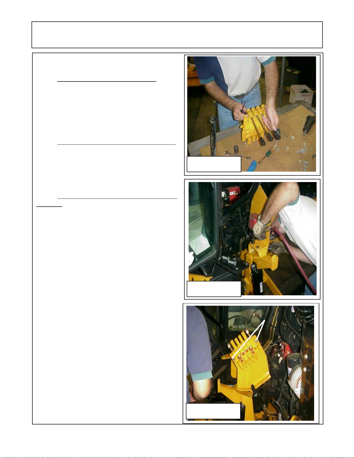
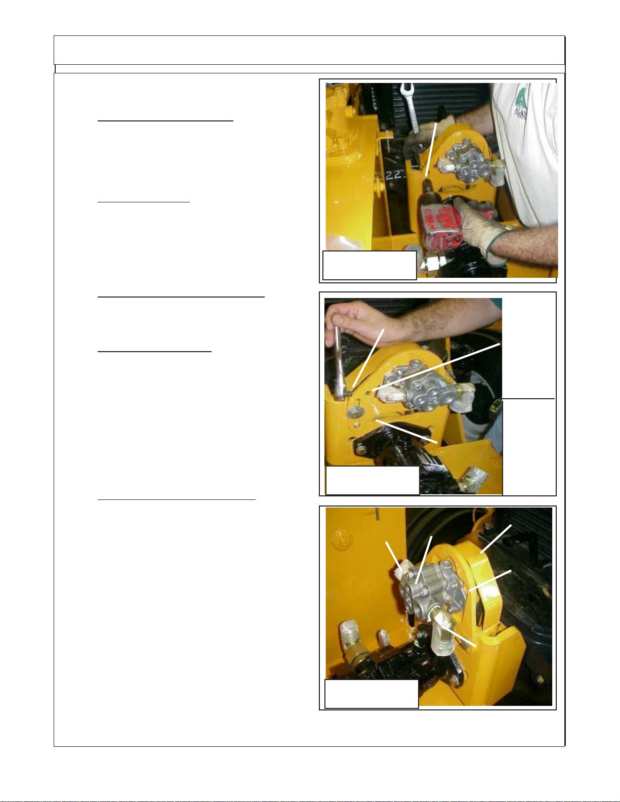
Prepare 4 Spool Control Valve:
1. Remove standard control Handles. When
using the remote control cables and handles the
standard handles must be removed and discarded.
This is done by removing the C-Clips and pins that
hold the handles to the valve body and the C-clips
and pins that hold handles to the spools. (See Figure
12)
2. Bolt Valve Mounting Bracket to Mainframe .
The valve mounting bracket is bolted to the Right
Hand side of the tractor. It is bolted to the mainframe.
There are two different sets of hole in valve mounting
bracket, this allows the location of the valve to be
varied.
3. Install The Cylinder Control Valve to Valve
Bracket. The control valve is mount to the valve
bracket using two bolts. These two bolts is all that will
be needed to mount valve to valve bracket. (See
Figure 14).
Figure 12
Figure 13
Figure 14
Interstater (NH TS-100A , 115A , 125A & 135A Asy. Manual) 06/04
© 2004 Alamo Group Inc.
Page 2 - 5
Valve mounting bolts (2
used)
Page 16

NOTES
Interstater (NH TS-100A , 115A , 125A & 135A Asy. Manual) 06/04
© 2004 Alamo Group Inc.
Page 2 - 6
Page 17

Section 3
INTERSTATER
New Holland
TS100A, TS115A
TS125A, TS135A
Tractor
Pump, Driveshaft &
Hyd. Tank
Interstater (NH TS-100A , 115A , 125A & 135A Asy. Manual) 06/04
© 2004 Alamo Group Inc.
Section 3 - 1
Page 18
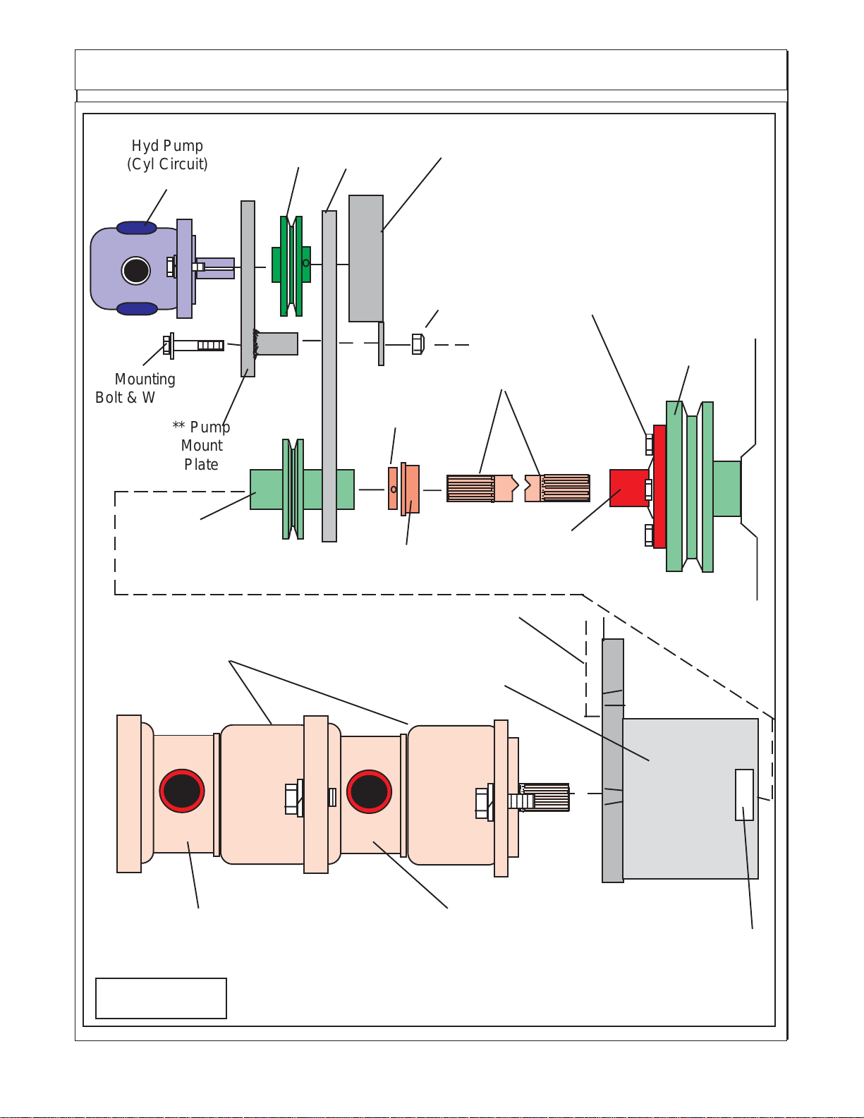
Pump & Driveshaft Schematic
6
6
3
3
Hyd Pump
(Cyl Circuit)
Mounting
Bolt & Washer
** Pump
Mount
Plate
Drive Pulley &
Splined Sleeve
Weldment
2345
Driven
Pulley
Drive
Belt
* Bearing
Collar
* Driveshaft
Bearing
Shield
Locknut
Pulley Adapter
Mounting Bolts
Tractor Engine
Pulley
Driveshaft
Pulley
Adapter
** Small (Cyl Hyd) Pump Mount Plate mounts here
Tandem Pump for Dual Wings
Pump Mount
Weldment
2
2
Right Wing PumpLeft Wing Pump
Figure 1
2345
* Driveshaft Bearing installs into
pump mount weldment here.
Interstater (NH TS-100A , 115A , 125A & 135A Asy. Manual) 06/04
© 2004 Alamo Group Inc.
Section 3 - 2
Page 19
Pump - Driveshaft - Hyd tank
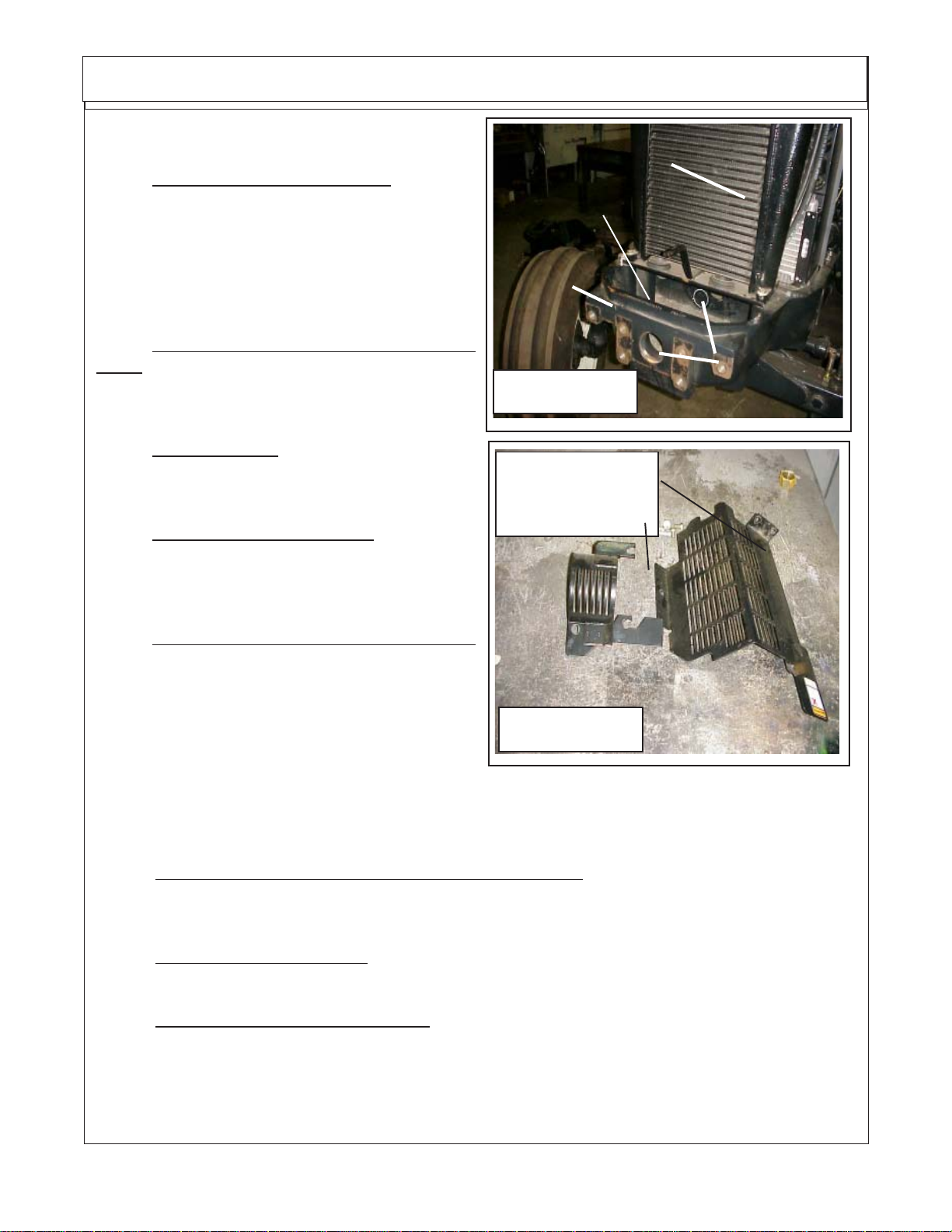
Install Driveshaft, Pump & Tank:
1. Gain Access to Tractor Engine. Raise the
hood of the tractor to revel the tractor engine (See
Figure 2). Remove the engine guards on the left
hand side of tractor (See Figure 3). This will allow
you access to the Tractor Crankshaft Pulley. (See
Figure 1). Remove the plate under After cooler which
will make installing driveshaft easier.
Air After-Cooler
Cover removed
Tractor
Bolster
2. Bolt Pulley Adapter to Engine Crankshaft
Pulley. Bolt the pulley adapter to the to the crankshaft
pulley with the supplied bolts. Make certain the bolts
used are not to long or to short (See Figure 1).
3. Install Driveshaft. Insert driveshaft into crank-
shaft pulley, both splined ends are the same so it will
not matter which end is inserted.
4. Install pump Mount Weldment. Bolt the pump
mount weldment to the front bolster of the tractor.
The driveshaft will be sicking through the hole in the
pump mount weldment. (See Figure 1)
5. Install Driveshaft Bearing & Bearing Collar.
Slide the bearing onto the driveshaft until the bearing
is seated into the inner hole of the pump mount
weldment where the driveshaft comes through. Slide
the bearing collar onto driveshaft until seated against
bearing. Making certain that driveshaft is seated into
crankshaft pulley adapter tighten setscrew for bearing collar. (See Figure 1)
Figure 2
LH Side Engine
Guards Removed
From Tractor
Figure 3
Existing Holes
have rubber
Plugs in them
6. Install Drive pulley & Splined sleeve weldment. The drive pulley weldment and drive belt will have
to be installed at the same time. If the drive belt is not installed now you will not be able to later.
7. Install Hydraulic Pump (Pumps to operate Wing Motors). Install the Tandem Pump (single
pump if only one wing.) By aligning the splines of the pump shaft with the splines of the drive pulley &
splined sleeve weldment. Push the pump on till the pump is seated into the pump mount weldment.
8. Install Pump Retaining Bolts. Install the two bolts that retain the Left & Right wing pump(s) to
the pump mount weldment and tighten them. (See Figure 1)
9. Install Small Pump (Hyd Cyl System). The Hyd Cyl operate from a small pump bolted above the
tandem pump. (See Figure 1) Bolt the Pump onto the Small Pump Mount plate with the two mounting
bolts. Install the driven pulley onto the pump, make certain to install the key in pump shaft. DO NOT
tighten the setscrews in pulley until later. Slide the Drive Belt onto driven pulley and align the pump mount
plate with the holes in the pump mount weldment, use Flat washers on bolts to mount to pump mount
weldment (See Figure 4). DO NOT Tighten these bolts yet.
Interstater (NH TS-100A , 115A , 125A & 135A Asy. Manual) 06/04
© 2004 Alamo Group Inc.
Section 3 - 3
Page 20
Pump - Driveshaft - Hyd tank
Install Driveshaft, Pump & Tank:
(continued)
10. Small Pump Belt Adjustment. The belt Guard
is retained with the same bolts that mount the pump
plate and the same bolts that are used to adjust the
drive belt. For now do not install the belt guard. Snug
these bolts for now but do not tighten them
Use
Flatwasher
here
11. Align driven pulley. The driven pulley on the
small pump will need to be aligned with the drive
pulley below it. Slide the pulley on the pump shaft on
or off to align with the drive pulley on the main
driveshaft. Tighten setscrews in Driven pulley when
aligned.
Figure 4
12. Install Belt Guard on Small Pump. With the
driven pulley aligned install the belt guard and reinstall the retaining nuts.
13. Adjust the Belt Tension. Look on the mount
plate you will see a 3/8" square hole above the slotted
hole (See Figure 5). Using a 3/8" drive ratchet in the
3/8" hole pull up on the ratchet until the belt is
adjusted. Do not over tighten the belt, it should be
tightened to firm. Holding the tension on the belt
tighten the mounting bolts. You may need to get
someone to help you with this. DO NOT over tighten
the Drive Belt as it could damage the pump. (See
Figure 6)
Figure 5
3/8"
Ratchet
Slotted
Adjusting
Hole
3/8"
square
hole
Small
Hyd
Pump
for Hyd
Cyl
Supply
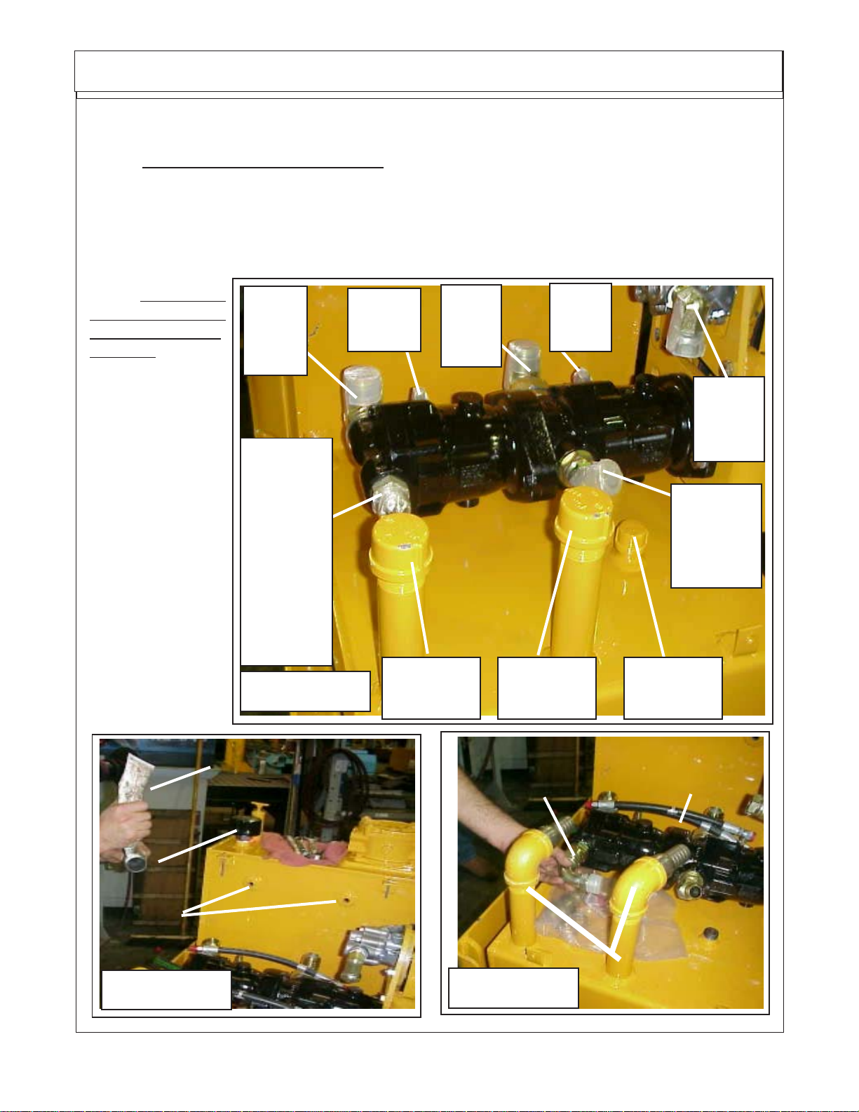
14. Prepare Tandem Pump Fittings DO NOT
remove any caps or plugs on hydraulic hoses or
connections until you are connecting them, this will
keep dirt out. The Tandem Pump will need to be
prepared for connecting the hoses. There are fittings
that must be changed. The Fittings in the tandem
pump should already be installed when you receive
it from the factory (See Figure 7). The Pressure Out
Port to LH Wing from outer Tandem half of pump
straight out fitting will need to be change to a 90
degree elbow fitting (See Figure 7 ). The Two large
caps on the tank suction ports will need to be
replaced with two elbow fittings and hose barbs (See
Figure 7, 8 & 9). Coat the fittings that screw into
pumps and tank with a pipe sealer (NOT Teflon
Tape), do not put excess sealer on OD of fittings and
none on ID of fittings (See Figure 7). Install the elbow
fitting into the pressure port of the LH Motor Pump (outer pump on tandem pump) with the supplied
elbow (See Figure 9)
Out
Pressure
Side
Figure 6
Small
Pump
Belt
Guard
Pump
Mount
Plate
In
Suction
Side
Interstater (NH TS-100A , 115A , 125A & 135A Asy. Manual) 06/04
© 2004 Alamo Group Inc.
Section 3 - 4
Page 21
Pump - Driveshaft - Hyd tank
Install Driveshaft, Pump & Tank: (continued)
15. Connect Pump Case Drain To Tank. On the Right Hand side of the tandem pump there will be
two small elbows, these are the case drains for the pumps. On the side of the tank and above theses
elbows there will be two small plugs screwed into tank. Remove these plugs and install the pipe thread
end of the two small hose after coating the threads with pipe sealer. Connect the other end of the hose
to the elbows on the side of the pumps. NOTE: Only the Tandem pump will have case drains, the smaller
pump used to power the hydraulic cylinder system will not use a case drain. (See Figure 9 & 11)
16. The small
pump used to supply
the cylinder hydraulic system will have a
short hose that connects to the small
pump and to the tank
suction port that is in
the tank exclusively
for the small pump.
This hose needs to
be cut to fit, do not
install with any kinks
in hose. (See Figure
6 & 7) which shows
these ports.Make
certain the Elbow
(pressure port of
outer tandem pump
(See Figure 9) is installed and tightened
pointing to the rear of
the pump.
Suction
Port
From
Tank
Pressure
Out Port
To LH
Wing
Motor,
Straight
Fitting
shown will
be changed
to Elbow
Fitting
Figure 7
Case
Drain To
Tank
Tank Suction
Port, LH
Wing Pump
Suction
Port
From
Tank
Case
Drain To
Tank
Tank Suction
Port, RH
Wing Pump
Suction
Port
From
Tank
Pressure
Out Port
To RH
Wing Motor
Tank Suction
Port, Small
Pump
Pipe Sealer
Tube
Fitting with
Pipe Thread
Return Tank
Ports for
Tandem
Pump Case
Drains
Figure 8
Interstater (NH TS-100A , 115A , 125A & 135A Asy. Manual) 06/04
© 2004 Alamo Group Inc.
Section 3 - 5
Change to
Elbow Fitting
Figure 9
Case drain
Hoses laying
here for now
Install 90 degree
elbows and hose
barbs to suctiion
tubes from tank
Page 22
Pump - Driveshaft - Hyd tank
Install Driveshaft, Pump & Tank:
(continued)
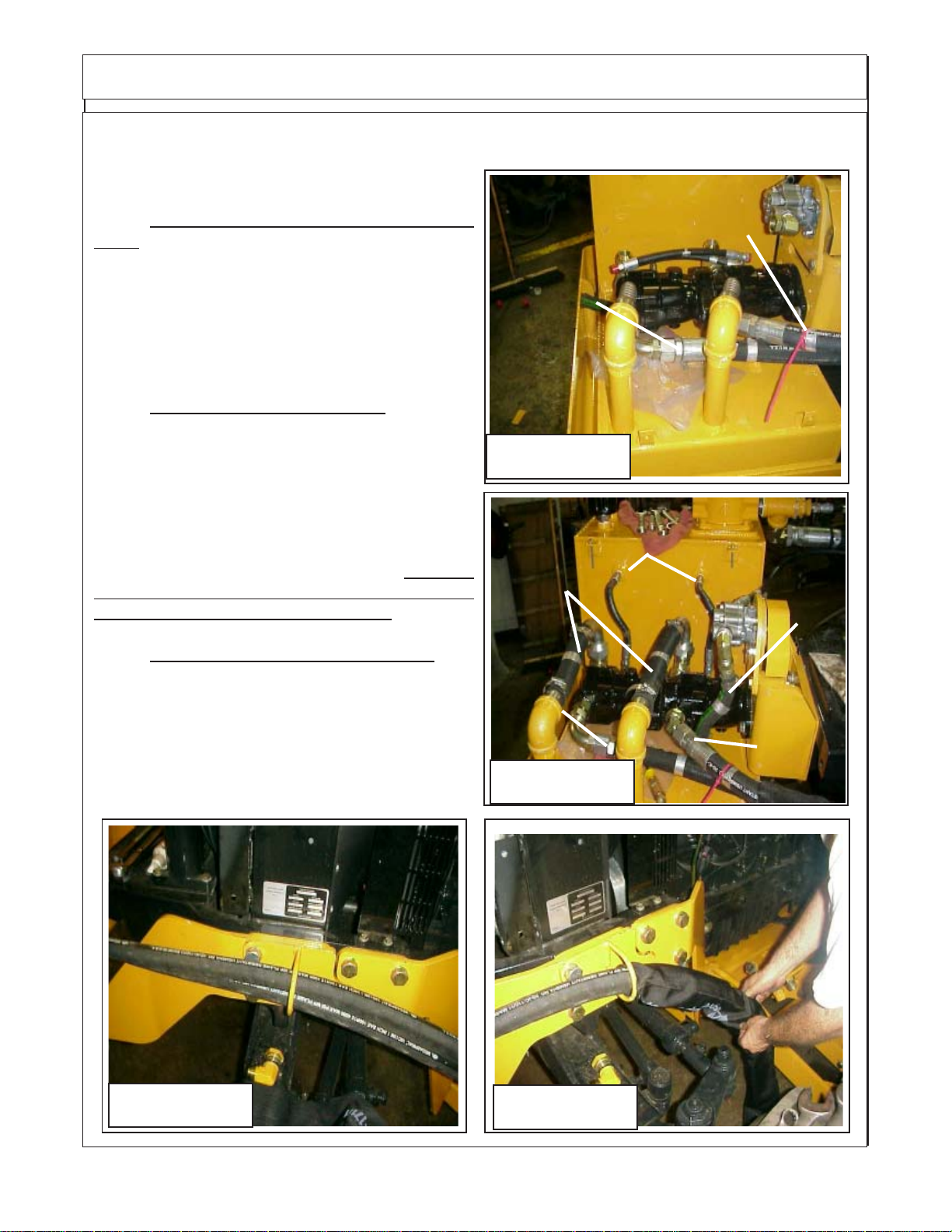
17. Connect Motor Pressure Supply Hoses to
Pump. The Tandem Pump has two pressure hoses.
The Rear (closest to Tractor Engine) it the supply for
the RH Wing Motor. The Outer Pump is the LH Wing
Motor Pressure Supply. The hose for the RH Wing
should be marked with a red plastic tie on it, the other
hose is not Identified. Connect these two hoses at
the pump now.
18. Connect Pump Suction Hoses. The Case
drain hoses should already be connected, if not
connect them now. Hoses & Fittings with Pipe
thread will need a thread sealer used (do not use
excess sealer and no sealer on ID of fittings). The
Tandem Pump Suction hoses will be sent longer
than needed and will need to be cut to fit. (See Figure
11). The Aux. Pump Suction hose will need to be cut
to fit and connected now (See Figure 11).
have any kinks in the suction hose, it will starve the
pump of oil causing damage to system.
19. Cover Pressure Hoses with Sleeving. With
the two pressure hoses run the hose retaining ring
(See Figure 12) bolted to the side of tank rails slide
the hose sleeving up over the pressure hoses (See
Figure 13). Slide the sleeving over hoses and through
the hose retaining ring. Slide sleeving up until it is
about 2 inches past the edge of the hydraulic tank.
DO NOT
Pressure
Hose to LH
Wing Motor
Figure 10
Case
Tandem
Pump
Suction
Hoses
LH Wing
Pressure
Hose
Drain
Hoses
Figure 11
Pressure Hose to
RH Wing Motor with
Red Plastic Tie
Aux
Pump
Suc-
tion
Hose
RH Wing
Pressure
Hose
Figure 12 Figure 13
Interstater (NH TS-100A , 115A , 125A & 135A Asy. Manual) 06/04
© 2004 Alamo Group Inc.
Section 3 - 6
Page 23

Pump - Driveshaft - Hyd tank
Install Driveshaft, Pump & Tank:
(continued)
20. Change Straight Bulkhead fitting to an
Elbow Fitting. There is a straight bulkhead fitting installed into main frame crossmember that
should be changed to a 90 " elbow< (See Figure
14,15,16 & 17).
21. Connect Motor Pressure Supply Hoses to
Main Frame Cross Member. The Tandem Pump
has two pressure hoses. The Rear (closest to
Tractor Engine) it the supply for the RH Wing Motor.
The Outer Pump is the LH Wing Motor Pressure
Supply. The hose for the RH Wing should be marked
with a red plastic tie on it, the other hose is not
Identified. Connect these two hoses at the Main
frame crossmember now (See Figure 16 & 17)
22. Connect Hoses to correct Bulkhead fittings
is important here . The Pressure hoses MUST be
connected correctly to the correct bulkhead fitting. If
they are not they will damage the head cooling tubes
and/or other components. DO NOT connect any
hoses until instructed to do so. Always double check
the hose routing to make sure they are correct.
Remove this
Straight Bulk
Head Fitting &
Replace it with
an Elbow
Figure 14
Install this Elbow
Bulk Head Fitting in
place of straight one.
LH Wing Side Of
Tractor
Figure 15
Install Pressure Hose from Tandem Pump
to Bulk head fitting here for LH Wing
Motor
Install Pressure Hose
from Tandem Pump to
Bulk head fitting here for
RH Wing Motor
Figure 16
Interstater (NH TS-100A , 115A , 125A & 135A Asy. Manual) 06/04
LH Wing Side Of
Tractor
Pressure Hose f/ Tandem
Pump to Bulk head fitting here
, LH Wing Motor
Figure 17
LH Wing Side Of
Tractor
Pressure Hose f/ Tandem Pump to Bulk
head fitting here , RH
Wing Motor
© 2004 Alamo Group Inc.
Section 3 - 7
Page 24

Pump - Driveshaft - Hyd tank
Install Driveshaft, Pump & Tank:
(continued)
23. Install Hose Fittings into Return Filter in Tank.
There is a return filter in the top of the RH side of tank.
In the end of the filter housing install a Tee Fitting with
an Elbow in it, the tee fitting should point outward as
seen in figure 19. In the end of the Tee there will be
reducer to allow the installing of a smaller hose. This
reducer is where the return hose from the control
valve will connect (See Figure 18, 19 & 25). The
elbow fitting in the tee should be turned downward at
approx a 45 degree angle (see Figure 19 & 25) .
Installing these fittings in this way will allow the oil
cooler to be slid out for maintenance without hydraulic hoses interfering with cooler.
24. Install Return Filter Pressure Gauge. The
return filter pressure gauge screws into the side of
the return filter housing. This gauge is a low pressure gauge that is marked in green and red areas.
(See Figure 19). The Oil Pressure return gauge has
a rubbery tip on top of it, the tip till have to have the tip
of it cutoff. Using a utility knife (or suitable knife) cut
the tip off now (See Figure 20). This will need to be
done before unit is run.
Tank Return
Filter
Figure 18
Return Hose
Return Hose
from 4 Spool
Control valve
Port Marked "T"
Oil Level
Sight Glass
Oil Temperature
Gauge
Pipe
Tee
from Wing
Motors
Reducer
Fittting
Elbow
Fitting
Oil Level
Sight Glass
Return
Pressure
Gauge
25. Install the Oil Level Sight Glass. The Oil Level
sight Glass screws into the Hydraulic tank. This is to
covered with oil when tank is a at operating level.
(See Figure 18 & 19)
Figure 19
Cyl. Control
valve Supply
Pump
Figure 20
Interstater (NH TS-100A , 115A , 125A & 135A Asy. Manual) 06/04
Figure 21
To Control Valve, Pressure
Line ("P" Port on Valve)
Tank
Suction
Line
© 2004 Alamo Group Inc.
Section 3 - 8
Page 25

Pump - Driveshaft - Hyd tank
Install Driveshaft, Pump & Tank: (continued)
26. Install the small pump pressure hose to
pump. The pressure hose connects to the RH side
of the small pump and is run down the RH side of the
frame with the return hoses (See Figure 21)
27. Install sleeving over the return hoses from
heads and control valve and Control valve Pressure
Hose. Slide the three hoses through the sleeving.
Slide the hoses with the sleeving through the hose
support ring bolted to the side of the tractor. Tie the
sleeving using plastic ties around the hoses to keep
it from moving (See Figure 22). Tie the sleeving with
plastic ties around the pressure hose on the LH side
of tractor (See Figure 13)
28. Install return hose to cross member and
Hoses to Control Valve. Connect the return hose to
the cross member on right hand side of main frame
crossmember (See Figure 23). The other end will
connect to the return filter Tee fitting (See Figure 24)
29. Connect Pressure & Return Hose to Cylin-
der Control valve. Connect the pressure hose running from the RH side of small pump to RH Top side
of control valve, The port will be marked with a "P"
cast into it, the other end is connected to the small
supply pump (See Figure 21). Connect the return
hose that is connected to the Tee Fitting of the return
filter to the Return side of the control valve with a "T"
cast into it (See Figure 24 & 25)
"In" Pressure
Side
"Out" Return
Side
Figure 22
Pressure Hose
to RH Wing
Motor
Figure 23
Return Hose
from Wing
Motors to Tank
Return Line From
RH Wing Deck
Cooling Tanks
Return Hose from
Hyd Valve "T" Port
Figure 24
Interstater (NH TS-100A , 115A , 125A & 135A Asy. Manual) 06/04
© 2004 Alamo Group Inc.
Figure 25
Section 3 - 9
Return Hose from Main
Frame Crossmember
(Motor Return)
Page 26

NOTES
Interstater (NH TS-100A , 115A , 125A & 135A Asy. Manual) 06/04
© 2004 Alamo Group Inc.
Section 3 - 10
Page 27

Section 4
INTERSTATER
New Holland
TS100A, TS115A
TS125A, TS135A
Remote Control Cable
Connections
Interstater (NH TS-100A , 115A , 125A & 135A Asy. Manual) 06/04
Tractor
© 2004 Alamo Group Inc.
Page 4 - 1
Page 28

Remote Control Cable Connections
Remote Control Cable Connections Cab Tractor:
1. Control Valve Cable Clips. Locate the four
cable mounting clips and four roll pins (shown laying
on muffler bracket for illustration only in Figure 1).
Start the roll pins into the clips as shown through one
side only (See Figure 1). Insert the Remote Cable
through the Control Valve Mount Bracket (See Figure 2). Install the large cable retaining / Adjusting nut
onto threaded portion of cable housing (See Figure
2). DO NOT tighten this large nut until later. On the
tip of the threaded end of the cable there is a 1/4" nut.
Screw this nut down onto cable. Insert the cable clip
down over threaded cable end (See Figure 3). Find
the four 1/4" nut supplied, install one onto end of
cable down into clip. This nut should be screwed
onto cable at least the thickness of the nut, do not
screw it on so far that it will interfere with the
operation of the cable. Using the nut that was already
on the cable screw the nut out until it is against the
clip from the bottom side, tightening this nut against
clip will lock the other nut inside of clip. (See Figure
3).
Cable Mounting Clips &
Roll Pins (Qty 4 ea.)
Figure 1
Screw this
small nut down
onto cable
2. Connect Clip to Valve Spool. Turn the clip
and the valve spool to where the hole in the clip and
the hole in the clip are aligned. Using a hammer drive
the roll pin through the hole in the spool and through
the other side of clip (See Figure 4) . Make certain to
keep the clip aligned when driving pin in. Turn the clip
and spool as shown (See Figure 5), Continue this
with the other 4 cables and clips (See Figure 6).
3. Connect Cylinder Hoses to Valve. There are
six cylinder hoses that connect to Control Valve.
One Pressure "P" hose and one Tank "T" hose.
These hoses are connected as follows (See Figure
7 , 9 & 23)
1. Tilt Cyl. Rod End RH Wing.
2. Tilt Cyl, Butt End RH Wing.
3. Lift Cyl. Rod End, RH Wing.
4. Tilt Cyl. Rod End LH Wing.
5. Tilt Cyl. Butt End LH Wing.
6. Lift Cyl. Rod End LH Wing.
7. "P" Pressure Hose from Pump
8. "T" Return Hose To Tank
Connect hoses with elbow pointing down (See Figure 8)
Figure 2
Figure 3
Interstater (NH TS-100A , 115A , 125A & 135A Asy. Manual) 06/04
© 2004 Alamo Group Inc.
Page 4 - 2
Page 29

Remote Control Cable Connections
Remote Control Cable Connections: (continued)
Figure 4
Figure 6
Control Valve Hoses
Figure 5
7
1
2
Figure 7
Vent Plug
8
4
5
6
3
1
Figure 8
Interstater (NH TS-100A , 115A , 125A & 135A Asy. Manual) 06/04
© 2004 Alamo Group Inc.
Page 4 - 3
Figure 9
2
3
Page 30

Remote Control Cable Connections (Cab Tractor)
Remote Control Cable Connections Cab Tractor:
1. Install Remote Cable Control Lever Mount-
ing Bracket In Cab Tractor. Locate the four existing
threaded holes that are in the RH side on the cab
door post (See Figure 10). The Control Lever Mounting bracket will bolt to two of these holes. Align the
matching holes of the mounting bracket with two of
the threaded door post holes. Install the two mounting bolts through bracket and into door post (See
Figure 11)
2. Cut Hole Through Rubber Floor Mat and Cab
Floor. Some Cabs may already have a hole through
floor, pull up rubber mat and check before cutting
hole. It is recommended that a 2" round hole be cut
to keep all the cables and wire harness together and
smoothly coming up through floor. Before a hole is
cut in floor check the under side to make certain that
the hole saw is not going to damage any of the
components under the floor. Make certain that the
hole cut is far enough over that it will not interfere with
operators foot room. Cut hole through floor mat and
floor using a round 2" hole saw (See Figure 12). After
you cut the rubber mat with the hole saw pull the
piece of rubber out of saw, this will make it easier to
cut through the floor. (See Figure 12)
3. Install Cable / Wire Harness Boot Cover. The
Boot cover will be modified, using a knife cut an "X"
shaped cut across the small hole at the top. This cut
will be cut back approx 1/2" from original hole. Using
the 4 screws screw the cover to the rubber mat.
(See Figure 13 & 14)
Existing Threaded holes in
RH Door Frame of Cab
Figure 10
Control Lever
Mounting Bracket
Figure 11
2" Hole Saw
Rubber Floor Mat
Figure 12
Interstater (NH TS-100A , 115A , 125A & 135A Asy. Manual) 06/04
© 2004 Alamo Group Inc.
Page 4 - 4
Figure 13
Page 31

Remote Control Cable Connections (Cab Tractor)
Remote Control Cable Connections Cab Tractor: (continued)
4. Install Wire Harness through floor and
boot. The Wire harness will come to you with the on
/ off switches attached, these switches will need to
be removes to Push the Wire Harness up through
the floor and boot cover (See Figure 15 & 18).
5. Insert Cables up through Boot Cover. Mark
the cables as to which is which on the control valve
as they need to be connected in the same order on
the inside of the cab as they are connected to the
control valve (See Figure 17)
Screw the cover to the
Rubber Floor Mat with
the screws furnished.
Figure 14
Control cable
Wire Harness
Cable Cover
Boot
Figure 15
Mark on Cable
to reference
which it is on
the control
valve
Figure 17
Interstater (NH TS-100A , 115A , 125A & 135A Asy. Manual) 06/04
© 2004 Alamo Group Inc.
Page 4 - 5
Figure 16
Switches unpluged and
removed to run up
through the Fllot and
Figure 18
boot cover
Page 32

Remote Control Cable Connections (ROPS Tractor)
Remote Control Cable Connections ROPS Tractor:
1. Install Valve Stand to Tractor on ROPS Trac-
tor only. Attach Valve Stand to the top of the Right Lift
Cylinder Support with (3) 1/2" x 1-1/2" bolts, and (3)
1/2" locknuts (See Figure 19).
2. Attcah Valve Stand to Valve Mount Bracket.
Attach Valve Stand to the Valve Mount Bracket with
(2) 3/8" x 1-1/4" bolts and (2) 3/8" locknuts (See
Figure 20).
3. Attach Control Valve to the Valve Stand.
Attach Control Valve to the Valve Stand with (2) 3/8"
x 1" bolts, (2) 3/8" locknuts. Attach the Top Cover
and the Bottom Cover to the Valve Mount Bracket
with (8) 3/8" x 1" bolts, (8) 3/8 washers and (8) 3/8"
locknuts (See Figure 21).
4. Install Mower Wing ON / Off Switches. Make
certain to install connector so that larger brown
wires are located on bottom poles of switch. This
applies to Dual Wing and Single Wing applications
Figure 19
Figure 20
MOWER ON/OFF
SWITCH
Figure 22
Interstater (NH TS-100A , 115A , 125A & 135A Asy. Manual) 06/04
© 2004 Alamo Group Inc.
Page 4 - 6
Left or Right
On / Off
Brown
Figure 22
Figure 21
Switch
Red
Red
*
Brn
Brn
Plug as seen
from back
where wires
plug in
*
White (for LH Wing Switch) OR
Yellow (for RH Wing Switch)
Page 33

Remote Control Cable Connections
Remote Control Cable Connections:
(continued)
6. Each controller assembly comes fully as-
sembled. All required hardware etc. is included.
The control cables are not included with the control
handles and should be ordered separately. The
Controller must face forward as shown or controls
will be backward (See Figure 23)
7. To attach the cable, manipulate the controller
handle so that the attachment nut is exposed as
shown. Remove the lower most nut and screw
from the controller housing.
Thread the cable nut into the controller attachment
nut and tighten. (See Figure 24)
8. Allow the controller handle to return to neutral.
Slide the cable guide tube into the control housing
and reinstall and tighten the housing screw.
9. Check the operation of the spool, cable and
controller. Some adjustment at the valve end may
be required too ensure that the spool returns to
neutral when the controller is in the neutral position.
(See Figure 25)
Tractor Front
Figure 23
10. The control lever assemblies utilizes a small
spring to make up for free play in the cable to valve
connection. The control valve spool spring provides the centering capabilities of the controller
and the valve spool. Lack of centering at the
controller is normally attributed to poor adjustment at the valve to cable connection or
binding of the cables due to poor routing.
11. The control lever assemblies will bolt to-
gether to form a group of handles, there will be 4
handles bolted together along with the switch mounting brackets. (See Figure 26 & 27) The switches
will mount to these brackets. Dual Wings models
will have two switches. The switch for the left wing
mount on the left and switch for the right wing
mounts on the right (See Figure 26 & 27). The
same two long bolts that go through cable control
handles will go through switch brackets.
Interstater (NH TS-100A , 115A , 125A & 135A Asy. Manual) 06/04
© 2004 Alamo Group Inc.
Page 4 - 7
Figure 24
Figure 25
Page 34

Remote Control Cable Connections
Remote Control Cable Connections: (continued)
12. Adjust Handles. The handles will have
some adjustment to the as the Mounting bracket
the handles bolt to will have slotted holes to allow
the handles to be rotated to position the handles
straight up. (See Figures 11, 26 & 27) Cab Model
Shown.
13. Tie Cables and Wire Harness together. Tie
the cables and Wire Harness together with plastic
ties inside the cab and outside the cab. This will
keep them from moving around. Cab Mdel Shown.
14. Control Valve Hydraulic Schematic. The
schematic shows the routing of hoses to the
cylinder control valve. The cables must be connected in pattern as shown (See Figure 27 & 29)
in order for the proper function to match instructions. Cab or Rops model are the same (See
Figure 29)
Figure 26
Left Wing
Tilt Cyl
Control
Switch
Mounting
Brackets
Left Wing
Lift Cyl
Control
Right Wing
Lift Cyl
Control
Right Wing
Tilt Cyl
Control
Left Wing
"On" / "Off" Switch
Figure 27
Interstater (NH TS-100A , 115A , 125A & 135A Asy. Manual) 06/04
© 2004 Alamo Group Inc.
Page 4 - 8
Right Wing
"On" / "Off" Switch
Page 35

Remote Control Cable Connections
Remote Control Cable
Connections: (continued)
15. Adjust Handles. Handles for thr Cab
Model or Rops Nodel will adjust about the
same.The handles will have some adjustment to them as the retaining nut on the Valve
end of the cable is tightened. Tighten these
retaining nuts now. (See Figure 28).
16. Check Hydraulic Hose Routing. Shown
below is the routing of the hydraulic Cylinder &
Control Valve. Double check these before
running Unit. (See Figure 29)
○○○○○○○○○○○○○○○○○○○○○
○○○
Figure 28
Cable Retaining
Nuts (Qty 4)
"P" Pressure Port
○○○○○○○○
○○○○○○○○○○○○○○○○○○○○○○○
○○○○○○○○○○○
○○○○○○○○○○○○○
○○○○○○○○○○○○○○○○○○○○○○○○○○
○○○○○○○○○○
○○○○○○○○○○○○○○○○
○○○○○○○○○○○
○○○○○○○
○○○○○○○○○○○○○○
○○○○○○○○○○○○○○○○○○○○○
○○○○○○○○○○○○○○○
Vent
○○
○○○○○
Plug
Vent
○○○○○
Plug
○○○○
○○○
"T" Tank Return Port
○○○○○○○○○○○○○○
○○○
○○○
○○○○○
○○○○○○○○○○○○○○○○○○○○○○○○○○○
○○○○○○○○○○○○○○○
RH Wing
Tilt Cylinder
RH Wing
Lift Cylinder
Lift Cylinder
Figure 29
Interstater (NH TS-100A , 115A , 125A & 135A Asy. Manual) 06/04
© 2004 Alamo Group Inc.
Page 4 - 9
LH Wing
KH Wing
Tilt Cylinder
Page 36

Wire Harness Connections
Wire Harness Connections:
1. Connect Wire Harness to Tractor
Starter. The wires to the starter from the off on
switches will need to be connected to the
tractor near the started connections (See Figure 30, 31 & 32). All see the wire / harness
schematic on the following pages. Consult the
Tractor Repair Manual for wiring schematic of
Tractor.
Wire Harness
Wires
Tractor Starter
2. Check all Wire Harness Routing. Inspect
all of the wire harness, make certain the all
portions of wire harness that have been installed is tied up and out of the way of folding
components or any thing that may damage
them (See Figure 31 & 32).
3. Wires from the safety switch must be
routed close to cutterhousing sidesheet and
lift frame pivot points. This will prevent wires
from being stretched and broken when
cutterhousing is raised or lowered to maximum positons.
NOTE: Route wires in such a manner to
prevent interference with the operation of tractor or INTERSTATER. Ensure that wires DO
NOT lay against anything which could wear
through insulation and cause a short circuit.
After connecting all wires, wrap wires with
flexguard tubing. Neatly gather hydraulic
hoses and flexguard tubing and strap together
using plastic ties.
Figure 30
Figure 31
Interstater (NH TS-100A , 115A , 125A & 135A Asy. Manual) 06/04
© 2004 Alamo Group Inc.
Page 4 - 10
Page 37

Wiring Harness Schematic
Figure 32
Left Wing Motor
Solenoid Valve
Black/Wht
Brown
Brown
Red
Black
Fuse
White
Left
Switch
Cavity
Plug
Red
Right
Switch
DOUBLE WING MOWER
SHOWN
(Single Wings have only the Right
Wing Motor Solenoid Valve
harness)
3 Terminal
Connector
Right Wing Motor
Solenoid Valve
Yellow
Red
Left
Switch
Brown
Black/Wht
Yellow
Right
Switch
White
Yellow
3 Terminal
Connector
YellowWhite
Left Wing Safety Cut-off Switch
White
Black
B/W
Left Wing
Motor Solenoid
Valve
Interstater (NH TS-100A , 115A , 125A & 135A Asy. Manual) 06/04
© 2004 Alamo Group Inc.
#1
#2
White
Black/White
Black
Page 4 - 11
Right Wing Safety Cut-off Switch
Brown (Start Terminal)
Brown (Starter Solenoid)
Red (to Accessory Terminal)
Black (Ground @ Tractor Starter)
Black
#1
#2
Right Wing
Motor Solenoid
Valve
Page 38

NOTES
Interstater (NH TS-100A , 115A , 125A & 135A Asy. Manual) 06/04
© 2004 Alamo Group Inc.
Page 4 - 12
Page 39

Section 5
INTERSTATER
New Holland
TS100A, TS115A
TS125A, TS135A
Tractor Exhaust
Modification
Interstater (NH TS-100A , 115A , 125A & 135A Asy. Manual) 06/04
Tractor
© 2004 Alamo Group Inc.
Page 5 - 1
Page 40

Tractor Exhaust Modification
Modify Exhaust on Tractor:
1. Modify Tractor Factory Exhaust
System. The Exhaust of the tractor must be
modified to move exhaust (muffler) in closer (8-1/
2" Closer) to the hood of tractor to give the
Interstater clearance when wing is folded into the
transport position. This should be done before
the wing mower is mounted.
2. Remove Old Exhaust System. The stock
factory muffler is removed first, this will be saved
as it will be reused after the exhaust pipe to turbo
has been changed.
3. Remove Existing Exhaust Pipe to Turbo &
Existing Exhaust Mounting Bracket. There are
four socket head bolts that hold the exhaust flange
to the turbo, these will need to be removed completely. There is a stock mounting bracket located
at the outer corner of the cab that supports the
exhaust pipe. This bracket will be removed also.
(See Figure 2). Lay the Bracket and exhaust pipe
aside as the kit will include replace Pipe, Bracket
and Fasteners.
Stock Exhaust Pipe to
Turbo Components
Figure 1
Stock Exhaust
Mounting Bracket
at corner of Cab
4.
pipe, mount bracket, clamp and flange mounting
bolt will be included in Exhaust Relocation Kit P/N
02980916
Part No. Qty Description
02980933 1 Exhaust Brkt Wldmnt
02980917 1 Turbo Downpipe Wldmnt
02959132 2 3-1/2" Exhaust Clamp
02980728 3 Bolt, Hex Head 12 mm X 30 mm
701513C 3 Flat washer, 12 mm
00754566 3 Lockwasher, 12 mm
5. Install Exhaust Turbo Pipe. The new Exhaust pipe will come as a welded assembly (P/N
02980917) using the original flange and bolts.
Tighten the four flange bolts that retain the turbo
downpipe to the turbo.
Exhaust Relocation Kit. The new Exhaust
Figure 2
Turbo Down Tube
Mounting Flange
Turbo
Downpipe
Weldment
Figure 3
4 Socket Head
bolts for
Exhaust Flange
at Turbo
Interstater (NH TS-100A , 115A , 125A & 135A Asy. Manual) 06/04
© 2004 Alamo Group Inc.
Page 5 - 2
Page 41

Tractor Exhaust Modification
Modify Exhaust on Tractor:
(continued)
6. Install Exhaust Mount Bracket. The new
Exhaust mounting Bracket Weldment (See
Figure 4 & 5 P/N 02980649) must be installed to
mount the new Turbo Downpipe to using the 3-1/
2" Clamp (P/N 02959132) to mount the Downpipe
the new Exhaust mounting bracket. Note: The
New Exhaust Bracket has slotted holes in it that
are not shown in the angle that figure 4 is showing
the weldment. There are 3 Bolts and lockwashers
used to mount this weldment.
New
Exhaust
Mntg Brkt
at corner
of Cab
7. Reinstall Muffler. Reinstall the muffler
using the existing hardware for the muffler. Turn
the tip of the muffler toward the LH side of tractor
as shown in Figure 6 if it is not already. Muffler
should now be 8-1/2" inward from the stock location, this is a must for clearance of the Wing when
folded in the up ( Transport) position. Note figure
6 show a high frame installed, this is for reference
only, the muffler should be modified before frame
and boom are mounted.
8. Muffler Clearance. Make certain that the
hoses, wiring and other components are not touching the muffler. Make certain that all shields if any
are replaced around muffler and exhaust pipe.
9. The LH Outside Rear View Mirror. The Left
Hand outside rear view mirror will have to be
removed as the boom will not clear it mounted to
the cab. Any lights and/or brackets bolted to the
hand rail on the RH side of the cab will have to be
moved for clearance or remove completely. This
will be determined by the installer at the time of
installation.
Figure 4
New
Exhaust
Mntg Brkt
at corner
of Cab
Figure 5
Exhaust Muffler
moved inward
8-1/2" from
stock location
Figure 6
Interstater (NH TS-100A , 115A , 125A & 135A Asy. Manual) 06/04
© 2004 Alamo Group Inc.
Page 5 - 3
Page 42

NOTES
Interstater (NH TS-100A , 115A , 125A & 135A Asy. Manual) 06/04
© 2004 Alamo Group Inc.
Page 5 - 4
Page 43

Section 6
INTERSTATER
New Holland
TS100A, TS115A
TS125A, TS135A
Tractor Fuel Tank
Replacement
Interstater (NH TS-100A , 115A , 125A & 135A Asy. Manual) 06/04
Tractor
© 2004 Alamo Group Inc.
Page 6- 1
Page 44

Manufactured Fuel Tank Installation
Tractor Fuel Tank Replacement:
1. Remove the New Holland Factory Fuel
Tank From Tractor. Drain all the fuel from the fuel
tank with an approved pump or other device. Store
fuel in an approved area. Remove the factory fuel
tank. It is somewhat easier if the left rear tire &
wheel are removed but it is not required. Some
Tractors come with an optional Fuel Tank Protection Plate under tank, if you have this plate it will not
be used with the Alamo Industrial replacement
tank. (See Figure 1).
2. Remove the fuel sending unit from the
factory tank. The factory fuel sending unit for the
fuel level gauge will be reused, it will bolt into the
replacement tank with out any modifications (See
Figure 3). Note the replacement tank will come to
you all ready painted but it may require touching up
after mounting.
New Holland
Factory Fuel
Tank
Figure 1
3. Install New Fuel Tank. The replacement
fuel tank will install with the new straps supplied
from Alamo Industrial. The is a Step Weldment
that will bolt to the fuel tank to tank the place of the
factory step that had to be removed.
Factory Fuel Gauge
Sending Unit
Tank unpainted For
Illustration only
Figure 2
Tire & Wheel Moved
For Illustration
Figure 3
Interstater (NH TS-100A , 115A , 125A & 135A Asy. Manual) 06/04
© 2004 Alamo Group Inc.
Page 6 - 2
Figure 4
Page 45

Section 7
INTERSTATER
New Holland
TS100A, TS115A
TS125A, TS135A
Wing Mower
Interstater (NH TS-100A , 115A , 125A & 135A Asy. Manual) 06/04
© 2004 Alamo Group Inc.
Page 7- 1
Tractor
Installation
Page 46

Wing Mower Installation
Wing Cut Off Switch:
1. Assemble Brackets & Magnetic Switches.
Locate the Magnetic switch mounting bracket,
dual wings there will be two of these (See Figure
1). If Dual wings the two brackets will have the
switches mounted on the opposite side (See
Figure 2). Once these have the switches bolted on
lay the brackets aside for now. (See Figure 20)
2. Assemble Magnetic Switch Activators. This
magnetic switch activator has a magnet inside
and a cover that must be installed (See Figure 4).
There are brackets that these bolt to. With dual
wings there is a LH and RH bracket. Bolt the
Magnetic activators to the brackets (See Figure 5)
LH Bracket Shown). Note there are two sets of
mounting holes. In figure 5 the set that have the
bolts through them is used to shut wing off at 45
degree up. If the other set of holes are used wing
mower will shut off at 90 degrees up. The 45
degree setting is recommended for standard applications.
Small Screw Hole
Slotted Hole for
switch wires
Small Screw Hole
Figure 1
Switch
Mounting
Screw
Bracket
Mounting
Holes
Magnetic
Switch
3. Install Switch Brackets & Head Mounting
Brackets. Use a hoist to lift the Wing Mower and
position it for mounting. DO NOT get under Mower
while lifted on a hoist (See Figure 6). Mower is only
be positions so that switch brackets and hinge
brackets can be installed to head, this must be
done before mower can be mounted to lift frame.
LH Wing Magnetic
Switch & Bracket
RH Wing Magnetic
Figure 3
Switch & Bracket
Figure 2
Magnetic
Stich
Activator
Case
Cover
Figure 4
Magnetic Switch
Wire Plug
Magnet
Inside
Interstater (NH TS-100A , 115A , 125A & 135A Asy. Manual) 06/04
© 2004 Alamo Group Inc.
Page 7 - 2
Page 47

Wing Mower Installation
Wing Cut Off Switch: (continued)
4. Install Mower Rear Mounting Brackets &
Magnetic Switches. The Mower Hinge Link has a
LH & RH (See Figure 7). These brackets will slide
over the Hinge Pin which is bolted to the mower
deck at the factory. There are two Threaded holes
in the end of the hinge pin (See Figure 7) These
two holes serve dual purpose. First they hole the
hinge bracket on and the Magnetic Activator Bracket
on. Some times you will need to loosen the Hinge
pin to align the two holes so the bracket will bolt on.
(See Figure 8 & 9). Tighten the two mounting bolts
in to the hinge pin. The Hinge bracket will still turn
free.
RH
Bracket
Shown.
Figure 5
Mount Magnet Activator to
these hole for 45 degree
shut off.
Mount Magnet Activator to
these hole for 90 degree
shut off.
LH Wing
Rear Hinge
Bracket
Figure 6
Magnetic Activator
Switch Bracket
Figure 8
Always use overhead
hoist to position mower
deck
LH Wing Shown
From Rear
Hinge Pin
Bracket
Two
Threaded
Holes in
Hinge Pin
LH Wing Shown
Figure 7
RH Wing Shown
From Rear
Magnetic Activator
Switch Bracket
Hinge Pin
Bracket
Figure 9
Interstater (NH TS-100A , 115A , 125A & 135A Asy. Manual) 06/04
© 2004 Alamo Group Inc.
Page 7 - 3
Page 48

Wing Mower Installation
Wing Cut Off Switch: (continued)
5. Install Mower Front Mounting Brackets. The
Mower Hinge Front Bracket has a has a LH & RH
(See Figure 10). These brackets will slide over the
Hinge Pin which is bolted to the mower deck at the
factory. This bracket will be bolted to the Lift frame
with four bolts. This hinge Pin WILL NOT have threaded
holes as the rear hinge pin did.
6. Install Wing Mower to Lift Frame. Using the
over head hoist position the Mower Deck (See Figure
10) to where the front hinge bracket will align with the
lift frame. Install at least two of the mounting bolts and
snug them down.
7. Install the wire harness to wings. The Wire
harness will have a lead to each wing. These can be
determined by the length, the longer lead will go to the
left wing. There is apiece of square tube welded to the
lift frame on the back for the wire harness to be run
through (See Figure 11). The wire harness will be run
down and under the round bar of lift frame. Leave
harness here for now.
LH Wing Shown
From Front
LH Wing Front Hinge
Pin Bracket
Figure 10
LH Wing Shown
From Front
8. Install Magnetic Switch Pickup & Bracket as
well as the rear hinge bracket. The Rear hinge
Bracket will install similar to the way the front does,
but not the same because the Magnetic switches and
brackets bolt on with it. Before installing the rear
Hinge bracket locate the magnetic Switch Bracket
(See Figure 12). There are two spacers about 3/4"
long that must be installed between the magnetic
switch bracket and the hinge Bracket (See Figure
12), Also the wire harness must be run between
these two spacers and between these two brackets
(See Figure 13 & 14). Install the remaining two bolts
and tighten all the hinge bracket bolts, this will include
the front hinge bracket bolts. (See Figure 21)
9. Plug Magnetic Switch into Wire Harness. The
wire harness should have a plug that aligns with the
magnetic switch wire. Plug these together now and
continued to run wire harness up behind the hinge
and on up to the mower decks motor. (See Figure 21)
Figure 11
LH Wing Shown
From Front
Figure 12
Interstater (NH TS-100A , 115A , 125A & 135A Asy. Manual) 06/04
© 2004 Alamo Group Inc.
Page 7 - 4
Page 49

Wing Mower Installation
Wing Cut Off Switch: (continued)
10. Connect Tilt Cylinder to Mower Deck. The Tilt
Cylinder connects to the mower head (See Figure 15
& 16). Note you will need to remove the belt guard to
connect this cylinder so you will have room for the
cylinder mounting pin to be installed (See Figure 16).
When connecting the cylinder the grease fitting on the
rod end must face up, the locking collar on the cylinder
must face up and be tightened on rod end. The RH
Wing and the LH Wing will mount the same. Install the
RH wing the same as the LH wing . Reinstall Belt
Guard.
11. Install Wire Harness to Motor Solenoid. The
thumb nut on top of the solenoid will allow the solenoid
to be turned to different direction if needed. (See
Figure 17 & 21)
Wire Harness to
Motor
Wire Harness to
Magnetic Swithc
Figure 14
LH Wing Shown
From Rear
RH Wing Shown From Rear
LH Wing Shown
Figure 13
From Rear
LH Wing Shown From Front
Clevis Locking
Collar
Cylinder Pin
Cylinder Rod
Clevis with grease
Figure 15
fitting up
Soleniod
Figure 16
Interstater (NH TS-100A , 115A , 125A & 135A Asy. Manual) 06/04
© 2004 Alamo Group Inc.
Page 7 - 5
Figure 17
Wire Harness
Page 50

Wing Mower Installation
Connecting Mower Motor Hoses:
1. Connect Motor Pressure & Return Hoses
to Mower Deck. Connecting the Motor Hoses is
very critical that they a re connected to the correct
fittings, If these hose are connected backwards it
will damage the cooling tubes on the deck, the
cooling tubes cannot take the pressure it will make
them swell up and bulge.
IMPORTANT FACT. When connecting the
hoses to the fittings on the mainframe
crossmember remember the top hose is always
thew pressure hose and will only connect to the
motor, never the cooling tubes on the deck. The
bottom hoses are the return hoses and will always
connect to the cooling tubes on the mower deck.
(See Figure 18 & 19). The RH wing will connect
the same as the LH mower (Shown). IMPORTANT. On the RH Wing the top hose is pressure
and connect to the Motor and the bottom hose
connects to the Tank return.
2. Double Check all Hose Connections. Be-
fore operating the mower make certain all hydraulic hoses are connected correctly. IT IS MOST
critical that you make certain NO HIGH PRESSURE hoses are connected to the wet tubes of
the mower deck, The wet tubes will expand (swell
up) and be damage if the High Pressure hose is
connected to the deck wet (cooling) tubes. See
Figure 21, 22, 23, 24, 25, 26 & 27. Looking at all
these figure before going on to next step is important.
Pressure Hose
f/ Pump
bottom
hose
Figure 18
Return hose
Figure 19
Pressure Hose
top
hose
Return Hose from
Colling tube on deck
w/ 90 degree
bend to Motor
Pressure
Hose
3.
will bolt to the tank, this cover will cover pumps and
all hoses and/or fittings connected to the pump
(See Figure 20). Set the cover down over the
pumps. Align the hove in cover with the tabs
welded to the tank (See Figure 20).
Install Pump Cover. The front pump cover
4. Install Rear Mower. Go on to the Install rear
mower section which will also include the Initial
Start up procedures. DO NOT START Tractor
until you have completed the initial start up section.
Interstater (NH TS-100A , 115A , 125A & 135A Asy. Manual) 06/04
© 2004 Alamo Group Inc.
Page 7 - 6
Figure 20
Page 51

Wiring Schematic
Figure 21
Left Wing Motor
Solenoid Valve
Black/Wht
Brown
Brown
Red
Black
Fuse
Left
Switch
White
Cavity
Plug
Red
Right
Switch
DOUBLE WING MOWER
SHOWN
(Single Wings have only the Right
Wing Motor Solenoid Valve
harness)
3 Terminal
Connector
Right Wing Motor
Solenoid Valve
Yellow
Red
Left
Switch
Brown
Black/Wht
Yellow
Right
Switch
White
Yellow
3 Terminal
Connector
Left Wing Safety Cut-off Switch
Black
B/W
Left Wing
Motor Solenoid
Valve
#1
#2
White
YellowWhite
White
Black/White
Black
Brown (Start Terminal)
Brown (Starter Solenoid)
Red (to Accessory Terminal)
Black (Ground @ Tractor Starter)
Right Wing Safety Cut-off Switch
Black
#1
#2
Right Wing
Motor Solenoid
Valve
Interstater (NH TS-100A , 115A , 125A & 135A Asy. Manual) 06/04
© 2004 Alamo Group Inc.
Page 7 - 7
Page 52

Pump & Motor Hydraulic Schematic
Return to Tank from
Wet Tubes of RH Wing
RIGHT WING
Hose Sleeving
Pressure from Pump
to RH Wing Motor
OUT
IN
Return
Line
Tee
TRACTOR
REAR
Mainframe
Tube Cross Over
OUT
Return to Tank from
Wet Tubes of LH Wing
LEFT WING
Hose Sleeving
OUT
IN
Pressure from Pump
to LH Wing Motor
TRACTOR
RH SIDE
Indicates
Direction of
Flow
Return to Tank from
Wet Tubes of RH & LH
Wing
Figure 22
Pressure from Pump
to RH Wing Motor
TRACTOR
FRONT
IN
TRACTOR
LH SIDE
Hose Sleeving
IN
Pressure from Pump
to LH Wing Motor
Interstater (NH TS-100A , 115A , 125A & 135A Asy. Manual) 06/04
© 2004 Alamo Group Inc.
Page 7 - 8
Page 53

Pump & Motor Hydraulic Schematic
LEFT WING HYDRAULIC MOTOR SHOWN
Case Drain from
Motor to Motor
Valve
NEVER CONNECT
HOSE TO WET TUBES
High Pressure from
Return from Front
Wet Tube to Tank
Pump to Motor
Return from Motor
to Rear Wet Tube
and on to Tank
HIGH PRESSURE
ON DECK !
Figure 23
LH Wing
Pump Case
Drain
Tandem
Pump
LH Wing
Pump Suction
Line
Figure 24
RH Wing
Pump Case
Drain
RH Wing
Pump Suction
Line
Tandem Pump, Inner Pump for RH Wing
& Outer Pump for LH Wing
RH Wing
Pump High
Pressure
Line
Hose
Sleeving
LH Wing Pump High
Pressure Line
Cyl System Supply
Pump Suction Hose
Interstater (NH TS-100A , 115A , 125A & 135A Asy. Manual) 06/04
© 2004 Alamo Group Inc.
Page 7 - 9
Page 54

Pump & Motor Hydraulic Schematic
Tank Return Filter Assembly
& Tank Return Pressure
Gauge
Tank Return Hose from
Cylinder Control Valve
to Tank
Tank Return Hose from
Wet Tubes on LH &
RH Wing Decks
Oil Level
Sight
Glass
Oil Temperature
Gauge
Figure 25
Upper Connection Always
from Pump To Wing Motors
NEVER TO WET TUBES
(HIGH PRESSURE)
Main Frame Cross Over
Bracket & Tubes (RH
Side Shown, note Tee
Fitting in lower fittings
Lower Connection Always
from Deck Wet Tubes to
Filter Tank Return Line
(LOW PRESSURE)
Nut on Bulkhead Fittings
Figure 26
Interstater (NH TS-100A , 115A , 125A & 135A Asy. Manual) 06/04
© 2004 Alamo Group Inc.
Page 7 - 10
Page 55

Pump & Motor Hydraulic Schematic
Wings have a front and a
rear wet tube for cooling
the oil. At the outer end of
the decks there is a cross
over hose which allows the oil to cross from the rear
tube to the front tube,The Tubes and the cross over
hose are in the oil return to tank circuit which has to
be low pressure..
Figure 27
Interstater (NH TS-100A , 115A , 125A & 135A Asy. Manual) 06/04
© 2004 Alamo Group Inc.
Page 7 - 11
Page 56

NOTES
Interstater (NH TS-100A , 115A , 125A & 135A Asy. Manual) 06/04
© 2004 Alamo Group Inc.
Page 7 - 12
Page 57

Section 8
INTERSTATER
New Holland
TS100A, TS115A
TS125A, TS135A
Rear Mower Installation
Interstater (NH TS-100A , 115A , 125A & 135A Asy. Manual) 06/04
© 2004 Alamo Group Inc.
Page 8- 1
Tractor
Page 58

Rear Three Point Mower
Rear Three Point Mower
Connection:
1. The Rear Mower is a standard Three Point
Hitch mounted mower that is PTO driven through a
driveline. It will be sent already assembled with the
driveline tied to it. (See Figure 1)
2. Connect Lower Hitch Pins. The lower hitch
pins connect to the lift arms of the tractor with click
pins, these pins are furnished with the mower. (See
Figure 2). It is best to connect the lower arms of the
three point first. You can use the lower arms to
3. Connect Upper Hitch Pin. The upper hitch pin
will connect to the top three point adjustable Link with
a pin and click pin. The Top Link is furnished with the
tractor not with the mower. The Top Link is adjustable
in length and is used to level the mower. (See Figure
3)
Figure 1
4.
the mower (See Figure 1 & 4). Cut the ties loose from
mower. Connect the clutch end of the driveline to the
mower, the clutch is retained to tgearbos input shaft
by a clamp yoke on clutch hub. Slip the clutch onto the
input shaft untill holes in clamp yoke are aligned with
the grooves in the inbut shaft. Install and tighten the
two bolts and nuts. The QD Yoke end connect to the
Tractor PTO.
Connect Driveline . The Driveline arrive tied to
Figure 2
Figure 3
Interstater (NH TS-100A , 115A , 125A & 135A Asy. Manual) 06/04
© 2004 Alamo Group Inc.
Page 8 - 2
Figure 4
Page 59

Rear Three Point Mower
Rear Three Point Mower
Connection:
5. Leveling the Rear Mower & Adjust gutting
Cutting Height. The Rear Mower is leveled with the
top Three Point Link. The Cutting Height is adjusted
by moving the Roller up or down by change the
bearing bracket mounting hole. The is a decal on the
deck next the Operators/ parts manual cannister
(See Figure 5 & 6)
6.
Rear Mower Completly Connected. With the
rear mower completly connected. Check all Oil levels and grease mower components (See Figure 9)
before running mower. Also DO NOT start tractor if
the rest of the assembly to the interstater is not
done. Make certain that all hoses, compontents,
wiringing is completed and Oil Tank for interstater
has been filled with oil.
Figure 5
7. Slip clutch is incorporated in the PTO driv-
eline. It is designed to slip, absorb the shock load,
and protect the driveline. It is important that the
clutch lining plates slip when an obstacle or load
heavier than clutch setting is encountered. Therefore, if the machine sits outside longer than 30 days
and is exposed to rain and/or humid air it is important to make sure that the clutch lining plates are not
rusted/corroded together. Before using the mower
use the following procedure to make sure the clutch
will slip and give the overload protection required.
(See Figure 8) This is a required step because the
driveline has been sitting and may be stuck.
A. Loosen nuts on springs until the springs can
freely rotate, yet remain secure on bolts.
B. Attach mower to tractor and start the tractor.
Set the engine speed at 1200 RPM.
C. Mark outer plates with marker, paint or any
form that will work for you to tell if the compo
nents of the clutch slipped.
D. Engage the PTO (approximately one sec-
ond) and then quickly disengage it. The
friction lining plates should break loose
(check the mark).
E. Turn tractor off and tighten the nuts on the
springs to their original position of 1-5/16"
compressed spring length.
Figure 6
Figure 7
Interstater (NH TS-100A , 115A , 125A & 135A Asy. Manual) 06/04
© 2004 Alamo Group Inc.
Page 8 - 3
Page 60

Rear Three Point Mower
Rear Three Point Mower
Connection:
8. Slip clutch is incorporated
in the PTO driveline. It is designed to slip, absorb the shock
load, and protect the driveline. After the first hour of operation, the
slip clutch should be checked for
overheating. After this first
check, the slip clutch should be
checked weekly or anytime there
is overheating. To adjust the slip
clutch, tighten the spring bolts 1/8
(maximum) turn at a time. Bolts
should NEVER be adjusted to the
point where the springs are compressed solid. Minimum spring
length is 1-1/8". The slip clutch
should be checked periodically
and adjusted to compensate for
wear. The lining plates are 1/8"
thick when new. Replace after 1/
32" wear. If the mower has been
idle for an extended period of time,
or in wet weather, before operating check to be sure the friction
lining plates are not frozen or
rusted together. Should this
freezing occur refer to the procedure described in the "Seasonal
Clutch Maintenance" section on
the next page. There are four friction lining plates in the slip clutch.
These should be checked weekly
for oil or grease, wear, and moisture which could cause corrosion
on the drive plates. (See Figure 7)
NOTE: Above information is
listed as a reference only
and will not apply to mower
assembly.
1-5/16" Standard
1-3/16" Min.
FRICTION
LINING
PLATE
SPRING BOLT
WITH NUT
Figure 8
Interstater (NH TS-100A , 115A , 125A & 135A Asy. Manual) 06/04
© 2004 Alamo Group Inc.
Page 8 - 4
Page 61

Lubrication Points
LUBRICATE ALL POINTS BEFORE OPERATING MOWER FIRST TIME
A Lift Frame Pivot Pin
B Wing Mower Belt Idler Arm
C Cuttershaft Bearings
D TIlt Cylinder Rod Ends
E Lift Cylinder Rod Ends
F Roller Bearings
G Rear Mower Idler Arm
H Banjo Bearings
J Banjo Coupling
K Driveline Yoke
L Driveline slip
Figure 9
Interstater (NH TS-100A , 115A , 125A & 135A Asy. Manual) 06/04
© 2004 Alamo Group Inc.
Page 8 - 5
Page 62

Initial S tart-Up Procedure
INITIAL START-UP PROCEDURE:
1. Check all nuts and hex head capscrews to ensure all are tight and all lock washers are fully
compressed (flattened).
2.
3. Inspect all moving parts and besure that no wires or hoses will be caught or pinched when
4.
5.
6. To fill the INTERSTATER reservoir with new, clean hydraulic oil, follow the steps below.
Check all hoses and hydraulic connections. Make certain they are secure.
the tractor or the INTERSTATER is in operation. Tie down loose wires and hoses.
Thoroughly grease the INTERSTATER and install a lubricap on each grease fitting. Refer to
the Operation and Maintenance Section.
Jack front of tractor up enough to allow axle to pivot through its full range. While turning
wheels through their limits, right and left, swing them up and down. Look for interference
between tires and any part of the INTERSTATER. If interference occurs, shims (not
furnished) must be welded to axle pivot stop or steering arm to limit the movement enough to
avoid interference. Tractors with an adjustable front axle may require an outward adjustment
of the wheels.
Refer to the Operation and Maintenance Section for specifications. (See Figure 10)
A. With a hydraulic jack raise the right side of the tractor. This will tilt the tank and allow
only a minimum amount of air when filling.
B. Avoid hydraulic contamination by filtering the hydraulic oil while filling the hydraulic
tank.
C. Filter buggies or carts are commercially available for hydraulic system clean-up.
These consist of a high-efficiency, high-capacity filter, a circulating pump, a drive
motor, and hoses for connecting the overhauled machine’s hydraulic system.
D. After the first 10 hours of operation, replace the hydraulic filter with a new one. An
extra Filter Element is provided for you. Refer to the Operation and Maintenance
Section for instruction.
7. After the Interstater mower is
completely assembled to the
tractor and with the wings on
the ground, fill the mower hy
draulic tank above the oil level
sight gauge approximately 5" or
1" below the top of the tank.
8. With mower ON/OFF switches
in “ON” position and tractor fuel
cut off, crank engine for about
30 to 45 seconds to allow oil to
fill pumps and motors. Check
the oil level in the sight gauge.
If no oil is seen add oil to bring
the level up to the sight gauge.
NOTE: Do not fill the tank with
oil above the level of the sight
gauge. Over filling the tank with
oil after the initial filling may re
sult in oil being discharged
through the air filter on top of the hydraulic tank. Start the tractor and run it for 2 minutes and
then turn it off. Again check the oil level in the sight gauge. If the oil level is in the sight gauge,
the unit is ready to run. If no oil is seen, add oil to bring the level up to the sight gauge.
Figure 10
Interstater (NH TS-100A , 115A , 125A & 135A Asy. Manual) 06/04
© 2004 Alamo Group Inc.
Page 8 - 6
Page 63

Initial S tart-Up Procedure
CAUTION ROTATING KNIVES! Remove all foreign objects and stand clear of
cutter units. DO NOT GET NEAR!
NOTE:On tractor hydraulic powered circuit only, make certain that there is full flow from tractor
hydraulic system to control valve. Refer to tractor manual.
9. After hydraulic system is fully charged and functioning properly, switch cutter units on, then
speed engine up to 540 RPM PTO speed. Maintain this speed for about 5 minutes. Check
complete INTERSTATER, look for any leaks,loose connections, or anything that could cause
premature wear or failure.
FINAL CHECK
Run INTERSTATER for about 1/2 hour at full speed. Check for leaks and vibrations. Frequently
check oil temperature. Make certain it does not exceed 180 deg.
NOTE:When raising wings, make certain there is no interference with mower, frame, cylinders or
tractor. Lift wings slowly.
CAUTION: DO NOT leave unit unattended, and COMPLY WITH ALL WARNING DECALS.
If unit starts to make unusual noise, stop unit and check oil level. Also check for frothy oil which
would indicate a leak on suction side of system.
Interstater (NH TS-100A , 115A , 125A & 135A Asy. Manual) 06/04
© 2004 Alamo Group Inc.
Page 8 - 7
Page 64

NOTES
Interstater (NH TS-100A , 115A , 125A & 135A Asy. Manual) 06/04
© 2004 Alamo Group Inc.
Page 8 - 8
Page 65

Section 9
INTERSTATER
New Holland
TS100A, TS115A
TS125A, TS135A
Mounting Specifications
& Mount Kit Numbers
Interstater (NH TS-100A , 115A , 125A & 135A Asy. Manual) 06/04
© 2004 Alamo Group Inc.
Page 9 - 1
Tractor
Page 66

T ractor / Mower Mounting S pecifications
New Holland TS100A Cab/2wd As of: 4-16-04
10.00-16 Max Front Tire
18.4-30 Max Rear Tire
Mainframe: Right Hand Only (5" Offset Right) ………………....................02981068
Comp Crate: RH Only w/Aux Pump …………………………....................02981075
Mainframe: Dual Wing (5" Offset Left & Right) …….....…….....................02980935
Comp Crate: Dual Wing w/Aux Pump ………………………..................... 02980823
Replacement Fuel Tank (46 gal/Req’d for Dual) ………………................02980938
Options:
Lift Chain Kit (See Spec Below) …………………………….......................02980514
Specifications:
1. These mount kits include exhaust modification kit #02980717 which allows the vertical A-post
style exhaust to be moved in approximately 8-1/2" for head transport clearance. In addition,
a portion of the tractor’s exhaust mounting bracket must be cut away to allow clearance for
the path of the head lock-up lug.
2. These kits also include a battery relocation bracket which shifts the battery up and back.
(See Figure 1) Furthermore, as a result of the cylinder mount position, the battery bracket will
no longer hinge outward. However, the battery can still be accessed and even removed with
the assistance of one additional person.
3. For dual wing mowers, the factory installed fuel tank must be replaced with the one listed
above to permit clearance for the cylinder mount (See Figure 2).
4. Full Interstaters must be ordered with a 96" centered rear head. Right hand only models can
be ordered with a 96" centered or 88" offset right 8.5" rear head. Two lift chains are
recommended for centered heads, while offset heads should only be ordered with one.
5. The mainframe should allow approximately 10- 3/4" of ground clearance with the maximum
tire size listed above.
6. As with most dual wing Interstaters, the left wing must be lowered for ingress/egress to the
tractor platform.
7. For dual wing models, the left hand tractor steps must be removed. A replacement step is
provided with the fuel tank kit. For dual and single wing models, the right hand steps must be
removed for clearance as well. Ingress/egress on the right is otherwise blocked by the control
stand.
8. The pump mount in this kit is assembled with a carrier bearing to extend the life of the driveline
and pulley weldment.
9. Rear tires dimensionally larger than 18.4-30 may interfere with the replacement fuel tank and/
or revised battery box position. Adjusting the rear wheels to a “full spread” may resolve such
issues, however this has not been properly reviewed by our engineering team at this time.
10. These mount kits should also fit 4 wd tractors with 12.4-24 maximum front tires. However,
special wing heads must be fabricated such that the cooling tube return fitting is moved out
12" for front tire clearance during transport. An engineering change request (ECR) must be
submitted to revise the heads prior to accepting any 4 wd orders. Clipped foot guards are also
recommended for this application.
Interstater (NH TS-100A , 115A , 125A & 135A Asy. Manual) 06/04
© 2004 Alamo Group Inc.
Page 9 - 2
Page 67

T ractor / Mower Mounting S pecifications
New Holland TS100A ROPS/2wd As of: 4-16-04
10.00-16 Max Front Tire
18.4-30 Max Rear Tire
Mainframe: Right Hand Only (5" Offset Right) ………………...02981068
Comp Crate: RH Only w/Aux Pump …………………………....02981072
Mainframe: Dual Wing (5" Offset Left & Right) …….....…….... 02980935
Comp Crate: Dual Wing w/Aux Pump ………………………....02980919
Replacement Fuel Tank (46 gal/Req’d for Dual) ……………... 02980938
Options:
Lift Chain Kit (See Spec Below) ……………………………......02980514
Aluminum Canopy (FOPS Rated) …………..……..…………...02980929
Specifications:
1. These mount kits include exhaust modification kit #02980717 which allows the vertical A-post
style exhaust to be moved in approximately 8 1/2" for head transport clearance. In addition,
a portion of the tractor’s exhaust mounting bracket must be cut away to allow clearance for the
path of the head lock-up lug.
2. These kits also include a battery relocation bracket which shifts the battery up and back.
(Pictured on Cab Model Above) Furthermore, as a result of the cylinder mount position, the
battery bracket will no longer hinge outward. However, the battery can still be accessed and
even removed with the assistance of one additional person.
3. For dual wing mowers, the factory installed fuel tank must be replaced with the one listed above
to permit clearance for the cylinder mount (See Figure 2).
4. Full Interstaters must be ordered with a 96" centered rear head. Right hand only models can
be ordered with a 96" centered or 88" offset right 8.5" rear head. Two lift chains are
recommended for centered heads, while offset heads should only be ordered with one.
5. The mainframe should allow approximately 10 3/4" of ground clearance with the maximum tire
size listed above.
6. As with most dual wing Interstaters, the left wing must be lowered for ingress/egress to the
tractor platform.
7. For dual wing models, the left hand tractor steps must be removed. A replacement step is
provided with the fuel tank kit. For dual and single wing models, the right hand steps must be
removed for clearance as well. Ingress/egress on the right is otherwise blocked by the control
stand.
8. The pump mount in this kit is assembled with a carrier bearing to extend the life of the driveline
and pulley weldment.
9. Rear tires dimensionally larger than 18.4-30 may interfere with the replacement fuel tank and/
or revised battery box position. Adjusting the rear wheels to a “full spread” may resolve such
issues, however this has not been properly reviewed by our engineering team at this time.
10. These mount kits should also fit 4wd tractors with 12.4-24 maximum front tires. However, special
wing heads must be fabricated such that the cooling tube return fitting is moved out 12" for
front tire clearance during transport. An engineering change request (ECR) must be submitted
to revise the heads prior to accepting any 4wd orders. Clipped foot guards are also
recommended for this application.
Interstater (NH TS-100A , 115A , 125A & 135A Asy. Manual) 06/04
© 2004 Alamo Group Inc.
Page 9 - 3
Page 68

T ractor / Mower Mounting S pecifications
New Holland TS115A/125A/135A Cab/2wd As of: 5-19-04
10.00-16SL (F-2) Min / 12.4-24 (R-1) Max Front Tire
18.4-30 (R-1W) Max Rear Tire
Mainframe: Dual Wing (5" Offset Left & Right) …….....……....... 02981078
Comp Crate: Dual Wing w/Aux Pump ……………………….........02981009
Comp Crate: Dual Wing w/Tractor Hyd …………………….......... 02981087
Replacement Fuel Tank (46 gal/Req’d for Dual) …………….....…02980938
SPECIAL ORDER: For tractors with oversized tires (Ref: 14.9-24 Frt / 18.4-34 Rear)
Dealer/customer responsible for modifying the exhaust for transport clearance.
Mainframe: Right Hand Only (5" Offset Right) ……………….. 02981085
Comp Crate: RH Only w/Aux Pump ……….……………….....Un releas ed (As of this date)
Mainframe: Dual Wing (5" Offset Left & Right) …………....... 02981086
Comp Crate: Dual Wing w/Aux Pump …………..…………..... Unrel eased (As of this date)
Replacement Fuel Tank (46 gal/Req’d for Dual) ….…………...02980938
Options:
Lift Chain Kit (See Spec Below) …………………………….........02980514
Specifications:
1. These mount kits include exhaust modification kit #02980916 which allows the vertical A-post style exhaust
to be moved in approximately 6 1/2" for head transport clearance. In addition, a portion of the tractor’s
exhaust mounting bracket must be cut away to allow clearance for the path of the head lock-up lug. Notice:
The “special order” kits will not include a replacement exhaust. The dealer/customer will be responsible
for modifying the tractor’s original exhaust at their own expense.
2. As a result of the cylinder mount position on the right side, the battery support will no longer completely
hinge outward. However, the battery can still be accessed and even removed with the assistance of one
additional person. Notice: The “special order” kits will include a battery relocation bracket (See Figure
1), however it was designed for use with 18.4-30 rear tires only. Hence, the dealer/customer is responsible
for any necessary modifications.
3. For dual wing mowers, the factory installed fuel tank must be replaced with the one listed above to permit
clearance for the cylinder mount (See Figure 2).
4. Full Interstaters must be ordered with a 96" centered rear head. Right hand only models can be ordered
with a 96" centered or 88" offset right 8.5" rear head. Two lift chains are recommended for centered heads,
while offset heads should only be ordered with one.
5. The mainframe should allow approximately 10 3/4" of ground clearance with the maximum tire size
listed above.
6. As with most dual wing Interstaters, the left wing must be lowered for ingress/egress to the tractor
platform.
7. For dual wing models, the left hand tractor steps must be removed. A replacement step is provided with
the fuel tank kit. For dual and single wing models, the right hand steps must be removed for clearance
as well. Ingress/egress on the right is otherwise blocked by the control stand.
8. The pump mount in this kit is assembled with a carrier bearing to extend the life of the driveline and pulley
weldment.
9. Rear tires dimensionally larger than 18.4-30 may interfere with the replacement fuel tank and/or revised
battery box position. Adjusting the rear wheels to a “full spread” may resolve such issues, however this
has not been properly reviewed by our engineering team at this time.
Interstater (NH TS-100A , 115A , 125A & 135A Asy. Manual) 06/04
© 2004 Alamo Group Inc.
Page 9 - 4
Continued Next Page
Page 69

T ractor / Mower Mounting S pecifications
Continued From Previous Page
10. The driveline for these models was designed on a TS115A. Because the TS125A & 135A are equipped with
a different crankshaft pulley, some modification to the length may be necessary. However, the pulley adapter
should fit all models without any problem. Keep in mind that until a TS125A or 135A is mounted at our Seguin
facility, any necessary driveline modifications must be made at the dealer/customer’s expense.
11. The dual wing component crate for tractor hydraulics includes hoses and fittings for coupling to the rear
tractor hydraulic remotes. Note, the tractor must be equipped with four remotes.
Figure 1
Battery Relocation
Figure 3
RH Wing (UP)
Figure 2
Changed Fuel Tank
Figure 4
LH Wing (DOWN)
Interstater (NH TS-100A , 115A , 125A & 135A Asy. Manual) 06/04
© 2004 Alamo Group Inc.
Page 9 - 5
Page 70

NOTES
Interstater (NH TS-100A , 115A , 125A & 135A Asy. Manual) 06/04
© 2004 Alamo Group Inc.
Page 9 - 6
Page 71

Page 72

Insterstater Assembly Manual
TS-100A,115A, 125A & 135A
iInterstater (NH TS-100A ,115A, 125A & 135A Asy. Manual) 06/04
© 2004 Alamo Group Inc.
New Holland
2004 Edition
P/N 02981188
 Loading...