

Page 1

SUPER HEAVY DUTY FLAIL
SHD62, SHD74, SHD88, SHD96
FLAIL MOWER
Published 03/09 Part No. 803211C
OPERATOR’S MANUAL
This Operator's Manual is an integral part of the safe operation of this machine and must
be maintained with the unit at all times. READ,
and Operation Instructions contained in this manual before operating the equipment. C01-
Cover
UNDERSTAND, and FOLLOW the Safety
ALAMO INDUSTRIAL®
1502 E. Walnut
Seguin, Texas 78155
830-372-3551
Email: parts@alamo-industrial.com
©2009 Alamo Group Inc.
$0.00
Page 2

To the Owner/Operator/Dealer
All implements with moving parts are potentially hazardous. There is no substitute for a cautious, safe-minded
operator who recognizes the potential hazards and follows reasonable safety practices. The manufacturer has
designed this implement to be used with all its safety equipment properly attached to minimize the chance of
accidents.
BEFORE YOU ST ART!!Read the safety messages on the implement and shown in your manual. Observe the rules
of safety and common sense!
WARRANTY INFORMATION:
Read and understand the complete Warranty Statement found in this Manual. Fill out the Warranty Registration
Form in full and return it to Alamo Industrial within 30 Days. Make certain the Serial Number of the Machine is
recorded on the Warranty Card and on the Warranty Form that you retain.
Page 3

In order to reduce accidents and enhance the safe operation of mowers, Alamo Industrial, in cooperation
with other industry manufacturers has developed the AEM/FEMA Industrial and Agricultural Mower
Safety Practices video and guide book.
The video will familiarize and instruct mower-tractor operators in safe practices when using industrial
and agricultural mowing equipment. It is important that Every Mower Operator be educated in the operation of their mowing equipment and be able to recognize the potential hazards that can occur while operating a mower. This video, along with the mower operator’s manual and the warning messages on the
mower, will significantly assist in this important education.
Your Authorized Alamo Industrial Dealer may have shown this video and presented you a DVD Video
when you purchased your mower. If you or any mower operator have not seen this video, Watch the
Video, Read this Operator ’s Manual, and Complete the Video Guidebook before operating your new
mower. If you do not understand any of the instructions included in the video or operator’s manual or if
you have any questions concerning safety of operation, contact your supervisor, dealer or Alamo Indus-
trial.
If you would like a VHS video tape of the video, please e-mail AEMVideo@alamo-group.com or Fax
AEM VHS Video at (830) 372-9529 or mail in a completed copy of the form on the back of this page to
AEM VHS Video 1502 E Walnut Street, Seguin, TX 78155. and request the VHS video version. Please
include your name, mailing address, mower model and serial number.
Every operator should be trained for each piece of equipment (Tractor and Mower), understand the
intended use, and the potential hazards before operating the equipment.
Page 4

Alamo Industrial Division is willing to provide
one (1) AEM Mower Safety Practices Video
Please Send Me: VHS Format – AEM/FEMA Mower Operator Safety Video
DVD Format – AEM/FEMA Mower Operator Safety Video
Mower Operator’s Manual
AEM Mower Operator’s Safety Manual
Requester Name Phone:
Requester Address:
City
State
Zip Code
Mower Model: Serial Number:
Date Purchased: Dealer Salesperson:
Dealership Name: Dealership Location:
Mail to:
AEM Video Services
1502 E Walnut street
Seguin, TX 78155
Or Fax to:
(830) 372-9529
Or E-mail to:
AEMVideo@alamo-group.com
Page 5

Table of Contents
SAFETY SECTION .............................................................................................................. 1-1
General Safety Instructions and Practices .........................................................................................................1-2
Operator Safety Instructions and Practices .................... .... ... ... .......................................... ................................1-3
Equipment Operation Safety Instructions and Practices ....................................................................................1-5
Connecting or Disconnecting Implement Safety Instructions and Practices ...................................... .............. 1-10
Transporting Safety Instructions and Practices ................................................................................................1-11
Maintenance and Service Safety Instructions and Practices ...........................................................................1-13
Concluding Safety Instructions and Practices ..................................................................................................1-15
Decal Location ............................................................... ....................................... ... .... ....................................1-16
Decal Description ........ ... ... ... .... ... ... ... .... ...................................... .... ... ... ... .... ... ... ... ... .... ... .................................1-18
Federal Laws and Regulations .........................................................................................................................1-24
INTRODUCTION SECTION................................................................................................. 2-1
ASSEMBLY SECTION......................................................................................................... 3-1
GENERAL ................................ .................................................................... ......................................................3-2
KNIFE ASSEMBLY ............................................................................................................................................3-3
SKID SHOE ASSEMBLY ...................................................................................................................................3-3
A-FRAME ASSEMBLY .......................................................................................................................................3-3
GEARBOX AND EXTENSION SHAFT ASSEMBLY ..........................................................................................3-4
DRIVELINE ATTACHMENT ...............................................................................................................................3-5
RUBBER DEFLECTOR ATTACHMENT ............................................................................................................3-5
IDLER ARM ASSEMBLY ...................................................................................................................................3-6
INSTALLATION OF MOWER TO TRACTOR .............................................. ... ... ... ... .... ... ... ... .... .........................3-7
OPERATION SECTION....................................................................................................... 4-1
Standard Equipment and Specifications ............................................................................................................4-3
OPERATOR REQUIREMENTS .................................. ... .... ... ... ... .... ... ... ... ....................................... ...................4-5
TRACTOR REQUIREMENTS ............................................................................................................................4-6
ROPS and Seat Belt ..........................................................................................................................................4-6
Tractor Safety Devices .......................................................................................................................................4-6
Tractor Horsepower ...........................................................................................................................................4-7
3-Point Hitch ................................... ... .... ... ... ....................................... ... ... .... ... ... ... ... ..........................................4-7
Front End Weight ..................... ... ... ... .... ... ... ... ....................................... ... .... ... ... ... ... .... ......................................4-7
Power Take Off (PTO) .......................................................................................................................................4-7
GETTING ON AND OFF THE TRACTOR .........................................................................................................4-8
Boarding the Tractor ................................................................... .... ... ... ... .... ... ... ... ... .... ... ...................................4-8
Dismounting the Tractor .... ... .......................................... .......................................... ..........................................4-9
STARTING THE TRACTOR ............................................................................................................................4-10
CONNECTING THE MOWER TO THE TRACTOR .........................................................................................4-10
Connecting the Mower A-Frame to the Tractor ........................ ... .... ...................................... .... .......................4-11
SETTING THE MOWER ..................................................................................................................................4-11
Leveling Deck ...................................................................................................................................................4-13
DRIVELINE ATTACHMENT .............................................................................................................................4-13
Driveline Length Check ..... ... .... ...................................... .... ... ... ... .... ... ... ...........................................................4-14
PRE-OPERATION INSPECTION AND SERVICE ...........................................................................................4-15
Tractor Pre-Operation Inspection/Service .......................... ...................................... ........................................4-16
Mower Pre-Operation Inspection/Service ........................................................................................................4-17
DRIVING THE TRACTOR AND IMPLEMENT .................................................................................................4-22
Page 6

Starting the Tractor ..........................................................................................................................................4-23
Brake and Differential Lock Setting ..................................................................................................................4-23
Raising the Mower ...........................................................................................................................................4-24
Driving the Tractor and Mower .........................................................................................................................4-24
Crossing Ditches and Steep Inclines ...............................................................................................................4-25
OPERATING THE TRACTOR AND IMPLEMENT ...........................................................................................4-26
Foreign Debris Hazards ...................................................................................................................................4-27
Bystanders/Passersby Precautions .................................................................................................................4-27
Engaging the Power Take Off (PTO) .................... ... ... ... .... ... ... ... .... .......................................... .......................4-28
PTO RPM and Ground Speed .........................................................................................................................4-29
Operating the Mower ........................................................................................................................................4-29
Shutting Down the Implement ..........................................................................................................................4-31
DISCONNECTING THE MOWER FROM THE TRACTOR .............................................................................4-32
MOWER STORAGE ........................................................................................................................................4-33
TRANSPORTING THE TRACTOR AND IMPLEMENT ...................................................................................4-34
Transporting on Public Roadways ...................................................................................................................4-35
Hauling the Tractor and Implement .................... ...................................... ........................................................4-37
TROUBLESHOOTING GUIDE .........................................................................................................................4-38
MAINTENANCE SECTION.................................................................................................. 5-1
Daily Checks ......................................................................................................................................................5-2
Slip Clutch ......... ... ....................................... ... .... ... ... ....................................... ... ... ... ..........................................5-3
General ..............................................................................................................................................................5-4
Replacing Cutter Unit Drive Belt ........................................................................................................................5-5
Adjusting Cutting Height .....................................................................................................................................5-5
Roller Bearing Replacement ....................... ... .... ................................................................................................5-6
Cuttershaft Bearing Replacement ......... ... ... ... .... ... ... ... ... .... ... ... ... .... ... ... ... .... ... ...................................................5-7
Cuttershaft Replacement ................................................................ ... ... ... .... ... ... ... ... .... ... ... ................................5-9
Changing to Forward or Reverse Rotation .........................................................................................................5-9
Replacing Cutter Unit Knives .............................................................................................................................5-9
General Information on Flail Mower Vibration ..................................................................................................5-10
Proper Torque For Fasteners ................................ ... ... ... .... ... ... ... .... ... ... ... .... ... .................................................5-11
Page 7

SAFETY SECTION
© 2009 Alamo Group Inc.
Safety Section 1-1
Page 8
SAFETY
General Safety Instructions and Practices
A careful operator is the best operator. Safety is of primary importance to the manufacturer and should be to
the owner/operator . Most accident s ca n be avo ided by bein g aware of yo ur equipm ent, your surroun dings, and
observing certain precautions. The first section of this manual includes a list of Safety Messages that, if
followed, will help protect the operator and bystanders from injury or death. Read and understand these Safety
Messages before assembling, operating or servicing this Implement. This equipment should only be operated
by those persons who have read the manual, who are responsible and trained, and who know how to do so
responsibly.
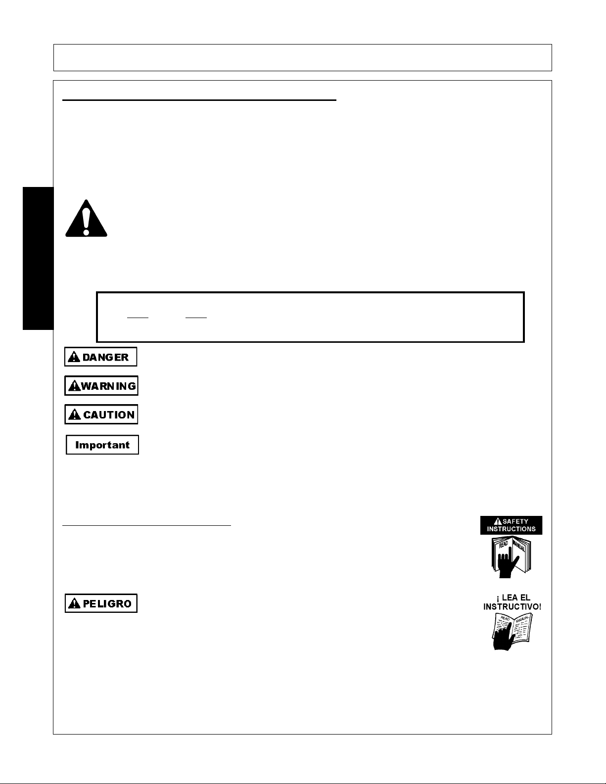
The Safety Alert Symbol combined with a Signal Word, as seen below, is used throughout this
manual and on decals which are attached to the equipment. The Safety Alert Symbol means:
“ATTENTION! BECOME ALERT! YOUR SAFETY IS INVOLVED!” The Symbol and Signal Word
are intended to warn the owner/operator of impending hazards and the degree of possible injury
faced when operating this equipment.
SAFETY
Practice all usual and customary safe working precautions and above all---remember safety is
up to YOU
. Only YOU can prevent serious injury or death from unsafe practices.
Indicates an imminently hazardous situation that, if not avoided, WILL result in DEATH OR
VERY SERIOUS INJURY.
Indicates an imminently hazardous situation that, if not avoided, COULD result in DEATH
OR SERIOUS INJURY.
Indicates an imminently hazardous situation that, if not avoided, MAY result in MINOR
INJURY.
Identifies special instructions or procedures that, if not strictly observed, could result in
damage to, or destruction of the machine, attachments or the environment.
NOTE: Identifies points of particular interest for more efficient and convenient operation or
repair.
(SG-1)
READ, UNDERSTAND, and FOLLOW the following Safety Messages. Serious injury or
death may occur unless care is taken to follow the warnings and instructions stated in the
Safety Messages. Always use good common sense to avoid hazards.
Si no lee ingles, pida ayuda a alguien que si lo lea para que le traduzca las
medidas de seguridad.
(SG-3)
(SG-2)
SHD 03/09 Safety Section 1-2
© 2009 Alamo Group Inc.
Page 9
SAFETY
N
til
d
Operator Safety Instructions and Practices
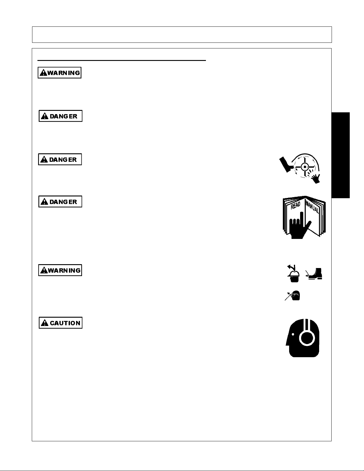
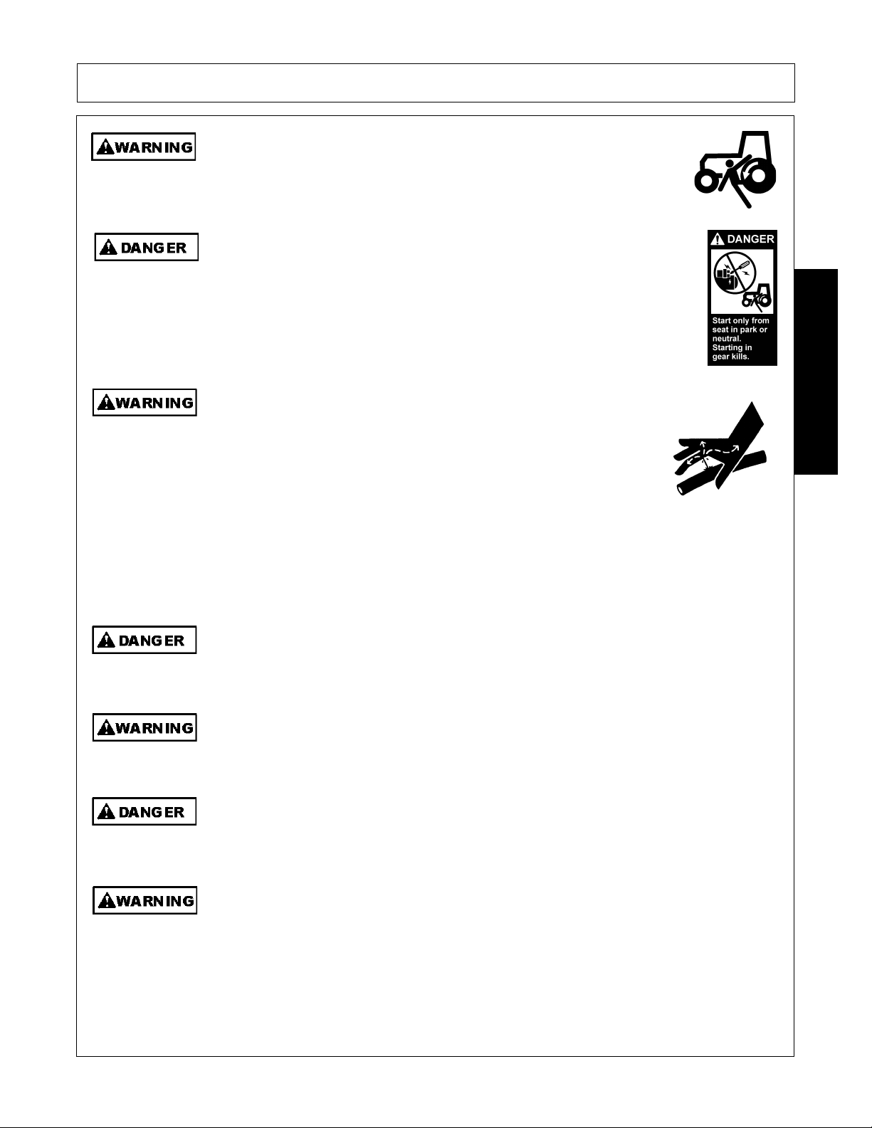
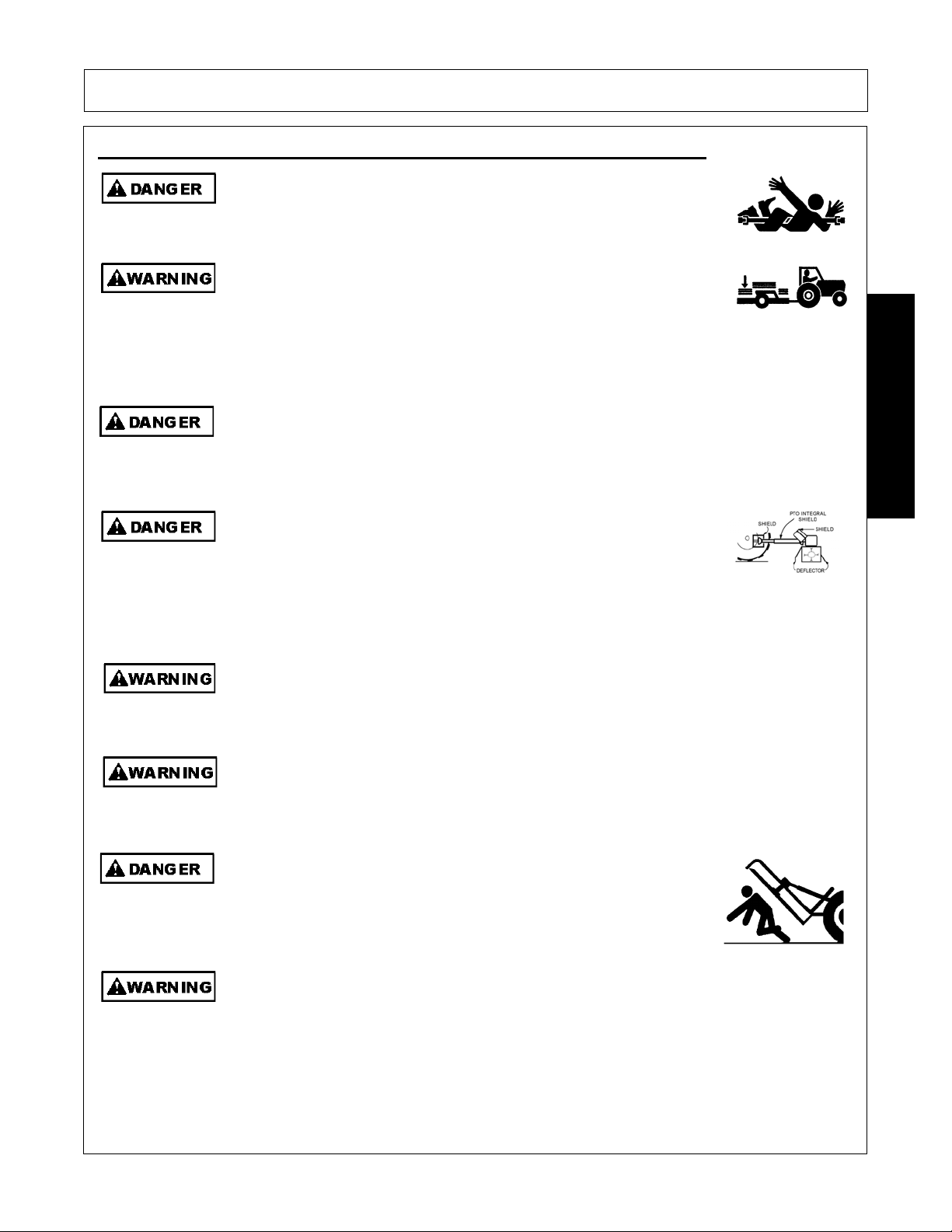
The rotating parts of this machine co ntinue to rot ate ev en after the PT O has been turned of f.
The operator should remain in his seat for 60 seconds after the brake has been set, the
PTO disengaged, the tractor turned off, and all evidence of rotation has ceased.
“Wait a minute...Save a life!”
Never crawl under a raised Implement supported solely by the Tractor 3-Point hitch.
Release of the control lever or mechanical failure will result in the Implement falling and
possible injury or death. Always securely block up the Implement before crawling
underneath to perform repairs and service.
Do not put hands or feet under mower decks. Blade Contact can result
in serious injury or even death. Stay away until all motion has
stopped and the decks are securely blocked up.
(S3PT-19)
(S3PT-10)
SAFETY
(SFL-2)
ever operate the Tractor or Implement un
you have read an
completely understand this Manual, the Tractor Operator’s Manual, and
each of the Safety Messages found in the Manual or on the Tractor and
Implement. Learn how to stop the tractor engine suddenly in an
emergency. Never allow inexperienced or untrained personnel to
operate the Tractor and Implement without supervision. Make sure the
operator has fully read and understood the manuals prior to operation.
(SG-4)
The operator and all support personnel should wear hard hats, safety
shoes, safety glasses, and proper hearing protection at all times for
protection from injury including injury from items that may be thrown by
the equipment.
(SG-16)
PROLONGED EXPOSURE TO LOUD NOISE MAY CAUSE
PERMANENT HEARING LOSS! Tractors with or without an Implement
attached can often be noisy enough to cause permanent hearing loss.
We recommend that you always wear hearing protection if the noise in
the Operator’s position exceeds 80db. Noise over 85db over an
extended period of time will cause severe hearing loss. Noise over 90db
adjacent to the Operator over an extended period of time will cause
permanent or total hearing loss. NOTE: Hearing loss from loud noise
[from tractors, chain saws, radios, a nd other such sources close to the
ear] is cumulative over a lifetime without hope of natural recovery.
(SG-I7)
SHD 03/09 Safety Section 1-3
© 2009 Alamo Group Inc.
Page 10
SAFETY
Al
ith th
Prol
U
tti
d
SAFETY
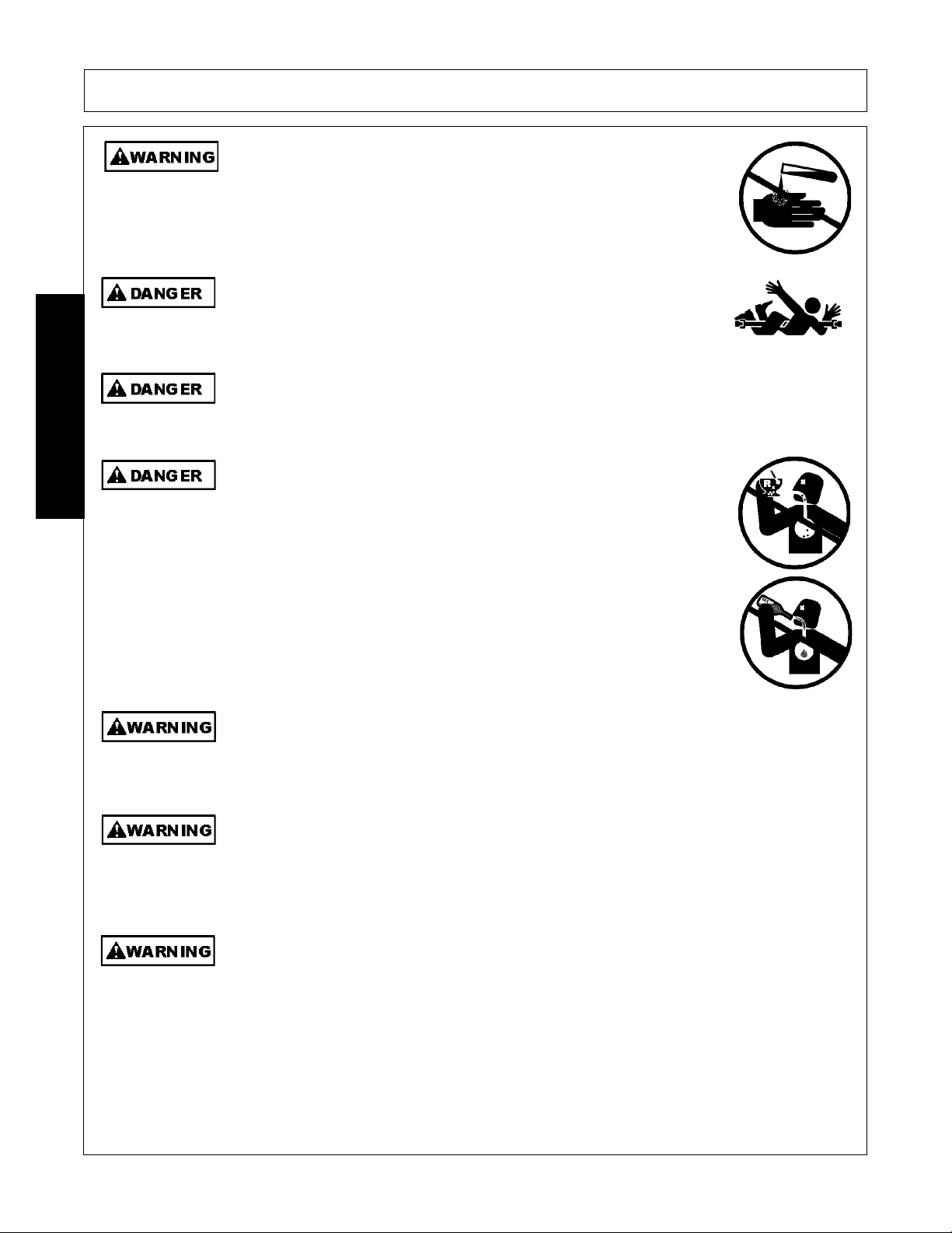
ways read carefully and comply fully w
e manufacturer’s
instructions when handling oil, solvents, cleansers, and any other
chemical agent.
(SG-22)
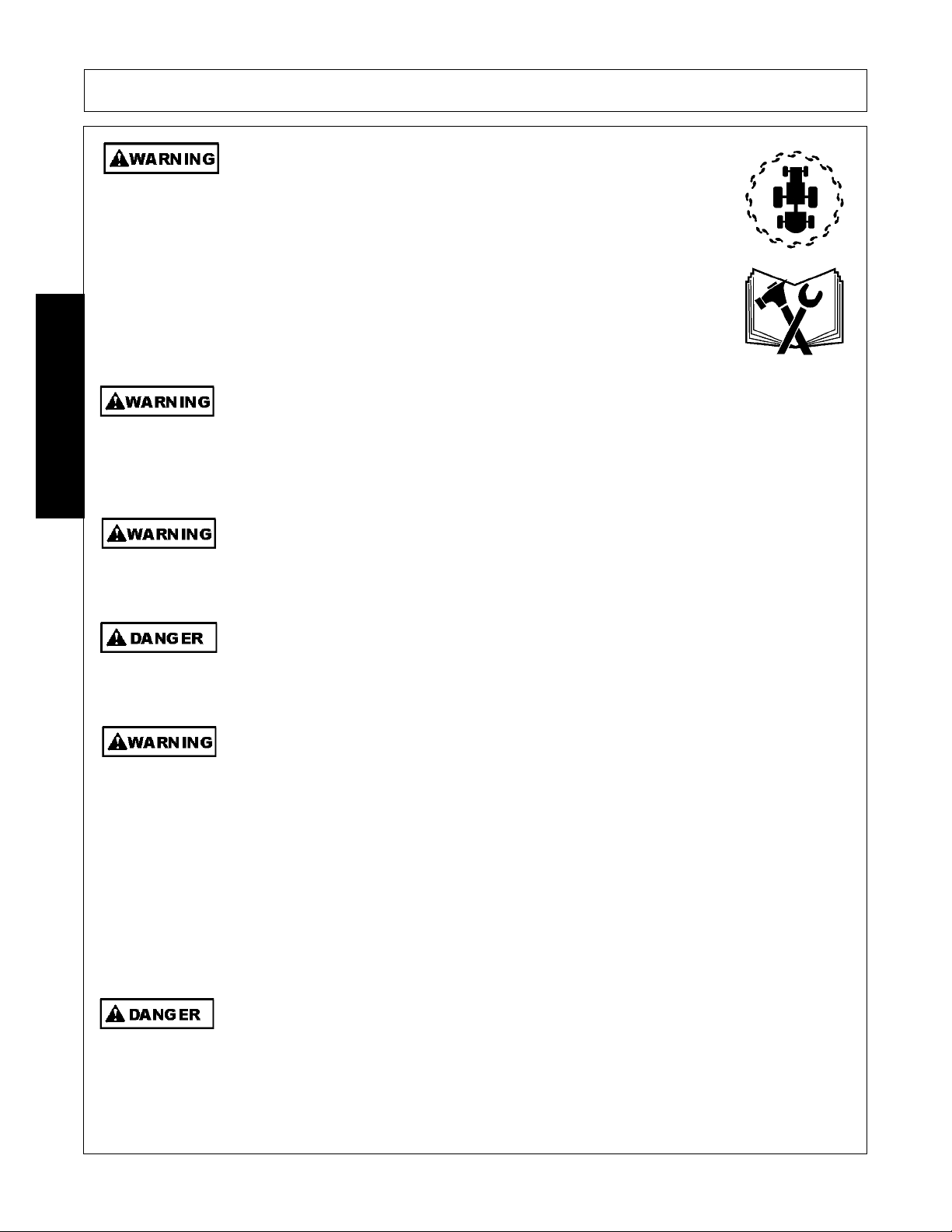
KEEP AWAY FROM ROTATING ELEMENTS to prevent entanglement
and possible serious injury or death.
(SG-24)
Never allow children to play on or around T ractor or Imple ment. Children can slip or fa ll of f
the Equipment and be injured or killed. Children can cause the Implement to shift or fall
crushing themselves or others.
(SG-25)
NEVER use drugs or alcohol immediately before or while operating the
Tractor and Implement. Drugs and alcohol will affect an operator’s
alertness and coordination and therefore affect the operator’s ability to
operate the equipment safely. Before operating the Tractor or
Implement, an operator on prescription or over-the-counter medication
must consult a medical professional regarding any side effects of the
medication that would hinder their ability to operate the Equipment safely.
NEVER knowingly allow anyone to operate this equipment when their
alertness or coordination is impaired. Serious injury or death to the
operator or others could result if the operator is under the influence of
drugs or alcohol.
(SG-27)
onged operation may cause operator boredom and fatigue affecting safe operation.
Take scheduled work breaks to help prevent these potentially impaired operating
conditions. Never operate the Implement and Tractor in a fatigued or bored mental state
which impairs proper and safe operation.
se extreme caution when ge
ng onto the Implement to perform repairs, maintenance an
when removing accumulated material. Only stand on solid flat surfaces to ensure good
footing. Use a ladder or raised stand to access high spots which cannot be reached from
ground level. Slipping and falling can cause serious injury or death.
Avoid contact with hot surfaces including hydraulic oil tanks, pumps, motors, valves and
hose connections. Relieve hydraulic pressure before performing maintenance or repairs.
Use gloves and eye protection when servicing hot components. Contact with a hot surface
or fluid can cause serious injury from burns or scalding.
SHD 03/09 Safety Section 1-4
© 2009 Alamo Group Inc.
(SG-32)
(SG-33)
(SG-34)
Page 11

SAFETY
U
ldi
DO NOT operate this Implement on a Tractor that is not properly maintained. Should a
mechanical or Tractor control failure occur while operating, immediately shut down the
Tractor and perform repairs before resuming operation. Serious injury and possible death
could occur from not maintaining this Implement and Tractor in good operating condition.
(SG-36)
Equipment Operation Safety Instructions and Practices
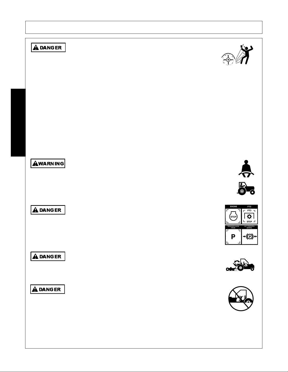
Never leave the Tractor and Implement unattended while the Implement is in the lifted
position. Accidental operation of lifting lever or a hydraulic failure may cause sudden drop
of unit with injury or death by crushing. To properly park the implement when disconnecting
it from the tractor , lower the stan d and put the retaining pin securely in place, or pu t a secure
support under the A-Frame. Lower the implement carefully to th e ground. Do no t put hands
or feet under lifted components.
(S3PT-1)
SAFETY
se extreme care when lowering or unfo
ng the implement’s wings. Make sure no
bystanders are close by or underneath the wings. Allow ample clearance around the
implement when folding or unfolding the wings. Use extreme caution around buildings or
overhead power lines.
(S3PT-05)
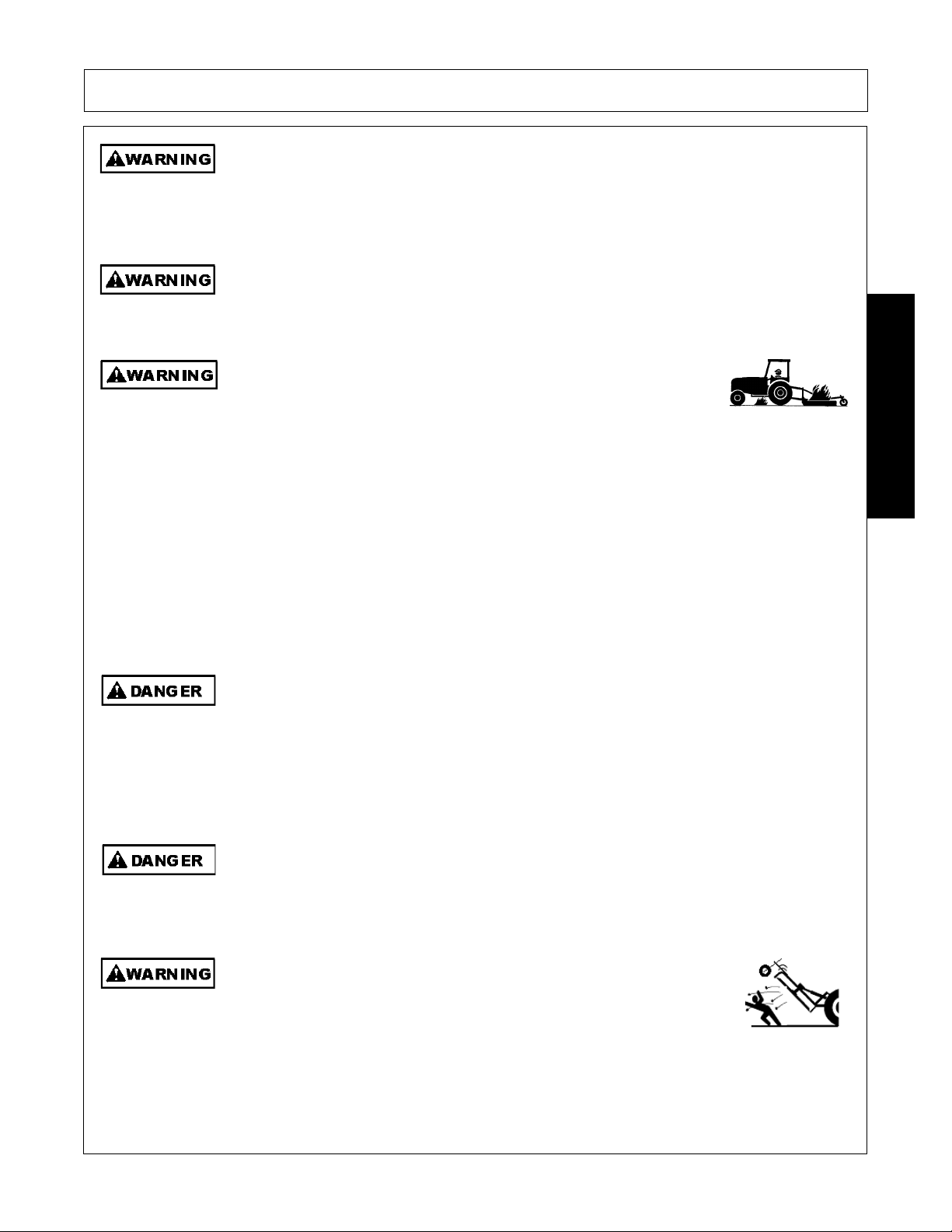
This Implement is wider than the Tractor. Be careful when operating or transporting this
equipment to prevent the Implement from running into or striking sign posts, guar d rails,
concrete abutments or other solid objects. Such an impact could cause the Implement and
Tractor to pivot violently resulting in loss of steering control, serious injury, or even death.
Never allow the Implement to contact obstacles.
(S3PT-12)
There are obvious and hidden potential hazards in the operation of this Mower.
REMEMBER! This machine is often operated in grass and in heavy weeds. The Blades of
this Mower can throw objects if shields are not properly installed and maintained. Serious
injury or even death may occur unless care is taken to insure the safety of the operator, bystanders, or
passersby in the area. Do not operate this machine with anyone in the immediate area. Stop mowing if
anyone is within 100 yards of mower.
(SFL-1)
Do not operate Mower if excessive vibration exists. Shut down PTO and the Tractor
engine. Inspect the Mower to determ ine the source of the vibration. If Mower blad es are
missing or damaged replace them immediately. Do not operate the mower until the
blades have been replaced and the Mower operates smoothly. Operating the Mower with
excessive vibration can result in component failure and broken objects to be thrown
outward at very high velocities. To reduce the possibility of property damage, serious injury,
or even death, never allow the Mower to be operated with blades missing.
(SFL-4)
SHD 03/09 Safety Section 1-5
© 2009 Alamo Group Inc.
Page 12
SAFETY
Flail M
diti
owers are capable under adverse con
ons of throwingobjects
for great distances (100 yards or more) and causing seriousinjury or
death. Follow safety messages carefully.
STOP MOWING IF PASSERSBY ARE WITHIN 100 YARDS UNLESS:
-Front and Rear Deflectors, Chain Guards, or Bands are installed and in good,
workablecondition;
-Mower sections or Wings are running close to and parallel to the ground
withoutexposed Blades;
-Passerby are outside the existing thrown-object zone;-All areas have been thoroughly
inspected and all foreign material such as rocks, cans, glass, and general debris has
been removed.
NOTE: Where there are grass and weeds high enough to hide debris that could
bestruck by the blades, the area should be: inspected and large debris removed, mowed
atan intermediate height, inspected, closely with any remaining debris being removed,
andmowed again at desired final height. (This will also reduce power required to
SAFETY
mow,reduce wear and tear on the Mower drivetrain, spread cut material better,
eliminatestreaking, and make the final cut more uniform.)
(SFL-6)
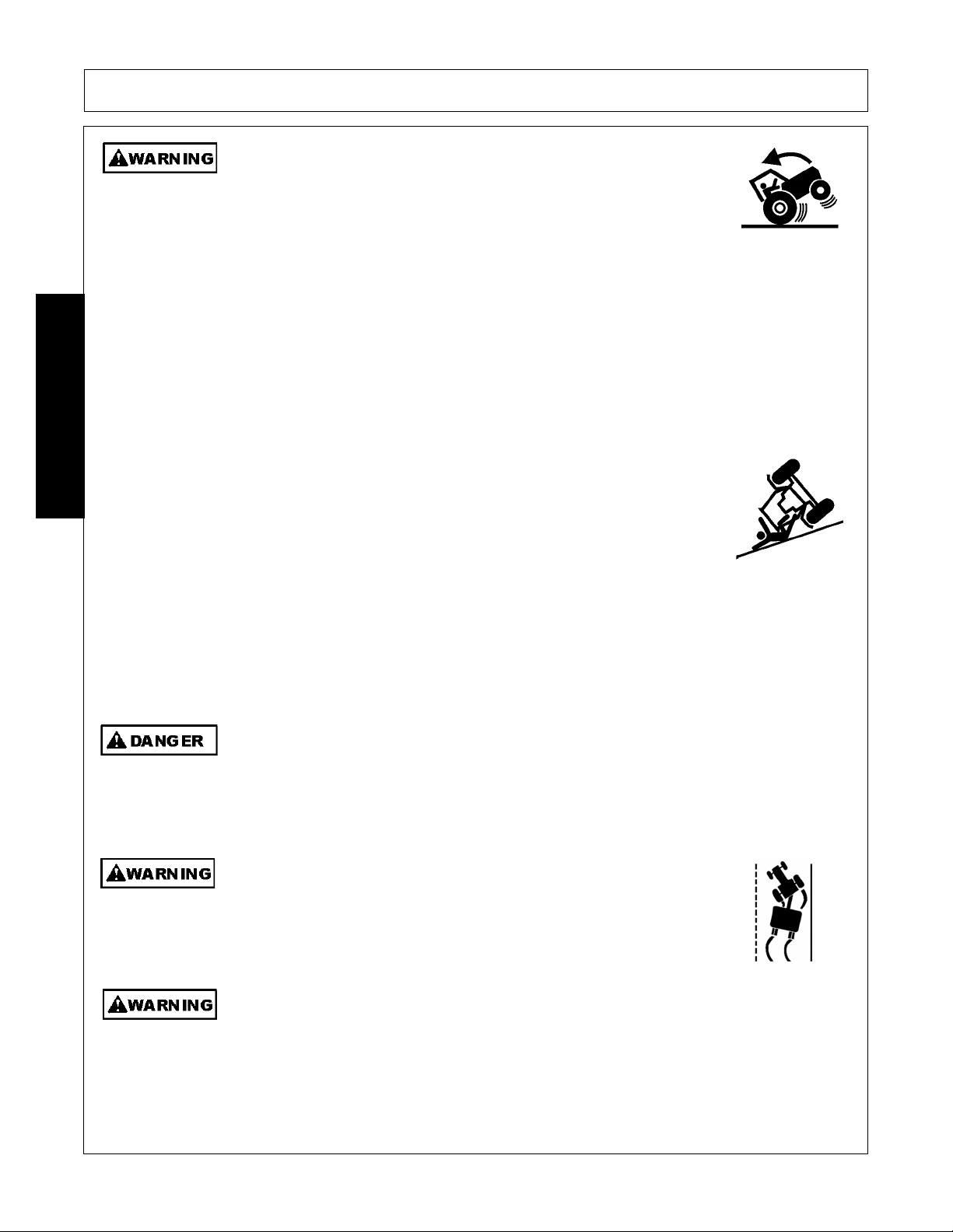
Operate this Equipment only with a Tractor equipped with an approved rollover-protective system (ROPS). Always wear seat belts. Serious injury or
even death could result from falling of f the tractor --particularly during a turnover
when the operator could be pinned under the ROPS.
(SG-7)
BEFORE leaving the tractor seat, always engage the brake and/or set
the tractor transmission in parking gear, disengage the PTO, stop the
engine, remove the key, and wait for all moving parts to stop. Place the
tractor shift lever into a low range or parking gear to prevent the tractor
from rolling. Never dismount a Tractor that is moving or while the engine
is running. Operate the Tractor contr ols from the tractor seat only.
(SG-9)
Never allow children or other persons to ride on the Tractor or Implement.
Falling off can result in serious injury or death.
(SG-10)
Never allow children to operate, ride on, or come close to the Tractor or
Implement. Usually, 16-17 year-old children who are mature and
responsible can operate the implement with adult supervision, if they
have read and understand the Operator’s Manuals, been trained in
proper operation of the tractor and Implement, and are physically large
enough to reach and operate the controls easily.
(SG-11)
SHD 03/09 Safety Section 1-6
© 2009 Alamo Group Inc.
Page 13
SAFETY
I
difficul
k
Do not mount or dismount the Tractor while the tractor is moving. Mount
the Tractor only when the Tractor and all moving parts are completely
stopped.
Start tractor only when properly seated in the Tractor seat. Starting a
tractor in gear can result in injury or death. Read the Tractor operators
manual for proper starting instructions.
Do not operate this Equipment with hydraulic oil or fuel leaking. Oil
and fuel are explosive and their presence could present a hazard. Do
not check for leaks with your hand! High-pressure oil streams from
breaks in the line could penetrate the skin and cause tissue damage
including gangrene. To check for a hose leak, SHUT the unit ENGINE
OFF and remove all hydraulic pressure. Wear oil imp ene trab le glo ves ,
safety glasses and use Cardboard to check for evidence of oil leaks. If
you suspect a leak, REMOVE the HOSE and have it tested at a Dealer.
If oil does penetrate the skin, have the injury treated immediately by a
physician knowledgeable and skilled in this procedure.
(SG-12)
(SG-13)
(SG-15)
SAFETY
Never run the Tractor engine in a closed building or without adequate ventilation. The
exhaust fumes can be hazardous to your health.
Do not exceed the rated PTO speed for the Implement. Excessive PTO speeds can cause
Implement driveline or blade failures resulting in serious injury or death.
Operate the Tractor and/or Implement control s only while properly seated in the Tractor seat
with the seat belt securely fastened around you. Inadvertent movement of the Tractor or
Implement may cause serious injury or death.
n case of mechanical
ty during operation, place the transmission in the par
position, set the parking brake, shut down all power, including the PTO and the engine and
remove the key. Wait until all rotating motion has stopped before dismounting.
SHD 03/09 Safety Section 1-7
(SG-23)
(SG-26)
(SG-29)
(SG-39)
© 2009 Alamo Group Inc.
Page 14
SAFETY
Ext
h
M
M
Do Not operate this equipment in areas where insects such as bees may attack you and/or
cause you to lose control of th e equipment. If you must enter in such areas, use a tractor
with an enclosed Cab and close the windows to prevent insects from entering. If a tractor
cab is not available, wear suitable clothing including head, face, and hand protection to
shield you from the insects. Attacking insects can cause you to lose control of the tractor,
which can result in serious injury or death to yo u o r bystanders. Never dismount a moving
tractor.
Mow only in conditions where you have clear visibility in daylight or with adequate artificial
lighting. Never mow in darkness or foggy conditions where you cannot clearly see at least
100 yards(90 m) in front and to the sides of the tractor and mower. Make sure that you can
clearly see and identify passersby, steep slopes, ditches, drop-offs, overhead obstructions,
power lines, debris and foreign objec ts. If you are unab le to clear ly see thes e type of ite ms
discontinue mowing.
(SG-40)
(SGM-1)
SAFETY
The rotating parts of this machine have been designed and tested for rugged use.
However, the blades could fail upon impact with heavy, solid objects such as metal guard
rails and concrete structures. Such impact could cause the broken objects to be thrown
outward at very high velocities. To reduce the possibility of property damage, serious
injury, or even death, never allow the cutting blades to contact such obstacles.
(SGM-4)
reme care should be taken when operating near loose objects suc
as gravel, rocks, wire, and other debris. Inspect the area before
mowing. Foreign objects should be removed from the site to prevent
machine damage and/or bodily injury or even death. Any objects that
cannot be removed must be clearly mark ed and carefully a vo ide d b y th e
operator. Stop mowing immediately if blades strike a foreign object.
Repair all damage and make certain rotor or blade carrier is balanced
before resuming mowing.
(SGM-05)
any varied objects, such as wire, cable, rope, or chains, can become entangled in the
operating parts of the mower head. These items could then swing outside the housing at
greater velocities than the blades. Such a situation is extremely hazardous and could result
in serious injury or even death. Inspect the cutting area for such objects before mowing.
Remove any like object from the site. Never allow the cutting blades to contact such items.
(SGM-06)
ow at the speed that you can safely operate and control the tractor and mower. The
correct mowing speed depends on terrain condition and grass type, density, and height of
cut. Normal ground speed range is from 2 to 5 mph(3-8 kph). Use slow mowing speeds
when operating on or near steep slopes, ditches, drop-offs, overhead obstructions, power
lines, or when debris and foreign objects are to be avoided.
SHD 03/09 Safety Section 1-8
© 2009 Alamo Group Inc.
(SGM-07)
Page 15
SAFETY
The M
ifi
Avoid mowing in reverse direction when possible. Check to make sure there are no
persons behind the mower and use extreme care when mowing in reverse. Mow only at a
slow ground speed where you can safely operate and control the tractor and mower.
Never mow an area that you have not inspected and removed debris or foreign material.
(SGM-08)
Do not mow with two machines in the same area except with Cab tractors with the windows
closed.
Follow these guidelines to reduce the risk of equipment and grass fires
while operating, servicing, and repairing the Mower and Tractor:
-Equip the Tractor with a fire extinguisher in an accesible location.
-Do Not operate the Mower on a Tractor with an underframe exhaust.
-Do Not smoke or have an open flame near the Mower and Tractor.
-Do Not drive into burning debris or freshly burnt areas.
-Ensure slip clutches are properly adjusted to prevent excessive slippage and plate heating.
(SGM-11)
SAFETY
-Never allow clippings or debris to collect near drivelines, slip clutches, and gearboxes.
Periodically shut down the Tra ctor an d Mo we r and cl ean clip pings an d collected debris fro m
the mower deck.
(SGM-12)
ower is designed for certain mowing applications and is rated to cut up to a spec
size vegetation (see Mower Standard Equipment and Specifications). DO NOT use this
mower to cut vegetation above the Mower’s rated capacity or to cut any type of nonvegetative material. Only operate this Mower on a properly sized and equipped Tractor.
Operating this Mower in an application for which it is not designed and/or operating the
Mower with the wrong size Tractor can cause Mower component damage and equipment
failure resulting in possible serious injury or death.
(SGM-14)
Do Not attempt to raise or lower the implement wing unless the Implement tongue is
securely attached to the Tractor drawbar. The Implement could tip over and cause
equipment damage and possible ser ious injury or death. Raise or Lo wer the mower wing
only while seated in the Tractor operator’s seat with the seat belt securely fastened.
Do not let the Blades turn when the Mower Deck is raised for any
reason, including clearance or for turning. Raising the Mower deck
exposes the Cutting Blades which creates a potentially serious hazard
and could cause serious injury or even death from objects thrown from
the Blades.
(SRM-07)
c
(SRM-2)
SHD 03/09 Safety Section 1-9
© 2009 Alamo Group Inc.
Page 16

SAFETY
Wh
PTO, it is i
DO NOT allow any person under a folded wing unless wing is securely
locked up or supported. DO NOT approach the Implement unless the
Tractor is turned off and all motion has ceased. Never work under the
frame work, or any lifted component unless the implement is securely
supported or blocked up. A sudden or inadvertent fall by any of these
components could cause serious injury or even death.
Connecting or Disconnecting Implement Safety Instructions and Practices
DO NOT use a PTO adapter to attach a non-matching Implement driveline to a Tractor
PTO. Use of an adapter can double the operating speed of the Implement resulting in
excessive vibration, thrown objects, and blade and implement failure. Adapter use will also
change the working length of the driveline exposing unshielded driveline areas. Serious
bodily injury and/or equipment failure can result from using a PTO adapter. Consult an
SAFETY
authorized dealer for assistance if the Implement driveline does not match the Tractor PTO.
(S3PT-14)
Always shut the Tractor completely down, place the transmission in park, and set the
parking brake before you or anyone else attempts to connect or disconnect the Implement
and Tractor hitches.
(S3PT-15)
(STI-03)
Never operate the Tractor and Mower if the Implement input driveline is directly connected
to the Tractor transmission. Tractor braking distances can be substantially increased by
the momentum of the rotating Mower blades driving the Tractor transmission even though
the Tractor clutch has been dise nga ge d. Install an over running clutch between the Tractor
PTO and the Mower driveline to prevent this potentially dangerous situation.
en attaching the Implement input driveline to the Tractor
connecting yoke spring activated locking collar slides freely and the locking balls are seated
securely in the groove on the Tractor PTO shaft. Push and pull the driveline back and forth
several times to ensure it is securely attached. A driveline not attached correctly to the
Tractor PTO shaft could come loose and result in personal injury and damage to the
Implement.
Before operating the Implement, check to make sure the Implement input driveline will not
bottom out or become disengaged. Bottoming out occurs when the inner shaft penetrates
the outer housing until the assembly beco mes solid-it c an shorten no m ore. Bottomin g out
can cause serious damage to the Tractor PTO by pushing the PTO into the Tractor and
through the support bearings or downward onto the PTO shaft, breaking it off. A broken
driveline can cause personal injury.
(S3PT-17)
(S3PT-18)
(S3PT-16)
mportant that the
SHD 03/09 Safety Section 1-10
© 2009 Alamo Group Inc.
Page 17
SAFETY
r
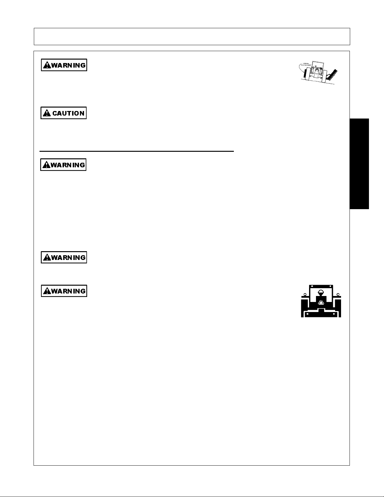
Each Rear Wheel must have a minimum of 1,000 pounds cont act with the
surface to prevent lateral instability and possible tip-over which could
result in serious bodily injury or even death. Widen the wheel tread and
add weights if needed. Refer to the mountin g instructio ns or ca ll customer
service if you need assistance with counterweight procedure.
On a fully-assembled unit, do not remove the Wing Retaining Strap until hoses are attached
to the tractor and the Wing Cylinders are filled with oil. Lower the Wings slowly and
carefully. Keep bystanders away during operations.
Transporting Safety Instructions and Practices
Be particularly careful when transporting the Implement with the Tractor. Turn curves or go
up hills only at a low speed and using a gradual steering angle. Rear mounted implements
move the center of gravity to the rear and remove weight from the front wheels. Make
certain, by adding front ballast, that at least 20% of the tractor’s weight is on the front wheels
to prevent rearing up, loss of steering control or Tractor tip-over. Slow down on rough o
uneven surfaces to prevent lo ss of steering control which could result in property damage
or possible injury. Do not transport unless 3-Point lift lever is fully raised and in the latched
transport position. Dropping implement in transport can cause serious damage to the
tractor and/or Implement and possibly cause the operator or others to be injured or killed.
(S3PT-02)
(SFL-3)
(STI-05)
SAFETY
Allow sufficient clearance for the Implement to swing outward while turning. Implements
carried behind the Tractor will swing outside the tire path when making turns. Contacting a
solid object while turning will cause equipment damage and possible injury.
Make certain that the “Slow Moving Vehicle” (SMV) sign is installed in
such a way as to be clea rly visible and legible. When transporti ng the
Equipment use the Tractor flashing warning lights and follow all local
traffic regulations.
(SG-6)
(S3PT-20)
SHD 03/09 Safety Section 1-11
© 2009 Alamo Group Inc.
Page 18
SAFETY
Only t
Transport only at speeds where you can maintain control of the
equipment. Serious accidents and injuries can result from operating this
equipment at high speeds. Understand the Tractor and Implement and how it handles
before transporting on streets and highways. Make sure the Tractor steering and brakes
are in good condition and operate properly.
Before transporting the Tractor and Implement, determine the proper transport speeds for
you and the equipment. Make sure you abide by the following rules:
Test the tractor at a slow speed and increase the speed slowly. Apply the Brakes smoothly
to determine the stopping characteristics of the Tractor and Implement. As you increase
the speed of the Tractor the stopping distance increases. Determine the maximum
transport speed not to exceed 20 mph (30 kph) for transporting this equipment.
Test the equipment at a slow speed in turns. Increase the speed through the turn only after
you determine that the equipment can be operated at a higher speed. Use extreme care
SAFETY
and reduce your speed when turning sharply to prevent the tractor and implement from
turning over. Determine the maximum turning speed for you and this equipment before
operating on roads or uneven ground.
Only transport the Tractor and Implement at the speeds which allow you to properly control
the equipment.
Be aware of the operating conditions. Do not operate the Tractor with weak or faulty brakes
or worn tires. When operating down a hill or on wet or rain slick roads, the braking distance
increases: use extreme care and reduce your speed. When operating in traffic always use
the Tractor’s flashing warning lights and r educe your speed. Be aware of traf fic around you
and watch out for the other guy.
When the Wings are folded for transport, the center of gravity is raised and the possibility of
overturn is increased. Drive slowly and use extreme caution when turning on hillsides.
Overturning the Implement could cause the Implement to overturn the Tractor and vice
versa resulting in serious injury or even death. Never fold wings on a hillside...the
Implement may overturn.
ow the Implement behind a properly sized and equipped Tractor
which exceeds the weight of the Implement by at least 20%. DO NOT
tow the Implement behind a truc k or othe r type of ve hicle. N eve r tow the
Implement and another Implement connected in tandem. Never tow the
Implement at speeds over 20 MPH.
Secure the Implement for transport before traveling on public roads. For pull-type
Implements, secure the center axle using cylind er stops or transport pin and properly att ach
a safety chain between the Implement and Tractor. Secure wings in upright position on
folding Implements using wing transport locks.
(SG-19)
(STI-02)
(STI-06)
(STI-7)
SHD 03/09 Safety Section 1-12
© 2009 Alamo Group Inc.
Page 19
SAFETY
Maintenance and Service Safety Instructions and Practices
Make sure the PTO shield, integral driveline shields, and input shields
are is installed when using PTO-driven equipment. Always replace any
shield if it is damaged or missing.
Relieve hydraulic pressure prior to doing any maintenance or repair work
on the Implement. Place the Implement on the ground or securely
blocked up, disengage the PTO, and turn off the tractor engine. Push
and pull the Remote Cylinder lever in and out several times prior to
starting any maintenance or repair work.
Always disconnect the main PTO Driveline from the Tractor before performing service on
the Implement. Never work on the Implement with the tractor PT O dr iveline connecte d and
running. Rotating Parts, Blades or Drivelines could turn without warning and cause
immediate entanglement, injury or death.
All Safety Shields, Guards and Safety devices including (but not limited
to) - the Deflectors, Steel Guards, Gearbox Shields, PTO integral
shields , and Retractable Door Shields should be used and maintained
in good working condition. All safety devices should be inspected carefully at least daily
for missing or broken components. Missing, broken, or worn items must be replaced at
once to reduce the possibility of injury or death from thrown objects, entanglement, or
blade contact.
(SFL-5)
(S3PT-8)
(S3PT-09)
(S3PT-11)
SAFETY
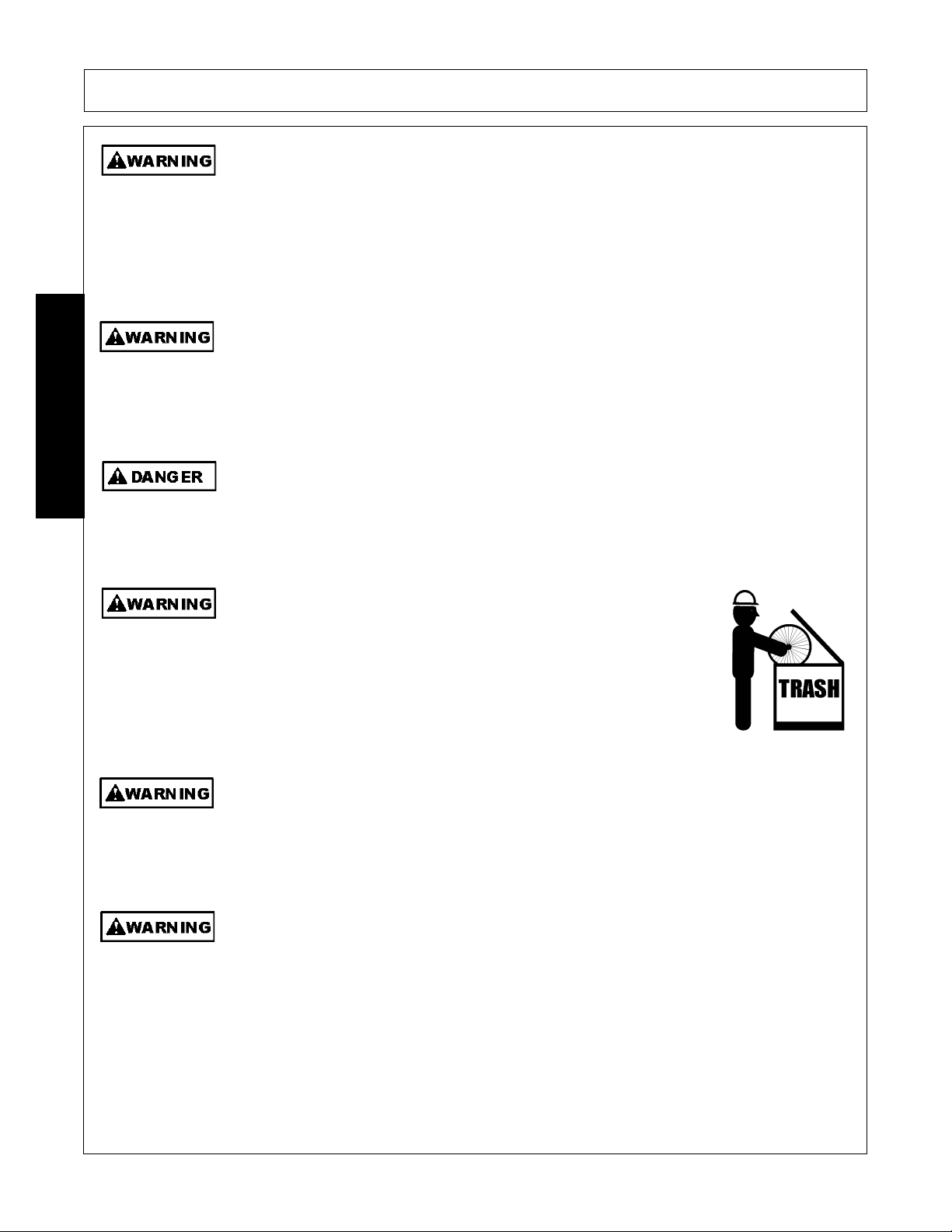
Always maintain the safety signs in good readable condition. If th e safety signs are missing,
damaged, or unreadable, obtain and install replacement safety signs immediately.
(SG-5)
Do not modify or alter this Implement. Do not permit anyone to modify or alter this
Implement, any of its components or any Implement function.
(SG-8)
Never work under the Implement, the framework, or any lifted
component unless the Implement is securely supported or blocked up
to prevent sudden or inadvertent falling which could cause serious
injury or even death.
(SG-14)
Never attempt to lubricate, adjust, or remove material from the Implement while it is in
motion or while tractor engine is running.
(SG-20)
SHD 03/09 Safety Section 1-13
© 2009 Alamo Group Inc.
Page 20
SAFETY
U
dli
SAFETY
Periodically inspect all moving parts for wear and replace when
necessary with authorized service parts. Look for loose fasteners, worn
or broken parts, and leaky or loose fittings. Make sure all pins have
cotter pins and washers. Serious injury may occur from not maintaining
this machine in good working order.
Perform service, repairs and lubrication according to the maintenance section. Ensure the
unit is properly lubricated as specified in the lubrication schedule and all bolts and nuts are
properly torqued. Failure to properly se rvice, repair and maintain this Implement in good
operating condition could cause component failure and possible serious injury or even
death.
(SG-35)
(SG-21)
se caution and wear protective gloves when han
ng sharp objects such as blades,
knives, and other cutting edges. Be alert to worn component surfaces which have sharp
edges. Sharp surfaces can inflict severe laceration injuries if proper hand protection is not
worn.
(SG-37)
Replace bent or broken blades with new blades. NEVER ATTEMPT TO STRAIGHTEN,
WELD, OR WELD HARDFACING ON BLADES SINCE THIS WILL LIKELY CRACK OR
OTHERWISE DAMAGE THE BLADE WITH SUBSEQUENT FAILURE AND POSSIBLE
SERIOUS INJURY FROM THROWN BLADES.
(SGM-10)
DO NOT weld or repair rotating mower components. Welds and other repairs may cause
severe vibration and/or component failure resulting in part being thrown from the mower
causing serious bodily injury. See your Authorized Dealer for proper repairs.
(SGM-13)
PARTS INFORMATION
Alamo Industrial mowers use balanced and matched system components for blade carriers, blades,
cuttershafts, knives, knife hangers, rollers, drivetrain components, and bearings. These parts are made and
tested to Alamo Industrial specifications. Non-genuine "will fit" parts do not consistently meet these
specifications. The use of “will fit” parts may reduce mower performance, void mower warranties, and present
a safety hazard. Use genuine Alamo Industrial mower parts for economy and safety.
(SPRM-1)
SEE YOUR ALAMO DEALER
Always disconnect the main PTO Driveline from the Tractor before performing service on
the Implement. Never work on the Implement with the tractor PT O dr iveline connecte d and
running. Rotating Parts, Blades or Drivelines could turn without wa rning and cause immediate entanglement, injury or death.
SHD 03/09 Safety Section 1-14
(S3PT-11)
© 2009 Alamo Group Inc.
Page 21

SAFETY
Always disconnect the wire leads from the mower valve solenoid
before performing service on the Tractor or Mower. Use caution when
working on the Tractor or Mower. Tractor engine must be stopped
before working on Mower or Tractor. The Mower Blades could
inadvertently be turned on without warning and cause immediate
dismemberment, injury or death.
Concluding Safety Instructions and Practices
In addition to the design and configuration of this Implement, including Safety Signs and Safety Equipment,
hazard control and accident prevention are dependent upon the awareness, concern, prudence, and proper
training of personnel involved in the operation, transport, maintenance, and storage of the machine. Refer
also to Safety Messages and operation instruction in each of the appropriate sections of the Tractor and
Equipment Manuals. Pay close attention to the Safety Signs affixed to the Tractor and Equipment.
(SBM-12)
(SG-18)
SAFETY
SHD 03/09 Safety Section 1-15
© 2009 Alamo Group Inc.
Page 22
SAFETY
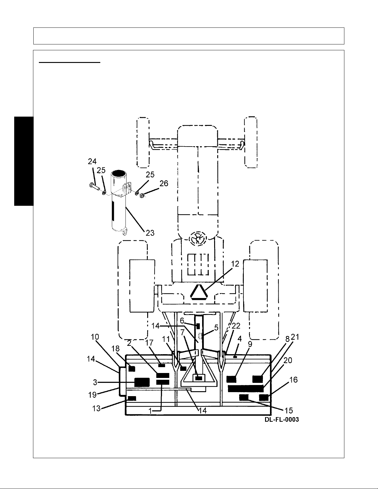
Decal Location
NOTE: Alamo Industrial supplies safety decals on this product to promote safe operation. Damage to the
decals may occur while in shipping, use, or reconditioning. Alamo Industrial cares about the safety of its
customers, operators, and bystanders, and will replace the safety decals on this product in the field, free of
charge (Some shipping and handling charges may apply). Contact your Alamo Industrial dealer to order
replacement decals.
SAFETY
SHD 03/09 Safety Section 1-16
© 2009 Alamo Group Inc.
Page 23

SAFETY
ITEM PART NO. QTY LEVEL DESCRIPTION
1. 00725746 1 PELIGRO Translate Safety Material
2. 00773723 1 PELIGRO Translate Driveline Instructions
3. 002369 1 DANGER Multi-Hazard
4. 002425 1 DANGER Front Shield
5. 00756004 ref DANGER Shield Missing
6. 00756005 ref DANGER Rotating Driveline
7. 00756494 1 DANGER Driveline Safety
8. 02967668 1 DANGER Cutting Blades
9. 00725739 1 WARNING Repair Shields
10. 00758194 1 WARNING Pinch Points (V-Belt)
11. D103 1 WARNING 540 PTO Required
12. 03200347 ref REFLECT SMV Emblem
13. 000108 1 INSTRUCT Operating Instructions
14. 00678 3 INSTRUCT Grease Fitting Inside
15. 001830 1 INSTRUCT Lubrication Chart
16. 002023 1 INSTRUCT Cutting Height Instructions
17. 00763977 1 INSTRUCT Notice to Owners
18. 02925100 1 INSTRUCT Genuine Parts
19. 001650 1 LOGO Alamo Logo
20. 001651 1 LOGO Alamo by Mott
21. 02960766 1 LOGO Alamo Logo
22. nfs 1 SERIALPLT Serial Plate
23. 02977417 1 INSTRUCT Operators Manual Inside (Decal)
24. 02977385 1
25. 803211C 1
26. 10058000 4
27. 00017000 4
28. 00024100 4
Canister, Operator’s Manual
Operator’s Manual
Bolt
Lockwasher
Flatwasher
SAFETY
SHD 03/09 Safety Section 1-17
© 2009 Alamo Group Inc.
Page 24
Decal Description
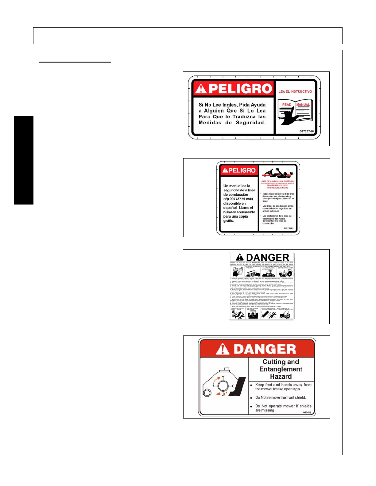
Peligro Translation, If you do not know how to read
English, please find someone who knows how to
read English.
P/N 00725746
PELIGRO! Spanish Translation for Driveline Safety
SAFETY
SAFETY
P/N 00773723
Danger! Mult-Hazard Warning. Failing to follow
these Safety Messages and Operating Instructions
can cause serious bodily injury or even death to
operator and others in the area.
P/N 002369
DANGER! Keep Away! If front deflector shield is
removed from flail housing, serious injury to or
amputation of hands, feet, or limbs may occur from
blades contact. Always make sure that all shields
are in place at all times.
P/N 002425
SHD 03/09 Safety Section 1-18
© 2009 Alamo Group Inc.
Page 25
SAFETY
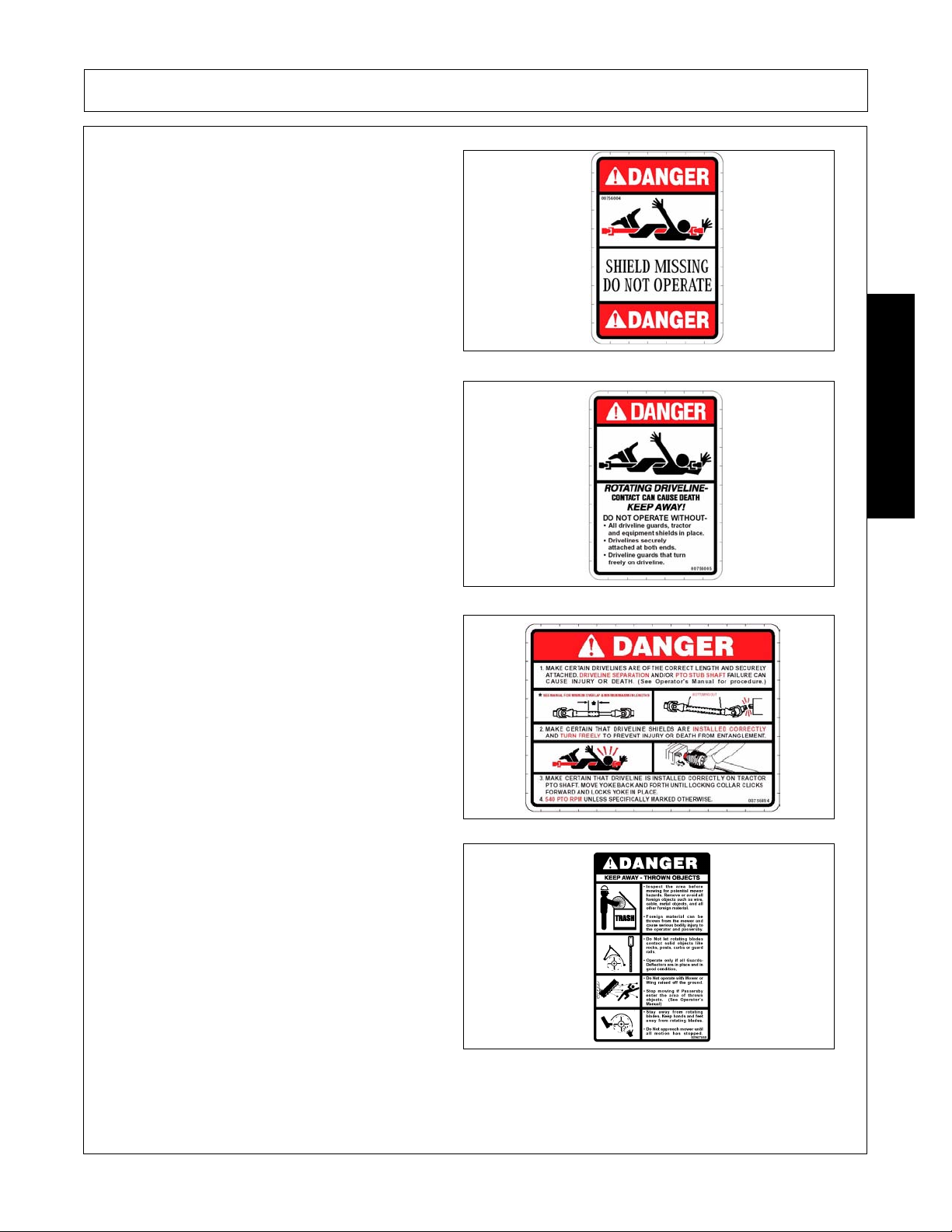
DANGER! Guard Missing, Do Not Operate. If you
see this decal, Do Not Operate the mower until the
shield has been replaced.
P/N 00756004
DANGER! Rotating Driveline Keep Away, Contact
can cause death.
P/N 00756005
DANGER! Make certain that drivelines are correct
length and are securely attached.
SAFETY
P/N 00756494
DANGER! - Keep Away - Thrown Objects. Inspect
area before mowing. Do not let rotating blades
contact solid objects. Operate only if all Guards Deflectors are in place. Do not operate with Mower
or Wing raised off the ground. Stop mowing if
Passerby enter the area. Stay away from rotating
blades. Keep hands and feet away from rotating
blades. Do not approach mower until all movement
has stopped.
P/N 02967668
SHD 03/09 Safety Section 1-19
© 2009 Alamo Group Inc.
Page 26

WARNING! Failure to use and maintain shields
and deflectors in good condition may lead to injury
or death from entanglement with rotating parts.
being hit by objects thrown with great force by
blades, or by blade contact.
P/N 00725739
WARNING! Do not operate with Belt Shield
removed. Finger(s) may be pinched off if get caught
between V-Belt and Pulley.
SAFETY
SAFETY
P/N 00758194
WARNING! Avoid Bodily Injury, Use 540RPM PTO
Speed Only.
P/N D103
Slow Moving Vehicle Decal. Keep SMV reflector
clean and visible. DO NOT transport or operate
without the SMV.
P/N 03200347
SHD 03/09 Safety Section 1-20
© 2009 Alamo Group Inc.
Page 27
SAFETY
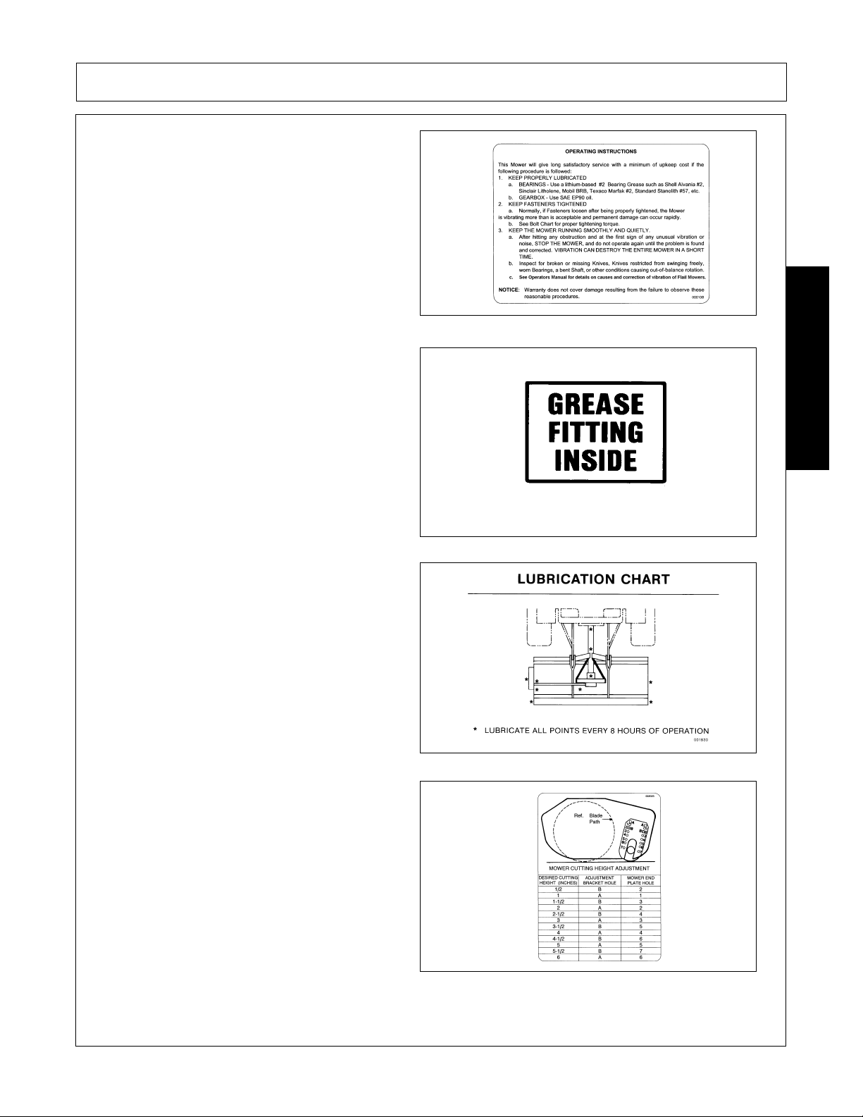
Instructions to properly lubricate and check mower
for potential problems prior to operation.
P/N 000108
Information that Grease Fitting is present and must
apply grease.
P/N 000678
INFORMATION - 8 Hour Lubrication Chart
SAFETY
P/N 001830
Cutting Height Adjustment Chart
P/N 002023
SHD 03/09 Safety Section 1-21
© 2009 Alamo Group Inc.
Page 28

Operator's Manual (with repair parts) and warranty
was attached to this implement during final
inspection.
P/N 00763977
IMPORTANT - Use only Genuine Alamo Industr ial
replacement parts.
SAFETY
SAFETY
P/N 02925100
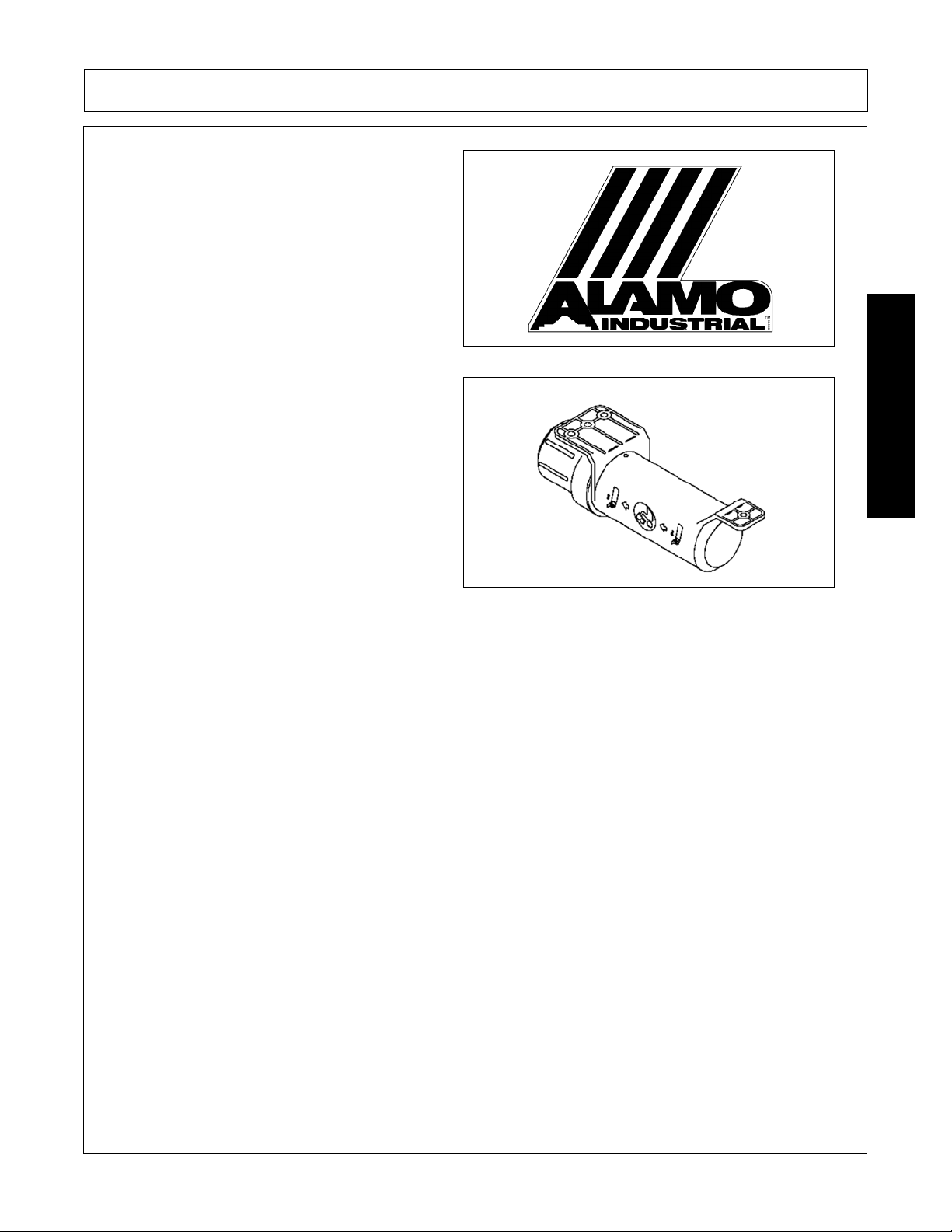
ALAMO NAME LOGO.
P/N 001650
ALAMO INDUSTRIAL LOGO
P/N 001651
SHD 03/09 Safety Section 1-22
© 2009 Alamo Group Inc.
Page 29
NAME LOGO - Alamo Industrial
SAFETY
P/N 02960766
Read Operator’s Manual! The operator’s manual is
located inside this canister. If the manual is
missing order one from your dealer.
P/N 00776031
SAFETY
SHD 03/09 Safety Section 1-23
© 2009 Alamo Group Inc.
Page 30

SAFETY
Federal Laws and Regulations
This section is intended to explain in broad terms th e concept and effect of federal laws and regulations
concerning employer and employee equipment operators. This section is not intended as a legal
interpretation of the law and should not be considered as such.
Employer-Employee Operator Regulations
U.S. Public Law 91-596 (The Williams-Steiger Occupational and Health Act of 1970) OSHA
This Act Seeks:
“...to assure so far as possible every working man and woman in the nation safe and healthful working
conditions and to preserve our human resources...”
DUTIES
Sec. 5 (a) Each employer(1) shall furnish to each of his employees employment and a place of employment which are free from
recognized hazards that are causing or are likely to cause death or serious physical harm to his employees;
SAFETY
Employer Responsibilities:
(2) shall comply with occupational safety and health standards promulgated under this Act.
(b) Each employee shall comply with occupational safety and health standards and all rules, regulations and
orders issued pursuant to this Act which are applicable to his own actions and conduct.
OSHA Regulations
OSHA regulations state in part: “At the time of initial assignment and at least annually thereafter, the employer
shall instruct every employee in the safe operation and servicing of all equipment with which the employee is,
or will be involved.”
To ensure employee safety during Tractor and Implement operation, it is the employer’s responsibility to:
1. Train the employee in the proper and safe operation of the Tractor and Implement.
2. Require that the employee read and fully understand the Tractor and Implement Operator’s manual.
3. Permit only qualified and properly trained employees to operate the Tractor and Implement.
4. Maintain the Tractor and Implement in a safe operational condition and maintain all shields and guards on the
equipment.
5. Ensure the Tractor is equipped with a functional ROPS and seat belt and require that the employee ope rator
securely fasten the safety belt and operate with the ROPS in the raised position at all times.
6. Forbid the employee operator to carry additional riders on the Tractor or Implement.
7. Provide the required tools to maintain the Tractor and Implement in a good safe working condition and provide the
necessary support devices to secure the equipment safely while performing repairs and service.
8. Require that the employee operator stop operation if bystanders or passersby come within 25 feet.
Child Labor Under 16 Years of Age
Some regulations specify that no one under the age of 16 may operate power machinery. It is your
responsibility to know what these regulations are in your own area or situation. (Refer to U.S. Dept. of
Labor, Employment Standard Administration, Wage & Home Division, Child Labor Bulletin #102.)
SHD 03/09 Safety Section 1-24
© 2009 Alamo Group Inc.
Page 31

Page 32

Page 33

Page 34

Page 35

Page 36

Page 37

Page 38

Page 39

Page 40

Page 41

Page 42

Page 43

Page 44

Page 45

Page 46

Page 47

Page 48

Page 49

Page 50

Page 51

Page 52

Page 53

Page 54

Page 55

Page 56

Page 57

Page 58

Page 59

Page 60

Page 61

Page 62

Page 63

Page 64

Page 65

Page 66

Page 67

Page 68

Page 69

Page 70

Page 71

Page 72

Page 73

Page 74

Page 75

INTRODUCTION SECTION
© 2009 Alamo Group Inc.
Introduction Section 2-1
Page 76

INTRODUCTION
This Flail Mower is designed with care and built with quality materials by skilled workers. Proper assembly,
maintenance, and operating practices, as described in this manual, will help the owner/operator get years of
satisfactory service from the machine.
The purpose of this manual is to familiarize, instruct, and train. The Assembly Section instructs the owner/
operator in the correct assembly of the Mower using standard and optional equipment. The Parts Manual is
designed to familiarize the owner/operator with replaceable parts on the Mower and is provided also. This
section provides exploded assembly drawings of each mower component illustrating each piece and the
corresponding part number.
Careful use and timely service saves extensive repairs and costly downtime losses. The Operation and
Maintenance Sections of the manual train the owner/operator how to work the Mower correctly and attend to
appropriate maintenance. The Trouble Shooting Guide helps diagnose difficulties with mower and offers
solution to the problems.
Safety is of primary importance to the owner/opera tor an d to the ma nufa ctur er. The first section of this manual
includes a list of Safety Messages, that, if followed, will help protect the operator and bystanders from injury or
death. Many of the Safety Messages will be repeated throughout the manual. The owner/operator/dealer
INTRODUCTION
should know these Safety Messages before as sembly and be aware of the hazards of operating this mo wer
during assembly, use, and maintenance. The Safety Alert Symbol combined with a Signal Word, as seen
below, is intended to warn the owner/operator of impe nding hazards and the degre e of possible injury faced
when operating this machine.
Indicates an imminently hazardous situation that, if not avoided, WILL result in DEATH OR
VERY SERIOUS INJURY.
Indicates an imminently hazardous situation that, if not avoided, COULD result in DEATH
OR SERIOUS INJURY.
Indicates an imminently hazardous situation that, if not avoided, MAY result in MINOR
INJURY.
Identifies special instructions or procedures that, if not strictly observed, could result in
damage to, or destruction of the machine, atta ch me n ts or the en vir on m en t.
SHD 03/09 Introduction Section 2-2
© 2009 Alamo Group Inc.
Page 77

INTRODUCTION
INTRODUCTION
The Super Heavy Duty Flail is made from the proven, time-tested design of Alamo Industrial, offering you a
manicured look with substantial safety. It is the ideal machine not only for roadside use, but also for parks,
playgrounds, school grounds, and even golf courses.
Strong top decks make with 10-gauge steel and end plates that are 1/2” thick for the inboard and 5/16” thick
steel for the outboard.
• Convenient Mount---3pt. hitch that mounts to 36 HP or greater tractors.
• Sharp appearance---Leaves a manicured cut appearance.
• Variety of lengths to suit your needs---62”, 74”, 88” and 96”
• Knife Options---An array of cutting knife options allows you to tailor the finished appearance to meet your
needs.
Knife V ariety - An array of cutting knif e options allows you to t ailor the finishe d appearan ce to meet your needs.
Cutting Capacity: 1” diameter grass and weeds.
Cutting Widths: SHD 62”, 74”, 88” and 96”
Warranty: One year parts and labor . Non -governmen t al use rs subject to a modified policy. Only genuine Alamo
Industrial OEM parts may be used for warranty replacement.
SHD 03/09 Introduction Section 2-3
© 2009 Alamo Group Inc.
Page 78

INTRODUCTION
Attention Owner/Operator
BEFORE OPERATING THIS MACHINE:
1. Carefully read the Operator’s Manual, completely understand the Safety Messages and instructions, and
know how to operate correctly both the tractor and implement.
2. Fill out the Warranty Card in full. Be sure to answer all questions, including the Serial Number of the
implement. Mail within 30 days of delivery date of this implement.
NOTE: Warranties are honored only if completed “Owner Registration and Warranty” forms are received by
Alamo Industrial within thirty days of delivery of the implement.
3. Record the Model and Serial Numbers on the W arranty p age at the front of the Operator’s Manual. Keep this
as part of the permanent maintenance file for the implement.
INTRODUCTION
SHD 03/09 Introduction Section 2-4
© 2009 Alamo Group Inc.
Page 79

ASSEMBLY SECTION
© 2009 Alamo Group Inc.
Assembly Section 3-1
Page 80

ASSEMBLY
GENERAL
To help you assemble your new SHD FLAIL to your tractor, we provide you with drawings, instructions, and
information, if necessary, you may get more information or clarification from our Technical Services
Department over the phone.
IMPORTANT
Reference to the left or right side of the SHD FLAIL is determined while facing the front of the tractor from the
drivers seat.
Assemble the SHD FLAIL, step by step, as illustrated on the pages of this section. Small parts (bolts, nuts,
etc.>) required are packed in numbered plastic bags which correspond to assembly procedures and
illustrations in the manual.
The part quantities listed for an illustration pertain only to that phase of assembly. The quantity given
corresponds to the number of parts needed.
Large parts are not always listed next to an illustration, but they are usually easy to identify.
Whenever reference is made to parts listed for an illustration or elsewhere in this manual, the following
ASSEMBLY
abbreviations are used:
BOLT-hex head bolt
LW-lock washer
PW-plain washer
When installing fasteners, PW and L W (generally installed in that order) are usually on the side of the fixture or
part being fastened that the hex lock nut is on. When only BOLT, LW and/or PW are required, they are
generally installed in that order. Some parts do not require a PW or LW. Refer to illustrations for exceptions.
Fasteners should be installed so they cause the least interference with other parts. When securing driveshaft
pulley to hub, tighten fasteners to 9lb-ft torque.
This manual makes reference to individual component parts, some of which may have been pre assembled at
the factory.
RH-right hand NF-national fine
LH-left hand MA-mechanical assembly
NC-national coarse WA-welded assembly
SHD 03/09 Assembly Section 3-2
© 2009 Alamo Group Inc.
Page 81

ASSEMBLY
KNIFE ASSEMBLY
Tip cutterhousing back (Figure 2) and place a block
under roller to safely support unit. Remove shipping
skids and drive pulley side belt guard fender. If
necessary, install knives, as shown, one row at a
time. ALL KNIFE PINS ARE INSTALLED WITH
THEIR HEADS FACING AWAY FROM THE
CUTTERSHAFT PULLEY. This will located cotter
pins where knives cannot reach them when flexing
backward. The housing side sheet has a hole in it
which allows knife pins to be inserted into end lugs
from outside the cutterhousing. After the cotter pin
is installed, bend extended prong at a 45 Degree
angle with prong parallel to lug. See Image ASM-
FL-0047.
SKID SHOE ASSEMBLY
With the cutterhousing tipped up, attach housing
shoes/wear plate. Carriage bolt attaches to front
mounting hole; plow bolts attach to middle and rear
holes. See Image ASM-FL-0012.
ASSEMBLY
A-FRAME ASSEMBLY
1. Attach overarms (5) to cutterhousing. Secure each in 2 places with 5/8 NC x 1-3/4 Bolt, lockwasher, and nut (1).
2. Attach “A” frame arms (6) to front of cutter housing. Secure each plus overarms, in plus overarms, in place with 5/7 NC x 2-1/2” bolt, lockwasher and nut (2).
3. Attach gearbox mounting frame to overarms and “A” frame arms.
4. Secure with 5/8 NC x 1-3/4 bolt, lockwasher, and nut (2 places) (3). Torque to 170 ft-lbs.
5. Secure with 3/4 NC x 3-3/4 bolt, “A” frame spacer, lockwasher, and nut (4). Torque to 300 ft-lbs. See Image ASM-FL-0049.
SHD 03/09 Assembly Section 3-3
© 2009 Alamo Group Inc.
Page 82

ASSEMBLY
GEARBOX AND EXTENSION SHAFT ASSEMBLY
For forward rotation attach the outboard bearing
plate (item 1) on the left side of cutter housing with
(2) 3/8” x 7/8” bolts, and (3) 3/8” locknuts. The third
nut is used at the rear mounting hole (item2). This
bolt is used as an anchor for the idler arm spring.
For reverse rotation attach the outboard bearin g on
the right side of the cutter housing with (2) 3/8” x 7/
8” bolts and (3) 3/8” locknuts. The third nut is used
at the front mounting hole. This bolt is used as an
anchor for the idler arm spring.
Remove existing nuts and lockwashers (item 3)
from bearing housing.
NOTE: On forward rotation un its, remove only the
lower two fasteners.
Position gearbox and extension shaft assembly
ASSEMBLY
onto gearbox mounting frame (item 5). Attach
gearbox to frame by using only one gearbox
retaining bolt (5/8” x 1-1/2”) (item 6) through the
mount plate and into the gearbox housing. Do not
tighten this bolt at this time. It should have at least
1/4” free threads to move in and out. See Image
ASM-FL-0050.
Secure bearing housing to outboard bearing plate
(item 1) using the bolts previously removed and
torque to proper tightness.
After completing the above steps, check the
distance between the gearbox mounting lugs and
the mount plate, if lugs do not rest on the mounting
plate evenly, insert shims from shim kit (#000552)
on each lug as necessary to insure that the gearbox
pulls up evenly on the mounting plate (see item 7).
Secure gearbox by using (2) 5/8” x 1-1/4” bolts for
upper gearbox fee and (2) 5/8” x 1-1/2” bolts for
lower feet. Torque to 170 ft-lbs.
IMPORTANT: Failure to properly shim the gearbox
feet as necessary will result in improper alignment
and will cause premature wear on the gearbox,
bearing, extension shaft, or coupling.
SHD 03/09 Assembly Section 3-4
© 2009 Alamo Group Inc.
Page 83

ASSEMBLY
DRIVELINE ATTACHMENT
Before starting assembly, make certain that all
paint, dirt, and grease are removed from gearbox
shaft (1). To ease assembly apply a light coat of
grease to splines and assemble. Do not assemble a
drive line without a shield.
Attach the slip clutch end of the driveline to the
gearbox input shaft securely. Make certain that the
slip clutch is fully onto the input shaft splines.
Tighten the locknuts (2) alternately until they have
reached the proper torque. See Image ASMP-FL-
0017.
Refer to Torque Chart in the Maintenance Section
RUBBER DEFLECTOR ATTACHMENT
Attach rubber deflector to mower using 1/4” x 7/8”
bolts, washers, and locknuts with bolthead located
on the underside of deflector as shown in Image
ASMP-FL-0018.
ASSEMBLY
SHD 03/09 Assembly Section 3-5
© 2009 Alamo Group Inc.
Page 84

IDLER ARM ASSEMBLY
Do not secure at this time.
1. Remove fasteners and shaft protector from end
of driveline. Lightly grease shaft. Install key and
driveline pulley. Do not secure at this time.
Image ASM-FL-0052
2. Align all three pulleys using a square to determine alignment. Use spacers and shims provided to hold alignment in place; then, secure
idler arm assembly with cotter pin. Secure driveline pulley with fasteners removed in Step 1
above.
3. Install drive belt. Image ASM-FL-0053
4. Attach spring. One end is inserted in idler arm
ASSEMBLY
spring arm hole; the other end is attached to the
long outboard bearing plate capscrew.
ASSEMBLY
SHD 03/09 Assembly Section 3-6
© 2009 Alamo Group Inc.
Page 85

ASSEMBLY
INSTALLATION OF MOWER TO TRACTOR
Before attaching mower to tractor, it will be
necessary that each tractor lower hitch arm has
freedom of movement that the mower is completely
independent of tractor movement. This will allow
the mower to pivot sideways as well as move
vertically.
Some tractors provide this “float” by means of an
optional slot in the lower end of each lif t link, other s
by lift check chains which can be made telescopic
by changing the position of the pins in the links.
Failure to provide “float” may result in failure of the
cutterhousing and bearings in the roller, thus
voiding the mower warranty. Should your tractor
not have built a “float” option, a flexible check chain
assembly (optional equipment) will be required.
See Figure ASMP-FL-0019.
On all centered mowers, two flexible check chain assemblies will be necessary to provide “float” to each lift
link.
On all offset mowers, one flexible check chain assembly will be necessary to provide “float” to the lift link on the
same side that the mower is offset. The other lift link shou ld be the adjustable stiff link furnished with the tractor.
ASSEMBLY
After the mower is attached to the tractor’s 3 point hitch, but before the universal slip joint is installed, and with
the mower on the ground, adjust the top link of the hitch to make the mower gearbox input shaft parallel to the
tractor P.T.O. shaft. This relationship provides optimum operation of the universal joints in the driveline. A
Driveline that is not parallel to PTO will result in vibration due to the characteristic of a universal joint that
results in the output end speeding up and slowing down twice each revolution of the universal jointed chart.
Adjust the top link whenever the cutting height is changed.
1. Position the SHD Flail on a level, firm surface.
2. Position the tractor so that the lower hitch arms are level with and slightly ahead of the mower over arms.
Carefully inch the tractor rearward to align the tractor hitch arms between the mower hitch over arms. Stop
the engine and insert the lower hitch pins.
3. To install the driveline separate slip joint halves, then install them onto mower gear box inpu t shaft and tractor PTO driveline according to illustration on PTO shaft shield. Hold halves side by side, then raise and
lower the mower to determine that there is no interference between halves when in the shortest position,
and that there is a specified minimum amount of overlap when in the longest position. Always maintain at
least 6” of driveline tube engagement when operating the mower. Once it is determined that the shaft will
cause no clearance problems, remove the halves, rejoin them and install the assembled PTO shaft
between the tractor and the mower.
SHD 03/09 Assembly Section 3-7
© 2009 Alamo Group Inc.
Page 86

Page 87

OPERATION SECTION
© 2009 Alamo Group Inc.
Operation Section 4-1
Page 88

OPERATION
ALAMO INDUSTRIAL SHD62, SHD74, SHD88 & SHD96
SUPER-HEAVY-DUTY FLAIL MOWER OPERATION INSTRUCTIONS
Alamo Industrial SHD flail mowers are manufactured with quality material by skilled workers. These mowers
are designed for cutting grass and small weeds up to 1”. The mower is equipped with protective deflectors to
prevent objects being thrown from the mower by the blades, however, no shielding is 100% effective. All
shields, guards, and deflectors equipped on the mower must be maintained in good operational condition.
It is the operator’s responsibility to be knowledgeable of all potential operating hazards and to take every
reasonable precaution to ensure oneself, others, animals, and property are not injured or damaged by the
mower, tractor, or a thrown object. Do not operate the mower if passersby, pets, livestock, or property are
within 100 yards of the unit.
This section of the Operator’s Manual is designed to familiarize, instruct, and educate safe and proper mower
use to the operator. Pictures contained in this section are intended to be used as a visual aid to assist in
explaining the operation of a SHD flail mower and are not specific to any model. Some pictures may show
shields removed for picture clarity. NEVER operate implement without all shields in place and in good
operational condition. The operator must be familiar with the mower and tractor and all associated safety
practices before operating the mower and tractor. Proper operation of the mower, as detailed in this manual,
OPERATION
will help ensure years of safe and satisfactory use of the mower.
IMPORTANT: To avoid mower damag e, retorque all bolts after the first 10 hours of operation. Refer to the
Torque Chart at the end of the Maintenance Section to ensure bolts are properly
tightened.
READ AND UNDERSTAND THE ENTIRE OPERATING INSTRUCTIONS AND SAFETY SECTION OF THIS
MANUAL AND THE TRACTOR MANUAL BEFORE ATTEMPTING TO USE THE TRACTOR AND
IMPLEMENT. If you do not understand any of the instructions, contact your nearest authorized dealer for a
full explanation. Pay close attention to all safety signs and safety messages contained in this manual and
those affixed to the implement and tractor. OPS-U- 0001
READ, UNDERSTAND, and FOLLOW
death may occur unless care is taken to follow the warnings and instructions stated in the
Safety Messages. Always use good common sense to avoid hazards.
Si no lee ingles, pida ayuda a alguien que si lo lea para que le traduzca las
medidas de seguridad.
SHD 03/09 Operation Section 4-2
the following Safety Messages. Serious injury or
(SG-2)
(SG-3)
© 2009 Alamo Group Inc.
Page 89

OPERATION
1. Standard Equipment and Specifications
SHD 62 SHD74
Horsepower Required (Min.) 20HP 35HP
Tractor PTO 540 RPM 540 RPM
Cutting Capacity 1” 1”
Cutting Height 1/2 - 6” 1/2 - 6”
Cutting Width 62” 74”
Overall Width 70” 82”
Overall Length 40” 4 0”
Weight (Approximate) 815 lbs 930 lbs
Hitch CAT I CAT I-II
Blades Fine or Coarse Cut Fine or Coarse Cut
Number of Knives Fine Cut 76 pair Fine Cut 92 pair
Coarse Cut 36 pair Coarse Cut 36 pair
Blade Rotation Forward Forward
Cuttershaft Diameter 4-1/2 4-1/2
OPERATION
Gearbox Rating 60HP 60HP
Knife Tip Speed (FPM) 8900 8900
Driveline Size CAT 4 CAT 4
Driveline Protection Slip Clutch Slip Clutch
Drive Belt “C” Size “C” Size
Deck Thickness 10 Ga. 10 Ga.
Rear Roller Diameter 6” 6”
Skid Shoe STD STD
SHD 03/09 Operation Section 4-3
© 2009 Alamo Group Inc.
Page 90

OPERATION
The M
ifi
SHD 88 SHD 96
Horsepower Required (Min.) 40HP 50HP
Tractor PTO 540 RPM 540 RPM
Cutting Capacity 1” 1”
Cutting Height 1/2 - 6” 1/2 - 6”
Cutting Width 88” 96”
Overall Width 96” 103”
Overall Length 40” 40”
Weight (Approximate) 1035 lbs 1170 lbs
Hitch CAT I-II CAT I-II
Blades Fine or Coarse Cut Fine or Coarse Cut
Number of Knives Fine Cut 108 pair Fine Cut 118 pair
Coarse Cut 44 pair Coarse Cut 48 pair
OPERATION
Blade Rotation Forward Forward
Cuttershaft Diameter 4-1/2 4-1/2
Gearbox Rating 60HP 60HP
Knife Tip Speed (FPM) 8900 8900
Driveline Size CAT 4 CAT 4
Driveline Protection Slip Clutch Slip Clutch
Drive Belt “C” Size “C” Size
Deck Thickness 10 Ga. 10 Ga.
Rear Roller Diameter 6” 6”
Skid Shoe STD STD
ower is designed for certain mowing applications and is rated to cut up to a spec
size vegetation (see Mower Standard Equipment and Specifications). DO NOT use this
mower to cut vegetation above the Mower’s rated capacity or to cut any type of nonvegetative material. Only operate this Mower on a properly sized and equipped Tractor.
Operating this Mower in an application for which it is not designed and/or operating the
Mower with the wrong size Tractor can cause Mower component damage and equipment
failure resulting in possible serious injury or death.
(SGM-14)
c
SHD 03/09 Operation Section 4-4
© 2009 Alamo Group Inc.
Page 91

OPERATION
2. OPERATOR REQUIREMENTS
Safe operation of the unit is the responsibility of a qualified operator. A qualified operator has read and
understands the implement and tractor Operator’s Manuals and is experienced in implement and tractor
operation and all associated safety practices. In addition to the safety messages contained in this manual,
safety signs are affixed to the implement and tractor. If any part of the operation and safe use of this
equipment is not completely understood, consult an authorized dealer for a complete explanation.
If the operator cannot read the manuals for themselves or does not completely und erst and the operation of th e
equipment, it is the responsibility of the supervisor to read and explain the manuals, safety practices, and
operating instructions to the operator.
Safe operation of equipment requires that the operator wear approved Personal Protective Equipment (PPE)
for the job conditions when attaching, operating, servicing, and repairing the equipment. PPE is designed to
provide operator protection and includes the following safety wear:
PERSONAL PROTECTIVE EQUIPMENT (PPE)
• Protective Eye Glasses, Goggles, or Face
Shield
•Hard Hat
• Steel Toe Safety Footwear
• Gloves
• Hearing Protection
• Close Fitting Clothing
• Respirator or Filter Mask (depends on
operating conditions) OPS-U- 0002
OPERATION
NEVER use drugs or alcohol immediately before or while operating the
Tractor and Implement. Drugs and alcohol will affect an operator’s
alertness and coordination and therefore affect the operator’s ability to
operate the equipment safely. Before operating the Tractor or
Implement, an operator on prescription or over-the-counter medication
must consult a medical professional regarding any side effects of the
medication that would hinder their ability to operate the Equipment safely.
NEVER knowingly allow anyone to operate this equipment when their
alertness or coordination is impaired. Serious injury or death to the
operator or others could result if the operator is under the influence of
drugs or alcohol.
SHD 03/09 Operation Section 4-5
© 2009 Alamo Group Inc.
(SG-27)
Page 92

OPERATION
3. TRACTOR REQUIREMENTS
The tractor used to operate the mower must have the power, capacity and required equipment to safely
operate the mower at a ground speed between 2 and 5 MPH. Operating th e mower with a tractor that does not
meet the following requirements may cause tractor or mower damage and could be a potential danger to the
operator and passersby.
Tractor Requirements and Capabilities
• ASAE approved Roll-Over Protective Structure (ROPS) or ROPS cab and seat belt.
• Tractor Safety Devices.....................Slow Moving Vehicle (SMV) emblem, lighting, PTO master shield
• Tractor Horsepower-Minimum....... ... SHD62-20 HP, SHD74-35 HP, SHD88-40 HP, SHD96-50HP
• 3-Point Hitch-Lifting Capacity...........SHD60-815 lbs., SHD72-930 lbs.,SHD88-1035 lbs., SHD96-1170 lbs.
• Category..............SHD60 - CAT I and SHD74, SHD88, SHD96, CAT I or CAT II
• Front End Weights............................As needed to maintain 20% weight on tractor front axle
• Power Take Off.................................540 RPM-6 spline
3.1 ROPS and Seat Belt
OPERATION
The tractor must be equipped with a Roll-Over-Protective-Structure (ROPS) (tractor cab or roll-bar) and seat
belt to protect the operator from falling off the tractor, especially during a roll over where the driver could be
crushed and killed. Only operate the tractor with the ROPS in the raised position and seat belt fastened.
Tractor model not equipped with a ROPS and seat belt should have these life saving features installed by an
authorized dealer. OPS-U- 0003
Operate this Equipment only with a Tractor equipped with an approved rollover-protective system (ROPS). Always wear seat belts. Serious injury or
even death could result from falling of f the tractor --particularly during a turnover
when the operator could be pinned under the ROPS.
(SG-7)
3.2 Tractor Safety Devices
If transporting or operating the tractor and implement nea r a public roadway, the tractor must be equipped with
proper warning lighting and a Slow Moving Vehicle (SMV) emblem which are clearly visible from the rear of
the unit. Lights and a SMV emblem must be equipped directly on implements if the visibility of the tractor
warning signals are obscured.
Maintain all manufacturer equipped safety shields and guards. Always replace shields and guards that were
removed for access to connect, service, or repair the tractor or implement. Never operate the tractor PTO
with the PTO master shield missing or in the raised position. OPS-U- 0004
SHD 03/09 Operation Section 4-6
© 2009 Alamo Group Inc.
Page 93

OPERATION
3.3 Tractor Horsepower
The horsepower required to operate the mower depends on many factors including the vegetation to be cut,
terrain condition, operator expe rie n c e , an d con d ition o f th e m ow er an d tra cto r. For most mowing condition, the
SHD62 mower requires a tractor with at least 20HP, SHD74-35HP, SHD-88-40HP and SHD96-50HP.
Operating the mower with a tractor that does not have adequate power may damage the tractor engine.
3.4 3-Point Hitch
The tractor 3-point hitch must be rated to lift at least
815 lbs.if attaching a SHD62, 930 lbs. if attaching a
SHD74, 1035 lbs. if attaching SHD88, and 1170 lbs.
if attaching a SHD96 flail.
SHD mowers can attach to tractor’s with either a
CAT I or II hitch. Refer to the tractor operator’s
manual for the category of the tractor used. If the
hitch does not conform to ASAE CAT I or II
dimensions, the mower may not fit or raise pr ope rly.
Consult an authorized dealer for possible
modification procedures to mount nonconforming
hitches.
Use the correct hitch pins for the hitch category
being used. For a CAT I hitch, 7/8” lower can 3/4”
upper diameter hitch pins are used and CAT II
hitches require 1-1/8” lower and 1” upper diameter
hitch pins.
OPERATION
CA T I Impl ement / Hitch Specification CAT II Implement / Hitch Specification
Width from outside to outside A-frame.........26-7/8” Width from outside to outside A-frame.....32-3/8”
Quick hitch width inside lug to lug................27-1/8” Quick hitch width inside lug to lug............33-5/8”
Height from bottom hitch pin to top pin..............18” Height from bottom hitch pin to top pin.......... 19”
Lower pin diameter ...........................................7/8” Lower pin diameter ....................................1-1/8”
Upper pin diameter....... ... ... .... ... ... ... .... ... ... ... ....3/4” Upper pin diameter ..........................................1”
Linch pin diameter ........................................15/32” Linch pin diameter .................................... 15/32”
3.5 Front End Weight
Maintain a minimum of 20% total tractor weight on the tractor front end at all times. Front end weight is critical
to maintain steering ability and to prevent the front end from rearing up. Consult your authorized tractor dealer
for front weights and carriers.
3.6 Power Take Off (PTO)
Only operate the mower on a tractor equipped to operate at 540 rpm PTO speed. Tractors operating at 540
rpm will have a 1-3/8” diameter 6-spline PTO shaft stub. Refer to the tractor operator’s manual for operating
the PTO at the proper speed.
If operating an older model tractor where the tractor’s transmission and PTO utilize one master clutch, an overrunning clutch must be used between the PTO output shaft and the driveline of the mower. Consult an
authorized tractor dealer to purchase and install an over-running clutch if needed.
SHD 03/09 Operation Section 4-7
© 2009 Alamo Group Inc.
Page 94

OPERATION
DO NOT use a PTO adapter to attach a non-matching Implement driveline to a Tractor
PTO. Use of an adapter can double the operating speed of the Implement resulting in
excessive vibration, thrown objects, and blade and implement failure. Adapter use will also
change the working length of the driveline exposing unshielded driveline areas. Serious
bodily injury and/or equipment failure can result from using a PTO adapter. Consult an
authorized dealer for assistance if the Implement driveline does not match the Tractor PTO.
(S3PT-14)
Never operate the Tractor and Mower if the Implement input driveline is directly connected
to the Tractor transmission. Tractor braking distances can be substantially increased by
the momentum of the rotating Mower blades driving the Tractor transmission even though
the Tractor clutch has been dise nga ge d. Install an over running clutch between the Tractor
PTO and the Mower driveline to prevent this potentially dangerous situation.
(S3PT-16)
4. GETTING ON AND OFF THE TRACTOR
OPERATION
Before getting onto the tractor, the operator must read and completely understand the implement and tractor
operator manuals. If any part of either manual is not completely understood, consult an authorized dealer for
a complete explanation. OPS-U- 0007
Do not mount or dismount the Tractor while the tractor is moving. Mount
the Tractor only when the Tractor and all moving parts are completely
stopped.
(SG-12)
4.1 Boarding the Tractor
Use both hands and equipped handrails and steps for support when boarding the tractor. Never use control
levers for support when mounting the tractor. Seat yourself in the operator’s seat and secure the seat belt
around you.
Never allow passengers to ride on the tractor or attached equipment. Riders can easily fall off and be
seriously injured or killed from falling off and being ran over. It is the operator’s responsibility to forbid all extra
riders at all times. OPS-U- 0008
Never allow children to operate, ride on, or come close to the Tractor or
Implement. Usually, 16-17 year-old children who are mature and
responsible can operate the implement with adult supervision, if they
have read and understand the Operator’s Manuals, been trained in
proper operation of the tractor and Implement, and are physically large
enough to reach and operate the controls easily.
(SG-11)
SHD 03/09 Operation Section 4-8
© 2009 Alamo Group Inc.
Page 95

OPERATION
Never allow children or other persons to ride on the Tractor or Implement.
Falling off can result in serious injury or death.
Do not mount or dismount the Tractor while the tractor is moving. Mount
the Tractor only when the Tractor and all moving parts are completely
stopped.
(SG-12)
4.2 Dismounting the Tractor
Before dismounting, park the tractor and implement on a reasonably level surface, apply the parking brake,
idle the engine down, disengage the PTO, and lower the implement to the ground. Shut down the tractor
engine according to the operator’s manual, remove the key, and wait for all motion to completely stop. Never
leave the seat until the tractor, its engine and all moving parts have come to a complete stop.
Use hand rails and steps when exiting the tractor. Be careful of your step and use extra caution when mud,
ice, snow or other matter has accu mu la te d o n t he steps or hand rails. Use all handrails and ste ps for supp or t
and never rush or jump off the tractor. OPS-U- 0009
(SG-10)
OPERATION
BEFORE leaving the tractor seat, always engage the brake and/or set
the tractor transmission in parking gear, disengage the PTO, stop the
engine, remove the key, and wait for all moving parts to stop. Place the
tractor shift lever into a low range or parking gear to prevent the tractor
from rolling. Never dismount a Tractor that is moving or while the engine
is running. Operate the Tractor contr ols from the tractor seat only.
(SG-9)
SHD 03/09 Operation Section 4-9
© 2009 Alamo Group Inc.
Page 96

OPERATION
5. STARTING THE TRACTOR
The operator must have a complete understanding of the placement, function, and operational use of all
tractor controls before starting the t ractor. Review the tractor operator’s manual and consult an authorized
dealer for tractor operation instructions if needed.
Essential Tractor Controls:
• Locate the light control lever .
• Locate the engine shut off control.
• Locate the brake pedals and the clutch.
• Locate the PTO control.
• Locate the 3-point hitch control lever.
• Locate the hydraulic remote control levers.
Before starting the tractor ensure the following:
• Conduct all pre-start operation inspection and service according to the tractor operator’s manual.
• Make sure all guards, shields, and other safety devices are securely in place.
• The parking brake is on.
OPERATION
• The PTO control lever is disengaged.
• The 3-point hitch control lever is in the lowered position.
• The hydraulic remote control levers are in the neutral position.
• The tractor transmission levers are in park or neutral.
Refer to the tractor owner’s manual for tractor starting procedures. Only start the tractor while seated and
belted in the tractor operator’s seat. Never bypass the ignition switch by short circuiting the starter solenoid.
After the tractor engine is running, avoid accidental contact with the tractor transmission to prevent sudden
and unexpected tractor movement. OPS-U-0028
Never run the Tractor engine in a closed building or without adequate ventilation. The
exhaust fumes can be hazardous to your health.
Start tractor only when properly seated in the Tractor seat. Starting a
tractor in gear can result in injury or death. Read the Tractor operators
manual for proper starting instructions.
(SG-13)
(SG-23)
6. CONNECTING THE MOWER TO THE TRACTOR
Use extreme caution when connecting the mower to the tractor. The mower should be securely resting at
ground level or setting on blocks. Keep hands and feet from under the mower deck and clear of pinch points
between the tractor hitch arms and mower pins. OPS-R-0001
SHD 03/09 Operation Section 4-10
© 2009 Alamo Group Inc.
Page 97

OPERATION
Always shut the Tractor completely down, place the transmission in park, and set the
parking brake before you or anyone else attempts to connect or disconnect the Implement
and Tractor hitches.
6.1 Connecting the Mower A-Frame to the Tractor
1. Make sure the tractor is equipped with the correct PTO shaft. Change shafts if needed.
2. Shorten or remove the tractor drawbar to avoid interference when raising and lowering the mower.
3. Board the tractor and start the engine. Position
the tractor to the mower with the 3-point lift
arms positioned between the respective set of
mower A-frame lift lugs. Note: Set the 3-point
lift control to “Position Control” so that the lift
arms maintain a constant height when
attaching the mower . See the tractor Oper ator’s
Manual for correct settings when attaching 3point equipment.
4. Turn off the tractor engine and dismount.
5. One lift arm at a time, align arm end hole between the set of A-frame lift lugs. Insert hitch pin through the lug and arm holes and insert retaining pin into hitch pin.
6. Walk around to opposite side and repeat procedure for remaining lift arm and hitch pin.
7. Extend or retract 3-point top link to align its end hole with the holes of the mower’s top link. Insert the top link hitch pin and insert retaining pin into hitch pin.
8. Adjust any lower link check chains, guide blocks, or sway blocks to prevent the mower from swaying side to side and possible contact with tractor rear tires.
NOTE: Offset Adaptor Hitches are available to position the mower to the left or right. Mowers with Offset
Adaptor hitches connect to the 3-Point hitch the same way as the mower A-frame. See Offset Adaptor Hitch in
the Assembly Section for details to equip the mower with this feature.
(S3PT-15)
OPERATION
7. SETTING THE MOWER
Properly setting the cutting height is essential for efficient and safe operation. A properly set mower will make
a more uniform cut, distribute clippings more evenly, require minimal tractor work, and follow the contour of
uneven terrain. NOTE: Avoid very low cutting heights, striking the ground with the blades gives the most
damaging shock loads and will cause damage to the mower and drive. Blades contacting the ground may
cause objects to be thrown out from und er the mower deck. Always avoid operating the mower at a height
which causes the blades to contact the ground. OPS-U- 0010
SHD 03/09 Operation Section 4-11
© 2009 Alamo Group Inc.
Page 98

Never work under the Implement, the framework, or any lifted
component unless the Implement is securely supported or blocked up
to prevent sudden or inadvertent falling which could cause serious
injury or even death.
Roller Height Adjustment
The mower’s cutting height is set by positioning the
roller assembly for each mower section. Each
section must be set at the same height to ensure
an even cut across the entire width of the mower.
Place the tractor and mower on a lever surface and
completely lower the mower to the ground.
1. Shut down the tractor, place the transmission
in park, and set the parking brake before
OPERATION
dismounting.
2. One section at a time, place lifting device
(scissors jack or hydraulic jack) under center
of cutter housing.
3. Remove hex nuts, washers and carriage bolts
from bracket at each end of roller. Make
certain that roller bracket is free to move once
the fasteners are removed. A stuck roller could
drop unexpectedly and cause injury.
4. Use lifting device to reposition cutter housing
to desired cutting height. Align bracket holes
with cutter housing, then reinstall hardware.
5. Lower cutter housing to the ground and
remove lifting device.
6. Set cutting height according to procedures
above for remaining two cutter se ctions. Ma ke
sure that all three rollers are se t at the same
height to ensure a even cut across the entire
width of the mower.
(SG-14)
OPERATION
SHD 03/09 Operation Section 4-12
© 2009 Alamo Group Inc.
Page 99

OPERATION
Wh
PTO, it is i
7.1 Leveling Deck
To Facilitate a safe and efficient mowing
operation, the mower should be operated parallel
to the ground at all times. Never operate if front or
rear of mower is tilted upward. Objects may be
discharged at high speeds causing possible injury
or even death.
Adjust Top Link to level mower roller adjustment.
Side Skid Shoes should always be parallel to
ground throughout the full adjustment range.
Adjust cutting height of machine by raising or
lowering rear roller as specified in Operation
Section.
Do not let the Blades turn when the Mower Deck is raised for any
reason, including clearance or for turning. Raising the Mower deck
exposes the Cutting Blades which creates a potentially serious hazard
and could cause serious injury or even death from objects thrown from
the Blades.
(SRM-07)
OPERATION
8. DRIVELINE ATTACHMENT
The driveline yoke and tractor PTO shaft must be
dirt free and greased for attachment.
To connect the mower driveline to the tractor
PTO output shaft, pull the driveline yoke collar
back and align the grooves and splines of the
yoke with those of the PTO shaft. Push the
driveline yoke onto the PTO shaft, release the
locking collar, and position the yoke until the
locking collar balls are seated onto the PTO
shaft. Push and pull the driveline back and forth
several times to ensure a secure attachment.
After the driveline is securely attached, place the
tractor PTO master shield back in the operating
position. OPS-R-0003
en attaching the Implement input driveline to the Tractor
connecting yoke spring activated locking collar slides freely and the locking balls are seated
securely in the groove on the Tractor PTO shaft. Push and pull the driveline back and forth
several times to ensure it is securely attached. A driveline not attached correctly to the
Tractor PTO shaft could come loose and result in personal injury and damage to the
Implement.
(S3PT-17)
mportant that the
SHD 03/09 Operation Section 4-13
© 2009 Alamo Group Inc.
Page 100

OPERATION
8.1 Driveline Length Check
Before operating the Implement, check to make sure the Implement input driveline will not
bottom out or become disengaged. Bottoming out occurs when the inner shaft penetrates
the outer housing until the assembly beco mes solid-it c an shorten no m ore. Bottomin g out
can cause serious damage to the Tractor PTO by pushing the PTO into the Tractor and
through the support bearings or downward onto the PTO shaft, breaking it off. A broken
driveline can cause personal injury.
When fitting the mower to the tractor, the telescoping driveline must be inspected to ensure that at its most
compressed position, the profiles do not “bottom out”, and when at its farthest extended position, there is
sufficient engagement between the profiles to operate safely. At its shortest length, there must be at least a 1”
clearance between each profile end and opposite profile universal joint. At its farthest operating extension, a
minimum profile engagement of 12” must be maintained.
“Bottoming Out” Check Procedure
• Disconnect driveline from the tractor and slide
OPERATION
the profiles together until fully compressed.
• Place a mark on the inner shield 1/8” from the
end of the outer shield and reattach the
driveline to the PTO Shaft.
• With the PTO NOT TURNING, slowly drive the
tractor with mower attached through the
sharpest turn possible and watch shaft
movement. With the PTO NOT TURNING,
slowly drive the tractor with the mower attached
through the most severe terrain conditions
expected and watch shaft movement.
• If the distance between the mark and the outer
shield becomes less than 2” at any point there
is a potential problem bottoming out the
driveline and the driveline should be shortened.
OPS-F-0001
(S3PT-18)
SHD 03/09 Operation Section 4-14
© 2009 Alamo Group Inc.
 Loading...