

Page 1
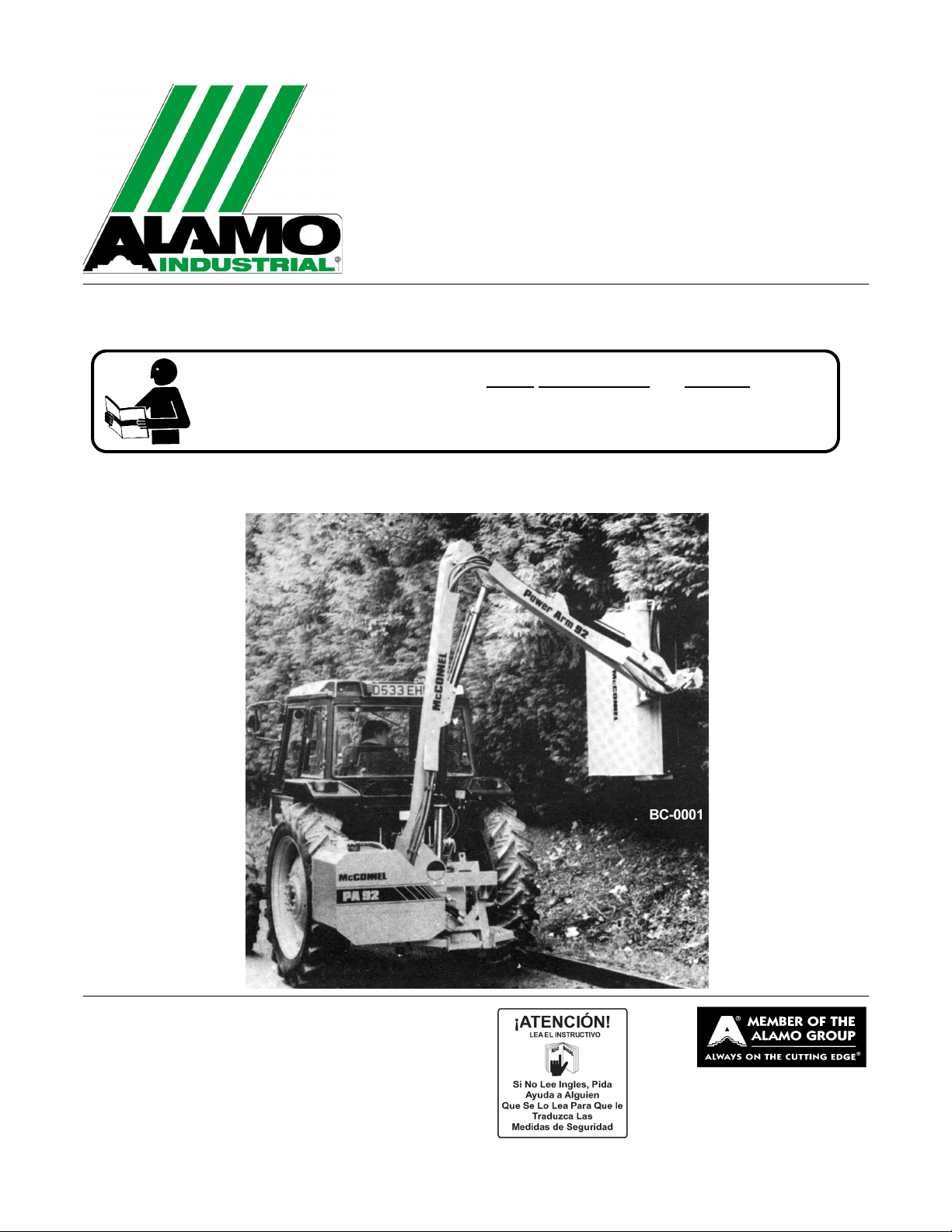
PA92
REAR-MOUNT
BOOM MOWER
Published 03/09 Part No. 7192859C
OPERATOR’S MANUAL
This Operator's Manual is an integral part of the safe operation of this machine and must
be maintained with the unit at all times. READ,
and Operation Instructions contained in this manual before operating the equipment. C01-
Cover
UNDERSTAND, and FOLLOW the Safety
ALAMO INDUSTRIAL®
1502 E. Walnut
Seguin, Texas 78155
830-372-3551
Email: parts@alamo-industrial.com
©2009 Alamo Group Inc.
$0.00
Page 2

To the Owner/Operator/Dealer
All implements with moving parts are potentially hazardous. There is no substitute for a cautious, safe-minded
operator who recognizes the potential hazards and follows reasonable safety practices. The manufacturer has
designed this implement to be used with all its safety equipment properly attached to minimize the chance of
accidents.
BEFORE YOU START!!Read the safety messages on the implement and shown in your manual. Observe the
rules of safety and common sense!
WARRANTY INFORMATION:
Read and understand the complete Warranty Statement found in this Manual. Fill out the Warranty Registration
Form in full and return it to within 30 Days. Make certain the Serial Number of the Machine is recorded on the
Warranty Card and on the Warranty Form that you retain.
Page 3

In order to reduce accidents and enhance the safe operation of mowers, Alamo Industrial, in cooperation
with other industry manufacturers has developed the AEM/FEMA Industrial and Agricultural Mower
Safety Practices video and guide book.
The video will familiarize and instruct mower-tractor operators in safe practices when using industrial
and agricultural mowing equipment. It is important that Every Mower Operator be educated in the operation of their mowing equipment and be able to recognize the potential hazards that can occur while operating a mower. This video, along with the mower operator’s manual and the warning messages on the
mower, will significantly assist in this important education.
Your Authorized Alamo Industrial Dealer may have shown this video and presented you a DVD Video
when you purchased your mower. If you or any mower operator have not seen this video, Watch the
Video, Read this Operator’s Manual, and Complete the Video Guidebook before operating your new
mower. If you do not understand any of the instructions included in the video or operator’s manual or if
you have any questions concerning safety of operation, contact your supervisor, dealer or Alamo Indus-
trial.
If you would like a VHS video tape of the video, please email AEMVideo@alamo-group.com or Fax
AEM VHS Video at (830) 372-9529 or mail in a completed copy of the form on the back of this page to
AEM VHS Video 1502 E Walnut Street, Seguin, TX 78155. and request the VHS video version. Please
include your name, mailing address, mower model and serial number.
Every operator should be trained for each piece of equipment (Tractor and Mower), understand the
intended use, and the potential hazards before operating the equipment.
Page 4

Alamo Industrial Division is willing to provide
one (1) AEM Mower Safety Practices Video
Please Send Me: VHS Format – AEM/FEMA Mower Operator Safety Video
DVD Format – AEM/FEMA Mower Operator Safety Video
Mower Operator’s Manual
AEM Mower Operator’s Safety Manual
Requester Name Phone:
Requester Address:
City
State
Zip Code
Mower Model: Serial Number:
Date Purchased: Dealer Salesperson:
Dealership Name: Dealership Location:
Mail to:
AEM Video Services
1502 E Walnut street
Seguin, TX 78155
Or Fax to:
(830) 372-9529
Or Email to:
AEMVideo@alamo-group.com
Page 5

TABLE OF CONTENTS
SAFETY SECTION ..............................................................................................................1-1
General Safety Instructions and Practices ......................................................................................................... 1-2
Operator Safety Instructions and Practices ....................................................................................................... 1-3
Equipment Operation Safety Instructions and Practices .................................................................................... 1-5
Connecting or Disconnecting Implement Safety Instructions and Practices .................................................... 1-11
Transporting Safety Instructions and Practices ............................................................................................... 1-12
Maintenance and Service Safety Instructions and Practices ........................................................................... 1-13
Concluding Safety Instructions and Practices .................................................................................................. 1-16
Decal Location ................................................................................................................................................. 1-17
Decal Description ............................................................................................................................................. 1-19
Federal Laws and Regulations ........................................................................................................................ 1-27
INTRODUCTION SECTION ................................................................................................. 2-1
ASSEMBLY SECTION ........................................................................................................ 3-1
TRACTOR SELECTION .................................................................................................................................... 3-2
Linkage Requirements ....................................................................................................................................... 3-2
Linkage Isolation ................................................................................................................................................ 3-2
Check Chains/ Stabilizers .................................................................................................................................. 3-2
Tractor Relief Valve ........................................................................................................................................... 3-2
Tractor Hydraulic Flow Rates ............................................................................................................................. 3-2
P.T.O. Shaft ....................................................................................................................................................... 3-2
Draft Control ....................................................................................................................................................... 3-2
TRACTOR PREPARATION ............................................................................................................................... 3-3
Fitting Operator Guard ....................................................................................................................................... 3-3
Wheel Width ....................................................................................................................................................... 3-4
Ballast Weight .................................................................................................................................................... 3-4
JOHN DEERE CONVERSION KIT (81- 30- 059) for Si Models ........................................................................ 3-4
DELIVERY ......................................................................................................................................................... 3-5
ATTACHMENT TO TRACTOR .......................................................................................................................... 3-5
Si Model ............................................................................................................................................................. 3-5
FITTING CONTROL UNIT IN CAB .................................................................................................................... 3-8
OIL REQUIREMENTS ....................................................................................................................................... 3-9
Tank ................................................................................................................................................................... 3-9
Gearbox ............................................................................................................................................................. 3-9
RUNNING UP PROCEDURE .......................................................................................................................... 3-10
PA92 Ti ............................................................................................................................................................ 3-10
PA92 Si ............................................................................................................................................................ 3-10
REMOVAL FROM TRACTOR ......................................................................................................................... 3-11
OPERATION SECTION ....................................................................................................... 4-1
Standard Equipment and Specifications ............................................................................................................ 4-3
OPERATOR REQUIREMENTS ......................................................................................................................... 4-4
TRACTOR REQUIREMENTS ............................................................................................................................ 4-5
ROPS and Seat Belt .......................................................................................................................................... 4-5
Operator Thrown Object Protection ................................................................................................................... 4-5
Tractor Lighting and SMV Emblem .................................................................................................................... 4-6
Tractor Ballast .................................................................................................................................................... 4-7
Page 6

Tractor Safety Devices ....................................................................................................................................... 4-7
Tractor Horsepower ........................................................................................................................................... 4-8
3-Point Hitch ...................................................................................................................................................... 4-8
Hydraulics .......................................................................................................................................................... 4-9
Front End Weight ............................................................................................................................................... 4-9
Power Take Off (PTO) ....................................................................................................................................... 4-9
GETTING ON AND OFF THE TRACTOR ......................................................................................................... 4-9
Boarding the Tractor ........................................................................................................................................ 4-10
Dismounting the Tractor ................................................................................................................................... 4-10
STARTING THE TRACTOR ............................................................................................................................ 4-11
Connecting Attaching Head to the Boom ......................................................................................................... 4-12
Connecting Mower Head Hydraulics ................................................................................................................ 4-12
PRE-OPERATION INSPECTION AND SERVICE ...........................................................................................4-14
Tractor Pre-Operation Inspection/Service ........................................................................................................ 4-14
Boom Unit Pre-Operation Inspection and Service ........................................................................................... 4-15
OPERATING THE BOOM MOWER ................................................................................................................ 4-21
Machine Controls ............................................................................................................................................. 4-21
Arm Controls .................................................................................................................................................... 4-22
Rotor Controls (Ti Only) ................................................................................................................................... 4-23
Engaging Drive ................................................................................................................................................ 4-24
Rotor Operating Speed .................................................................................................................................... 4-24
Forward Speed ................................................................................................................................................ 4-25
Tractor Position ................................................................................................................................................ 4-25
Operating Speed .............................................................................................................................................. 4-25
Working Close In and High .............................................................................................................................. 4-25
Breakaway Action ............................................................................................................................................ 4-26
Wire Trap ......................................................................................................................................................... 4-26
Removing Wire ................................................................................................................................................ 4-26
High Voltage Cables ........................................................................................................................................ 4-27
Hedge Cutting Procedure ................................................................................................................................ 4-27
Roller Positions ................................................................................................................................................ 4-30
Grass Cutting ................................................................................................................................................... 4-31
Lift Float Kit (Optional) ..................................................................................................................................... 4-31
DRIVING THE TRACTOR AND IMPLEMENT ................................................................................................. 4-32
Starting the Tractor .......................................................................................................................................... 4-33
Brake and Differential Lock Setting .................................................................................................................. 4-34
Transport Position ............................................................................................................................................ 4-34
Moving from the Transport to the Work Position .............................................................................................. 4-35
Driving the Tractor and Boom .......................................................................................................................... 4-36
OPERATING THE TRACTOR AND IMPLEMENT ........................................................................................... 4-37
OPERATING INSTRUCTIONS ........................................................................................................................ 4-37
Foreign Debris Hazards ................................................................................................................................... 4-39
Bystanders/Passersby Precautions ................................................................................................................. 4-39
Engaging the Power Take Off (PTO) .............................................................................................
Operating Speed and Ground Speed .............................................................................................................. 4-41
Operating the Mower ....................................................................................................................................... 4-41
Operating the Attached Mower Heads ............................................................................................................. 4-43
Shutting Down the Attached Head ................................................................................................................... 4-44
TRACTOR, BOOM, AND ATTACHED HEAD STORAGE ............................................................................... 4-44
DISCONNECTING THE MOWER ................................................................................................................... 4-45
TRANSPORTING THE TRACTOR AND IMPLEMENT ................................................................................... 4-46
Transporting on Public Roadways ................................................................................................................... 4-46
Hauling the Tractor and Implement .................................................................................................................. 4-49
TROUBLESHOOTING GUIDE ........................................................................................................................ 4-50
.................. 4-40
MAINTENANCE SECTION .................................................................................................. 5-1
Page 7

LUBRICATION ................................................................................................................................................... 5-2
HYDRAULIC SYSTEM ...................................................................................................................................... 5-3
Oil Supply ........................................................................................................................................................... 5-3
Filtration Maintenance ........................................................................................................................................ 5-3
HYDRAULIC HOSES ......................................................................................................................................... 5-3
Hose Replacement ............................................................................................................................................ 5-4
Hose Warranty ................................................................................................................................................... 5-4
P.T.O. GEARBOX .............................................................................................................................................. 5-4
FLAILHEAD ....................................................................................................................................................... 5-5
CABLES ............................................................................................................................................................. 5-5
HOSE CONNECTIONS ..................................................................................................................................... 5-6
STORAGE ......................................................................................................................................................... 5-8
PROPER TORQUE VALUES FOR FASTENERS .............................................................................................5-8
Page 8

Page 9

SAFETY SECTION
© 2008 Alamo Group Inc.
Safety Section 1-1
Page 10
SAFETY
General Safety Instructions and Practices
A careful operator is the best operator. Safety is of primary importance to the manufacturer and should be to
the owner/operator. Most accidents can be avoided by being aware of your equipment, your surroundings, and
observing certain precautions. The first section of this manual includes a list of Safety Messages that, if
followed, will help protect the operator and bystanders from injury or death. Read and understand these Safety
Messages before assembling, operating or servicing this Implement. This equipment should only be operated
by those persons who have read the manual, who are responsible and trained, and who know how to do so
responsibly.
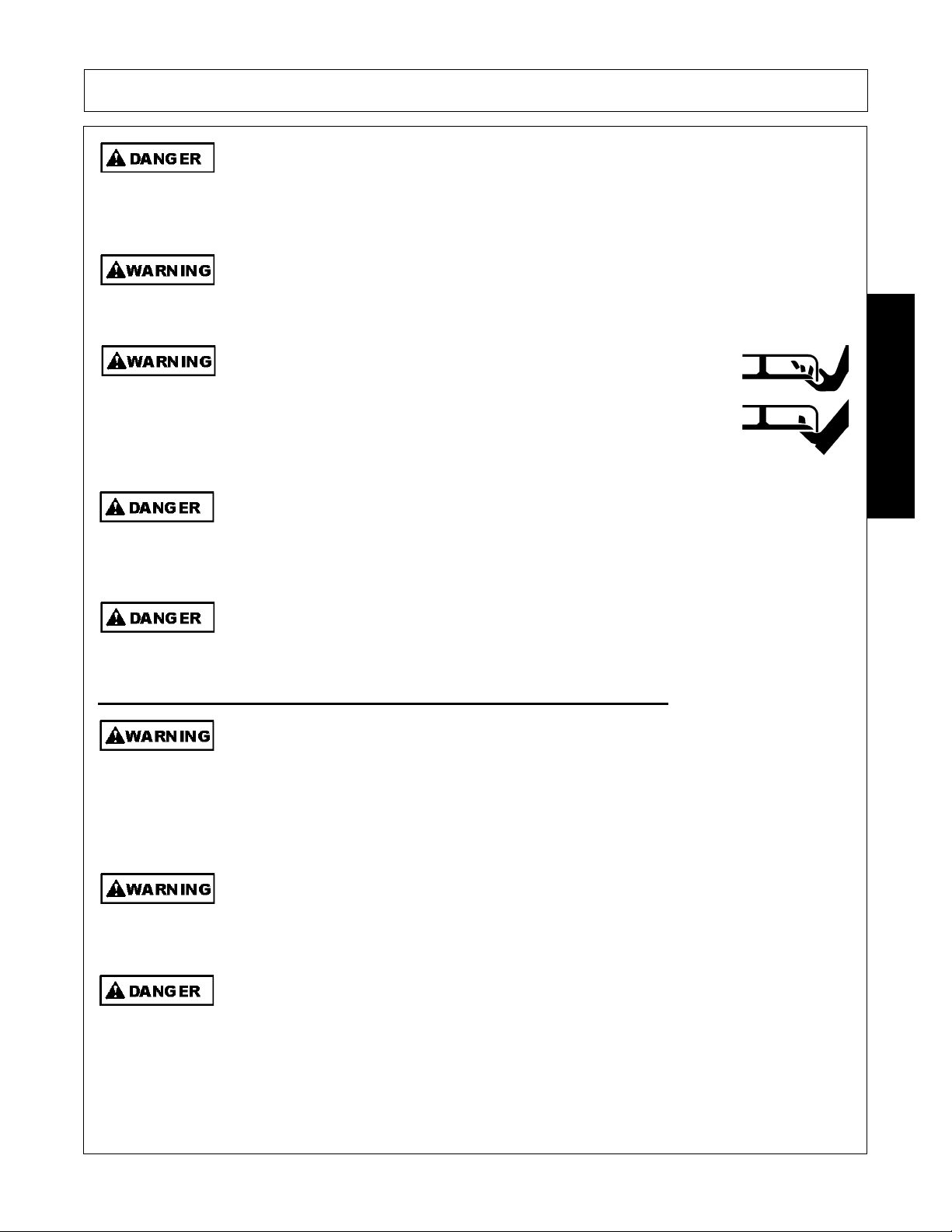
The Safety Alert Symbol combined with a Signal Word, as seen below, is used throughout this
manual and on decals which are attached to the equipment. The Safety Alert Symbol means:
“ATTENTION! BECOME ALERT! YOUR SAFETY IS INVOLVED!” The Symbol and Signal Word
are intended to warn the owner/operator of impending hazards and the degree of possible injury
faced when operating this equipment.
SAFETY
Practice all usual and customary safe working precautions and above all---remember safety is
up to YOU
. Only YOU can prevent serious injury or death from unsafe practices.
Indicates an imminently hazardous situation that, if not avoided, WILL result in DEATH OR
VERY SERIOUS INJURY.
Indicates an imminently hazardous situation that, if not avoided, COULD result in DEATH
OR SERIOUS INJURY.
Indicates an imminently hazardous situation that, if not avoided, MAY result in MINOR
INJURY.
Identifies special instructions or procedures that, if not strictly observed, could result in
damage to, or destruction of the machine, attachments or the environment.
NOTE: Identifies points of particular interest for more efficient and convenient operation or
repair.
(SG-1)
READ, UNDERSTAND, and FOLLOW the following Safety Messages. Serious injury or
death may occur unless care is taken to follow the warnings and instructions stated in the
Safety Messages. Always use good common sense to avoid hazards.
Si no lee ingles, pida ayuda a alguien que si lo lea para que le traduzca las
medidas de seguridad.
(SG-3)
(SG-2)
Engine Exhaust, some of its constituents, and certain vehicle components contain or emit
chemicals known to the state of California to cause cancer and birth defects or other
reproductive harm.
PA92 04/09 Safety Section 1-2
© 2009 Alamo Group Inc.
(SG-30)
Page 11
SAFETY
N
til
Battery posts, terminals and related accessories contain lead and lead compounds,
chemicals known to the state of California to cause cancer, birth defects or other
reproductive harm.
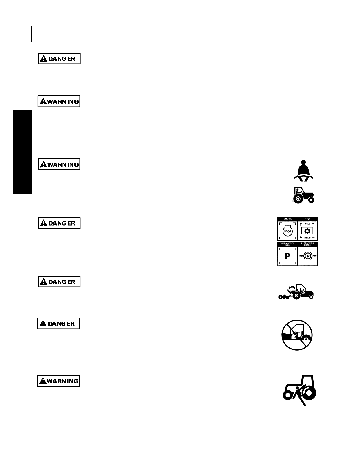
Operator Safety Instructions and Practices
The rotating parts of this machine continue to rotate even after the PTO has been turned off.
The operator should remain in his seat for 60 seconds after the brake has been set, the
PTO disengaged, the tractor turned off, and all evidence of rotation has ceased.
Never crawl under a raised Implement supported solely by the Tractor 3-Point hitch.
Release of the control lever or mechanical failure will result in the Implement falling and
possible injury or death. Always securely block up the Implement before crawling
underneath to perform repairs and service.
(SG-31)
“Wait a minute...Save a life!”
(S3PT-19)
(S3PT-10)
SAFETY
ever operate the Tractor or Implement un
you have read and completely understand this Manual, the Tractor Operator’s Manual, and each
of the Safety Messages found in the Manual or on the Tractor and Implement. Learn how to stop the tractor engine suddenly in an emergency.
Never allow inexperienced or untrained personnel to operate the Tractor
and Implement without supervision. Make sure the operator has fully
read and understood the manuals prior to operation.
(SG-4)
The operator and all support personnel should wear hard hats, safety
shoes, safety glasses, and proper hearing protection at all times for
protection from injury including injury from items that may be thrown by
the equipment.
(SG-16)
PROLONGED EXPOSURE TO LOUD NOISE MAY CAUSE
PERMANENT HEARING LOSS! Tractors with or without an Implement
attached can often be noisy enough to cause permanent hearing loss.
We recommend that you always wear hearing protection if the noise in
the Operator’s position exceeds 80db. Noise over 85db over an
extended period of time will cause severe hearing loss. Noise over 90db
adjacent to the Operator over an extended period of time will cause
permanent or total hearing loss. NOTE: Hearing loss from loud noise
[from tractors, chain saws, radios, and other such sources close to the
ear] is cumulative over a lifetime without hope of natural recovery.
(SG-I7)
PA92 04/09 Safety Section 1-3
© 2009 Alamo Group Inc.
Page 12
SAFETY
Al
ith th
Prol
U
tti
d
SAFETY
ways read carefully and comply fully w
e manufacturer’s
instructions when handling oil, solvents, cleansers, and any other
chemical agent.
(SG-22)
KEEP AWAY FROM ROTATING ELEMENTS to prevent entanglement
and possible serious injury or death.
(SG-24)
Never allow children to play on or around Tractor or Implement. Children can slip or fall off
the Equipment and be injured or killed. Children can cause the Implement to shift or fall
crushing themselves or others.
(SG-25)
NEVER use drugs or alcohol immediately before or while operating the
Tractor and Implement. Drugs and alcohol will affect an operator’s
alertness and coordination and therefore affect the operator’s ability to
operate the equipment safely. Before operating the Tractor or
Implement, an operator on prescription or over-the-counter medication
must consult a medical professional regarding any side effects of the
medication that would hinder their ability to operate the Equipment safely.
NEVER knowingly allow anyone to operate this equipment when their
alertness or coordination is impaired. Serious injury or death to the
operator or others could result if the operator is under the influence of
drugs or alcohol.
(SG-27)
onged operation may cause operator boredom and fatigue affecting safe operation.
Take scheduled work breaks to help prevent these potentially impaired operating
conditions. Never operate the Implement and Tractor in a fatigued or bored mental state
which impairs proper and safe operation.
se extreme caution when ge
ng onto the Implement to perform repairs, maintenance an
when removing accumulated material. Only stand on solid flat surfaces to ensure good
footing. Use a ladder or raised stand to access high spots which cannot be reached from
ground level. Slipping and falling can cause serious injury or death.
Avoid contact with hot surfaces including hydraulic oil tanks, pumps, motors, valves and
hose connections. Relieve hydraulic pressure before performing maintenance or repairs.
Use gloves and eye protection when servicing hot components. Contact with a hot surface
or fluid can cause serious injury from burns or scalding.
PA92 04/09 Safety Section 1-4
© 2009 Alamo Group Inc.
(SG-32)
(SG-33)
(SG-34)
Page 13
SAFETY
e
f
U
ldi
DO NOT operate this Implement on a Tractor that is not properly maintained. Should a
mechanical or Tractor control failure occur while operating, immediately shut down the
Tractor and perform repairs before resuming operation. Serious injury and possible death
could occur from not maintaining this Implement and Tractor in good operating condition.
(SG-36)
Avoid contact with hot surfaces of the engine or muffler. Use gloves and eye protection
when servicing hot components. Contact with a hot surface or fluid can cause serious injury
from burns or scalding.
(SG-38)
Do not put hands or feet under mower decks. Blade Contact can result
in serious injury or even death. Stay away until all motion has stopped
and the decks are securely blocked up.
(SGM-09)
Always keep a careful lookout and use extreme care when working around utility and
municipal obstructions. Never allow the Mower to contact any utility, municipal, or other
type structure. Clearly mark all mowing obstructions and consult local utility providers for
a safe code of operation.
(SPU-5)
Do not operate the implement while wearing loose fitting clothing. Entanglement of th
clothing with the rotating elements can result in serious injury or even death. Stay clear o
all rotating elements at all times. (SSP-03)
Equipment Operation Safety Instructions and Practices
Never leave the Tractor and Implement unattended while the Implement is in the lifted
position. Accidental operation of lifting lever or a hydraulic failure may cause sudden drop
of unit with injury or death by crushing. To properly park the implement when disconnecting
it from the tractor, lower the stand and put the retaining pin securely in place, or put a secure
support under the A-Frame. Lower the implement carefully to the ground. Do not put hands
or feet under lifted components.
(S3PT-1)
SAFETY
se extreme care when lowering or unfo
bystanders are close by or underneath the wings. Allow ample clearance around the
implement when folding or unfolding the wings. Use extreme caution around buildings or
overhead power lines.
(S3PT-05)
This Implement is wider than the Tractor. Be careful when operating or transporting this
equipment to prevent the Implement from running into or striking sign posts, guard rails,
concrete abutments or other solid objects. Such an impact could cause the Implement and
Tractor to pivot violently resulting in loss of steering control, serious injury, or even death.
Never allow the Implement to contact obstacles.
PA92 04/09 Safety Section 1-5
© 2009 Alamo Group Inc.
ng the implement’s wings. Make sure no
(S3PT-12)
Page 14
SAFETY
B
ill b
r
SAFETY
e sure you have adequate knowledge of the property you w
e working on. Take time to
make yourself aware of any area underground lines or cables. Contact with buried lines o
cable could result in serious injury or death. If in doubt about buried utility lines call 811
before digging or 1-800-258-0808.
(SBH-6)
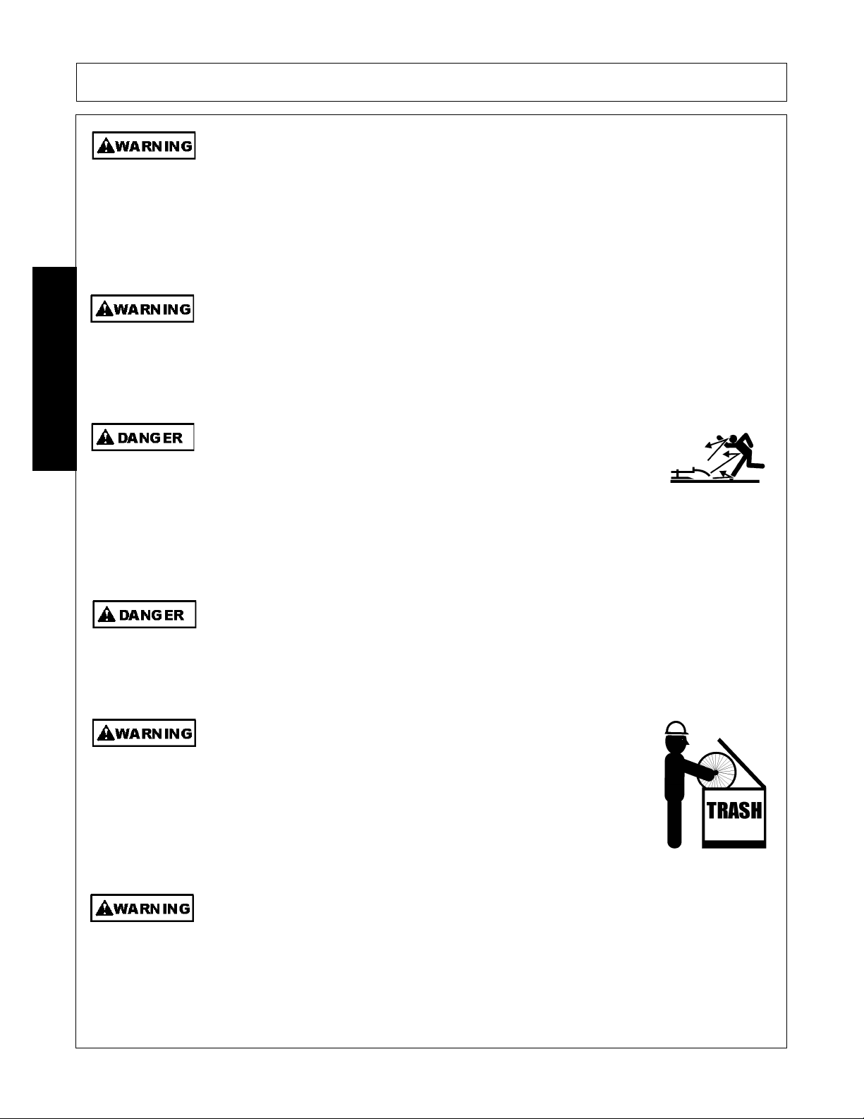
Do not operate Mower if excessive vibration exists. Shut down PTO and the Tractor
engine. Inspect the Mower to determine the source of the vibration. If Mower blades are
missing or damaged replace them immediately. Do not operate the mower until the
blades have been replaced and the Mower operates smoothly. Operating the Mower with
excessive vibration can result in component failure and broken objects to be thrown
outward at very high velocities. To reduce the possibility of property damage, serious injury,
or even death, never allow the Mower to be operated with blades missing.
(SFL-4)
Operate this Equipment only with a Tractor equipped with an approved rollover-protective system (ROPS). Always wear seat belts. Serious injury or
even death could result from falling off the tractor--particularly during a turnover
when the operator could be pinned under the ROPS.
(SG-7)
BEFORE leaving the tractor seat, always engage the brake and/or set
the tractor transmission in parking gear, disengage the PTO, stop the
engine, remove the key, and wait for all moving parts to stop. Place the
tractor shift lever into a low range or parking gear to prevent the tractor
from rolling. Never dismount a Tractor that is moving or while the engine
is running. Operate the Tractor controls from the tractor seat only.
(SG-9)
Never allow children or other persons to ride on the Tractor or Implement.
Falling off can result in serious injury or death.
Never allow children to operate, ride on, or come close to the Tractor or
Implement. Usually, 16-17 year-old children who are mature and
responsible can operate the implement with adult supervision, if they
have read and understand the Operator’s Manuals, been trained in
proper operation of the tractor and Implement, and are physically large
enough to reach and operate the controls easily.
Do not mount or dismount the Tractor while the tractor is moving. Mount
the Tractor only when the Tractor and all moving parts are completely
stopped.
PA92 04/09 Safety Section 1-6
(SG-12)
© 2009 Alamo Group Inc.
(SG-10)
(SG-11)
Page 15

SAFETY
I
difficulty duri
k
Start tractor only when properly seated in the Tractor seat. Starting a
tractor in gear can result in injury or death. Read the Tractor operators
manual for proper starting instructions.
Do not operate this Equipment with hydraulic oil or fuel leaking. Oil
and fuel are explosive and their presence could present a hazard. Do
not check for leaks with your hand! High-pressure oil streams from
breaks in the line could penetrate the skin and cause tissue damage
including gangrene. To check for a hose leak, SHUT the unit ENGINE
OFF and remove all hydraulic pressure. Wear oil impenetrable gloves,
safety glasses and use Cardboard to check for evidence of oil leaks. If
you suspect a leak, REMOVE the HOSE and have it tested at a Dealer.
If oil does penetrate the skin, have the injury treated immediately by a
physician knowledgeable and skilled in this procedure.
(SG-13)
(SG-15)
SAFETY
Never run the Tractor engine in a closed building or without adequate ventilation. The
exhaust fumes can be hazardous to your health.
(SG-23)
Do not exceed the rated PTO speed for the Implement. Excessive PTO speeds can cause
Implement driveline or blade failures resulting in serious injury or death.
(SG-26)
Operate the Tractor and/or Implement controls only while properly seated in the Tractor seat
with the seat belt securely fastened around you. Inadvertent movement of the Tractor or
Implement may cause serious injury or death.
n case of mechanical
ng operation, place the transmission in the par
(SG-29)
position, set the parking brake, shut down all power, including the PTO and the engine and
remove the key. Wait until all rotating motion has stopped before dismounting.
(SG-39)
PA92 04/09 Safety Section 1-7
© 2009 Alamo Group Inc.
Page 16
SAFETY
Ext
h
M
SAFETY
Do Not operate this equipment in areas where insects such as bees may attack you and/or
cause you to lose control of the equipment. If you must enter in such areas, use a tractor
with an enclosed Cab and close the windows to prevent insects from entering. If a tractor
cab is not available, wear suitable clothing including head, face, and hand protection to
shield you from the insects. Attacking insects can cause you to lose control of the tractor,
which can result in serious injury or death to you or bystanders. Never dismount a moving
tractor.
Mow only in conditions where you have clear visibility in daylight or with adequate artificial
lighting. Never mow in darkness or foggy conditions where you cannot clearly see at least
100 yards(90 m) in front and to the sides of the tractor and mower. Make sure that you can
clearly see and identify passersby, steep slopes, ditches, drop-offs, overhead obstructions,
power lines, debris and foreign objects. If you are unable to clearly see these type of items
discontinue mowing.
There are obvious and hidden potential hazards in the operation of this
Mower. REMEMBER! This machine is often operated in heavy brush
and in heavy weeds. The Blades of this Mower can throw objects if
shields are not properly installed and maintained. Serious injury or even
death may occur unless care is taken to insure the safety of the operator,
bystanders, or passersby in the area. Do not operate this machine with
anyone in the immediate area. Stop mowing if anyone is within 100 yards
of mower.
(SG-40)
(SGM-1)
(SGM-02)
The rotating parts of this machine have been designed and tested for rugged use.
However, the blades could fail upon impact with heavy, solid objects such as metal guard
rails and concrete structures. Such impact could cause the broken objects to be thrown
outward at very high velocities. To reduce the possibility of property damage, serious
injury, or even death, never allow the cutting blades to contact such obstacles.
reme care should be taken when operating near loose objects suc
as gravel, rocks, wire, and other debris. Inspect the area before
mowing. Foreign objects should be removed from the site to prevent
machine damage and/or bodily injury or even death. Any objects that
cannot be removed must be clearly marked and carefully avoided by the
operator. Stop mowing immediately if blades strike a foreign object.
Repair all damage and make certain rotor or blade carrier is balanced
before resuming mowing.
(SGM-05)
any varied objects, such as wire, cable, rope, or chains, can become entangled in the
operating parts of the mower head. These items could then swing outside the housing at
greater velocities than the blades. Such a situation is extremely hazardous and could result
in serious injury or even death. Inspect the cutting area for such objects before mowing.
Remove any like object from the site. Never allow the cutting blades to contact such items.
(SGM-06)
PA92 04/09 Safety Section 1-8
(SGM-4)
© 2009 Alamo Group Inc.
Page 17
SAFETY
M
The M
ifi
ow at the speed that you can safely operate and control the tractor and mower. The
correct mowing speed depends on terrain condition and grass type, density, and height of
cut. Normal ground speed range is from 2 to 5 mph(3-8 kph). Use slow mowing speeds
when operating on or near steep slopes, ditches, drop-offs, overhead obstructions, power
lines, or when debris and foreign objects are to be avoided.
Avoid mowing in reverse direction when possible. Check to make sure there are no
persons behind the mower and use extreme care when mowing in reverse. Mow only at a
slow ground speed where you can safely operate and control the tractor and mower.
Never mow an area that you have not inspected and removed debris or foreign material.
(SGM-08)
Do not mow with two machines in the same area except with Cab tractors with the windows
closed.
(SGM-11)
Follow these guidelines to reduce the risk of equipment and grass fires
while operating, servicing, and repairing the Mower and Tractor:
(SGM-07)
SAFETY
-Equip the Tractor with a fire extinguisher in an accesible location.
-Do Not operate the Mower on a Tractor with an underframe exhaust.
-Do Not smoke or have an open flame near the Mower and Tractor.
-Do Not drive into burning debris or freshly burnt areas.
-Ensure slip clutches are properly adjusted to prevent excessive slippage and plate heating.
-Never allow clippings or debris to collect near drivelines, slip clutches, and gearboxes.
Periodically shut down the Tractor and Mower and clean clippings and collected debris from
the mower deck.
(SGM-12)
ower is designed for certain mowing applications and is rated to cut up to a spec
size vegetation (see Mower Standard Equipment and Specifications). DO NOT use this
mower to cut vegetation above the Mower’s rated capacity or to cut any type of nonvegetative material. Only operate this Mower on a properly sized and equipped Tractor.
Operating this Mower in an application for which it is not designed and/or operating the
Mower with the wrong size Tractor can cause Mower component damage and equipment
failure resulting in possible serious injury or death.
(SGM-14)
Do not operate or pull the mower into standing water. When uplift or fan type mower blades
contact water they can be severely deflected downward causing possible failure of blade
resulting in serious boldly injury to the operator or bystanders.
(SGM-15)
c
PA92 04/09 Safety Section 1-9
© 2009 Alamo Group Inc.
Page 18
SAFETY
Use extreme caution when raising the Mower above ground level. Stop the Blades from
turning when the Mower is raised and passersby are within 100 yards. Raising the
Mower exposes the Cutting Blades which creates a potentially serious hazard and can
cause serious injury by objects thrown from the Blades or by contact with the Blades.
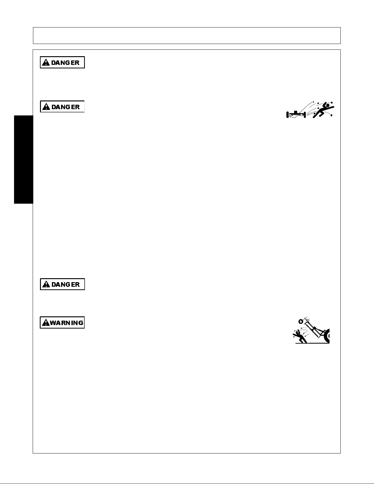
Rotary Mowers are capable under adverse conditions of throwing
objects for great distances (300 feet or more) and causing serious injury
or death. Follow safety messages carefully.
STOP MOWING IF PASSERSBY ARE WITHIN 100 YARDS UNLESS:
-Front and Rear Deflectors, Chain Guards, or Bands are installed and in good, workable
condition;
-Mower sections or Wings are running close to and parallel to the ground without exposed
Blades;
SAFETY
-Passersby are outside the existing thrown-object zone;
-All areas have been thoroughly inspected and all foreign material such as rocks, cans,
glass, and general debris has been removed.
(SPU-1)
NOTE: Where there are grass and weeds high enough to hide debris that could be struck
by the blades, the area should be: inspected and large debris removed, mowed at an
intermediate height, inspected, closely with any remaining debris being removed, and
mowed again at desired final height. (This will also reduce power required to mow, reduce
wear and tear on the Mower drivetrain, spread cut material better, reduce streaking, and
make the final cut more uniform).
Do not turn so sharp or lift mower so high to produce a severe "knocking" of the Driveline
which will cause accelerated wear and breakage of drive train components and could result
in possible injury from the separated Driveline sections.
Do not let the Blades turn when the Mower Deck is raised for any
reason, including clearance or for turning. Raising the Mower deck
exposes the Cutting Blades which creates a potentially serious hazard
and could cause serious injury or even death from objects thrown from
the Blades.
(SRM-01)
(SRM-04)
(SRM-07)
PA92 04/09 Safety Section 1-10
© 2009 Alamo Group Inc.
Page 19

SAFETY
Wh
PTO, it is i
Connecting or Disconnecting Implement Safety Instructions and Practices
DO NOT use a PTO adapter to attach a non-matching Implement driveline to a Tractor
PTO. Use of an adapter can double the operating speed of the Implement resulting in
excessive vibration, thrown objects, and blade and implement failure. Adapter use will also
change the working length of the driveline exposing unshielded driveline areas. Serious
bodily injury and/or equipment failure can result from using a PTO adapter. Consult an
authorized dealer for assistance if the Implement driveline does not match the Tractor PTO.
(S3PT-14)
Always shut the Tractor completely down, place the transmission in park, and set the
parking brake before you or anyone else attempts to connect or disconnect the Implement
and Tractor hitches.
Never operate the Tractor and Mower if the Implement input driveline is directly connected
to the Tractor transmission. Tractor braking distances can be substantially increased by
the momentum of the rotating Mower blades driving the Tractor transmission even though
the Tractor clutch has been disengaged. Install an over running clutch between the Tractor
PTO and the Mower driveline to prevent this potentially dangerous situation.
(S3PT-15)
(S3PT-16)
SAFETY
en attaching the Implement input driveline to the Tractor
connecting yoke spring activated locking collar slides freely and the locking balls are seated
securely in the groove on the Tractor PTO shaft. Push and pull the driveline back and forth
several times to ensure it is securely attached. A driveline not attached correctly to the
Tractor PTO shaft could come loose and result in personal injury and damage to the
Implement.
Before operating the Implement, check to make sure the Implement input driveline will not
bottom out or become disengaged. Bottoming out occurs when the inner shaft penetrates
the outer housing until the assembly becomes solid-it can shorten no more. Bottoming out
can cause serious damage to the Tractor PTO by pushing the PTO into the Tractor and
through the support bearings or downward onto the PTO shaft, breaking it off. A broken
driveline can cause personal injury.
(S3PT-17)
(S3PT-18)
mportant that the
PA92 04/09 Safety Section 1-11
© 2009 Alamo Group Inc.
Page 20
SAFETY
r
Transporting Safety Instructions and Practices
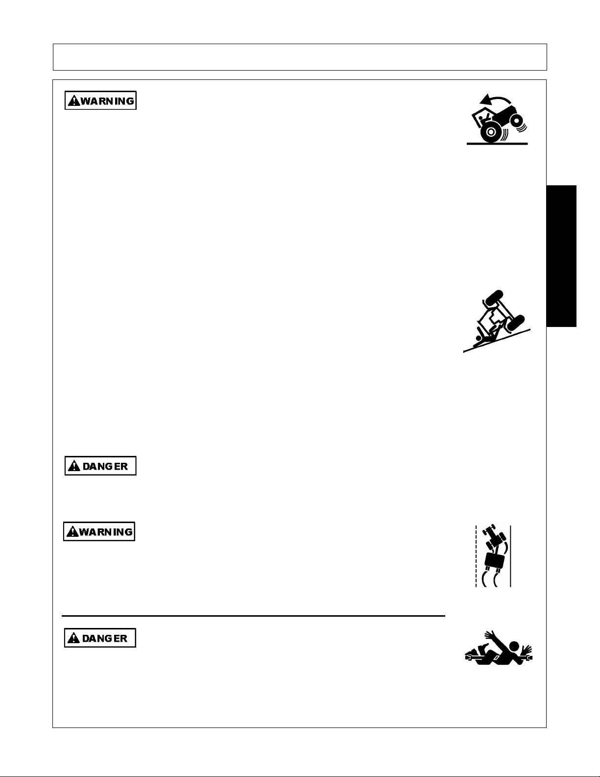
Be particularly careful when transporting the Implement with the Tractor. Turn curves or go
up hills only at a low speed and using a gradual steering angle. Rear mounted implements
move the center of gravity to the rear and remove weight from the front wheels. Make
certain, by adding front ballast, that at least 20% of the tractor’s weight is on the front wheels
to prevent rearing up, loss of steering control or Tractor tip-over. Slow down on rough o
uneven surfaces to prevent loss of steering control which could result in property damage
or possible injury. Do not transport unless 3-Point lift lever is fully raised and in the latched
transport position. Dropping implement in transport can cause serious damage to the
tractor and/or Implement and possibly cause the operator or others to be injured or killed.
(S3PT-02)
Allow sufficient clearance for the Implement to swing outward while turning. Implements
carried behind the Tractor will swing outside the tire path when making turns. Contacting a
SAFETY
solid object while turning will cause equipment damage and possible injury.
Make certain that the “Slow Moving Vehicle” (SMV) sign is installed in
such a way as to be clearly visible and legible. When transporting the
Equipment use the Tractor flashing warning lights and follow all local
traffic regulations.
(SG-6)
(S3PT-20)
PA92 04/09 Safety Section 1-12
© 2009 Alamo Group Inc.
Page 21
SAFETY
B
Only t
Transport only at speeds where you can maintain control of the
equipment. Serious accidents and injuries can result from operating this
equipment at high speeds. Understand the Tractor and Implement and how it handles
before transporting on streets and highways. Make sure the Tractor steering and brakes
are in good condition and operate properly.
Before transporting the Tractor and Implement, determine the proper transport speeds for
you and the equipment. Make sure you abide by the following rules:
Test the tractor at a slow speed and increase the speed slowly. Apply the Brakes smoothly
to determine the stopping characteristics of the Tractor and Implement. As you increase
the speed of the Tractor the stopping distance increases. Determine the maximum
transport speed not to exceed 20 mph (30 kph) for transporting this equipment.
Test the equipment at a slow speed in turns. Increase the speed through the turn only after
you determine that the equipment can be operated at a higher speed. Use extreme care
and reduce your speed when turning sharply to prevent the tractor and implement from
turning over. Determine the maximum turning speed for you and this equipment before
operating on roads or uneven ground.
Only transport the Tractor and Implement at the speeds which allow you to properly control
the equipment.
SAFETY
Be aware of the operating conditions. Do not operate the Tractor with weak or faulty brakes
or worn tires. When operating down a hill or on wet or rain slick roads, the braking distance
increases: use extreme care and reduce your speed. When operating in traffic always use
the Tractor’s flashing warning lights and reduce your speed. Be aware of traffic around you
and watch out for the other guy.
e particularly careful when transporting the Implement using the tractor. Turn curves or
go up or down hills only at a low speed and at a gradual steering angle. Make certain that
at least 20% of the tractor’s weight is on the front wheels to maintain safe steerage. Slow
down on rough or uneven surfaces.
ow the Implement behind a properly sized and equipped Tractor
which exceeds the weight of the Implement by at least 20%. DO NOT
tow the Implement behind a truck or other type of vehicle. Never tow the
Implement and another Implement connected in tandem. Never tow the
Implement at speeds over 20 MPH.
(SG-19)
(STI-01)
(STI-06)
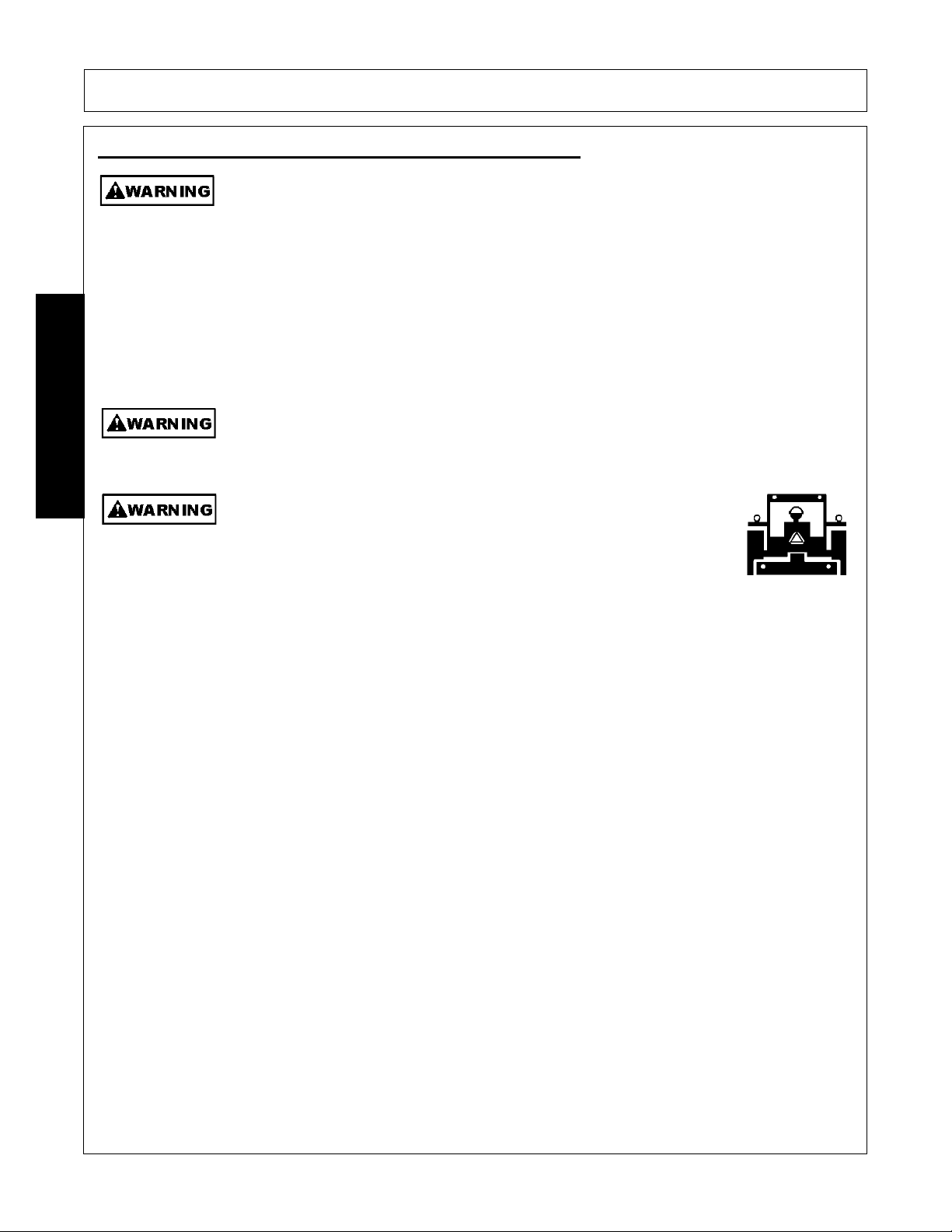
Maintenance and Service Safety Instructions and Practices
Make sure the PTO shield, integral driveline shields, and input shields
are is installed when using PTO-driven equipment. Always replace any
shield if it is damaged or missing.
(S3PT-8)
PA92 04/09 Safety Section 1-13
© 2009 Alamo Group Inc.
Page 22
SAFETY
SAFETY
Relieve hydraulic pressure prior to doing any maintenance or repair work
on the Implement. Place the Implement on the ground or securely
blocked up, disengage the PTO, and turn off the tractor engine. Push
and pull the Remote Cylinder lever in and out several times prior to
starting any maintenance or repair work.
Always disconnect the main PTO Driveline from the Tractor before performing service on
the Implement. Never work on the Implement with the tractor PTO driveline connected and
running. Rotating Parts, Blades or Drivelines could turn without warning and cause immediate entanglement, injury or death.
Always maintain the safety signs in good readable condition. If the safety signs are missing,
damaged, or unreadable, obtain and install replacement safety signs immediately.
Do not modify or alter this Implement. Do not permit anyone to modify or alter this
Implement, any of its components or any Implement function.
(S3PT-09)
(S3PT-11)
(SG-5)
(SG-8)
Never work under the Implement, the framework, or any lifted
component unless the Implement is securely supported or blocked up
to prevent sudden or inadvertent falling which could cause serious
injury or even death.
(SG-14)
Never attempt to lubricate, adjust, or remove material from the Implement while it is in
motion or while tractor engine is running.
(SG-20)
Periodically inspect all moving parts for wear and replace when
necessary with authorized service parts. Look for loose fasteners, worn
or broken parts, and leaky or loose fittings. Make sure all pins have
cotter pins and washers. Serious injury may occur from not maintaining
this machine in good working order.
(SG-21)
Do Not fill fuel tank while engine is running. Refuel only after engine has cooled down. If
fuel is spilled, move machine away from the area of the spill and avoid creating any source
of ignition until the gasoline has evaporated.
(SG-28)
PA92 04/09 Safety Section 1-14
© 2009 Alamo Group Inc.
Page 23
SAFETY
U
dli
B
ill b
I
diti
likelihood of
Perform service, repairs and lubrication according to the maintenance section. Ensure the
unit is properly lubricated as specified in the lubrication schedule and all bolts and nuts are
properly torqued. Failure to properly service, repair and maintain this Implement in good
operating condition could cause component failure and possible serious injury or even
death.
(SG-35)
se caution and wear protective gloves when han
ng sharp objects such as blades,
knives, and other cutting edges. Be alert to worn component surfaces which have sharp
edges. Sharp surfaces can inflict severe laceration injuries if proper hand protection is not
worn.
(SG-37)
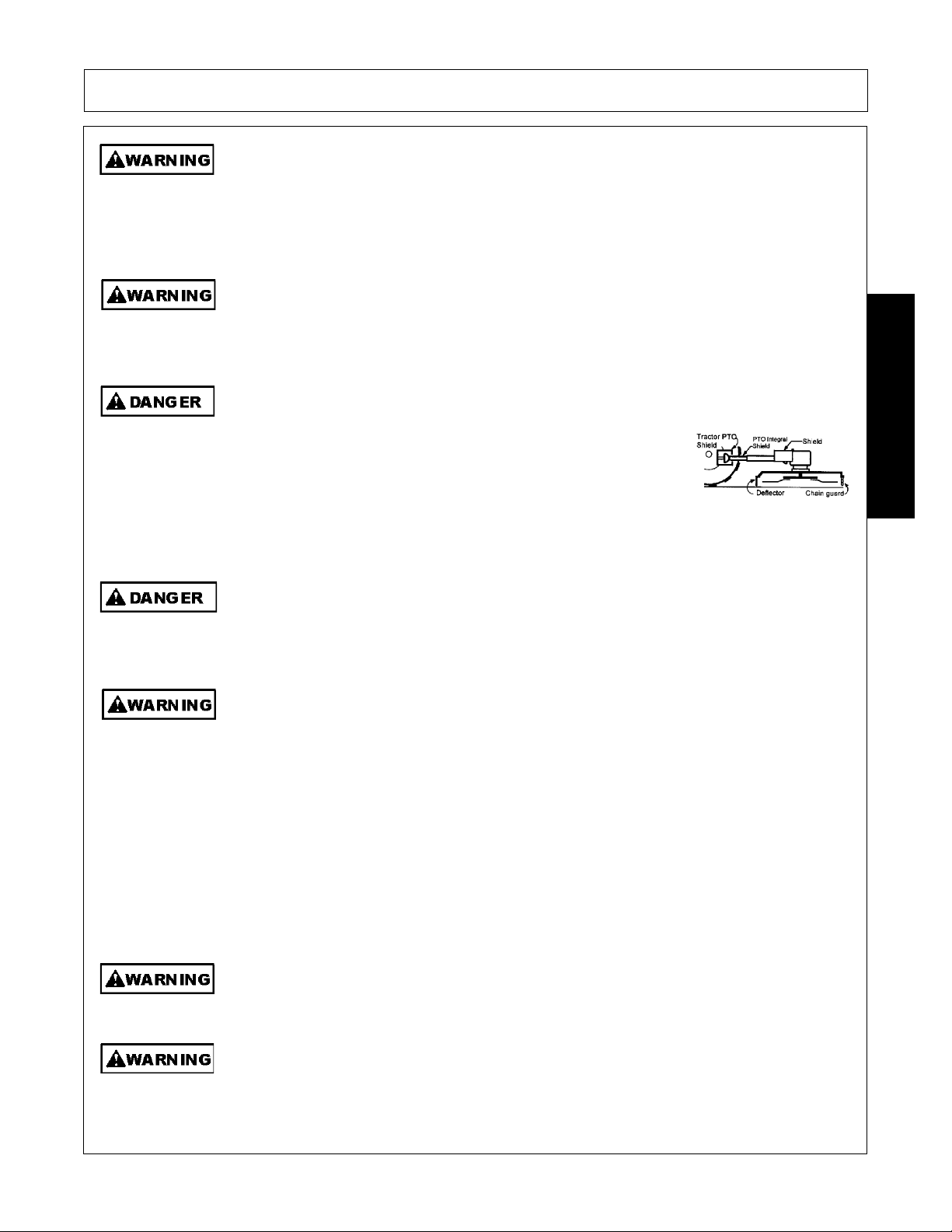
All Safety Shields, Guards and Safety devices including (but not limited to) - the Deflectors, Chain Guards, Steel Guards, Gearbox
Shields, PTO integral shields, and Retractable Door Shields should
be used and maintained in good working condition. All safety
devices should be inspected carefully at least daily for missing or
broken components. Missing, broken, or worn items must be
replaced at once to reduce the possibility of injury or death from
thrown objects, entanglement, or blade contact.
(SGM-3)
Replace bent or broken blades with new blades. NEVER ATTEMPT TO STRAIGHTEN,
WELD, OR WELD HARDFACING ON BLADES SINCE THIS WILL LIKELY CRACK OR
OTHERWISE DAMAGE THE BLADE WITH SUBSEQUENT FAILURE AND POSSIBLE
SERIOUS INJURY FROM THROWN BLADES.
(SGM-10)
DO NOT weld or repair rotating mower components. Welds and other repairs may cause
severe vibration and/or component failure resulting in part being thrown from the mower
causing serious bodily injury. See your Authorized Dealer for proper repairs.
(SGM-13)
SAFETY
PARTS INF O RM AT IO N
Alamo Industrial mowers use balanced and matched system components for blade carriers, blades,
cuttershafts, knives, knife hangers, rollers, drivetrain components, and bearings. These parts are made and
tested to Alamo Industrial specifications. Non-genuine "will fit" parts do not consistently meet these
specifications. The use of “will fit” parts may reduce mower performance, void mower warranties, and present
a safety hazard. Use genuine Alamo Industrial mower parts for economy and safety.
(SPRM-1)
SEE YOUR ALAMO DEALER
e sure you have adequate knowledge of the property you w
e working on. Take time to
make yourself aware of any area underground lines or cables. Contact with buried lines
or cable could result in serious injury or death.
n wet con
ons where there is a
certain that this material is removed before traveling on public roadways.
PA92 04/09 Safety Section 1-15
© 2009 Alamo Group Inc.
(STL-1)
material collecting on the Implement, make
(STL-7)
Page 24

SAFETY
Concluding Safety Instructions and Practices
In addition to the design and configuration of this Implement, including Safety Signs and Safety Equipment,
hazard control and accident prevention are dependent upon the awareness, concern, prudence, and proper
training of personnel involved in the operation, transport, maintenance, and storage of the machine. Refer
also to Safety Messages and operation instruction in each of the appropriate sections of the Tractor and
Equipment Manuals. Pay close attention to the Safety Signs affixed to the Tractor and Equipment.
(SG-18)
SAFETY
PA92 04/09 Safety Section 1-16
© 2009 Alamo Group Inc.
Page 25
SAFETY
Decal Location
NOTE: Alamo Industrial supplies safety decals on this product to promote safe operation. Damage to the
decals may occur while in shipping, use, or reconditioning. Alamo Industrial cares about the safety of its
customers, operators, and bystanders, and will replace the safety decals on this product in the field, free of
charge (Some shipping and handling charges may apply). Contact your Alamo Industrial dealer to order
replacement decals.
SAFETY
PA92 04/09 Safety Section 1-17
© 2009 Alamo Group Inc.
Page 26

SAFETY
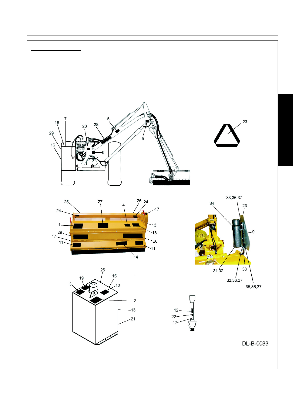
ITEM PART NO. QTY LEVEL DESCRIPTION
1. 002369 1 DANGER Multiple Hazard Flail
2. 02958241 1 DANGER Multiple Hazard Boom
3. 02965262 1 DANGER Oil Leak/Penetration
4. 02965100 1 INSTRUCT Use Genuine Alamo Industrial Parts
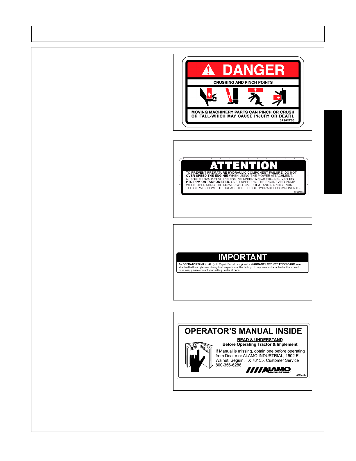
5. 02962764 2 DANGER Pinch Points/Scissors
6. 02962765 1 DANGER Multiple Hazard/Crushing
7. 02965093 1 ATTENTION Do not over speed engine
8. 00763977 1 NOTICE Operator’s Manual Shipped with Equipment
9. 02977417 1 NOTICE Operator’s Manual Inside
10. 03200437 1 WARNING Pressurized Tank
11. 00769737 1 DANGER Keep Away Thrown Objects
12. 00756005 1 DANGER Rotating Driveline, Entanglement
13. 00756007 1 DANGER Use/Repair Shields & Guards
14. 00756485 1 DANGER Blades, Thrown Objects
SAFETY
15. 00756494 1 DANGER Driveline Hazards
16. 02958241 1 DANGER Boom Mower Multi-Hazard
17. 000678 3 INSTRUCT Grease Fitting Inside
18. 000108 1 INSTRUCT Flail Operating Instructions
19. 02966305 1 INSTRUCT Use Universal Hyd Oil
20. 1290030 1 INSTRUCT EP90 Oil in Speed Increaser
21. 00725746 1 PELIGRO Spanish Warning
22. D103 1 WARNING 540 PTO
23. 03200347 1 REFLECT SMV Sign
24. 1458392 2 REFLECT Red
25. 1458393 2 REFLECT Amber
26. 00773723 1 PELIGRO Rotating Driveline Translation
27. 02976881 1 INSTRUCT Mowing Safety Tips
28. 001651 2 LOGO NAME Alamo Industrial
29. 001650 1 LOGO Alamo Industrial
30. NFS 1 SER PLT Serial Plate
31. 7191852C 1 _________ PA91 Operator’s Manual
32. 02977046 1 _________ AEM Mower Safety Manual
33. 02153100 2 _________ Bolt
34. 00776031 1 _________ Operator’s Manual Canister
35. 10058000 1 _________ Bolt
36. 02919924 3 _________ Locknut
37. 00024100 3 _________ Flatwasher
38. 02982492 1 _________ Bracket, Canister
NOTE: Alamo Industrial supplies safety decals on this product to promote safe operation. Damage to the
decals may occur while in shipping, use, or reconditioning. Alamo Industrial cares about the safety of its
customers, operators, and bystanders, and will replace the safety decals on this product in the field, free of
charge (some shipping and handling charges may apply). Contact your Alamo Industrial dealer to order
replacement decals.
PA92 04/09 Safety Section 1-18
© 2009 Alamo Group Inc.
Page 27
SAFETY
Decal Description
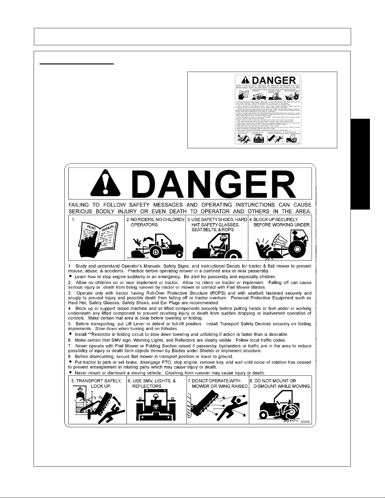
Danger! Mult-Hazard Warning. Failing to follow
these Safety Messages and Operating Instructions
can cause serious bodily injury or even death to
operator and others in the area.
P/N 002369
SAFETY
PA92 04/09 Safety Section 1-19
© 2009 Alamo Group Inc.
Page 28
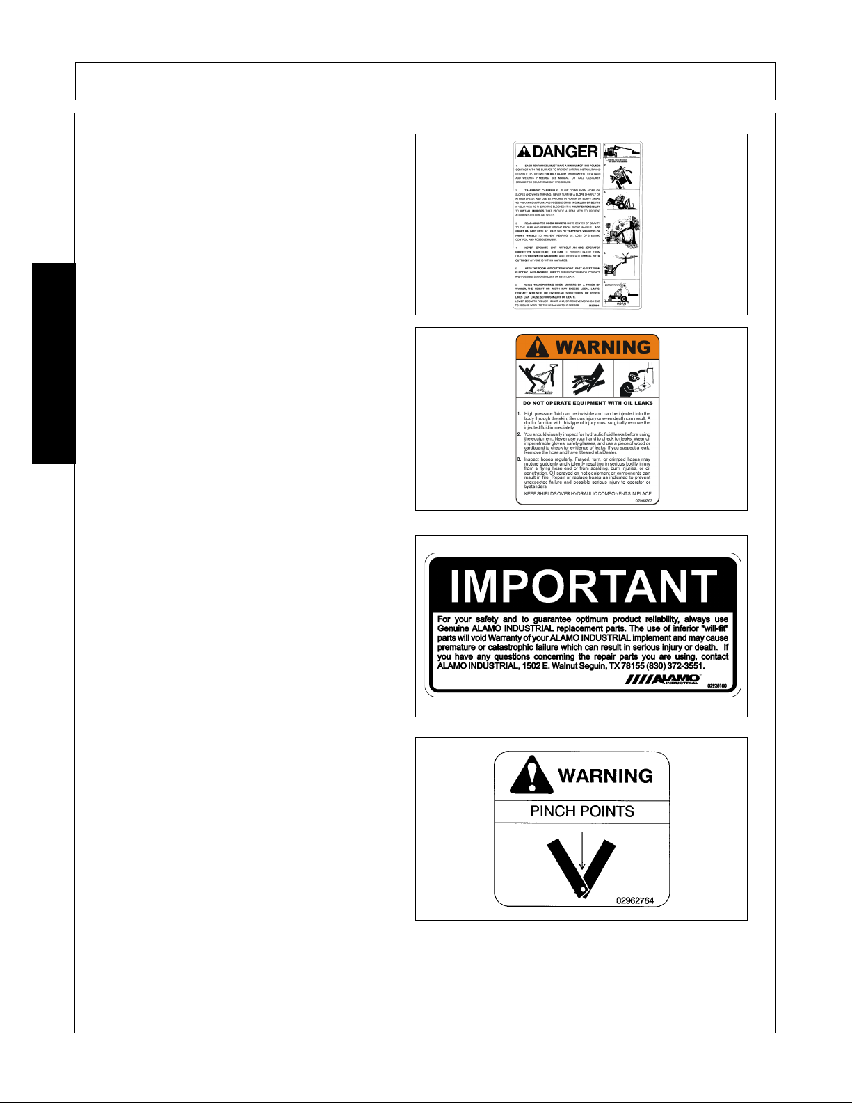
DANGER! - Multi-Hazard Boom. Take precautions
while transporting and operating Boom Unit.
P/N 02958241
WARNING! Failure to INSPECT and REPAIR or
REPLACE Hoses may allow worn Hoses to rupture
SUDDENLY and VIOLENTLY with resulting serious
BODILY INJURY from SCALDING or FIRE with
SAFETY
resulting BURN INJURY or DEATH.
SAFETY
P/N 02965262
IMPORTANT - Use only Genuine Alamo Industrial
replacement parts.
P/N 02925100
WARNING! Pinch Points
P/N 02962764
PA92 04/09 Safety Section 1-20
© 2009 Alamo Group Inc.
Page 29
SAFETY
DANGER! Crushing and Pinch Points.
Moving machiney parts can pinch or crush or fallwhich may cause injury or death.
P/N 02962765
INFORMATION - To prevent premature hydraulic
component failure, do not over speed the engine.
When using the mower attachment, operate tractor
at the engine speed which will deliver 540 PTO
RPM on Tachometer. Over speeding the engine
and pump when operating the mower will overheat
and rapidly ruin the oil which will decrease the life
of the hydraulic components.
P/N 02965093
Operator's Manual (with repair parts) and warranty
was attached to this implement during final
inspection.
SAFETY
P/N 00763977
INSTRUCTIONS - Read Operator’s Manual and
Understand, before operating Tractor and Implement.
P/N 02977417
PA92 04/09 Safety Section 1-21
© 2009 Alamo Group Inc.
Page 30
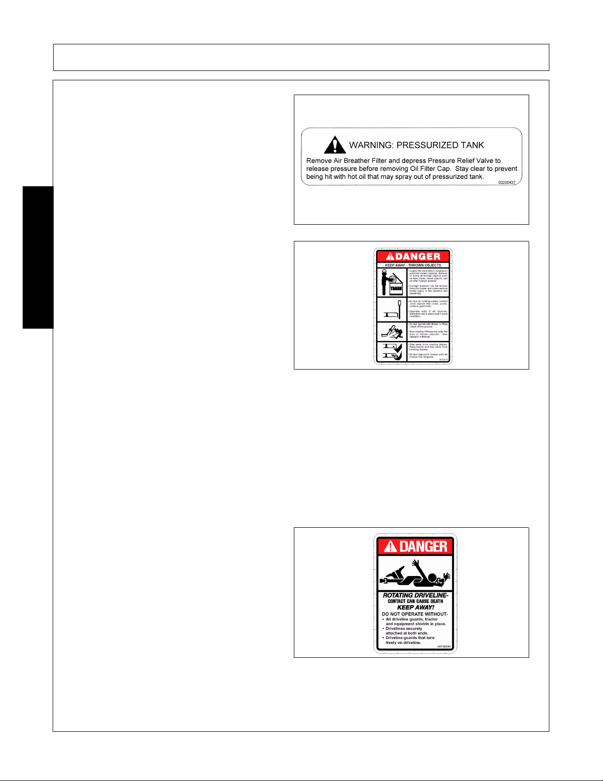
WARNING: Pressurized Tank
03200437
DANGER! Keep Away Thrown Objects.
Inspect the area before mowing for potential mower
hazards. Remove or avoid all foreign objects such
SAFETY
as wire, cable, metal objects, and all other foreign
material.
Foreign material can be thrown from the mower
and cause serious bodily injury to the operator and
passerby.
Do Not let rotating blades contact solid objects like
rocks, posts, curbs or guard rails.
Operate only if all Guards, Deflectors are in place
and in good condition.
Do Not operate with Mower or Wing raised off the
ground.
Stop mowing if Passersby enter the area of thrown
objects. (See Operator’s Manual)
Stay away from rotating blades. Keep hands and
feet away from rotating blades.
Do Not approach mower until all motion has
stopped.
P/N 00769737
SAFETY
DANGER! Rotating Driveline Keep Away, Contact
can cause death.
P/N 00756005
PA92 04/09 Safety Section 1-22
© 2009 Alamo Group Inc.
Page 31

SAFETY
WARNING! Keep all safety shielding installed,
repaired and replaced when damaged so that
machine stays in safe condition.
P/N 00756007
DANGER! Keep Away - Rotating Blades
P/N 00756485
DANGER! Make certain that drivelines are correct
length and are securely attached.
SAFETY
P/N 00756494
DANGER! - Multi-Hazard Boom. Take precautions
while transporting and operating Boom Unit.
P/N 02958241
PA92 04/09 Safety Section 1-23
© 2009 Alamo Group Inc.
Page 32

Information that Grease Fitting is present and must
apply grease.
P/N 000678
Instructions to properly lubricate and check mower
for potential problems prior to operation.
SAFETY
SAFETY
P/N 000108
INFORMATION - Attention - Service Hydraulic
System with Universal Tractor Hydraulic Oil. Alamo
Group part Number 02966307.
02966305
Peligro Translation, If you do not know how to read
English, please find someone who knows how to
read English.
P/N 00725746
PA92 04/09 Safety Section 1-24
© 2009 Alamo Group Inc.
Page 33

SAFETY
WARNING! Avoid Bodily Injury, Use 540RPM PTO
Speed Only.
P/N D103
Slow Moving Vehicle Decal. Keep SMV reflector
clean and visible. DO NOT transport or operate
without the SMV.
P/N 03200347
Red Reflector. Keep reflectors clean and visible.
SAFETY
P/N 1458392
Amber Reflector. Keep reflectors clean and visible.
P/N 1458393
PA92 04/09 Safety Section 1-25
© 2009 Alamo Group Inc.
Page 34

PELIGRO! Spanish Translation for Driveline Safety
P/N 00773723
ALAMO INDUSTRIAL LOGO
SAFETY
SAFETY
P/N 001651
ALAMO NAME LOGO.
P/N 001650
Read Operator’s Manual! The operator’s manual is
located inside this canister. If the manual is
missing order one from your dealer.
P/N 00776031
PA92 04/09 Safety Section 1-26
© 2009 Alamo Group Inc.
Page 35

SAFETY
Federal Laws and Regulations
This section is intended to explain in broad terms the concept and effect of federal laws and regulations
concerning employer and employee equipment operators. This section is not intended as a legal
interpretation of the law and should not be considered as such.
Employer-Employee Operator Regulations
U.S. Public Law 91-596 (The Williams-Steiger Occupational and Health Act of 1970) OSHA
This Act Seeks:
“...to assure so far as possible every working man and woman in the nation safe and healthful working
conditions and to preserve our human resources...”
DUTIES
Sec. 5 (a) Each employer-
(1) shall furnish to each of his employees employment and a place of employment which are free from
recognized hazards that are causing or are likely to cause death or serious physical harm to his employees;
(2) shall comply with occupational safety and health standards promulgated under this Act.
(b) Each employee shall comply with occupational safety and health standards and all rules, regulations and
orders issued pursuant to this Act which are applicable to his own actions and conduct.
OSHA Regulations
OSHA regulations state in part: “At the time of initial assignment and at least annually thereafter, the employer
shall instruct every employee in the safe operation and servicing of all equipment with which the employee is,
or will be involved.”
Employer Responsibilities:
To ensure employee safety during Tractor and Implement operation, it is the employer’s responsibility to:
1. Train the employee in the proper and safe operation of the Tractor and Implement.
SAFETY
2. Require that the employee read and fully understand the Tractor and Implement Operator’s manual.
3. Permit only qualified and properly trained employees to operate the Tractor and Implement.
4. Maintain the Tractor and Implement in a safe operational condition and maintain all shields and guards on the
equipment.
5. Ensure the Tractor is equipped with a functional ROPS and seat belt and require that the employee operator
securely fasten the safety belt and operate with the ROPS in the raised position at all times.
6. Forbid the employee operator to carry additional riders on the Tractor or Implement.
7. Provide the required tools to maintain the Tractor and Implement in a good safe working condition and provide the
necessary support devices to secure the equipment safely while performing repairs and service.
8. Require that the employee operator stop operation if bystanders or passersby come within 25 feet.
Child Labor Under 16 Years of Age
Some regulations specify that no one under the age of 16 may operate power machinery. It is your
responsibility to know what these regulations are in your own area or situation. (Refer to U.S. Dept. of
Labor, Employment Standard Administration, Wage & Home Division, Child Labor Bulletin #102.)
PA92 04/09 Safety Section 1-27
© 2009 Alamo Group Inc.
Page 36

Page 37

Page 38

Page 39

Page 40

Page 41

Page 42

Page 43

Page 44

Page 45

Page 46

Page 47

Page 48

Page 49

Page 50

Page 51

Page 52

Page 53

Page 54

Page 55

Page 56

Page 57

Page 58

Page 59

Page 60

Page 61

Page 62

Page 63

Page 64

Page 65

Page 66

Page 67

Page 68

Page 69

Page 70

Page 71

Page 72

Page 73

Page 74

Page 75

Page 76

Page 77

Page 78

Page 79

Page 80

Page 81

INTRODUCTION SECTION
© 2009 Alamo Group Inc.
Introduction Section 2-1
Page 82

INTRODUCTION
Made for use with smaller tractors in the 35 HP range, the rear mounted PA92 is your first choice when you
have the need to get in those hard to reach areas such as ditches and culverts to take care of light duty
vegetation. Stretch around waterways or ponds or mow along the roadside with ease. Grounds and roadway
maintenance is simplified when you have this boom on your team.
The PA92 mounts to the rear of the tractor utilizing a 3-point hitch. This allows for ease of disconnect and
convenient storage on a jackstand when not in use.
The controls are located at the operator’s fingertips. These cable controls are connected to the hydraulic
system located away from the driver in case of hose failure.
The boom arms are two-piece and use parallel linkage. These strong arms are made of A50 grade square
steel tubing. All of the hydraulic systems; pumps, hoses and connections are strategically placed to prevent
damage from obstacles such as fencing tree-limbs, etc. Boom reach is approximately 14’ when fully extended.
A hydraulic lift cylinder is strategically placed for maximum clearance when boom is fully extended.
A self-contained hydraulic system bypasses utilizing tractor hydraulics which allows for use on smaller tractors
with a minimum of 35 HP.
The 48” flail head is also available for areas that need a precise cut such as parks, playgrounds, and school
grounds.
Rotary cutting head is made for cutting light vegetation up to 2” in diameter, the rotary head has a cutting
INTRODUCTION
swatch of 59 -3/4”. Featuring two 1/2” x 4” x 19” tempered steel blades, this head is an asset not only around
ponds and waterways, but also in roadside applications.
Indicates an imminently hazardous situation that, if not avoided, WILL result in DEATH OR
VERY SERIOUS INJURY.
Indicates an imminently hazardous situation that, if not avoided, COULD result in DEATH
OR SERIOUS INJURY.
Indicates an imminently hazardous situation that, if not avoided, MAY result in MINOR
INJURY.
Identifies special instructions or procedures that, if not strictly observed, could result in
damage to, or destruction of the machine, attachments or the environment.
PA92 04/09 Introduction Section 2-2
© 2009 Alamo Group Inc.
Page 83

INTRODUCTION
INTRODUCTION
These hydraulically driven mowers are designed for light-duty work. They can mow pastures and control grass
and weeds on highways or industrial sites.
For Non-Agricultural use, OSHA, ASAE, SAE and ANSI standards require the use of Chain
Guards, Deflectors, or Solid Skirts at all times. The Mower manufacturer strongly
recommends the use of Chain Guards, Deflectors, or Solid Skirts for Agricultural purposes
as well to reduce the risk of property damage, serious bodily injury, or even death from
objects thrown out by or from contact with the Cutting Blades.
At least 20% of the tractor’s total weight must be on the front tires with the Mower lifted to
provide adequate traction for safe steering under good conditions. Slow down on hills, rough
terrain, and curves.
Mower Orientation: Front and rear, and left and right are determined by the normal direction of travel (the same
as on your automobile).
PA92 04/09 Introduction Section 2-3
© 2009 Alamo Group Inc.
Page 84

INTRODUCTION
ATTENTION OWNER/ OPERATOR
BEFORE OPERATING THIS MACHINE:
1. Carefully read the Operator’s Manual, completely understand the Safety Messages and instructions, and
know how to operate correctly both the Mower and Power Unit.
2. Fill out the Warranty Card in full. Be sure to answer all questions, including the Serial Number of the Mower.
Mail promptly using the return envelope included with the Operator’s Manual.
NOTE: Warranties are honored only if completed “Owner Registration and Warranty” forms are received by
Alamo Group within thirty days of delivery of the mower.
3. Record the Mower Model and Serial Numbers on the Warranty page at the end of the Operator’s Manual.
Keep this as part of the permanent maintenance file for the Mower.
INTRODUCTION
PA92 04/09 Introduction Section 2-4
© 2009 Alamo Group Inc.
Page 85

ASSEMBLY SECTION
© 2009 Alamo Group Inc.
Assembly Section 3-1
Page 86

ASSEMBLY
TRACTOR SELECTION
Linkage Requirements
The Power Arm 92 fit almost any tractor with a Category II linkage.
Linkage Isolation
Although it may be possible to operate the semi-independent version of the PA92 without linkage isolation, a
severe strain would be put upon the attachment yoke and pins. Most modern tractors are equipped with a
ready means of providing linkage isolation through a conveniently operated valve.
Linkage isolation is not required on the fully independent model of the PA92 and the tractors hydraulic controls
should be neutralized.
Check Chains/ Stabilizers
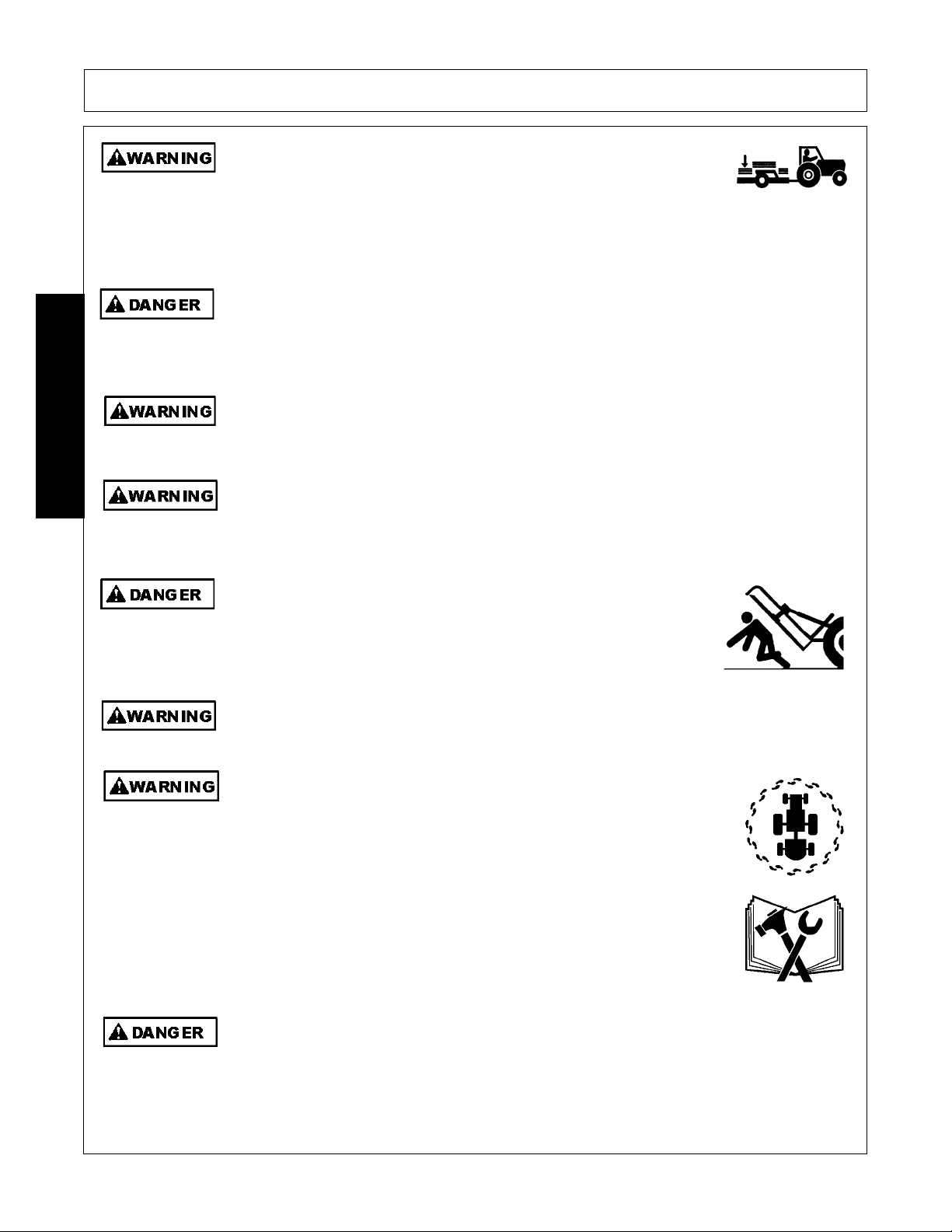
To hold the machine firmly in position, check chains or stabilizer bars must be fitted. It is dangerous to operate
the machine without these elements.
Tractor Relief Valve
ASSEMBLY
The main relief valve in the hedger hydraulic control unit is set at 1800 PSI (140 Bar). Therefore, if operating
the PA92 in semi-independent form, the tractor’s relief valve setting must be at least a little above 1800 PSI for
satisfactory operation.
Tractor Hydraulic Flow Rates
Oil flow rates are not crucial when operating a semi-independent PA92. Flow rates of up to 10 GPM (45 1/min.)
should not have any adverse to the inching response that it is sometimes required from the control valve.
P.T.O. Shaft
Tractor must be equipped with live drive-independent PTO shaft to enable forward movement to be halted
while the flail head continues to operate.
Draft Control
Loads imposed through the draft sensing mechanism will not normally be sufficient to put a strain on the
tractor. However, any provision for draft control should be set to minimum response. Where a draft control
rocker is fitted with a dead pin this should be utilized.
PA92 04/09 Assembly Section 3-2
© 2009 Alamo Group Inc.
Page 87

ASSEMBLY
TRACTOR PREPARATION
Fitting Operator Guard
A tractor fitted with a cab that has a safety glass windows should be used whenever possible. This is a basic
safety precaution applicable to the use of all flail-type hedge trimmers.
Power arms are supplied with an operator guard kit (Part No. 73 13 324) which must be fitted to the tractor
before commencing work.
ASSEMBLY
It consists of two areas of wire mesh which can be shaped to suit and be secured against the cab window with
a spring loaded hooks; the upper edge being anchored around the cab gutter and the lower edge around the
mudwing.
According to the great range of cabs, it may be necessary to adapt or make brackets to secure the mesh.
If the flail is operated on a tractor that is equipped with a a safety frame or roll bar only, an additional frame
must be made and fixed to the tractor onto which the guard mesh can be secured. In addition to the guard
mesh, a sheet of Polycarbonate transparent glazing must be fitted to the frame to provide further operator
protection. This material must also be used when the cab does not have safety glass installed.
The operator guard kit supplied is suitable for all standard applications; i.e., rear mounted on a conventional
tractor. For other applications, additional mesh guarding may need to be constructed to give adequate operator
protection. A guideline to follow when assessing any additional guarding that may be required is that the
operator must always be looking at the flail head through the mesh when it is in any working position.
Polycarbonate transparent sheeting is an impact resistant material which can be readily sawed and shaped
according to requirements. Unfortunately, it is susceptible to surface damage and scratching. Therefore, it is
advisable to place the material on the inside of the window for protection. No attempt should be made to wipe
the sheeting with dirt ingrained cloth.
Toughened grades of polycarbonate sheeting are available under the brand names of “Makrolon”, “Tuffak” and
“Lexan”.
In case of difficulty in obtaining this material locally, contact F.W. McConnell Ltd. through your normal dealer.
PA92 04/09 Assembly Section 3-3
© 2009 Alamo Group Inc.
Page 88

ASSEMBLY
Wheel Width
Set wheel widths as wide as possible.
Ballast Weight
Tractor must be stable while operating the hedge cutters under all conditions. Pay attention when operating on
slopes. Front end ballast as well as rear wheel weights to counterbalance the overhang of the flail head should
be added as appropriate. On steeply banked ground, it may not be sufficient to depend alone on the
counterweight provided by the oil reservoir.
In addition, rear wheel track should be set as wide as possible to increase stability. It will also increase the
protection to the reservoir.
JOHN DEERE CONVERSION KIT (81- 30- 059) for Si Models
ASSEMBLY
The John Deere utilizes a “closed center” hydraulic principle and because of this, it is necessary to modify
either the tractor’s external oil supply or the flails main control valve.
There are the following two alternatives.
1. A flow limiting valve manufactured by John Deere is available to provide an “open center” external supply. For further advice consult your John Deere dealer.
2. A control valve conversion kit (Part No. 81-30-059) consists of a relief valve blanking plug which should be
installed in place of the existing relief valve and a pressure gallery blanking plug which is installed in place of
the standard blanking plug at the valve outlet end next to the lift ram gland connection.
Be careful when extracting the relief valve not to damage the copper sealing washer as it is reused.
When working in this mode, the tractor’s pressure control valve must not exceed 2500 PSI (170 Bar).
PA92 04/09 Assembly Section 3-4
© 2009 Alamo Group Inc.
Page 89

ASSEMBLY
DELIVERY
1. The machine is delivered in a partially dismantled condition. To make ready for attachment to the tractor it will be necessary to select a hard level surface
2. Cut the banding straps and remove the attached articles.
3. Fill the reservoir to capacity with oil selected from the chart on Section 3-9 to increase the stability of the machine.
4. Remove and discard the transport strap connecting the flail head to the frame and also the lift ram stop strapped to the rod.
ATTACHMENT TO TRACTOR
Si Model
*On Si model, reverse the tractor up as closely as possible and connect the return and supply hoses to the
tractor. Fit suitable return connection to the tractor and connect the return hose before connecting the supply
hose to the tractors external services point with a suitable self seal coupling.
1. Ensure the lift ram tap is fully open.
*With the aid of a crowbar prise the flail head sideways until there is sufficient clearance to allow the tractor to
be driven up and the draft links connected. Assistance will be needed to simultaneously select “Reach out” and
“Angle down” to allow the oil to flow while the arms are being moved.
As a safety precaution, to prevent the possibility of the flail head slipping sideways and the
arm collapsing on the fitter as the head is pried sideways, a loop of strong rope or wire with
sufficient slack to allow the required flail head movement should connect the frame and
dipper. This will then act as a stopper in the event of this happening. Leave in position until
attachment is complete.
2. Adjust tractor drop arms to enable the draft links to lower within 15 ins (375 mm) of the ground.
3. Remove the top link and machine yoke completely.
4. Reverse the tractor squarely to the front of the machine, engage draft link pins and secure.
5. Attach yoke to the top hitch position on the tractor ensuring the lug for the top link is uppermost.
6. Unlimber the machine controls from its storage position and lift into the tractor cab.
7. Install the top link between yoke and upper hitch position on the machine. If necessary, fitting CAT I sleeves into the ball ends of the top link.
ASSEMBLY
*Raise the machine on its three point linkage to the working height, i.e. when the PTO shaft and the gearbox
stub shaft are (as near as possible) in a straight line.
Do not operate quadrant lever of machine controls through the rear cab window while
standing on or amongst linkage components. Always seek assistance.
PA92 04/09 Assembly Section 3-5
© 2009 Alamo Group Inc.
Page 90

ASSEMBLY
*Measure the PTO drive shaft length as shown in diagram below and subtract 1 inch (25 mm.).
ASSEMBLY
*This measurement which is the fully closed final length of the PTO drive shaft measured button to button
should be taken carefully before the PTO drive shaft is shortened to suit by cutting off both the driving and
driven members of the tube by an equal amount. Likewise, the plastic shield will similarly have to be cut. Take
heed if too much is cut, it cannot be stuck back on. Measure twice and cut once. Accurate measurement is
important on some close coupled tractors to ensure maximum engagement during operation.
8. Lower the machine to the ground and fit the PTO shaft in position. Ensure that the collar locking devices on
the PTO shaft are fully engaged. Wrap the torque chain around the tractor drawbar or any convenient point
to prevent the shaft guard from rotating.
9. Raise the machine to working height.
10. Check that the rotor control valve is in the STOP position.
11. With PTO engaged on Ti model or with tractor external services activated on Si model, select “Lift Down”.
This will level the frame and enable the lower yoke pins to be fitted. Select the hole which will, as near as
possible position the PTO shaft horizontally in line.
12. Lower the quadrant lever so that the machines weight is taken by the yoke.
13. Adjust the top link to bring the pillar upright.
*Remove the rope arrestor loop.
14. Carry out final adjustment of the tractor lift arm leveling box to bring the main frame horizontal. This should be checked with the arms at approximately half reach with the flail head clear of the ground.
15. Tighten up the check chains or adjustable stabilizers to hold the machine rigid without side-sway.
PA92 04/09 Assembly Section 3-6
© 2009 Alamo Group Inc.
Page 91

ASSEMBLY
ASSEMBLY
16. Remove the parking feet, turn inward 90 degrees and relocate in their housings.
17. Carefully operate the machine through its full range of movement while checking that the hoses are not strained, pinched, chaffed or kinked and that all movements are functioning correctly.
*Assemble the front hood to the flail head.
18. Fold the machine into the transport position.
19. The machine is now ready to proceed to the work site.
This procedure is for initial attachment only, for subsequent attachment paragraphs marked * do not apply.
PA92 04/09 Assembly Section 3-7
© 2009 Alamo Group Inc.
Page 92

ASSEMBLY
FITTING CONTROL UNIT IN CAB
The 3 lever control unit which is cable operated is mounted on an adjustable stalk that is attached to a seat
bracket which is of universal design for mounting in many models of tractor. The bracket is normally trapped
between the seat runners and their mounting base. It may sometimes be necessary to drill extra holes in the
seat bracket to find the ideal operator position.
On tractors other than quiet cab models, the stalk can be bent and bolted to the mudwing or the cladding of the
cab ensuring no structural member of the safety frame is drilled.
ASSEMBLY
The control unit itself is bolted to an angled mounting bracket in either a transverse or longitudinal position thus
giving a variety of mounting position, which in conjunction with flexibility of the mounting pillar will enable a
satisfactory working position to be achieved.
Shown above is detail of alternative fitting of the mounting spigot. In deciding the final of the control box,
remember that tight bends in the cables will reduce their operational life. Do not exceed the minimum
acceptable bend radii of 8”.
The handles may be screwed into alternative holes in the levers to give an “in line” installation should it be
desirable.
PA92 04/09 Assembly Section 3-8
© 2009 Alamo Group Inc.
Page 93

ASSEMBLY
OIL REQUIREMENTS
Tank
The machine is delivered from the factory without oil. Fill the reservoir with a light hydraulic oil as
recommended in the chart until the oil level is approximately 2” below the top of the tank. The total capacity is
approximately 117 tires (25 gallons). Do not overfill. The oil must have anti-frothing characteristics suitable for
use in hydraulic systems.
Supplier Cold or Temperature Climate Hot Climate
ASSEMBLY
Castrol Agricastrol hydraulic oil
Hy-spin AWS32
Shell Tellus 32 Tellus 68
Mobil D.T.E. 25 D.T.E. 26
Esso Nuto “H” or “A” 32 Nuto “H” or “A” 68
Texaco Rando HD 32 Rando HD 68
Gulf Hydrasil 32 Hydrasil 32
B.P. Energal HLP 32 Energal HLP 68
Dalton Silkolene Dove 32 or
Derwnet 32
Elf Hydrelf 32 Hydrelf 68
ISO VG 32 68
SAE 10W 20
Gearbox
Check the gearbox oil level. On level ground, gearbox should be filled until oil dribbles out of the level plug. Top
if required with SAE 30/50 Universal tractor oil.
Hy-spin AWS68
Silkolene Dove 68
PA92 04/09 Assembly Section 3-9
© 2009 Alamo Group Inc.
Page 94

ASSEMBLY
RUNNING UP PROCEDURE
PA92 Ti
1. Ensure that the rotor control is in “STOP” position, start the tractor, engage PTO and allow the oil to circulate for about 5 minutes before operating the arms.
2. Operate the armhead levers through their complete range ensuring that all movements are functioning correctly.
3. Check that the flail nuts and bolts are tight. Place the flail head at a safe position and move the rotor control
to “ON” position. After initial fluctuation due to priming, the rotor should settle to a steady speed. Increase
PTO speed to approximately 360 RPM and run for a further five minutes before engaging and stopping
tractor.
4. Check the hose runs and observe that they are free from any pinching, chafing, straining or kinks. Recheck the oil level in the tank and top up as necessary.
PA92 Si
1. Ensure PTO lever is in neutral position, and isolate tractor hydraulic linkage. Start the tractor and select
external service supply on the hydraulic controls. Allow the tractor to run for several minutes before
ASSEMBLY
attempting to operate any of the machine control levers.
2. While operating, move the levers through their complete range ensuring that all movements are functioning correctly.
3. Check the tractor rear axle oil level and top up if necessary.
4. Place the flail head at a safe position and bring tractor engine revolutions to 1000 RPM to avoid stalling
when the starting load is placed on the motor. Engage PTO and allow the rotor to run for several minutes.
Do not leave the tractor cab or allow anyone to approach the flail head at this time.
Do not allow the pump to continue working if the rotor does not turn. Overheating and
serious pump damage to the pump can be caused in a very short time.
5. After running up the machine, increase PTO speed to approximately 360 RPM. Run machine further for
five minutes before disengaging the PTO and stopping tractor. The reason for this running period under a
no load condition is to thoroughly circulate the oil in the reservoir through the return line filter.
6. Check the hose runs and observe that they are free from any pinching, chafing, straining or kinks. Recheck the oil level in the tank and top up as necessary.
PA92 04/09 Assembly Section 3-10
© 2009 Alamo Group Inc.
Page 95

ASSEMBLY
REMOVAL FROM TRACTOR
1. Select a firm level site for parking the machine.
2. Remove the parking feet, turn through 90 degrees and relocate in their housings.
3. Unscrew the lift ram tap and with the machine at approximately half reach in normal working position, i.e. not broken back. Operate the hydraulic services until the flail head roller is horizontal and level with the feet of the main frame.
4. Disengage tractor PTO and remove.
5. Disconnect stabilizers bars or loosen check chains as applicable.
6. Unbolt the control unit from the mounting pillar, remove from tractor cab and stow in a suitable location
clear of the ground. On Si models only, the supply and return hoses must be disconnected from the tractor
and stowed with their ends covered and clear of the ground.
7. Raise the machine on the tractor’s linkage to take the weight off the yoke and remove the lower yoke pins.
8. Lower the tractor draft links and place machine firmly on the ground.
9. Remove draft links and top link from the machine, drive tractor away and remove yoke. Blank off the end of the return hose with plug or small plastic bag if a self-seal coupling is not fitted.
ASSEMBLY
PA92 04/09 Assembly Section 3-11
© 2009 Alamo Group Inc.
Page 96

Page 97

OPERATION SECTION
© 2009 Alamo Group Inc.
Operation Section 4-1
Page 98

OPERATION
ALAMO INDUSTRIAL POWER ARM 92
OPERATING INSTRUCTIONS
Alamo Industrial flail mowers are manufactured with quality material by skilled workers. These mowers are
designed for cutting grass and small weeds. The mower is equipped with protective deflectors to prevent
objects being thrown from the mower by the blades, however, no shielding is 100% effective. All shields,
guards, and deflectors equipped on the mower must be maintained in good operational condition.
It is the operator’s responsibility to be knowledgeable of all potential operating hazards and to take every
reasonable precaution to ensure oneself, others, animals, and property are not injured or damaged by the
mower, tractor, or a thrown object. Do not operate the mower if passersby, pets, livestock, or property are
within 100 yards of the unit.
This section of the Operator’s Manual is designed to familiarize, instruct, and educate safe and proper mower
use to the operator. Pictures contained in this section are intended to be used as a visual aid to assist in
explaining the operation of a Interstater flail mower and are not specific to any model. Some pictures may show
shields removed for picture clarity. NEVER operate implement without all shields in place and in good
operational condition. The operator must be familiar with the mower and tractor and all associated safety
practices before operating the mower and tractor. Proper operation of the mower, as detailed in this manual,
OPERATION
will help ensure years of safe and satisfactory use of the mower.
IMPORTANT: To avoid mower damage, retorque all bolts after the first 10 hours of operation. Refer to the
Torque Chart at the end of the Maintenance Section to ensure bolts are properly tightened.
READ AND UNDERSTAND THE ENTIRE OPERATING INSTRUCTIONS AND SAFETY SECTION OF THIS
MANUAL AND THE TRACTOR MANUAL BEFORE ATTEMPTING TO USE THE TRACTOR AND
IMPLEMENT. If you do not understand any of the instructions, contact your nearest authorized dealer for a
full explanation. Pay close attention to all safety signs and safety messages contained in this manual and
those affixed to the implement and tractor. OPS-U- 0001
READ, UNDERSTAND, and FOLLOW
death may occur unless care is taken to follow the warnings and instructions stated in the
Safety Messages. Always use good common sense to avoid hazards.
Si no lee ingles, pida ayuda a alguien que si lo lea para que le traduzca las
medidas de seguridad.
the following Safety Messages. Serious injury or
(SG-2)
(SG-3)
PA92 04/09 Operation Section 4-2
© 2009 Alamo Group Inc.
Page 99

OPERATION
1. Standard Equipment and Specifications
Standard Specifications
Hitch CAT I or CAT II Three Point
Boom reach 14’ 9”
Hydraulics Independent
Flail Head 48”
Flail Circuit 54 HP
Head rotation 244 degrees
Rotary Cutting Swath 59-3/4”
Cutting Diameter 2”
Blades (2) 1/2” x 4” x 19” tampered steel
Approximate weight 1,900 lbs
Oil tank capacity 33 Gallons
OPERATION
Pump Type Gear
Pump Material Aluminum
Motor Type Gear
Motor Material Cast Iron
Flail Motor Horsepower 45 HP
Flail Head Deck Material 11-Gauge
Side Skirt 1/4”
Protection Mechanical Breakaway
Safety Cage ROPS units only
Tubular Frame Welded
Cutting Side Left or Right
PA92 04/09 Operation Section 4-3
© 2009 Alamo Group Inc.
Page 100

OPERATION
2.OPERATOR REQUIREMENTS
Safe operation of the unit is the responsibility of a qualified operator. A qualified operator has read and understands the implement and tractor Operator’s Manuals and is experienced in implement and tractor operation
and all associated safety practices. In addition to the safety messages contained in this manual, safety signs
are affixed to the implement and tractor. If any part of the operation and safe use of this equipment is not completely understood, consult an authorized dealer for a complete explanation.
If the operator cannot read the manuals for themselves or does not completely understand the operation of the
equipment, it is the responsibility of the supervisor to read and explain the manuals, safety practices, and
operating instructions to the operator.
Safe operation of equipment requires that the operator wear approved Personal Protective Equipment (PPE)
for the job conditions when attaching, operating, servicing, and repairing the equipment. PPE is designed to
provide operator protection and includes the following safety wear:
PERSONAL PROTECTIVE EQUIPMENT (PPE)
OPERATION
• Protective Eye Glasses, Goggles, or Face
Shield
•Hard Hat
• Steel Toe Safety Footwear
• Gloves
• Hearing Protection
• Close Fitting Clothing
• Respirator or Filter Mask (depends on operating conditions) OPS-U- 0002
NEVER use drugs or alcohol immediately before or while operating the
Tractor and Implement. Drugs and alcohol will affect an operator’s
alertness and coordination and therefore affect the operator’s ability to
operate the equipment safely. Before operating the Tractor or
Implement, an operator on prescription or over-the-counter medication
must consult a medical professional regarding any side effects of the
medication that would hinder their ability to operate the Equipment safely.
NEVER knowingly allow anyone to operate this equipment when their
alertness or coordination is impaired. Serious injury or death to the
operator or others could result if the operator is under the influence of
drugs or alcohol.
(SG-27)
PA92 04/09 Operation Section 4-4
© 2009 Alamo Group Inc.
 Loading...