

Page 1

BOOM ARM MOWER
INFORMATION
&
™
SERVICE
BULLETINS
Alamo Industrial
P. O. Drawer 549
Seguin, Texas 78155
830-379-1480
Manual P/N 02980501
(08/05)
2005 Edition
© 2005 Alamo Group Inc.
Page 2

Page 3

INFORMA TION & SERVICE
BULLETINS INTRODUCTION
This Book is divided into two Sections
Section One - Technical Information Bulletins
1. Technical Information Bulletins: Information Bulletins are listed by Bulletin Number (Date).
Example the oldest Bulletin will be listed first and the most recent bulletin will be listed last.
Bulletin No. 021002 = first & second digits are the month, the third & fourth digits are the day
of the month and the fifth & sixth digits are the year this means, the bulletin was written on Feb,
10, 2002. If more than one bulletin was written on that day the a dash with a number will added,
example -1, -2 etc.
2. Authorize Repairs: Technical Information Bulletins do not authorize any repairs to be made
under warranty or any other circumstance unless specifically instructed to do so.
3. Bulletin Reference: Some Technical Information Bulletins will refer to the corresponding
Service Bulletins for repairs and some are for information only.
4. Bulletin Instructions: Technical Information Bulletins should have all the instructions as to
what you need, but may not have all the information needed to make an installation complete.
In some cases it may be required to refer to other manuals for more complete information, this
should be suggested in the Technical Information Bulletin.
5. All Technical Information Bulletins printed in this Manual will void any previously printed Bulletins.
Any changes in these bulletins are the final version as of the date of this manual.
Section Two - Service Bulletins
1. Service Bulletin No: Service Bulletins are listed by Bulletin Number (Date). Example the
oldest Bulletin will be listed first and the most recent bulletin will be listed last. Bulletin No. 021004
= first & second digits are the Year, the third & fourth digits are the day of the month and the fifth
& sixth digits are the month, this means the bulletin was written on Apr, 10, 2002. If more than
one bulletin was written on that day the a dash with a number will added, example -1, -2 etc.
2. Repairs: Service Bulletins are intended to authorize only the repairs listed on It to be made
under warranty or any other circumstance unless specifically instructed to do so.
3. Parts: This is the Rate at which compensation will be allowed under warranty for repair parts.
4. Labor: This is the amount of labor (hours) that are allowed to make this repair under warranty.
5. Parts Disposition: Service Bulletins list the disposition of any parts that are removed during the
repair. If listed removed parts must be held awaiting return to factory if instructed to do so.
6. Termination Date: Service bulletins show a termination date, this is the date that the Bulletin
will be discontinued, Any repairs must be made and all warranty applications filed by the listed
date.
7. All Service Bulletins printed in this Manual will void any previously printed Bulletins. Any
changes in these bulletins are the final version as of the date of this manual.
© 2005 Alamo Group Inc.
Page 4

INDEX
Machete
Section 1
Technical Information Bulletins
Bulletin No. (Old No.) Page Date Description
----------......................... 1-1................-----------....Information Bulletins Introduction
012095..........................1-2................01/20/95.... Flail Axe Head Pulley Fastener Change
092895 .........................1-4................09/28/95.... Push Pull Switch Adjusting
121495..........................1-6................12/14/95.... Repair Cracks in Deck, Rotary Head
010896..........................1-8................01/08/96.... Motor Start Switch Circuit
020596..........................1-9................02/05/96.... New Piston Pump Control Change
032596..........................1-10..............03/25/96.... Blade Bar Seal Protector, Rotary Head
040896..........................1-12..............04/08/96.... Oil Leaking from New Hydraulic Cylinders
042996..........................1-13..............04/29/96.... New Holland Tractor Dead Battery Problem
010397..........................1-14..............01/03/97.... Crack in Main Frames / Stiffener Installation
012097..........................1-16..............01/20/97.... Tube Clamp Location Modification
031097..........................1-17..............03/10/97.... Valve Block to Motor O-Ring Kit
032697...(032697A)...... 1-18..............03/26/97.... Bushing Drivers Available
041797-1(041797A1).... 1-20..............04/17/97.... Hitch Post Re-Design Update Kit
041797-2(041797A2).... 1-22..............04/17/97.... Cylinder & Linkage Redesign Kit
060197...(060197A)...... 1-24..............06/01/97.... Tilt Link Arm Stop Modification
061897...(061897A)...... 1-25..............06/18/97.... Blade Bar Leaf Redesign (Rotary Head)
071797...(071797A)...... 1-26..............07/17/97.... Joystick Power Supply Cut Off Switch
100397..........................1-27..............10/03/97.... Cyl, Link Arm, Turning Arm, Hitch Post Pins
112097..........................1-28..............11/20/97.... Cyl, Link Arm, Turning Arm, Hitch Post Pins
120697..........................1-30..............12/06/97.... Tilt Function, Lock Valve Installation
041398..........................1-32..............04/13/98.... Erratic Boom Movement, Radio Interference
020199..........................1-33..............02/01/99.... TS Tractor Hood to Frame Interference
031000..........................1-34..............03/10/00.... TS Tractor Fuel Filter Change (New Holland)
032200-1.......................1-35..............03/22/00.... Valve, Pressure Side Filter Installation
080300..........................1-36..............08/03/00....
080400..........................1-37..............08/04/00.... Pressure Filter Maintenance Procedure
012501..........................1-38..............01/25/01.... Control Valve Relocation Information
040901..........................1-39..............04/09/01.... Rebuilt Parts Availability Change Notice
041001-1.......................1-40..............04/10/01.... Valve, Pressure Side Filter Installation (Apitech)
041001-2.......................1-41..............04/10/01.... Valve, Pressure Filter Maintenance Instruction
041101..........................1-42..............04/11/01.... Buzz Bar Head Drive Coupler Change
101802..........................1-43..............10/18/02.... Spindle Bearing Lubrication Change
121802..........................1-44..............12/18/02.... Hydraulic Oil Recommendation Change
021803..........................1-45..............02/18/03.... Warranty Repairs with Rebuilt Parts Change
041503..........................1-46..............04/15/03.... John Deere 6000 Tier II Crankshaft Pulley Change
102103..........................1-48..............10/21/03.... Lexan Shield Availability Non-Cab Tractors
011304......................... 1-50..............01/13/04....Driveline Update Kit
Spindle Oil Filler Kit (Rotary Head)
© 2005 Alamo Group Inc.
INDEX - 1
Page 5

INDEX
Machete
Section 2
Service Bulletins
Bulletin No. (Old No.) Page Date Description
----------......................... 2-1............... -----------....Service Bulletin Introduction
951611... (950011) .......2-2................11/16/95.... Joystick Replacement
952911-1 (950014)....... 2-3................11/29/95.... Motor To Spindle Bolt Replacement
952911-2 (950013)....... 2-4................11/29/95.... King Post Pin Replacement
962503-1 (960001)....... 2-6................03/25/96.... Rear Flap Bracket Update (Rotary Head)
962503-2 (960002)....... 2-8................03/25/96.... Lower Crossmember Installation Update
962703....(960003)........2-9................03/27/96.... LH Frame Rail Gusset Reinforcement Update
962310....(960008)........2-10..............10/23/96.... Lack of Joystick Proportional Movement Control
960511....(960009)........2-11..............11/05/96.... Tilt Cyl. Function Restrictor Installation
971903....(970001A)..... 2-12..............03/19/97.... Turning Arm - King Pin Up-Dates
972103....(970002A)..... 2-14..............03/21/97.... Boom Hinge Point Pin Up-Dates
971404....(970004A)..... 2-16..............04/14/97.... Lift & Dipper Cyl. Function Restrictor Installation
973107....(970008A)..... 2-17............. 07/31/97.... Upper King Pin Bushing Slipping
970108....(970009A)..... 2-18............. 08/01/97.... Blade Bolt Inspection / Recall
990303....(990002A)..... 2-19............. 03/03/99.... Lower Crossmember Reinforcement Kit
992704... (990003A)..... 2-20............. 04/27/99.... New Holland T6640 & T7740 A/C Service Notice
991911... (990005A)..... 2-21............. 11/19/99.... New Holland TS Tractor Inspection Service Notice
991012....(990005A)..... 2-22............. 12/10/99.... Turning Arm Pin Update Kit
002908....(200004)........2-24............. 08/29/00....Dipper Boom Re-Reinforcement Plate Installation
000510....(200006)........2-25............. 10/05/00....Control Valve Pressure Filter Installation
010607....(200102)........2-26............. 07/06/01....Motor Drive Coupler Redesign, Buzz Bar Head
021202....(021202)........2-27............. 02/12/02....Motor Drive Coupler Up-Date, Buzz Bar Head
030702....(1020703)......2-28............. 02/07/03....Blade Bolt Inspection and / or Replacement
050504..........................2-29............. 05/05/04.... Blade Carrier Retaining Bolts
083005-1.......................2-30..............08/30/05.... P um p Port Plug Replacement
© 2005 Alamo Group Inc.
INDEX - 2
Page 6

NOTES
© 2005 Alamo Group Inc.
Page 7

SECTION 1
TECHNICAL
INFORMATION
BULLETINS
(This Book is divided into two Sections)
Section One - Technical Information Bulletins
1. Technical Information Bulletins: Information Bulletins are listed by Bulletin Number (Date).
Example the oldest Bulletin will be listed first and the most recent bulletin will be listed last.
Bulletin No. 021002 = first & second digits are the month, the third & fourth digits are the day
of the month and the fifth & sixth digits are the year this means, the bulletin was written on Feb,
10, 2002. If more than one bulletin was written on that day the a dash with a number will added,
example -1, -2 etc.
2. Authorize Repairs: Technical Information Bulletins do not authorize any repairs to be made
under warranty or any other circumstance unless specifically instructed to do so.
3. Bulletin Reference: Some Technical Information Bulletins will refer to the corresponding
Service Bulletins for repairs and some are for information only.
4. Bulletin Instructions: Technical Information Bulletins should have all the instructions as to
what you need, but may not have all the information needed to make an installation complete.
In some cases it may be required to refer to other manuals for more complete information, this
should be suggested in the Technical Information Bulletin.
5. All Technical Information Bulletins printed in this Manual will void any previously printed Bulletins.
Any changes in these bulletins are the final version as of the date of this manual.
MACHETE
© 2005 Alamo Group Inc.
1-1
Page 8
TECHNICAL INFORMATION BULLETIN No. 012095
Alamo Industrial ™ Technical Services Department
1502 East Walnut
Seguin, Texas 78155
830-372-2708
Models: All Boom Mowers using Flail Axe Head
Bulletin No:
012095
Date:
Jan. 20, 1995
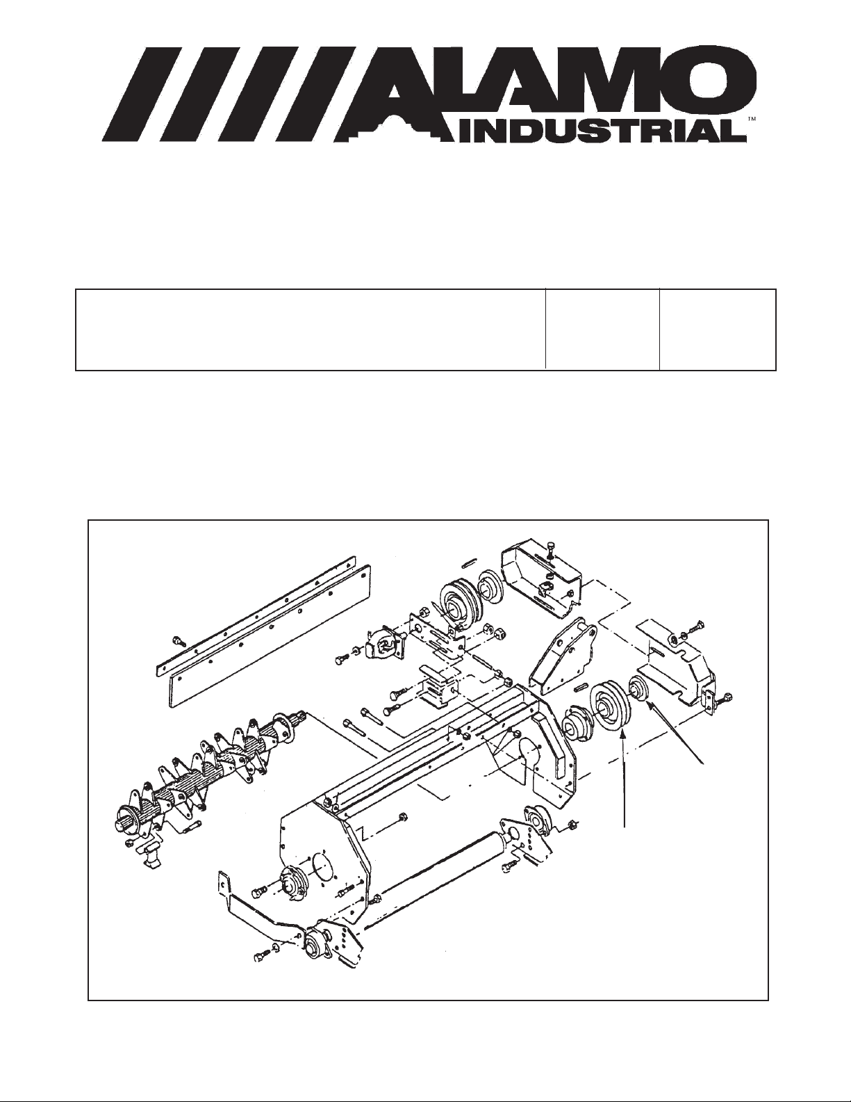
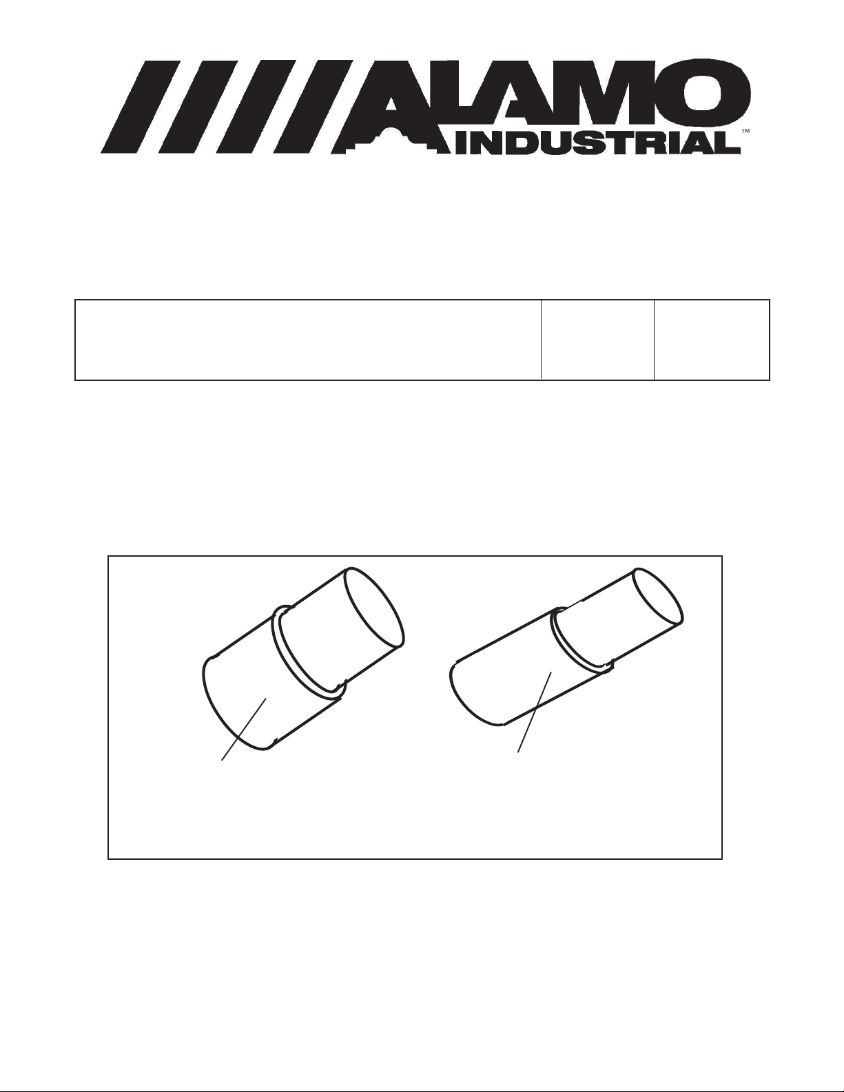
Pulley Fastening to Cutter Shaft of Flail Axe Head:
Subject:
A new method has been devised to secure the pulley to the cuttershaft. A new pulley, P/N
02968712 and a QD Pulley Hub P/N 00724670 has replaced the old pulley with setscrew, washer,
lockwasher and bolt. The new pulley and hub are a keyed, taper lock design which will provide a better
fit and longer service life for the shaft.
Hub P/N
00724670
Pulley P/N
02968712
Figure 1
This document does not authorize the repair or replacement of parts under warranty
MACHETE
© 2005 Alamo Group Inc.
1-2
Page 9

NOTES
MACHETE
© 2005 Alamo Group Inc.
1-3
Page 10

TECHNICAL INFORMATION BULLETIN No. 092895
Alamo Industrial Technical Services Department
1502 East Walnut
Seguin, Texas 78155
830-372-2708
Models:
All Hydraulic mowers using the 02964028 Push-Pull Switch
Bulletin No:
092895
Date:
Sep. 28, 1995
Failures of the mower push-pull switch:
Alamo has recently received reports of failures of the referenced switch. The failures
modes are:
(a) Knob pulls off rod.
(b) Rod and Knob pulls out of switch body.
Test performed on numerous switches indicates that the (b) failures are due to excessive
force being applied to the knob when shutting off the mower. Specifically, the knobs are usually
roughly slapped to turn the mower off. After internal parts of the switch are damaged, the rod can
then be pulled out easily. The (a) failures are due to the knobs not being securely tightened.
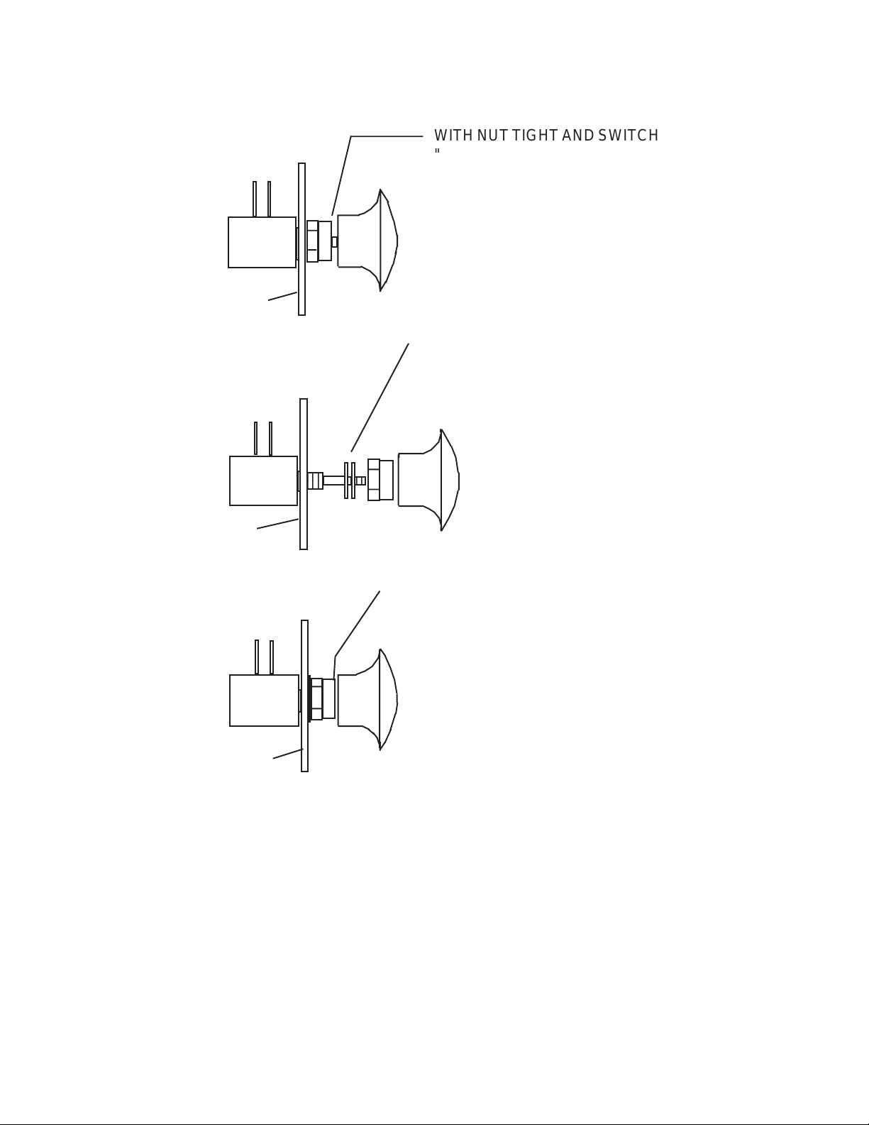
To prevent these failures from occurring, or to replace a damaged switch, use the following
procedure to adjust the travel of the switch. (See attached diagram).
1. Install the switch body in the holder and tighten the nut.
2. Screw the Knob on the rod to the bottom of the thread, but do not overtighten. It
will probably be necessary to hold the rod with pliers to get the knob tight, if you do
use caution not to score the rod with the pliers.
3. Measure the distance (if any) between the knob and the nut. Record the
measurement.
4. If a Gap exists between the knob and the nut, remove the knob.
5. Remove the nut and install the same thickness of flat washers that was
measured in step 3. Install and tighten the nut> DO NOT install more washers
than needed to take up the space. Flat Washer Part No. 00023500 or equivalent can
be used.
6. Install the Knob, using Locktite or similar thread locking compound. Thread the
knob on the rod all the way. Test to make sure that when the switch is "Off" (with
rod pushed in) that the knob can not travel further into the switch.
MACHETE
© 2005 Alamo Group Inc.
Continued Next Page
1-4
Page 11
Information Bulletin 092895 Continued from previous Page
4
4
WITH NUT TIGHT AND SWITCH
"OFF". MEASURE THIS GAP IF ANY
MOUNT PLATE
IF GAP EXIST, INSTALL WASHERS OR
SHIMS TO EQUAL GAP MEASURED IN
STEP 3
23
23
MOUNT PLATE
KNOB SHOULD LIGHTLY CONTACT
NUT WHEN PROPERLY ADJUSTED
MOUNT PLATE
TECHNICAL INFORMATION BULLETIN
No. 092895
Contact:
Alamo Industrial
Technical Services Department
1502 East Walnut
Seguin, Texas 78155
Ph; 830-372-2708 Fax; 830-372-9603
This document does not authorize the repair or replacement of parts under warranty
MACHETE
© 2005 Alamo Group Inc.
1-5
Page 12
TECHNICAL INFORMATION BULLETIN No. 121495
Alamo Industrial Technical Services Department
1502 East Walnut
Seguin, Texas 78155
830-372-2708
Models:
Machete Boom Axe, Versa Boom, A-Boom, Slopemower
& Rear Mount Booms.
Repair Procedure for Welding Cracks in Boom Heads:
A
A
A
If cracks appear in the welds at points "A" as shown above, use the following procedures to
repair head.
Bulletin No:
121495
A
A
A
Date:
Dec. 14, 1995
Parts Needed:
Part No. Qty Description
02970111 2 90° Gusset
02970112 4 48° Gusset
Welding Procedure:
1. Grind a groove at the site of the crack and clean the area to be welded.
2. Weld the crack making a 100% weld.
3. After repairing the cracks, prepare the sites for installation of the gussets.
4. Position the reinforcing bar gusset part no. 02970111 if 90° or part no. 02970112 if 48° over
the X-Bar as shown in drawing next page. Weld with a 1/4" fillet weld on the bottom and an
edge weld on top. DO NOT weld the ends.
5. Clean and paint the area.
6. Reassemble any parts that were removed.
Continued Next Page
MACHETE
© 2005 Alamo Group Inc.
1-6
Page 13
Information Bulletin 121495 Continued from previous Page
48° Gusset
1/4"
1/4"
90° Gusset
Note; Do Not weld ends
1/4"
1/4"
TECHNICAL INFORMATION BULLETIN
No. 121495
Contact:
Alamo Industrial
Technical Services Department
1502 East Walnut
Seguin, Texas 78155
Ph; 830-372-2708 Fax; 830-372-9603
This document does not authorize the repair or replacement of parts under warranty
MACHETE
© 2005 Alamo Group Inc.
1-7
Page 14
TECHNICAL INFORMATION BULLETIN No. 010896
Alamo Industrial ™ Technical Services Department
1502 East Walnut
Seguin, Texas 78155
830-372-2708
Models: All Machete Boom Mowers
Bulletin No:
010896
Date:
Jan. 8, 1996
Trouble shooting improper operation of motor starting circuit:
The correct operation of the motor is for the operator to pull out the Main Motor Switch and
then momentarily press the Motor Start Button. the Motor will advance to full operating speed and will
continue to run while the Main Motor Switch is in the OUT position.
If the harness is wired wrong, the motor will start as soon as the Motor Start Switch is pulled
out without pressing the Motor Start Button.
A
C
Pull
Circuit
B
Hold
Circuit
The above illustration is the female connector of the motor wire harness
Corrective Action:
Using needle nosed pliers, push the B and C connectors out of the back of the plug and
reinstall them in the opposite positions, or cut the two wires to the B and C connectors and splice
them back together reversing them.
This document does not authorize the repair or replacement of parts under warranty
MACHETE
© 2005 Alamo Group Inc.
1-8
Page 15
TECHNICAL INFORMATION BULLETIN No. 020596
Alamo Industrial ™ Technical Services Department
1502 East Walnut
Seguin, Texas 78155
830-372-2708
Models: Machete Boom Mowers MB21 & MB24
Bulletin No:
020596
Date:
Feb. 5, 1996
New Piston Pump used on Machete:
A new Pump is being used on all Machete Boom Mowers. The new pump utilizes a solenoid
valve and manifold (New Parts) to control pump swashplate movement instead of the former (Old
Parts) electric solenoid, Spool valve and adjustable linkage. All other parts of the pump remain the
same. The new parts provide for more positive trouble free operation of the pump and do not require
adjustment.
There will be a harness adapter required to connect the new two wire connector to the old
three wire harness. Adapter and instructions are included in replacement parts. When the former (old
part number is ordered, all the new parts will be provided.
New Parts
Old Parts
Former Part No. Description Replacing Part No.s Description
02967192 Pump Assembly 02969527 Pump Assembly
02970201 Decal, Joystick
02970205 Adapter, Wire Harness
02970224 Insert, Instruction Sheet
This document does not authorize the repair or replacement of parts under warranty
MACHETE
© 2005 Alamo Group Inc.
1-9
Page 16

TECHNICAL INFORMATION BULLETIN No. 032596
Alamo Industrial Technical Services Department
1502 East Walnut
Seguin, Texas 78155
830-372-2708
Models: Machete Boom MB21 & MB24
Bulletin No:
032596
Date:
Mar. 25, 1996
New Seal Protector Added to Blade Bar Assembly:
A few machines have experienced operational problems such as failure of the blade bar to rotate
when the mower is engaged or a slight loss of power at the blades. Sometimes it is assumed that the
spindle has seized and the spindle is replaced without investigating further.
The problem is usually found to be that the spindle end cap cover is binding on the spindle
housing, creating sufficient drag on the shaft to result in the symptoms described above. This condition
is a result of material (Vines, Wire, etc.) wrapping around the cover and forcing it to contact and drag
against the spindle housing, causing no damage to internal components of the spindle.
A new seal protector has been designed to aid in preventing material from wrapping around the
seal cover area. While nothing can completely prevent material from getting to the seal cover, the new
seal protector should greatly reduce the probability of spindle seizures due to these causes.
If a machine is operating or is going to operate in an application in which material is likely to wrap
around spindle, the following parts can be ordered and installed. The old seal protector (# 02968868)
which is on the spindle will be removed and discarded. The Old Part No. 02968868 will be ordered but
the new Seal Protector Part No. 02970459 will be shipped with installation instructions. If only the new
Seal protector is ordered the instruction sheet will not be shipped.
Part No. Qty Description
02968868 1 Cover, End Cap (Seal Protector)
The new seal protector will have to be welded to the upper blade bar as shown on the next page
and the old seal protector which is on the spindle will be discarded. Make sure that the Blade bar
retaining bolts are properly torqued when reattaching to spindle and that components are good
condition.
Continued Next Page
MACHETE
© 2005 Alamo Group Inc.
1-10
Page 17
Information Bulletin 032596 Continued from previous Page
Weld 4 places
3/16"
Seal Protector Ring
# 02970459
1" long
Note: Center ring on blade bar
to allow clearence for spindle.
Blade Bar Asy
# 02782300
Old Seal Protector,
# 02968868 Cover,
End Cap is
no longer used
TECHNICAL INFORMATION BULLETIN
No. 032596
Contact:
Alamo Industrial
Technical Services Department
1502 East Walnut
Seguin, Texas 78155
Ph; 830-372-2708 Fax; 830-372-9603
This document does not authorize the repair or replacement of parts under warranty
MACHETE
© 2005 Alamo Group Inc.
1-11
Page 18

TECHNICAL INFORMATION BULLETIN No. 040896
Alamo Industrial ™ Technical Services Department
1502 East Walnut
Seguin, Texas 78155
830-372-2708
Models: All Models using Single Acting Hydraulic Cylinder
Bulletin No:
040896
Date:
Apr. 8, 1996
Oil Leaking from new single Acting Hydraulic Cylinders:
There have been numerous cases of the dealers and customers replacing single acting
hydraulic cylinders on new machines due to oil leakage out of the vent plug in the cylinder.
In many of these instances, no defect could be found in the cylinders. Further investigation
has revealed that he manufacture of our cylinders is leaving oil in the cylinders after their testing. The
Oil is left to help protect the interior of the cylinders during storage. When the cylinders are fully
actuated, they are forcing this oil out the vent plug, causing what appears to be a leaking cylinder
through the vent plug. Even the oil is cleaned off the cylinder after testing there is enough oil still inside
the cylinder to bleed out when used.
If you have a New Cylinder that appears to be leaking from the vent plug, The oil should be
cleaned off and unit ran for a few days to a week to determine if the Cylinder is leaking, or if it is the
oil that was left in the cylinder to protect it. It has been found that in some cases it has taken as much
as a week for this to appear that it is not leaking.
If after running and cycling the cylinder during operation and the cylinder continues to leak then
the necessary repair should be performed.
Cylinders that are attracting dust around them is not considered to be leaking. This dust
collecting around them is considered normal.
All Cylinder that are returned as leaking will be pressure tested for leakage to determine the
condition of the Cylinder and its components.
This document does not authorize the repair or replacement of parts under warranty
MACHETE
© 2005 Alamo Group Inc.
1-12
Page 19
TECHNICAL INFORMATION BULLETIN No. 042996
Alamo Industrial ™ Technical Services Department
1502 East Walnut
Seguin, Texas 78155
830-372-2708
Models: All New Holland Tractors with Alamo Industrial Mounted
Booms
Bulletin No:
042996
Date:
Apr. 29, 1996
Dead Batteries on New tractors:
There have been several reports recently of dealers receiving machines with dead batteries,
some of which could not be satisfactorily recharged. Please see the attached copy of a tag which
is coming with the new tractors.
The "small electrical discharge" being mentioned amounts to a constant drain on the battery.
If the battery cable (+ Post) is left connected for a long enough time with the tractor inactive, the battery
will become sulfated (permanently damaged) and will not accept a charge. Sulfated batteries are not
warranted through the battery manufacturer.
At present, the only alternative to removing the battery cable would to be install a battery
disconnect switch in the negative cable, which would allow the battery to be easily isolated. These
switches are available at most major tractor dealers. USE CAUTION when installing any thing on
battery cables, disconnect the positive cable before installing disconnect switch and make sure after
switch is installed that it is "OFF" before reconnecting Positive Cable.
ATTENTION ! BATTERY CARE
Your new Tractor has electronics which cause a very small electrical demand on the battery. If the
tractor in not in use for an extended period, disconnect battery to avoid damage by excessive discharge.
Recharge Battery if voltage is less than 12.3V (S.G. less than 1.140)
Lataa Akku uudelleen, jos jannite on alle 12.3V (ominaispaino alle 1.140)
Ricaricare la batteria se il voltaggio e inferiore a 12.3V (G.S. inferiore a 1.140)
Batteria recarregavel se a voltagem for inferior a 12.3V (Gravidade especifca inferior a 1.140)
Laddt de batterijweer op wanneer de voltage lager is dan 12.3V (S.G. Minder dan 1.140)
Recharger la batterie si la tension est inferieure a 12.3V (Densite inferieure a 1.140)
Batterie wieder aufladen. wenn spanning unter 12.3V (Spez gewicht unter 1.1.40 IST)
Recarcar la bateria si el voltage es inferior a 12.3V (S.G. inferior a 1.1.40)
Batteriet ma lades opp hvis spenningen er mindre enn 12.3V (Spesifikk vekt under 1.1.40)
_
+
Part No. 82001815
This document does not authorize the repair or replacement of parts under warranty
MACHETE
© 2005 Alamo Group Inc.
1-13
Page 20
TECHNICAL INFORMATION BULLETIN No. 010397
Alamo Industrial Technical Services Department
1502 East Walnut
Seguin, Texas 78155
830-372-2708
Models: Machete Boom MB21 & MB24
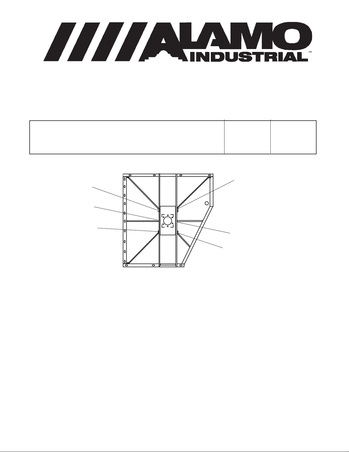
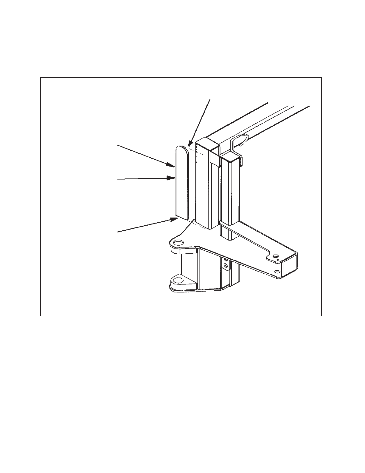
Cracks in Main Frame:
There have been some cracks
in the main frame of some machete
mowers
If a crack should develop (See
Figure 1), use the following procedure to
make repairs untill a permanent repair is
developed. NOTE: This repair will aloow
the machine to continue operating while
a long term correction for the problem is
being developed.
1. Grind out old weld (crack) and
weld the crack, Do not use an excessive high repair weld as you will need to
grind repair weld down smooth.
Crack
develops
here
Figure 1
Bulletin No:
010397
Date:
Jan. 3, 1997
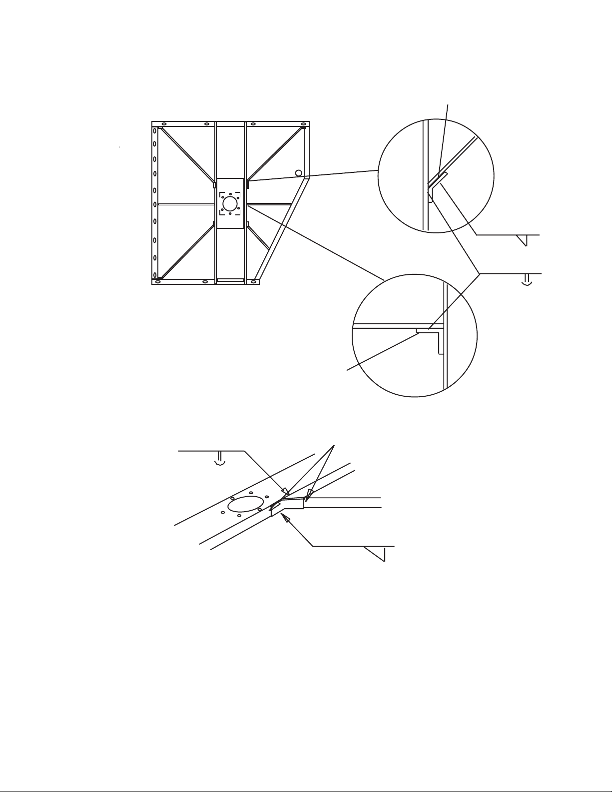
2. Prepare a piece of 1/2" X 6"
HRFB cut to length (See Figure 2). The
bottom should rest against the King
Post frame and the top should be with in
2" of the top of the frame, this will
determine the height of the repair plate
(See Figure 3). Bevel the bottom side of
the plate that is towards the frame to
allow for the old weld. This will be evedent
if you test fit the repair plate.
3. Place the stiffener repair plate
against the vertical memeber of frame
(as shown in figure 3) and tack weld into
position, Make sure repair plate is flat
against the frame.
MACHETE
© 2005 Alamo Group Inc.
Taper the Top
Bevel the side
towards frame to
clear old weld
Figure 2
Continued Next Page
1-14
Page 21
Information Bulletin 010397 Continued from previous Page
4. Weld the plate as described in figure 3
5. After welding is complete, clean weld and immeadiate area . Paint the are around the repair
and areound any area where the paint was damaged from making this repair.
1/4" fillet weld across the top
Stiffener plate 1/2" X 6" HRFB,
cut to fit as shown
Skip weld up sides
1/4" fillet weld across
bottom and sides
Figure 3
TECHNICAL INFORMATION BULLETIN
No. 010397
Contact:
Alamo Industrial
Technical Services Department
1502 East Walnut
Seguin, Texas 78155
Ph; 830-372-2708 Fax; 830-372-9603
This document does not authorize the repair or replacement of parts under warranty
MACHETE
© 2005 Alamo Group Inc.
1-15
Page 22
TECHNICAL INFORMATION BULLETIN No. 012097
Alamo Industrial ™ Technical Services Department
1502 East Walnut
Seguin, Texas 78155
830-372-2708
Models: Machete, MB21 & MB24
Bulletin No:
012097
Date:
Jan. 20, 1997
Interference between Tube Clamps and Main Frame:
It is possible that the boom hydraulic tube clamps may contact the main frame when boom
is raised to its highest position. This condition effects only machines with certain frames. If you have
a machine that has this interference problem use the procedures described in this bulletin to correct
the problem. (See Figure 1).
25"
To prevent interference of the
hydraulic pipe clamps with the
frame move the clamps to this
new 25" distance
Figure 1
If the parts on your unit are damaged, loosen the six bolts that hold the three tubes. Cut the
bracket away from the boom. Relocate the bracket on the boom so it clears the frame. Weld in place
and paint. Tighten the six bolts. Total time to perform this modification will be approximately 1.5 hours
time or less. If parts are required there is a kit that can be installed, the Kit # 02971938.
This document does not authorize the repair or replacement of parts under warranty
MACHETE
© 2005 Alamo Group Inc.
1-16
Page 23
TECHNICAL INFORMATION BULLETIN No. 031097
Alamo Industrial ™ Technical Services Department
1502 East Walnut
Seguin, Texas 78155
830-372-2708
Models: Machete, MB21 & MB24
&
Brahma Side Mount models
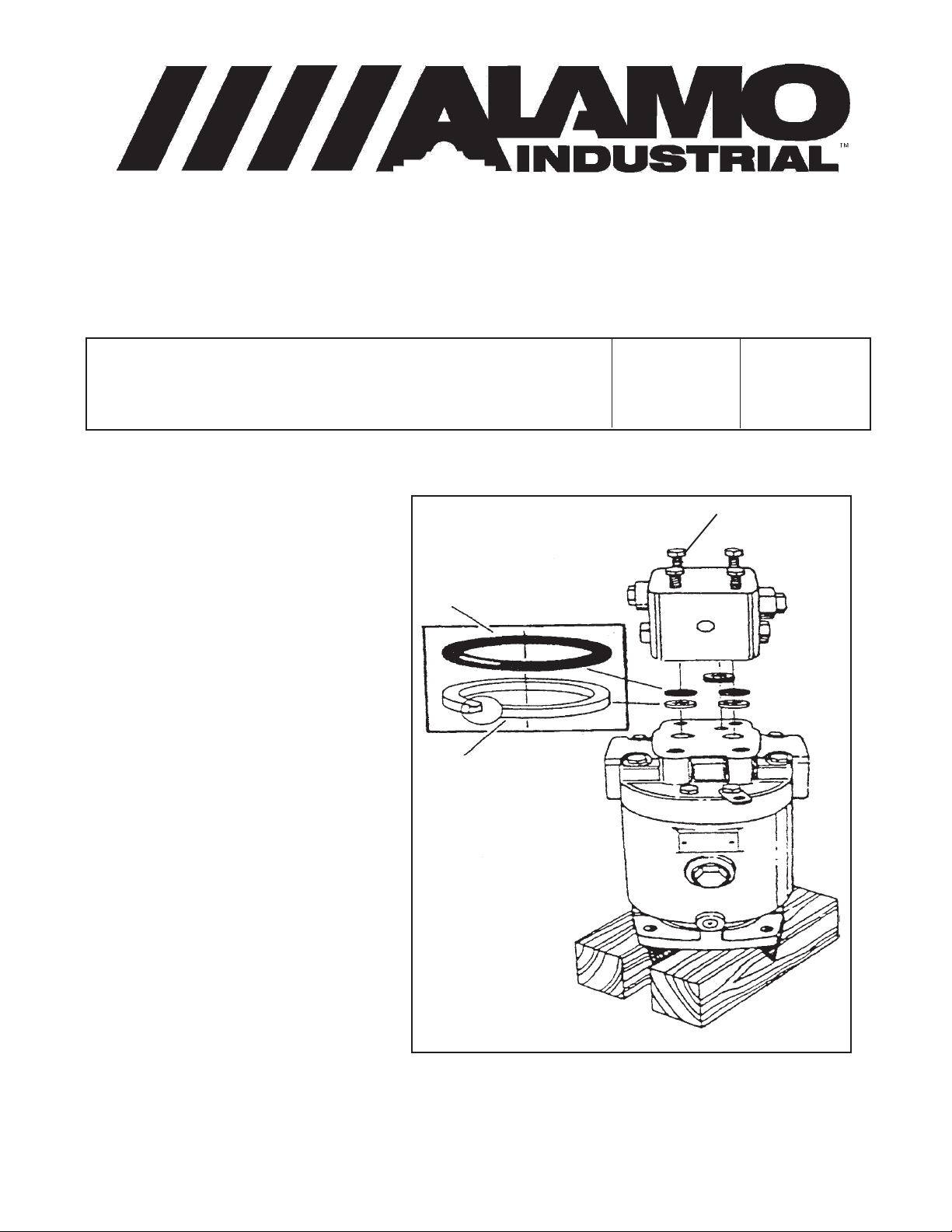
Valve Block O-Ring Replacement Kit available:
A kit (Kit # 02972094) to replace
the O-Ring and Back-up Rings which
are located between the valve block and
the motor housing on the piston motors
# 02977193 used on the Brahma rotary
and Machete boom mounted cutters is
available. The Valve block must be removed when the motor is replaced as it
is attached to the support plate. This
causes an occasional failure of the seals.
Install O-Rings and Back-up
Rings on the valve block. The High Pressure Ports require an O-Ring and Backup Ring. The O-Ring goes on first
(against valve block) , then the Back-up
ring (against motor) as shown (See
Figure 1). Install the Square-Cut Ring in
the Low Pressure Drain Port of the
valve block.
O-Ring
Back-up Ring
Bulletin No:
031097
Date:
Mar. 10, 1997
Valve Block
Retaining Bolts
When installing the valve block
the retaining bolts to the motor they
must be torqued to 35 ft. lbs. in an
alternating pattern.
Figure 1
This document does not authorize the repair or replacement of parts under warranty
MACHETE
© 2005 Alamo Group Inc.
1-17
Page 24
TECHNICAL INFORMATION BULLETIN No. 032697
Alamo Industrial ™ Technical Services Department
1502 East Walnut
Seguin, Texas 78155
830-372-2708
Models: Machete, MB21 & MB24
Bulletin No:
032697
Date:
Mar. 26, 1997
King Pin and Boom Pin Bushing Drivers Available:
It is now possible to obtain the proper bushing driver to facilitate the installation of all bushings
on the Machete Boom Assembly. The Large Driver (P/N 02972281) is used to install the King Pin
Bushings in the frame, while the Small Driver (P/N 02972282) should be used to install all the
bushings in the boom. These tools may be used to install bushings on several other Alamo Industrial
Models such as Slope Mowera and A-Booms. The proper use of the installation tools will help to
prevent damage to the bushing surfaces during installation.
# 02972281 for driving
2-1/2" ID Bushings
# 02972282 for driving
1-1/2" ID Bushings
Figure 1
Note: Replaces / Same as Bulletin No. 032697A
This document does not authorize the repair or replacement of parts under warranty
MACHETE
© 2005 Alamo Group Inc.
1-18
Page 25

NOTES
MACHETE
© 2005 Alamo Group Inc.
1-19
Page 26
TECHNICAL INFORMATION BULLETIN No. 041797-1
Alamo Industrial ™ Technical Services Department
1502 East Walnut
Seguin, Texas 78155
830-372-2708
Models: Machete, MB21 & MB24
Bulletin No:
041797-1
Date:
Apr. 17, 1997
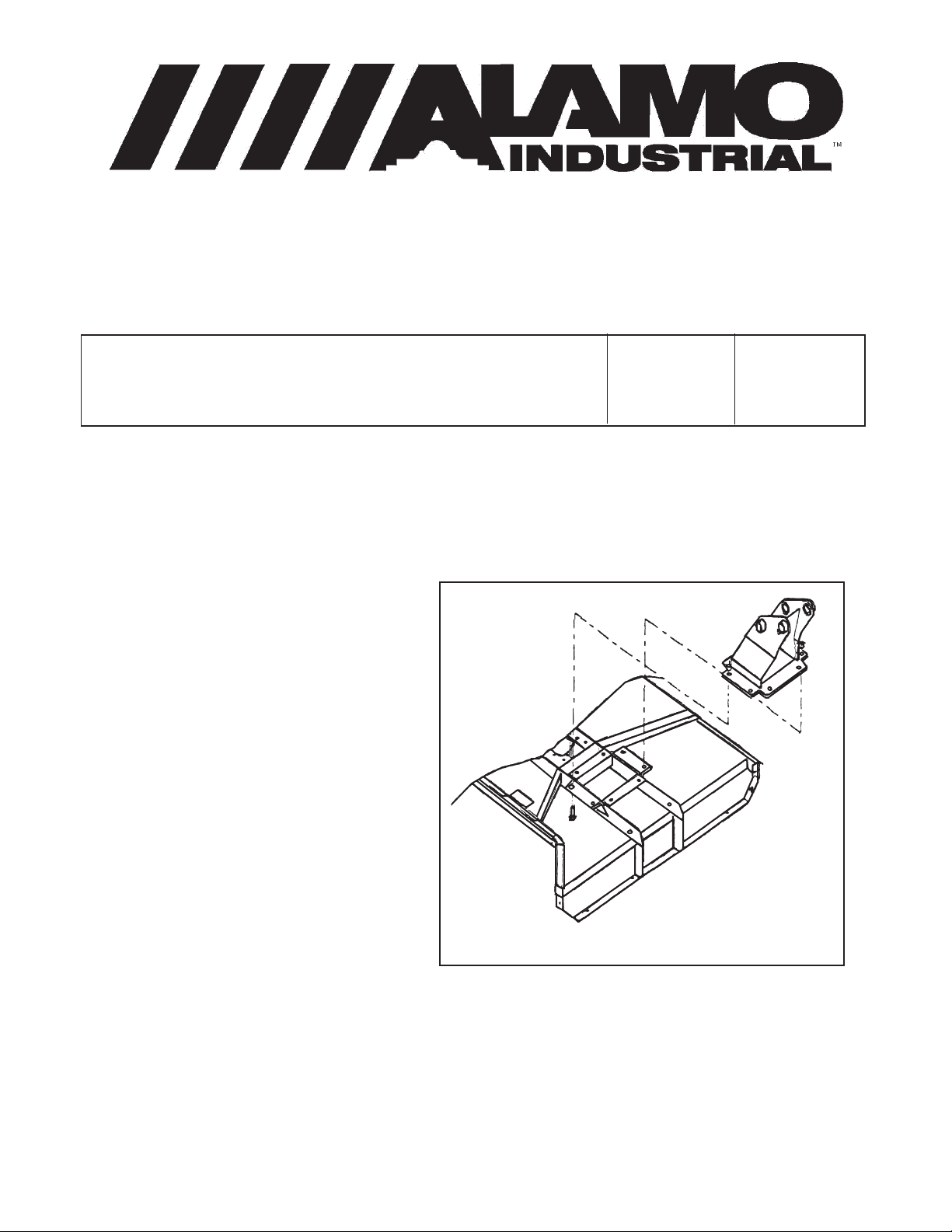
Hitch Post Replacement Kits:
Hitch Post replacement kits are now available for Machete Boom models MB21 & MB24. The
new design utilizes an 8 bolt flange design which requires angle braces to be welded to the cutter
head. If you are experiencing problems with the original hitch post, it could be replaced with the new
design. Install the new Hitch Post using the following procedure.
Important ! Any warranty repairs must be done in accordance with warranty policy and
service bulletin SB No. 970002A only.
Hitch Post Replacement Kits:
(Qty use 1 each)
Part No. Description
02972231 Hitch Post Kit
02967691 Pin Kit
02967687 Pin Kit
02972232 Instruction Sheet
Note: Instruction Sheet is included in Kit.
Repair Procedures:
1. Remove Head from Boom by follow-
ing cutting head removal & install instructions in the Operators Parts manual. If you do
not have this manual it is recommended you
obtain one before proceeding with this repair.
Figure 1
New 8 Bolt Flange
Hitch Post and Deck
Shown
2. Remove the old Hitch Post from the head. Clean all debris and Oil off of deck. Clean the paint
off around the area where the new flange will be welded.
3. Place angles (02971946 & 02972111) on rotary head as shown in Figure 2 and Figure 3. All
measurements are to be taken from the edge of the 3/8" X 3" ribs running across the rotary head.
Continued Next Page
MACHETE
© 2005 Alamo Group Inc.
1-20
Page 27
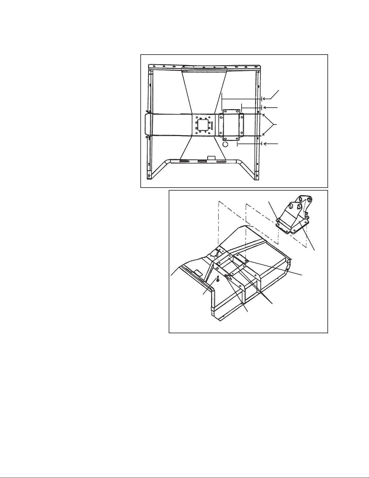
Information Bulletin 041797-1 Continued from previous Page
4. After aligning the Angles to Deck (See Figure 2) tack weld them in place. Recheck all
measurements and alignments, then weld in flanges in place.
5. Clean all welds and area
around welds, remove weld
slag, burnt paint and etc. Repaint complete area around
flanges to prevent rust.
24-1/16" center
of hole to edge
6.
(02971928) to welded angles as
shown in Figure 3 using hardware furnished with kit. Install the
Lock nut on top of the Hitch post
and the bolt heads down coming
up through the flanges, this will
give the maximum strength to the
bolts and Hitch components.
7. Reinstall Head to Boom
by following cutting head removal & install
instructions in the Operators Parts manual.
If you do not have this manual it is recommended you obtain one before proceeding
with the reinstall of head.
Hitch Post Kit # 02972231 includes -
Part No. Qty Description
02971928 1 Hitch Post
02972111 2 Angle
02971946 2 Angle
02892100 8 Bolt
00037200 8 Locknut
02972232 1 Instruction Sheet
Pin Kit # 02967691 includes -
02971756 1 Pin, Chrome
02971746 1 Bushing
02970595 1 Bolt
00015800 1 Locknut
02971904 1 Instruction Sheet
Pin Kit # 02967687 includes -
02971720 1 Pin Weldment
02971701 1 Nut, Slotted
02971702 1 Flat Washer
165020 1 Cotter Pin
Attach new Hitch Post
Figure 2
00037200 Nut (8)
02892100
Bolt (8)
Figure 3
02971946
Flange (1)
02972111
Flange (2)
Note: Replaces / Same as Bulletin
No. 041797A1
12-1/16" center
of hole to edge
Reference Ribs
14--9/16" center
of hole to edge
02971928
Hitch Post (1)
02971946
Flange (1)
TECHNICAL INFORMATION BULLETIN
No. 041797-1
This document does not authorize the repair or replacement of parts under warranty
MACHETE
© 2005 Alamo Group Inc.
1-21
Page 28

TECHNICAL INFORMATION BULLETIN No. 041797-2
Alamo Industrial ™ Technical Services Department
1502 East Walnut
Seguin, Texas 78155
830-372-2708
Models: Machete, MB21 & MB24
Bulletin No:
041797-2
Date:
Apr. 17, 1997
Cylinder & Linkage Pin Replacement Kits:
Boom cylinder pin replacement kits for all Machete MB21 & MB24 mowers are now available.
The new design utilizes a Boss and Bolt arrangement to replace the original tear drop and bolt design.
Each kit contains all the necessary parts along with a detailed instruction sheet regarding the correct
replacement procedure for the pins. Likewise, if new pins are ordered in the future, the original part
numbers will be automatically replaced with the new design being shipped to you. Welding and painting
will be required.
If you are experiencing problems with the original pin design. Order the new kit and replace the
pins with the new design. Instruction Sheet # 02971904 will be sent with each kit ordered. This
instruction sheet will show detailed instructions on how to install the following kits.
If replacing these as warranty, follow all warranty procedures in accordance with warranty
guide and Service Bulletins which apply to this application only.
Kit Numbers:
Kit No. Q tyDescription Kit No. Q t y Description
02967685 1 Pin Kit, Dipper Cyl. Rod End 02967691 2 Pin Kit, Head Tilt Linkage
02967673 1 Pin Kit, Swing Cyl. Barrel End 02967694 1 Pin Kit, Tilt Cyl. Rod End
02967677* 1 Pin Kit, Lift Cyl. Rod End 02967683 1 Pin Kit, Tilt Cyl. Barrel End
02967677* 1 Pin Kit, Dipper Cyl. Barrel End 02967675 1 Pin Kit, Swing Cyl. Rod End
02967679 1 Pin Kit, Lift Cyl. Barrel End
02967681 1 Pin Kit, Link Arm to Dipper
02967694 1 Pin Kit, Link Arm to Linkage
02966791 1 Pin Kit, Linkage Asy to Hitch Post.
02868803 a/r Pin Bushing
Note: there is also a Turning Arm Upgrade Kit which
includes a new 1 piece king pin, All Bushings and
Turning arm (Kit # 02972211) which is not shown
here.
Bolt & Nut
New
Pin
Weld on Boss
Figure 1
Continued Next Page
MACHETE
© 2005 Alamo Group Inc.
1-22
Page 29

Information Bulletin 041797-2 Continued from previous Page
Weld
Weld
Weld
Weld
Weld
Weld
Weld
Figure 2
Note: Replaces / Same as Bulletin No. 041797A2
TECHNICAL INFORMATION BULLETIN
No. 041797-2
This document does not authorize the repair or replacement of parts under warranty
MACHETE
© 2005 Alamo Group Inc.
1-23
Page 30

TECHNICAL INFORMATION BULLETIN No. 060197
Alamo Industrial ™ Technical Services Department
1502 East Walnut
Seguin, Texas 78155
830-372-2708
Models: Machete, MB21 & MB24
Bulletin No:
060197
Date:
Jun. 1, 1997
Tilt Link Arm Stop:
Some Machete models may exhibit interference between the head tilt cylinder and the cutter
motor support plate. This can result in a bent head tilt cylinder rod, a damaged cylinder gland cap, or
a damaged cutter motor housing.
In order to avoid possible damage, a stop should be fabricated and installed which will limit the
head tilt retraction before interference occurs.
A stop made from 1/2" X 2-1/4" HRFB X 6-1/2" long should be welded to head tilt link arm
weldment as shown in figure 1. This will require welding and painting.
To locate the proper angle position of the new stop, carefully retract the head until the cutter
motor support plate and the head tilt cylinder has a clearance of 1". Use caution, do not damage cylinder
when retracting the head. Place the new stop plate in the head tilt link weldment and lay it flat on the
dipper arm. Mark this position, and weld the stop in place as shown in Figure 1. It is important that the
stop is installed so that it flatly contacts the dipper when retracted in order to avoid point loading on the
boom. Extend and retract the cylinder to ensure proper installation.
Existing Formed Gusset
1/4" Weld
Existing Formed Stop
Figure 1
Do Not Weld
on this side
New Stop
Position the New Stop
so that it contacts the
existing Formed
Gusset
Note: Replaces / Same as Bulletin No. 060197A
This document does not authorize the repair or replacement of parts under warranty
MACHETE
© 2005 Alamo Group Inc.
1-24
Page 31

TECHNICAL INFORMATION BULLETIN No. 061897
Alamo Industrial ™ Technical Services Department
1502 East Walnut
Seguin, Texas 78155
830-372-2708
Models: Machete, MB21 S/N 01001 - 01071, 03507 & 02684
& MB24 S/N 01001 - 01040 & 03459
Bulletin No:
061897
Date:
Jun. 18, 1997
New Thick Blade Bar & Larger Bolts:
Early October 1996, in order to ensure an extended service life, a new blade bar was introduced
which featured larger blade bar leaf bolts (from 7/8" to 1-1/4") and a thicker bottom leaf. As a result,
longer mounting bolts (from 3-1/2" to 4") are required to ensure adequate thread engagement into the
spindle shaft.
When ordering a replacement blade bar using the original number, the new blade bar design
will automatically be sent. However, the 4 longer mounting bolts may not be included.
Therefore, when ordering a replacement blade bar, ensure that the proper length mounting
bolts (P/N 02964861 which is a 4" Bolt) are also replaced. DO NOT attempt to mount the new style blade
bar using the old shorter bolts. The best way is to always check the replacement bottom leaf thickness
as compared to the bottom leaf that was removed. If the replacement is thicker then the new longer
bolts will be needed. Another way to determine which one you have check the Leaf retaining bolt size.
Blade Leaf Bar Bolts (Torque
1-1/4" bolts to 2000 ft. lbs.)
Blade Bar Mounting Bolts
(Torque to 400 ft lbs.)
Figure 1
Note: Replaces / Same as Bulletin No. 061897A
This document does not authorize the repair or replacement of parts under warranty
MACHETE
© 2005 Alamo Group Inc.
1-25
Page 32

TECHNICAL INFORMATION BULLETIN No. 071797
Alamo Industrial ™ Technical Services Department
1502 East Walnut
Seguin, Texas 78155
830-372-2708
Models: Machete, MB21 S/N 01001 - 01108
& MB24 S/N 01001 - 01045
Bulletin No:
071797
Date:
Jul. 17, 1997
Joystick Power Cut Off Switch:
A Joystick Supply Cut Off Switch (Master Switch) can be added to the Machete in order to
eliminate the possibility of damage caused by the joystick moving while roading the machine over rough
terrain. Inadvertent movement of the controller can result in uncontrolled movement of the boom which
may result in damage to the boom rest, the tractor or other areas.
Parts needed:
Part No. Qty Description
02964028 1 Push Pull Switch, (or a locally purchased switch)
------------- 2 12 or 14 gauge wire butt connectors (furnished by installer)
------------- a/r 14 gauge wire cut to length, preferably red wire (furnished by installer)
Procedure:
1. Turn off the tractor ignition and remove the key (disable tractor to where it can only be started
when you want it started). Set parking Brake.
2. Find the RED Voltage supply wire which supplies electrical power to the Joystick.
3. Locate a suitable mounting position within easy reach of the operator, and run the two wires
from the new switch to the red power supply wire. Cutting the existing power supply wire connect the
two butt connector from the switch to the cut power supply, see drawing.
4. Operate the machine to ensure that the joystick functions will not work when switch is "OFF"
and will when switch is "ON"
Hook terminal Connector
Butt connectors to tractor starter solenoid
Master Switch
Swing
Lift
Ground (Black)
Tractor starter solenoid (brown)
Joystick connector Plug
Dipper
Switched Voltage
Tilt
Door
Butt
connectors
2 pin connector for pump solenoid
Supply (Red)
Note: Replaces / Same as Bulletin No. 071797A
This document does not authorize the repair or replacement of parts under warranty
MACHETE
© 2005 Alamo Group Inc.
1-26
Page 33

TECHNICAL INFORMATION BULLETIN No. 100397
Alamo Industrial ™ Technical Services Department
1502 East Walnut
Seguin, Texas 78155
830-372-2708
Models: Machete, MB21 S/N 01001 - 01108
& MB24 S/N 01001 - 01045
Bulletin No:
100397
Date:
Oct. 3, 1997
Cylinder, Link Arm, Turning Arm & Hitch Post Pin Update Kit:
Parts Required to update a Machete Boom Mower to the current Pin Design. In an effort to
remedy some of the confusion which exists in regards to what is required to update the Machete Boom
Mowers, the following list has been prepared. If all the listed parts are installed in accordance with the
related Service and Technical Bulletins, along with the instructions provided with each individual kit. The
mower will be updated to the way the current models are built.
Parts Required:
(Main Pin Replacement Kit, See Service Bulletin No. 970002A)
Part No. Qty Description Part No. Qty Description
02967689 1 Pin Kit, Main Pin at Turning Arm 02967693 1 Pin Kit, Dipper to Lift Arm
02967687 1 Pin Kit, Dipper to Hitch Post
(Cylinder Pin Kits, See Technical Information Bulletin No. 041797-2)
Part No. Qty Description Part No. Qty Description
02967679 1 Pin Kit, Lift Cyl. Barrel End 02967677* 1 Pin Kit, Lift Cyl. Rod End
02967683 1 Pin Kit, Tilt Cyl. Barrel End 02967681 1 Pin Kit, Tilt Cyl. Rod End
02967677* 1 Pin Kit, Dipper Cyl. Barrel End 02967685 1 Pin Kit, Dipper Cyl. Rod End
02967679 1 Pin Kit, Swing Cyl. Barrel End 02967675 1 Pin Kit, Swing Cyl. Rod End
02967681 1 Pin Kit, Hitch Post Link Arm to Dipper
02967694 1 Pin Kit, Hitch Post Link Arm to Linkage Asy.
02967691 1 Pin Kit, Linkage Asy. to Hitch Post
02968803 10 Pin Bushing
(Mower Head Hitch Post Replacement Kit, See Technical Information Bulletin No. 041797-1)
Part No. Qty Description
02972231 1 Hitch Post Replacement Kit
(Turning Arm - King Pin Replacement Kit, See Service Bulletin No. 970008A)
Part No. Qty Description
02972211 1 Turning Arm - King Post Replacement Kit
(Lift, Dipper and Head Tilt Drop Restrictions See Service Bulletin No. 970004A & 960009)
Part No. Qty Description Part No. Qty Description
02972159 3 Straight Adapters 02969398 3 .055" Orifice Plates
This document does not authorize the repair or replacement of parts under warranty
MACHETE
© 2005 Alamo Group Inc.
1-27
Page 34

TECHNICAL INFORMATION BULLETIN No. 112097
Alamo Industrial ™ Technical Services Department
1502 East Walnut
Seguin, Texas 78155
830-372-2708
Models: Machete, MB21 S/N 01001 - 01108
& MB24 S/N 01001 - 01045
Bulletin No:
112097
Date:
Nov. 20, 1997
Update Kits Combined (Kit P/N 02973216):
Includes - Hitch Post Kit , Cyl. Pin Kits, Hinge Pin Kit Turning Arm Pin Kit and Lift &
Dipper Drop Restrictors
Confusion regarding parts to necessitate the update of the MB21 & MB24 foot Machete mowers
has required that all of the parts required for the update be located under one single Kit number in order
to ensure that all of the new designed parts are installed. The parts delivered under this new Kit number
will include all of the parts necessary to fulfill the requirements of the following Service and Technical
information Bulletins:
Technical Information Bulletin 041797-1 Apr. 17, 1997 Hitch Post Replacement
Technical Information Bulletin 041797-2 Apr. 17, 1997 Cyl. Mount Pin Replacement
Service Bulletin 970001A Mar. 19, 1997 Turning Arm - King Pin Replacement
Service Bulletin 970002A Mar. 21, 1997 Hinge Pin Replacement
Service Bulletin 970004A Apr. 14, 1997 Lift & Dipper drop Restrictors.
Therefore, if a Machete mower manufactured with in a serial number within the above listed
range still requires the above listed updates, all the necessary parts can be obtained by ordering the
above listed single kit number 02973216. Complete instructions will be sent along with the parts in
addition to the instructions in the individual Bulletins. Likewise, If individual kits are necessary they can
be ordered using the individual kit numbers as listed in the above bulletins.
DO NOT order the above listed Kit (P/N 02973216) if some updates have been done and some
haven't because you will end up with more parts than needed. Do not make any repairs or order any
parts until you have reviewed all the above listed Bulletins concerning these updates.
This document does not authorize the repair or replacement of parts under warranty
MACHETE
© 2005 Alamo Group Inc.
1-28
Page 35

NOTES
MACHETE
© 2005 Alamo Group Inc.
1-29
Page 36

TECHNICAL INFORMATION BULLETIN No. 120697
Alamo Industrial Technical Services Department
1502 East Walnut
Seguin, Texas 78155
830-372-2708
Models: MacheteBoom MB21 & MB24
Bulletin No:
120697
Date:
Dec. 6, 1997
Lock Valve Installation Instructions:
Instructions for installing a lock valve on the tilt function of an Alamo Industrial Model Machete
Boom product manufactured before May 1, 1997.
The nominal leak down rate for the cutter head tilt section of the electrically controlled positioning
valve is one inch of rod travel in four minutes. If your machine exhibits a leak down rate substantially
greater than this, it typically indicates excessive valve component wear due to contaminated oil in the
tractor. Refer to the Tractor's Operator / Maintenance guide concerning Oil & Filter change intervals to
eliminate contamination possibilities.
If the cutter head tilt cylinder leak down is greater than one inch of rod travel in four minutes and
this is considered excessive, a lock valve may be added to the tilt function of the boom machine. Alamo
Industrial has developed a cure for this and can provide (at a nominal charge) all the parts for a lock out
vale for the tilt function. The Lock valve will only work on the tilt function of the Boom Machine due to the
design of the hydraulic System. The only parts that must be provided by the installer are two, twelve inch
pieces of 18 gauge wire. Each wire needs to have a # 8 ring connector on one end and a wire splice
connector on the other end.
The drawings on the next page shows the details of the parts and their assembly. The Lock Valve
must be installed in the "C-1" port of the cutter head tilt section
The following parts are required to make this modification:
Part No. Qty Description
02972180 1 Straight Hydraulic Adapter (available from Alamo Industrial)
001654 1 Hydraulic Fitting, 90° Elbow (available from Alamo Industrial)
02972208 1 Solenoid Valve Assembly (available from Alamo Industrial)
------------- 2 18 gauge wire, 12" long each (furnished by installer)
------------- 2 # 8 ring connectors (furnished by installer)
------------- 2 18 gauge splice connectors (furnished by installer)
NOTE; Installation of this Lock valve will not be covered under warranty.
MACHETE
© 2005 Alamo Group Inc.
1-30
Continued Next Page
Page 37

Information Bulletin 120697 Continued from previous Page
Electrical connection:
Identify the plus (+) lead running to the solenoid for the tilt function. This solenoid is located across
the valve from the fitting you installed. Remove approximately 2 " of the outer plastic covering from the
wires coming from the solenoid. Splice one of the 18 gauge wires you provided into one of the wires.
Connect the other end of that wire to a lug on the solenoid. It makes a difference which wire runs to which
connector. Insulate any exposed wires with electrical tape.
Note orientation
of notch in plate
To Valve
Very Important ! DO NOT use
Solenoids as handles
Wire connector Lugs
Door
Tilt
Dipper
Lift
Swing
"C-1"
Port
Steps to take to install the tilt cylinder lock valve
Hydraulic Connections
1. Remove the tilt section hose from the "C-1" Port
2. Assemble the parts as shown above.
3. Attach the hose to the fitting on Lock valve, Test and run.
"C-2"
Port
TECHNICAL INFORMATION BULLETIN
No. 120697
This document does not authorize the repair or replacement of parts under warranty
MACHETE
© 2005 Alamo Group Inc.
1-31
Page 38

TECHNICAL INFORMATION BULLETIN No. 041398
Alamo Industrial ™ Technical Services Department
1502 East Walnut
Seguin, Texas 78155
830-372-2708
Models: All Machete Boom , MB21 & MB24
All Slope Mowers
Bulletin No:
041398
Date:
Apr. 13, 1998
Eleminate Erratic Boom movement:
(which utilize the joystick operated proportional valve system)
Procedures to eliminate erratic boom operation caused by microwave interference from
customer installed two-way radios.
There have been some scattered reports in regards to erratic or unexpected movement of one
or more of the proportionally controlled boom functions of the joystick control system during the
operation of the customer installed two-way radios.
Specifically, the Swing , Lift or Dipper functions may operate at a speed of one foot of movement
every 10 to 20 seconds, depending on the function and direction, when the radio microphone is keyed.
Research and experiments with machines in the field has revealed that this phenomenon is the
reception of the signal transmitted by the radio passing through the variable controls of the boom control
system. Specifically, the wire harness of the control system acts much like a receiving antenna and
receives the radio signal which sends a false signal through harness.
Elimination of the interference may be obtained with the use of at least of three possible options:
1. Remove the radio from the tractor completely.
2. Install a reflecting plate under the Antenna. A reflecting plate is simply a thin, flat piece of metal
which provides the proper amount of impedance to essentialy reflect the signal emanating down from
the antenna and prevent interference with the valve electronics and tractor functions. Since the
installation requires a fairly large (at least 36" square) area, the specially designed reflecting or "ground
plane tape" can be used in place of the metal sheet for easier installation. this tape is available at most
electronics or radio equipment sources.
3. Utilize a ground plane antenna. These specially designed antenna utilize the standard central
radial element and at least two other radials set at 45° angles to the central one. These radials must
be cut to specific lengths depending on the frequency of the system. Only a professional radio installer
or retailer should be consulted in regard to the avaialbility and proper installation of these antenna.
The installation, operation, and resulting effects to the tractor or any attachment due to the
addition of a radio system to any machine is the responsibility of the machine owner and the radio
installer. Only trained, profesional radio installers should be utilized.
This document does not authorize the repair or replacement of parts under warranty
MACHETE
© 2005 Alamo Group Inc.
1-32
Page 39

TECHNICAL INFORMATION BULLETIN No. 020199
Alamo Industrial ™ Technical Services Department
1502 East Walnut
Seguin, Texas 78155
830-372-2708
Models: All Machete Boom , MB21 & MB24
All A-Boom Mowers utilizing the New Holland
TS Series Tractors
Bulletin No:
020199
Date:
Feb. 1, 1999
Hood to Frame Interference on TS Series Tractors:
On some occasions, it has been reported that the initial mount kit designs involving the
installation of the current A-Boom or Machete Boom mowers to New Holland TS90, 100 or 110 tractors
allowed the main frame cross over / cooling tube to interfere with the movement of the hood. This
interference would not allow the hood to open to provide access to the required maintenance points
of the tractor engine.
To compensate, the hood was required to be completely removed to perform the required
maintenance procedures.
A spacer kit which lifts the frame to provide clearance between the hood and the cross / cooling
tube enough to allow the hood to open to the first position is now available for all of the affected tractors.
The kit components should be installed per the instructions provided in the kit. likewise, all
required hood components such as hinges, shocks & etc. should also be installed
Part Numbers required:
Figure 1
A-Boom: 2 WD kit No. 02974715
4 WD kit No. 02974739
Machete: 2 WD kit No. 02974351
4 WD Kit No. 02974741
NOTE: Claims for compensation for warrantable repairs should be
filed in accordance with the Alamo Industrial warranty Guide procedures. This
Bulletin does not authorized warranty
repairs for this procedure.
Spacers
Existing Mount Tubes
This document does not authorize the repair or replacement of parts under warranty
MACHETE
© 2005 Alamo Group Inc.
1-33
Page 40

TECHNICAL INFORMATION BULLETIN No. 031000
Alamo Industrial ™ Technical Services Department
1502 East Walnut
Seguin, Texas 78155
830-372-2708
Models: Models mounted on New Holland TS Series Tractors
Bulletin No:
031000
Date:
Mar. 10, 2000
New Holland TS Series Fuel Filter:
New Holland ships TS100 Tractors to Alamo Industrial with a # 87801634 fuel filter installed.
New Holland has circulated a service bulletin stating that a longer or taller filter is the
replacement part for the fuel filter and the filter should be changed at the recommended time.
Alamo Industrial TS Series mount kit components will interfere with the longer / taller filters.
Please continue using the # 87801634 filter when replacing the fuel filter on the TS Series
tractors equipped with the Alamo Industrial products. Alamo Industrial attachments do not stress or
"Work" the tractor engines in a manner that would be considered extreme service. The part #
87801434 fuel filter will provide adequate protection when the engine of a TS Series New Holland
tractor is powering Alamo Industrial Side or Boom Mounted products.
This document does not authorize the repair or replacement of parts under warranty
MACHETE
© 2005 Alamo Group Inc.
1-34
Page 41

TECHNICAL INFORMATION BULLETIN No. 032200-1
Alamo Industrial ™ Technical Services Department
1502 East Walnut
Seguin, Texas 78155
830-372-2708
Models: All Machete Boom , MB21 & MB24
Bulletin No:
032200-1
Date:
Mar. 22, 2000
New Oil Filter Kit P/N 02976069:
Detailed investigation of recent valve failures revealed that in the vast majority of the
incidences, the failures are attributable to contamination within the tractor hydraulic systems which
supply pressure to the control valve. Failure normally take the form of one or more inoperative or
poorly operating functions. Repair may involve the replacement of the electronic controller for the
section or, in severe cases, the replacement of the entire valve. Particulate contamination in the form
of small gear metal or brass particles created during break-in and operation and are not removed
during required maintenance of the tractor can enter the valve, this creates leakage due to wear or
clogging of passageways.
In response, an in-line pressure filter and fitting kit (Kit P/N 02976069) has been developed
for installation in the pressure line which delivers oil to the valve. The kit provides all the necessary
fittings, hardware and instructions to facilitate the correct installation.
Installation of the Filter Kit will greatly reduce the
possibility of the occurrence of failures within the Machete
control valve due to particulate contamination. This contamination may result from poor maintenance of the tractor
hydraulic system or other hydraulic system performance
characteristics or problems.
Visual Indicater - Bypass
O-Ring
Filter Head
O-Ring
An indicator located on the top of the filter housing
will indicate when the filter is bypassing thus requiring the
replacement of the filter element. The element is a canister
insert which is easily replaced by unscrewing the cannister.
In accordance with the published Warranty Policy,
failures proven to be the result of contamination of the
system oil due to poor maintenance, performance or repair
of the supply (Tractor) system will not be compensated
under Alamo Industrial Warranty.
Filter Element
O-Ring
Back Up Ring
Filter Bow
l
Figure 1
This document does not authorize the repair or replacement of parts under warranty
MACHETE
© 2005 Alamo Group Inc.
1-35
Page 42

TECHNICAL INFORMATION BULLETIN No. 080300
Alamo Industrial ™ Technical Services Department
1502 East Walnut
Seguin, Texas 78155
830-372-2708
Models: All Machete, A-Boom, Versa, Rear Mount, Slopemower,
Brahma, EKII, Hydro 60, Hydro 72 & Hydro 15
All Hydraulic powered Rotary Mower heads that utilize the
# 02960553B, 02960553C and 02968859A Spindle Assemblies.
Bulletin No:
080300
Date:
Aug. 3, 2000
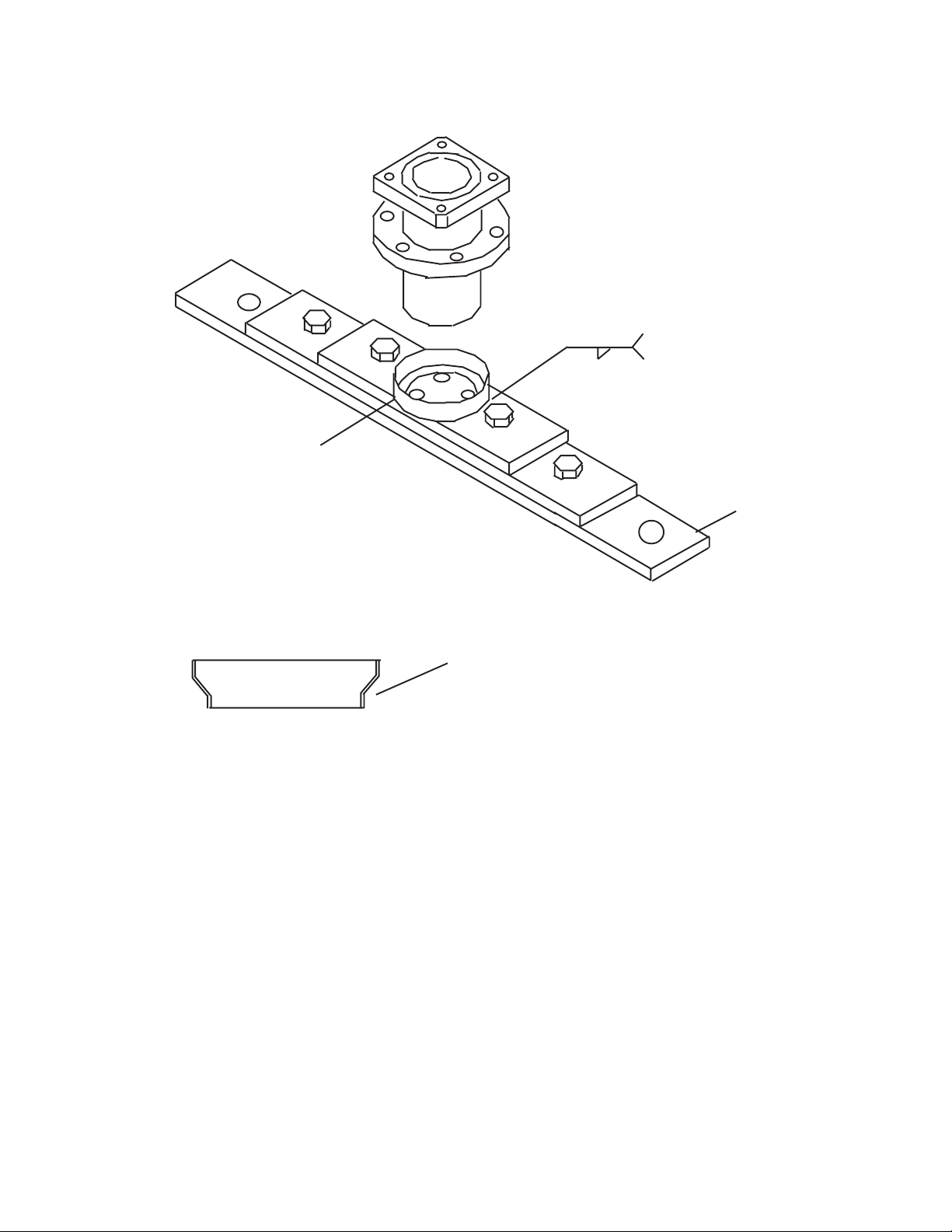
Spindle Oil Filler Kit P/N 02976501:
A Spindle oil filler kit has been developed to provide accurate an easy fill of oil into the spindles
used on all hydraulic powered mowers. The Oil filler Kit P/N 02976501 is available through Alamo
Industrial Parts dept.
Installation requires the replacement of the fill plug with the female quick connect fitting. To
fill the spindle. attach the hose and oil bottle to the spindle by utilizing the quick connect fittings. remove
the vent plug and pump in the oil untill oil is seen at the vent plug opening. reinstall the vent plug and
remove the bottle at the quick connect fitting. The female quick disconnect is designed to be left on
the spindle in place of the fill plug.
Utilization of this spindle fill kit should decrease maintance time and failures by providing
accurate oil fill of the spindle assembly.
Hose (with clamp)
Female Quick Connect
Spindle Assembly
Vent
Fill Plug (Removed)
Oil tank
Figure 1
(with Hand Pump)
This document does not authorize the repair or replacement of parts under warranty
MACHETE
© 2005 Alamo Group Inc.
1-36
Page 43

TECHNICAL INFORMATION BULLETIN No. 080400
Alamo Industrial ™ Technical Services Department
1502 East Walnut
Seguin, Texas 78155
830-372-2708
Models: All Machete, A-boom, Versa Boom, Slopemower.
Boom Mowers which utilize the Joystick operated control valve
with the 02976069 oil Filter Kit installed.
Bulletin No:
080400
Date:
Aug. 4, 2000
Filter Maintenance Procedure:
The following Procedure should be followed to provide the correct maintenance of the
02976066 Filter assembly use as standard on the machete moddel boom and any mower using
Joystick controlled hydraulic system, and filter as optional equipment.
When to Change Filter:
Inspect the visual indicator when the system is operating at normal operating temperature
and under normal flow conditions. When red starts to enter the indicator window, change the element.
This will occur prior to bypass by the filter.
Element Service Procedure:
1. Shut System down a disable tractor so it
cannot be started. Let Oil cool to a safe
temperature.
2. Place a suitable container under the filter to
catch any spillage.
3. Unscrew the filter bowl using the wrench flats
at the bottom of bowl. Remove the bowl and
drain the oil into the container.
4. Pull the element (P/N 02976067) off the adapter
an discard it.
5. Remove the head to bowl seal and discard.
Clean the seal area with a lint free cloth. Install
the new seals as shown taking care not to cut
the new seals.
6. Install the new element onto the element
adapter boss.
7. Thoroughly clean the filter bowl and fill approximately one half full with clean oil.
8. Screw the Bowl onto the head. Torque the
bowl to 30 ft. lbs.
9. Operate the system to expel any trapped air
and check for leaks.
10. Check and fill the tractor oil level as required.
O-Ring
Back Up
Ring
This document does not authorize the repair or replacement of parts under warranty
MACHETE
© 2005 Alamo Group Inc.
1-37
Page 44

TECHNICAL INFORMATION BULLETIN No. 012501
Alamo Industrial ™ Technical Services Department
1502 East Walnut
Seguin, Texas 78155
830-372-2708
Models: Machete Boom Mowers
S/N MB21- 01572 & Up
S/N MB21-01245 & Up
Bulletin No:
012501
Date:
Jan 25, 2001
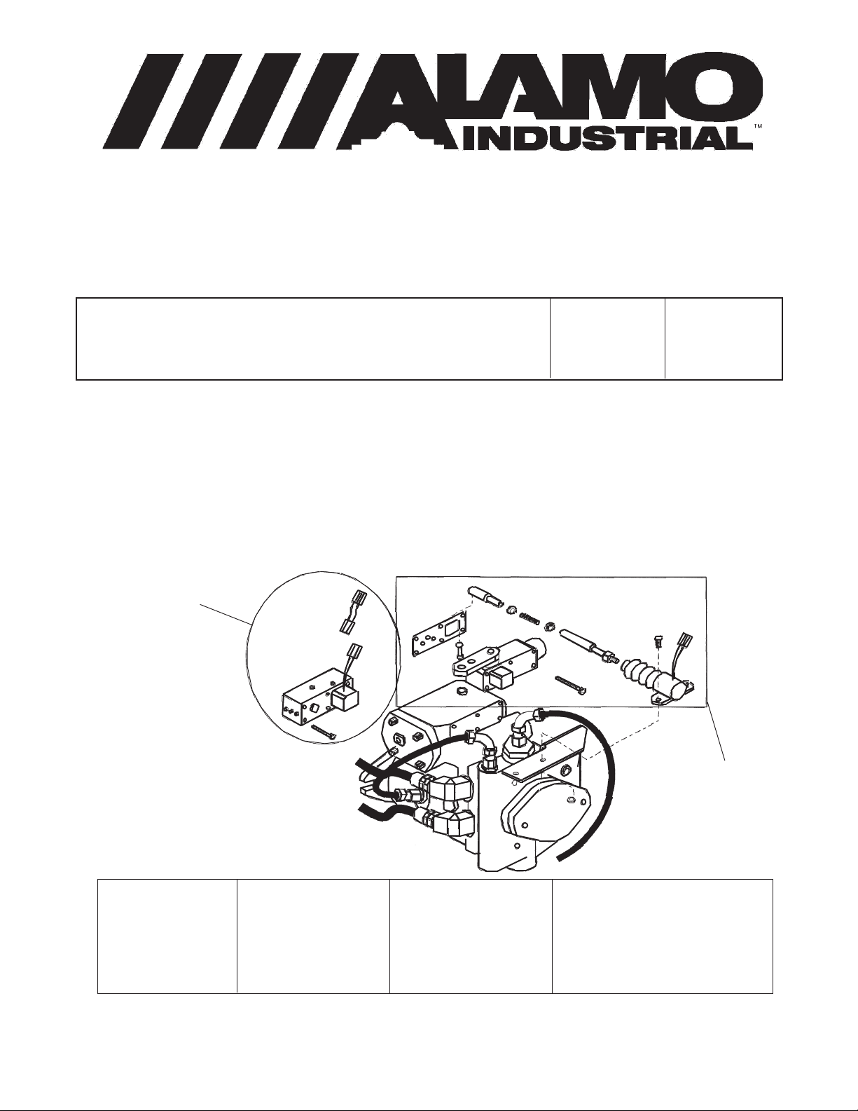
Control Valve Relocation:
The 2001 Machete will reflect a change in the way some of the components are mounted to
the tractor. New Machete units received from the factory, or assembled by dealer after S/N MB2101572 & UP or MB24-01245 & Up will have the control valve in a new location. It will no longer be
mounted on the frame. The Control Valve will be located under the front pump cover in the front of
the tractor. This change was made to better protect the Valve and its components from debris and
other possible damage.
As you can see in figure 1,
the valve is fastened to a plate
that is mounted to the units hydraulic tank. The Pressure Filter
was relocated to a bracket on top
of the tank. Both the Pressure
Filter and the Pump Filter are
accessible and can be changed
with minimal effort. Sepaarate
hose exstension were used to
extend the hose reach to the front
of the tractor. If a hose connection is not easily accessible, then
the valve and mounting plate can
be unfastened an arranged to allow for romm when servicing.
Pump Fiter
Pressure Fiter
Control
Valve
These Changes were
made to better protect the valve
and its components. These
changes will only be seen on the
new units after Jan. 2001 and is
not intended for units already in
use.
Figure 1
This document does not authorize the repair or replacement of parts under warranty
MACHETE
© 2005 Alamo Group Inc.
1-38
Page 45

TECHNICAL INFORMATION BULLETIN No. 040901
Alamo Industrial ™ Technical Services Department
1502 East Walnut
Seguin, Texas 78155
830-372-2708
Models: All Alamo Industrial Products are affected.
Bulletin No:
040901
Date:
Apr. 9, 2001
Change in the availability of rebuilt components:
This bulletin has been published to inform you of a change in the availability of rebuilt parts.
In the past, rebuilt components such as pumps and motors were available for use as spare parts.
That will no longer be the case. The major factor in this decision was the lack of cores that are returned
from the customer.
Since Alamo Industrial will no longer offer rebuilt parts an effort will be made to offer customers
a complete parts listing of all components that are needed as service repairs. The most common
service parts are pumps and motors will now be available for order through Alamo Industrial
Customer Service Department. Likewise, a parts breakdown with Alamo Industrial part numbers will
be provided. The Eaton Pumps and Motors, Danfoss Control Valves will be the first components
available with such a parts breakdown.
It is Our intention to provide a better and more reliable service parts system. This transition
will better suit customer, and provide more timely and efficient parts delivery.
This document does not authorize the repair or replacement of parts under warranty
MACHETE
© 2005 Alamo Group Inc.
1-39
Page 46

TECHNICAL INFORMATION BULLETIN No. 041001-1
Alamo Industrial ™ Technical Services Department
1502 East Walnut
Seguin, Texas 78155
830-372-2708
Models: Machete Boom, MB21-01109 & Down
MB24-01046 & Down
Bulletin No:
041001-2
Date:
Apr. 10, 2001
Filter Kit to Update Control Valve System (Kit P/N 02977366):
There is now available for purchase, a filter kit for Machete units that utilize the Apitech valve.
The Apitech valve was the control valve used before the now current Danfoss valve. You can
differentiate the type valve in two ways. The first is by serial number. The Machete units PRE-Date
the following serial numbers, utilize the Apitech Valve: MB21-01109 & Down, MB24-01046 & Down.
The second way is by visually inspecting the unit. The Apitech valve will have electronic Solenoids
on both the pressure and return sides of the valve, as well as electronic connections on each
solenoid. The Danfoss Control Valve only has electronic connectors on one side. Install the Filter as
described by the Assembly Drawing ( Drawing P/N 02977367) that you will receive when you order
the Filter Kit (Kit P/N 02977366) for the Machete Unit
When to Change Filter:
Inspect the visual indicator when the system is operating at normal operating temperature
and under normal flow conditions. When red starts to enter the indicator window, change the element.
This will occur prior to bypass by the filter.
Element Service Procedure:
1. Shut System down a disable tractor so it cannot be started. Let Oil cool to a safe temperature.
2. Place a suitable container under the filter to catch any spillage.
3. Unscrew the filter bowl using the wrench flats at the bottom of bowl. Remove the bowl and
drain the oil into the container.
4. Pull the element (P/N 02976067) off the adapter an discard it.
5. Remove the head to bowl seal and discard. Clean the seal area with a lint free cloth. Install
the new seals as shown taking care not to cut the new seals.
6. Install the new element onto the element adapter boss.
7. Thoroughly clean the filter bowl and fill approximately one half full with clean oil.
8. Screw the Bowl onto the head. Torque the bowl to 30 ft. lbs.
9. Operate the system to expel any trapped air and check for leaks.
10. Check and fill the tractor oil level as required.
This document does not authorize the repair or replacement of parts under warranty
MACHETE
© 2005 Alamo Group Inc.
1-40
Page 47

TECHNICAL INFORMATION BULLETIN No. 041001-2
Alamo Industrial ™ Technical Services Department
1502 East Walnut
Seguin, Texas 78155
830-372-2708
Models: Machete Boom, MB21-01109 & Down
MB24-01046 & Down
Bulletin No:
041001-1
Date:
Apr. 10, 2001
Filter Maintenance Procedure:
The following Procedure should be followed to provide the correct maintenance of the
02976066 Filter assembly use as standard on the machete moddel boom and any mower using
Joystick controlled hydraulic system, and filter as optional equipment.
When to Change Filter:
Inspect the visual indicator when the system is operating at normal operating temperature
and under normal flow conditions. When red starts to enter the indicator window, change the element.
This will occur prior to bypass by the filter.
Element Service Procedure:
1. Shut System down a disable tractor so it
cannot be started. Let Oil cool to a safe
temperature.
2. Place a suitable container under the filter to
catch any spillage.
3. Unscrew the filter bowl using the wrench flats
at the bottom of bowl. Remove the bowl and
drain the oil into the container.
4. Pull the element (P/N 02976067) off the adapter
an discard it.
5. Remove the head to bowl seal and discard.
Clean the seal area with a lint free cloth. Install
the new seals as shown taking care not to cut
the new seals.
6. Install the new element onto the element
adapter boss.
7. Thoroughly clean the filter bowl and fill approximately one half full with clean oil.
8. Screw the Bowl onto the head. Torque the
bowl to 30 ft. lbs.
9. Operate the system to expel any trapped air
and check for leaks.
10. Check and fill the tractor oil level as required.
O-Ring
Back Up
Ring
This document does not authorize the repair or replacement of parts under warranty
MACHETE
© 2005 Alamo Group Inc.
1-41
Page 48

TECHNICAL INFORMATION BULLETIN No. 041101
Alamo Industrial ™ Technical Services Department
1502 East Walnut
Seguin, Texas 78155
830-372-2708
Models: All Alamo Industrial Products using the
Buzz Bar Head are affected.
Buzz Bar Drive Coupling Design change:
There has been a design
change to the drive coupler
assembly for the Buzz bar
Cutting Head. If a flexible coupler, Alamo Industrial P/N
02974245 (for Machete) or P/
N 02974246 (for A-Boom &
Slopemower), are ordered they
will be a different design. The
new flexible coupler design will
be molded rubber with metal
inserts. The new molded rubber version will directly replace
the machined design using the
same part number. An installation drawing, that describes
the assembly in detail, will be
shipped if a new coupler is
ordered. this bulletin is to inform you of the design change
(see Figure 1) If there are
further questions please contact Alamo Industrial's Technical Service Department. Also
See Manual Insert Sheet P/N
02978337.
Flexible Coupler
Hub
Pulley Sheave
Motor
Bulletin No:
041101
Date:
Apr. 11, 2001
Figure 1
This document does not authorize the repair or replacement of parts under warranty
MACHETE
© 2005 Alamo Group Inc.
1-42
Page 49

TECHNICAL INFORMATION BULLETIN No. 101802
Alamo Industrial ™ Technical Services Department
1502 East Walnut
Seguin, Texas 78155
830-372-2708
Models: All Machete, A-Boom, Versa, Rear Mount, Slopemower,
Brahma, EKII, Hydro 60, Hydro 72 & Hydro 15
All Hydraulic powered Rotary Mower heads that utilize the
# 02960553B, 02960553C and 02968859A Spindle Assemblies.
Bulletin No:
101802
Date:
Oct. 18, 2002
Spindle Bearing Lubrication Update:
Normal maintenance of the # 02960553B, 02960553C and 02968859A Spindle assemblies
has included the addition of NLGI 000 grease to provide proper lubrication of the bearing assemblies.
Due to repeated customer requests, this lubrication requirement has been changed to NLGI EP, #
2 Lithium Wheel Bearing Grease.
Implementation of this grease will allow
improved lubrication especially to the top bearing
as well as substantial improvement of the daily
maintenance requirements.
Spindle Assembly
Conversion:
1. Remove the existing fill plug from the
spindle housing and discard it. (this is the
lower plug in figure 1)
2. Install a standard 1/4" fine thread grease
zert into the fill plug port as shown in figure 1.
3. Remove the Vent plug (Top plug in figure 1)
4. Fill the housing with NLGI EP, # 2 Lithium Grease or equivalent from a standard grease gun
until the new grease is seen in the vent plug hole. (Approximately 2 standard grease tubes
will be required when Spindle Assembly is empty).
5. Clean off any excess or over flow grease and reinstall vent plug.
6. Maintain proper lubrication with 5 pumps of grease into the spindle every 8 hours of use. This
will keep the Spindle bearings lubricated.
7. Always clean excess Grease away from Spindle after greasing Spindle.
Figure 1
Vent
Plug
Grease
Zert
(added)
This document does not authorize the repair or replacement of parts under warranty
MACHETE
© 2005 Alamo Group Inc.
1-43
Page 50

TECHNICAL INFORMATION BULLETIN No. 121802
Alamo Industrial ™ Technical Services Department
1502 East Walnut
Seguin, Texas 78155
830-372-2708
Models: Machete Boom Mowers - All
Brahma Side Mnt Mowers - All
Bulletin No:
121802
Date:
Dec. 18, 2002
Recommended Brands of Hydraulic Oil:
As of November 10 of 2002, Alamo Industrial ™ changed the specification in regard to the
recommended hydraulic oil for use in the current Machete Boom and Brahma mounted mowing
system. This Oil change effects the front mounted 18-gallon oil tank, front mounted pump and motor
circuit of the Machete Boom.
This update to the specifications will better protect against the possibility of internal motor wear
and loss of power.
To comply with the new specifications, the front tank hydraulic oil should be changed to the
recommended ISO rated AW 100 hydraulic Oil (Alamo Industrial Part No. 00751758)
One of the following equivalents can be used as they are equal to the Alamo Industrial ™
recommended hydraulic Oil.
TEXACO: Texaco Rando ® HDZ ISO 100
CHEVRON: Chevron Machine Oil AW ISO 100
SHELL: Shell TELLUS ® Plus Oil ISO 100
PENNZ: PENNZBELL ® AW Hydraulic Oil ISO 100
MOBIL: Mobil Hydraulic Oil AW 100 Code 58304-7
EXXON: Exxon NUTO® H ISO 100
CASTROL: HD PARADENE 100 AW
This document does not authorize the repair or replacement of parts under warranty
MACHETE
© 2005 Alamo Group Inc.
1-44
Page 51

TECHNICAL INFORMATION BULLETIN No. 021802
Alamo Industrial ™ Technical Services Department
1502 East Walnut
Seguin, Texas 78155
830-372-2708
Models:
All Machete™ Boom Mower and
All Brahma™ Side Mnt Mowers
Bulletin No:
021803
WARRANTY REPAIRS:
Effective February 18, 2003:
Warranty repairs to the Machete electric over Hydraulic valves which require
the complete replacement of the valve, will be considered only with utilization of Rebuilt Valves.
To facilitate the Warranty replacement of these valves, the following part numbers
should be used.
Part No. 02971378RB .........Closed Center Load Sense 5 Spool Valve
Part No. 02971379 RB........... Open Center Fixed Displacement 5 Spool Valve
Warranty repairs to the
replacement of the Motor or Pump, will be considered only with utilization of Rebuilt Parts.
Machete or Brahma Mowers which require the complete
Date:
Feb. 18, 2003
To facilitate the Warranty replacement of these parts, the following part numbers
should be used.
Part No. 02967193RB .........Motor, Piston Type (Rebuilt)
Part No. 02969527RB........... Pump, Piston Type (Rebuilt)
Warranty Claims submitted for replacement of these parts using
numbers other than those listed above are subject to denial
This document does not authorize the repair or replacement of parts under warranty
MACHETE
© 2005 Alamo Group Inc.
1-45
Page 52

TECHNICAL INFORMATION BULLETIN No. 041503
Alamo Industrial Technical Services Department
1502 East Walnut
Seguin, Texas 78155
830-372-2708
Models:
All Hydraulic Mowers Mounted on John Deere 6215 (s/n All) , 6415
(s/n 6415M355436), 6320 (s/n 6320H361093), 6420(s/n 6420H354700)
and 6615 (s/n All) Tractors with Tier II emission compliance
Bulletin No:
041503
Factory 5
Spoke Cast
Pulley
Factory
Shouldered
Washer
Factory
Pulley
Retaining Bolt
Figure 1
In an effort to comply with certain requirements in regard to Tier II Emission Standards, Deere and
Company initiated a change to the crank shaft pulley on many of the new 6020 series tractors. This was
a random change, which did not affect all tractors. In addition, a specific serial number break does not
exist to identify the affected units.
The Tier II pulley can be identified as a 5 spoke design as indicated in the figure above (See Figure 1).
This pulley must be changed to the tapered lock, solid cast pulley as shown to allow adaptation of the
required front pump drive system used to power the Alamo Industrial products. (See Figure 2)
To change the pulley:
Remove the original pulley retaining bolt, shouldered washer and pulley. (See Figure 1) Clean nose of
Crankshaft using LOCKTITE® number 7649 clean and cure primer. Place a light layer 2 mm to 3 mm
(.079 - .118 in.) of LOCKTITE ® brand adhesive number 680 (TY15969) to the leading edge of the
crankshaft nose.
Install the replacement pulley (P/N 02979857) If any paint inside of pulley it needs to be removed. Make
certain to align the pulley with crankshaft, install pulley. (See Pulley Figure 3). Do not hammer on
Vibration Damper (Pulley) it must be handled in a way that avoids impact damage. Make certain that
you installed the Locktite primer and adhesive as described in previous step before you installed the
pulley, this is very important.
Figure 2
Date:
April 15, 2003
Replacement
Pulley Part
#02979857
Replacement
Washer Part
#02979829
MACHETE
© 2005 Alamo Group Inc.
Continued Next Page
1-46
Page 53

Information Bulletin 041503 Continued from previous Page
Install the new retaining washer (PN 02979829) so that it fits flat against the pulley. The
original factory washer will not be used. (See Figure 4) Use the original Factory Pulley retaining
Bolt (See Figure 1).
Driveshaft
Side of Pulley
Engine Side of
Pulley
Figure 3
Install the original factory retaining bolt and torque to John Deere Specifications 500 N-m (369 ft. lbs).
Check John Deere Service instructions for to asure proper Torque of Crankshaft Pulley Retaining
Bolt has not changed. (See Figure 1 for original Bolt) . Pulley retaing bolt must be dipped in clean
SAE30 oil before installing bolt.
Install Pulley Adapter. The new Pulley adapter Part # 02979790 to be used with Replacement Pulley
Part # 02979857 is a round plate with 4 threaded holes and four non-threaded holes in it. Notice this
pulley adapter will not have a center hole in it. The Pulley retaining bolt must be tightened before this
adapter is installed because you will not be able to get to the Pulley retaining Bolt after it is installed. The
Non-threaded holes are used to mount the Adapter to the Pulley using bolts # 02979791 (10mm 1.5 P
X 35mm Gr.10.9) & Lockwasher # 00755954 (10 mm).
(LOCKTITE is a registered trademark of Locktite Corp.)
Replacement
Pulley Part
#02979857
Figure 4
Replacement
Washer Part
#02979829
TECHNICAL INFORMATION BULLETIN
No. 041503
Contact:
Alamo Industrial
Technical Services Department
1502 East Walnut
Seguin, Texas 78155
Ph; 830-372-2708 Fax; 830-372-9603
This document does not authorize the repair or replacement of parts under warranty
MACHETE
© 2005 Alamo Group Inc.
1-47
Page 54

TECHNICAL INFORMATION BULLETIN No. 102103
Alamo Industrial ™ Technical Services Department
1502 East Walnut
Seguin, Texas 78155
830-372-2708
Models: All Non-Cab Models with Expanded Metal Side Screens
Retro Fit Kit P/N 02980005
Bulletin No:
102103
Date:
Oct. 21, 2003
Lexan® (Polycarbonate) Shield Upgrade Kit P/N 02980005: (field Install)
Alamo Industrial has designed a Lexan® ( Polycarbonate) Shield that will install on the expanded
metal screen currently used on the Non-Cab models. This is a retro fit kit that is designed to be customer
installed over the expanded metal screen. The Lexan® Sheets will require trimming and the Holes will
have to be drilled in the Lexan
Recommended Tools:
1. Jig Saw or Circular Saw (hand held or table) equipped with plastic cutting blade.
2. Electric Hand Drill, preferably a variable Speed Drill.
3. 3/8" and 1/4" High Speed Steel Drill Bit. (Drill bit should be sharp and in good condition).
4. Measuring Tape or other measuring device.
5. Hand Wrenches for tightening Bolts, do not use air tools to tighten bolts.
6. Straight edge and marker that will write on Lexan.
Lexan Shield Kit Components: (Retro-Fit Kit P/N 02980005 includes:
Part No. Qty Description Part No. Qty Description
02980003 1 Lexan Sheet, Upper 02970004 1 Lexan Sheet, Lower
0461600 20 Bolt, Hex Head 1/4"-20 00024100 20 Flatwasher, Std. 1/4"
02980068 20 Fender Washer, 1/4" 32901C 20 Locknut, 1/4"-20
Protection of Lexan Sheets:
1. Do not remove protective sheet (Paper) from the Lexan® Sheet. This will protect it while you are
working with it. You can drill through this protective sheet as well as cut through it.
2. There are two Lexan® Sheets sent, an upper and a lower. Identify these and mark them to
designate front to rear, inside to outside because once you cut to size to match the existing
Expanded Metal Screen, they cannot be turned around. Cutting these is permanent.
Installation Procedure:
3. Use the measuring tape to get the measurements around your existing Expanded Metal Screen
and write them down, Note there is an Upper and Lower section (See Figure 1).
4. Place the Lexan ® Sheets (Upper and Lower Sheets) on a clean work suface and transfer
your measurements from step 1 to the the Lexan ® Sheets using a Pen or other marker. RE-
CHECK your measurement and when certain they are correct. Cut the sheets out to match
your measurements. Lightly sanding the cut edges will smooth them out and round the outer
edge slightly helping to protect it. Sheets should look like sheets in Figure 2, note the holes will
not be drilled in them yet.
® sheets as well as through the existing expanded metal screen frame
MACHETE
© 2005 Alamo Group Inc.
Continued Next Page
1-48
Page 55

Information Bulletin 102103 Continued from previous Page
5. Securely clamp the cut Lexan sheets onto the expanded metal screen aligning the outer
edges, this can be done upper or lower sheet first. Using a 3/8" drill bit drill the mounting
holes through the lexan sheet in a pattern as in Figure 2. When drilling the holes in the Lexan
Sheet use the drill to mark the metal frame of the expanded metal screen on all the holes.
When all the holes are drilled into the lexan sheet and marked into the metal frame, remove
the clamps and the lexan sheet.
6. Using a 1/4" Bit, drill the holes into the frame of the expanded metal screen with the Lexan
removed. Note you drilled 3/8" holes in the Lexan and 1/4" holes in the frame work. This is
so that the Lexan will not have a binding fit.
7. Install the Bolts as shown in Figure 3. 1 st. bolt
through frame, 2 nd. install the fender washer, 3
rd. remove the protective cover sheet from the
inner side and install the Lexan sheet, 4 th.
install the Flatwasher, 5 th start the Locknuts
onto the bolts but do not tighten them.
8. Once all the bolts, washers and nut are installed
begin to tighten them. DO NOT over tighten
these Locknuts and put the Lexan sheet in a
bind which will crack it. Tighten the Nuts evenly
and only snug them so the Lexan sheet will not
move. Do this with the upper and lower Sheet.
Then remove the protective cover from the
outside of the sheet.
B
Figure 1
A
Upper
C
D
E
F
H
I
Expanded
Metal Screen
G
Lower
Fender Washer
Lexan Shield
Flatwasher
Locknut
Bolt Lexan Shield to
Expanded Metal Screen
Figure 2
Upper
Lexan
Sheet
Lower
Lexan
Sheet
Cut Lexan
Shields
Expanded
Metal
Screen
Bolt
Figure 3
TECHNICAL INFORMATION BULLETIN
No. 102103
This document does not authorize the repair or replacement of parts under warranty
MACHETE
© 2005 Alamo Group Inc.
1-49
Page 56

TECHNICAL INFORMATION BULLETIN No. 011304
Alamo Industrial ™ Technical Services Department
1502 East Walnut
Seguin, Texas 78155
830-372-2708
Models: All Machete Boom, Brahma & A-Boom
Mounted on New Holland "TS" Series Tractors
Bulletin No:
011304
Date:
Jan. 13, 2004
Driveline Update Kit:
Alamo Industrial has designed a new Driveline upgrade kit for units mounted on the New Holland
"TS" Series Tractor, This kit will include all component required to install driveline and pump mount
weldment. Some models the Hoses will have to be changed as well as the tank rail weldments and some
will not have these changed. Always check the Insert Sheet that pertains to the model that the kit is
ordered for.
The Machete will need the Cylinder hoses changed, the Brahma will not need any hoses
replaced, the A-Boom needs only the Suction Hose replaced.
The Machete and Brahma needs the tank rail weldments replaced and the A-Boom will not, the
A-Boom will use the same tank rail weldments. Use the existing hardware to install new Tank Rails.
Kits will include Driveline, Pump Mount, Pump Mount Cover, Required Hardware (nuts Bolts,
washers) and Insert Sheet with mounting instructions. Kit may include hoses and tank rail weldments
depending on model. Use only the instruction Insert Sheet that is included with kit as all kits do not have
the same parts.
KIts Available:
Model Kit P/N Insert Sheet
Machete Boom...........02980404................... 02980638
Brahma...................... 02980631................... 02980639
A-Boom......................02980636................... 02980640
LH Tank Rail Weldment Shown
RH Tank Rail Weldment Not Shown
Figure 1
MACHETE
© 2005 Alamo Group Inc.
Tank Rail Weldment
Continued Next Page
1-50
Page 57

Information Bulletin 011304 Continued from previous Page
2
2
1
1
9
9
Figure 2
Pump End
Clamp Yoke
Pump Mount Cover
Pump Mount Weldment
Time Universal Joints
Driveline Asy
Mounting Bolts
Pulley Spacer
Driveline Mounting Bolts
2345678901
2345678901
Engine Pulley
2345678
2345678
Pump Mounting
Bolts, Use Existing
Hardware
Mounting Bolts
Pump Design may vary with Model
this design for Illustration only
234567890
234567890
Bolts To
Tractor Bolster
MACHETE
© 2005 Alamo Group Inc.
TECHNICAL INFORMATION BULLETIN
No. 011304
This document does not authorize the repair or replacement of parts under warranty
1-51
Page 58

NOTES
MACHETE
© 2005 Alamo Group Inc.
1-52
Page 59

SECTION 2
SERVICE
BULLETINS
(This Book is divided into two Sections)
Section Two - Service Bulletins
1. Service Bulletin No: Service Bulletins are listed by Bulletin Number (Date). Example the
oldest Bulletin will be listed first and the most recent bulletin will be listed last. If more than
one bulletin was written on that day the a dash with a number will added, example -1, -2 etc.
2. Repairs: Service Bulletins are intended to authorize only the repairs listed on It to be made
under warranty or any other circumstance unless specifically instructed to do so.
3. Parts: This is the Rate at which compensation will be allowed under warranty for repair parts.
4. Labor: This is the amount of labor (hours) that are allowed to make this repair under warranty.
5. Parts Disposition: Service Bulletins list the disposition of any parts that are removed during the
repair. If listed removed parts must be held awaiting return to factory if instructed to do so.
6. Termination Date: Service bulletins show a termination date, this is the date that the Bulletin
will be discontinued, Any repairs must be made and all warranty applications filed by the listed
date.
7. All Service Bulletins printed in this Manual will void any previously printed Bulletins. Any
changes in these bulletins are the final version as of the date of this manual.
MACHETE
© 2005 Alamo Group Inc.
2-1
Page 60

SERVICE BULLETIN No. 95161 1
Alamo Industrial Technical Services Department
1502 East Walnut
Seguin, Texas 78155
830-372-2708
Models: Machete Boom Mowers
S/N MB21-01002, 01003, 01004, 01006, 01007, 01008
S/N MB24-PT002, 01002, 01003, 01004, 01005, 01006, 01007
Parts:
100 % at Dealer Net
Labor:
0.5 hr. at Dealer registered
Shop Rate
Old Parts Disposition:
Hold all removed parts for
return
Bulletin No:
951611
(Old # 950011)
Termination Date:
Feb. 1, 1996
Joystick Replacement:
Subject:
The electronic console (Joystick Controls) must be replace on the above listed mowers.
Service Required:
1. Disconnect wiring harness from console at connector at the bottom of control box.
2. Remove the bolts attaching console to stand and install new console.
3. Reconnect to wiring harness, test for proper operation
Parts Required:
Date:
Nov. 16, 1995
Part No. Qty Description
02969819 1 Joystick Controller
See Operators manual or Service Manual
for Wire Harness connections.
Figure 1
Warranty Compensation will be provided following proper filing of warranty claim in accordance with
the Alamo Industrial Warranty Policy. Claim allowance may vary in accordance with laws governing a
specific region. Any Warranty associated with this service bulletin must be within authorized dates.
MACHETE
© 2005 Alamo Group Inc.
2-2
Page 61

SERVICE BULLETIN No. 95291 1-1
Alamo Industrial Technical Services Department
1502 East Walnut
Seguin, Texas 78155
830-372-2708
Models: Machete Boom Mowers
S/N MB21-01002, 01003, 01004, 01006, 01007, 01008
S/N MB24-PT002 through 01007
Parts:
100 % at Dealer Net
Labor:
0.7 hr. at Dealer registered
Shop Rate
Old Parts Disposition:
No Returnable Parts
involved
Bulletin No:
952911-1
(Old # 950014)
Date:
Nov. 29, 1995
Termination Date:
May. 1, 1996
Motor to Spindle Bolt Replacement:
Subject:
Replace motor to spindle bolts with longer bolts. Original Bolts may not keep Motor tight to spindle.
Service Required:
1. Clean the head, especially the area around the Motor and Spindle connection. Remove the four
bolts which attach the motor to the spindle. Lift the motor off the spindle and place it to the side.
2. Place a clean lint free rag over the bearings in the spindle to protect them from contamination.
3. Clean the flange surface of both the motor and spindle of any gasket material or oil.
4. Clean and inspect the threads in the holes, use a thread tap to clean them if needed. Check to
be certain the holes are drilled all the way through the housing, this is important as you will be
installing longer bolts.
5. Check the surface on the motor where the
bolt head tightens. It may be rquired to file
a small portion of this surface in order to
allow for a flat surface onto which the bolt
head can tighten.
6. Remove the rag , and check to be sure that
the spindle is properly lubed.
7. Apply a coating of silicone gasket material
to the motor and spindle housing flanges.
8. Apply a small drop of Locktite to each of the
four new bolts.
9. Install the motor and the four new bolts and
tighten them to the proper torque (120 ft. lbs.).
02891800 Bolt
02961038
Gasket
Spindle
Parts Required:
Part No. Qty Description
02891800 4 Bolts
02961038 1 Gasket
Warranty Compensation will be provided following proper filing of warranty claim in accordance with
the Alamo Industrial Warranty Policy. Claim allowance may vary in accordance with laws governing a
specific region. Any Warranty associated with this service bulletin must be within authorized dates.
Figure 1
MACHETE
© 2005 Alamo Group Inc.
2-3
Page 62

SERVICE BULLETIN No. 95291 1-2
Alamo Industrial Technical Services Department
1502 East Walnut
Seguin, Texas 78155
830-372-2708
Models: Machete Boom Mowers
S/N MB21-01002, 01003, 01004, 01006, 01007, 01008
S/N MB24-PT002 through 01007
Parts:
100 % at Dealer Net
Labor:
0.7 hr. at Dealer registered
Shop Rate
Old Parts Disposition:
Scrap old Parts
Bulletin No:
952911-2
(Old # 950013)
Date:
Nov. 29, 1995
Termination Date:
May. 1, 1996
King Post Pin Replacement: (Longer Pins)
Subject:
Replace King Post Pins with new longer pins
Service Required:
1. Measure the length of the bottom king post pin, this can be done without any disassembly.
2. If Pin measurement is 5-1/4" to 5-3/8", this procedure will not be required.
3. If measurement is 5" or less, replace the pins according to the correct replacement procedure as
outlined in the operators manual and / or Service Manual.
4. Boom must be flat on the floor and boom must be supported with a Hoist. All Hydraulic pressure
must be released for all cylinder. See Machete service manual for this procedure.
5. Remove the pis one at a time, do not remove both pins at the same time and do not operate boom
or tractor until these jobs are finished.
Install the new pin. It may be required
to move boom to align pins. Moving
boom can usually be done by using the
hoist supporting the Boom
7. Do Not drive pins in with a Hammer to
align pins, This will damage the com.ponent
King Post Pins
Parts Required:
Part No. Qty Description
02966797 2 King Post Pin
Figure 1
Warranty Compensation will be provided following proper filing of warranty claim in accordance with
the Alamo Industrial Warranty Policy. Claim allowance may vary in accordance with laws governing a
specific region. Any Warranty associated with this service bulletin must be within authorized dates.
MACHETE
© 2005 Alamo Group Inc.
2-4
Page 63

NOTES
MACHETE
© 2005 Alamo Group Inc.
2-5
Page 64

SERVICE BULLETIN No. 962503-1
Alamo Industrial Technical Services Department
1502 East Walnut
Seguin, Texas 78155
830-372-2708
Models: Machete Boom
Parts:
100 % at Dealer Net
Labor:
1.0 hrs. at Dealer registered
Shop Rate
S/N MB21-01001 to 01020 (& PT002)
S/N MB24-01001 to 01017 (& PT002)
Old Parts Disposition:
No Returnable Parts
involved
Bulletin No:
962503-1
(Old # 960001)
Termination Date:
Sep. 30, 1996
Date:
Mar. 25, 1996
Rear Flap Bracket, Machete Rotary Head:
Subject:
Install rear flap bracket on Machete Rotary Heads. Brackets will aid in deflecting material away
from the tractor.
Service Required:
1. All units with Rotary Heads will be affected in the modification.
2. Secure tractor so it can not be started until you are ready to start it, this will prevent some one
from starting tractor while you are working on it.
2. Clean area to be welded of paint and
debris. Align and Weld bracket to
head as described in Figure 2.
Clean weld and repaint area as
needed.
3. Bolt Flap to new bracket using
hardware provided.
Parts Required:
Part No. Qty Description
02970461 1 Bracket
00007000 1 Bolt
00011100 2 Flatwasher
00015800 1 Locknut
63096300 1 Paint, Spray Can,
Industrial Yellow
The above parts will have to be ordered
separately, they do not come in a kit.
MACHETE
© 2005 Alamo Group Inc.
Figure 1
Continued Next Page
2-6
Page 65

Service Bulletin 962503-1 Continued from previous Page
1/4"
Weld on inside only
Be carefull not to weld to skid shoe
Figure 2
SERVICE BULLETIN
No. 962503-1
Warranty Compensation will be provided following proper filing of warranty claim in accordance with
the Alamo Industrial Warranty Policy. Claim allowance may vary in accordance with laws governing a
specific region. Any Warranty associated with this service bulletin must be within authorized dates.
MACHETE
© 2005 Alamo Group Inc.
2-7
Page 66

SERVICE BULLETIN No. 962503-2
Alamo Industrial Technical Services Department
1502 East Walnut
Seguin, Texas 78155
830-372-2708
Models: Machete Boom Mowers
S/N MB21-01001 to 01015 (& PT002)
S/N MB24-01001 to 01012 (& PT002)
Parts:
100 % at Dealer Net
Labor:
2.0 hr. at Dealer registered
Shop Rate
Bulletin No:
962503-2
(Old # 960002)
Old Parts Disposition:
No Returnable Parts
involved
Termination Date:
Oct. 1, 1996
Date:
Mar. 25, 1996
Lower Crossmember Kit Installation:
Subject:
Install lower frame rail crossmember kit to reduce frame rail deflection and movement.
Service Required:
1. Install Crossmember between frame rails under tractor and aligned with the upright section of
frame rails as shown in figure 1.
2. Using large C-Clamps clamp the crossmember uprigts to the frame rails. The bolts in the
crossmember will need to be loose when you do this, the holes for these bolts are slotted.
3. Weld the uprights of the cross member to the upright of the frame rail on both sides. retighten the
bolts in cross member. Cleand welded are and repaint welded are and crossmember. 2 Cans
Spay Paint, High Gloss Black (Obtain Locally)
Parts Required: Part No. Qty Description
02970118 1 Frame Rail Support Kit
Frame Rail, RH Shown
Frame Rail Support Kit
P/N 02970118
Weld Here both side and
both frame rails
Figure 1
Warranty Compensation will be provided following proper filing of warranty claim in accordance with
the Alamo Industrial Warranty Policy. Claim allowance may vary in accordance with laws governing a
specific region. Any Warranty associated with this service bulletin must be within authorized dates.
MACHETE
© 2005 Alamo Group Inc.
2-8
Page 67

SERVICE BULLETIN No. 962703
Alamo Industrial Technical Services Department
1502 East Walnut
Seguin, Texas 78155
830-372-2708
Models: Machete Boom Mowers & A-Boom Mowers
Parts:
100 % at Dealer Net
Labor:
1.0 hr. at Dealer registered
Shop Rate
Old Parts Disposition:
No Returnable Parts
involved
Bulletin No:
962703
(Old # 960003)
Termination Date:
Oct. 1, 1996
Date:
Mar. 27, 1996
Frame Rail Reinforcement, LH Frame Rail:
Subject:
Add Gusset to Left Frame rail of certain A-Booms and Machetes
Service Required:
1. Weld Gusset, P/N 02970138 to left frame rail as instructed on installation drawing which will be
sent with Gusset when ordered.
2. When welding some thing on a square tube do not weld across the square tube, that will weaken
the square tube. Always try to weld the length of the tube on the corners.
3. Paint Gusset and welded area.
Parts Required:
Part No. Qty Description
02970138 1 Gusset
------------- 1 Can Spay Paint, High Gloss Black (Obtain Locally)
Gusset 02970138
Front
Rear
Left Frame Rail
Weld to outside
of Frame Rail
DO NOT Weld across square tubing when welding
Figure 1
Warranty Compensation will be provided following proper filing of warranty claim in accordance with
the Alamo Industrial Warranty Policy. Claim allowance may vary in accordance with laws governing a
specific region. Any Warranty associated with this service bulletin must be within authorized dates.
MACHETE
© 2005 Alamo Group Inc.
2-9
Page 68

SERVICE BULLETIN No. 962310
Alamo Industrial Technical Services Department
1502 East Walnut
Seguin, Texas 78155
830-372-2708
Models: Machete Boom Mowers
S/N MB21-01001 & Up (except 01044)
S/N MB24-01001 & Up
Parts:
100 % at Dealer Net
Labor:
0.7 hr. at Dealer registered
Shop Rate
Bulletin No:
962310
(Old # 960008)
Old Parts Disposition:
Hold all removed parts for
return
Termination Date:
Feb. 1, 1997
Date:
Oct. 23, 1996
Joystick Control of Boom Movement:
Subject:
Lack of proportional control of the Boom Movement may develope due to the joy stick controls.
Service Required:
1. Operated Boom controls for the lift, dipper and swing function. The Cylinder speeds should be
able to be controlled from very slow to fast without jerking or sudden stop.
2. If lift, dipper and swing function operates smoothly and speeds can be controlled, No service
will be required joystick is working correctly.
3. If lift, dipper or swing function do not operate smoothly, it will be necessary to replace the joystick
control box. Alamo Industrial through testing has found some joysticks were not properly
adjusted from the factory. The returned joysticks have been readjusted, rebuilt and tested. The
rebuilt joystick will be used in this repair.
4. Make certain the ignition switch is in the "OFF" position. Remove the wiring harness from the
bottom of the control box by unscrewing the connector. Remove the mounting bolts from the
bottom of the control box and remove the box.
5. Install the replacement control box (Joystick) in the reverse order and test operate unit.
Parts Required:
Part No. Qty Description
02969819RB 1 Joystick Controller
See Operators manual or Service Manual
for Wire Harness connections.
Figure 1
Warranty Compensation will be provided following proper filing of warranty claim in accordance with
the Alamo Industrial Warranty Policy. Claim allowance may vary in accordance with laws governing a
specific region. Any Warranty associated with this service bulletin must be within authorized dates.
MACHETE
© 2005 Alamo Group Inc.
2-10
Page 69

SERVICE BULLETIN No. 96051 1
Alamo Industrial Technical Services Department
1502 East Walnut
Seguin, Texas 78155
830-372-2708
Models: Machete Boom Mowers
Parts:
100 % at Dealer Net
Labor:
1.0 hrs. at Dealer registered
Shop Rate
Bulletin No:
960511
(Old # 960009)
Old Parts Disposition:
No Returnable Parts
involved
Termination Date:
Feb. 1, 1997
Date:
Nov. 5, 1996
Restrictor Installation Tilt Cylinder Function:
Subject:
Cutting Head Tilt function drops too fast. Install one-way restrictor in tilt circuit to reduce the
lowering speed of the tilt function.
Service Required:
1. Remove the cover from the control valve, clean the control valve of all debris to prevent
contamination from entering system. Make certain that Boom is lower with head resting on the
floor. Make certain that all pressure is relieved from the system and all hoses.
2. Remove and plug the hose from the rod end of the tilt cylinder (Red Tag) at the valve. Remove
the adapter from the valve.
3. Install the new adapter (# 02969400), orifice plate and old adapter as shown in figure 1. Be
certain that the groove in the orifice plate is installed as shown. The Groove should be away from
valve.
4. Reassemble the machine and clean any spilled oil. Test for operation by running through its
cycle to remove any trapped air in system and inspect for leaks.
To Hose
Parts Required:
Part No. Qty Description
02969400 1 Straight Adapter
02969398 1 Orifice Plate .055"
See Operators manual or Service Manual
for Port locations on valve if needed.
Orifie Plate
P/N 02969398
Note orientation
of notch in plate
Notch away from
valve
Figure 1
To Valve
Existing
Adapter
New Adapter
P/N 02969400
Warranty Compensation will be provided following proper filing of warranty claim in accordance with
the Alamo Industrial Warranty Policy. Claim allowance may vary in accordance with laws governing a
specific region. Any Warranty associated with this service bulletin must be within authorized dates.
MACHETE
© 2005 Alamo Group Inc.
2-11
Page 70

SERVICE BULLETIN No. 971903
Alamo Industrial Technical Services Department
1502 East Walnut
Seguin, Texas 78155
830-372-2708
Models: Machete Boom Mowers
Manufactured prior to Mar. 1997
Parts:
100 % at Dealer Net
Labor:
2.5 hrs. at Dealer registered
Shop Rate
Bulletin No:
971903
(Old # 970001A)
Old Parts Disposition:
Hold any removed parts
for warranty decision
Termination Date:
Sep. 1, 1997
Date:
Mar. 19, 1997
Turning Arm - King Pin Upgrades:
Subject:
Boom Hinge Point Pin Upgrades. These repairs are covered in detail on Technical Information
Bulletins # 041797-1 and # 041797-2. These Technical Information Bulletins must be consulted
for detailed instructions for performing the following repairs. Also use Instruction Sheet that will
be included with the Pin Kits
Service Required:
1. See Technical Information Bulletins # 041797-1 and # 041797-2 for detailed instructions on how
to perform these modifications.
2. Caution must always be used when installing new bushing and when aligning the pins. Do Not
try to align the pins by hitting it with a hammer, See operators manual for correct way to align
pins and install bushings. It is recommended that bushings be installed with a bushing driver,
these Bushing drivers are available from Alamo Industrial (See Technical Information Bulletin
# 032697).
Parts Required:
Turning Arm - King Pin Replacement Kits:
(Qty use 1 each)
Part No. Description
02972211 1 Turning Arm Kit
02967679 1 Lift Cyl. Pin Kit, Barrel End
02967675 1 Swing Cyl. Pin Kit, Rod End
02967689 1 Main Pin Replacement
Note: Instruction Sheet is included in Kit. Check with Service Bulletin 972103 (970002A) and
971903 (970001A) as these service bulletins use some of the same parts and cover some of the same
upgrades, so when ordering parts for this service bulletin check so duplicate parts (kits) are not ordered.
MACHETE
© 2005 Alamo Group Inc.
2-12
Continued Next Page
Page 71

Service Bulletin 971903 Continued from previous Page
Weld
Weld
Weld
Weld
Weld
Weld
Weld
Figure 1
SERVICE BULLETIN
No. 971903
Warranty Compensation will be provided following proper filing of warranty claim in accordance with
the Alamo Industrial Warranty Policy. Claim allowance may vary in accordance with laws governing a
specific region. Any Warranty associated with this service bulletin must be within authorized dates.
NOTE: The printing of this Service Bulletin on Oct. 22, 2003 will void any previous versions of this
bulletin number.
MACHETE
© 2005 Alamo Group Inc.
2-13
Page 72

SERVICE BULLETIN No. 972103
Alamo Industrial Technical Services Department
1502 East Walnut
Seguin, Texas 78155
830-372-2708
Models: Machete Boom Mowers
Manufactured prior to Mar. 1997
Parts:
100 % at Dealer Net
Labor:
2.5 hrs. at Dealer registered
Shop Rate
Bulletin No:
972103
(Old # 970002A)
Old Parts Disposition:
Hold any removed parts
for warranty decision
Termination Date:
Sep. 1, 1997
Date:
Mar. 21, 1997
Boom Hinge Point Pin Upgrades:
Subject:
Boom Hinge Point Pin Upgrades. These repairs are covered in detail on Technical Information
Bulletins # 041797-1 and # 041797-2. These Technical Information Bulletins must be consulted
for detailed instructions for performing the following repairs. Also use Instruction Sheet that will
be included with the Pin Kits
Service Required:
1. See Technical Information Bulletins # 041797-1 and # 041797-2 for detailed instructions on how
to perform these modifications.
2. Caution must always be used when installing new bushing and when aligning the pins. Do Not
try to align the pins by hitting it with a hammer, See operators manual for correct way to align
pins and install bushings. It is recommended that bushings be installed with a bushing driver,
these Bushing drivers are available from Alamo Industrial (See Technical Information Bulletin
# 032697).
3. Install the top bushing flush with the bottom side and the bottom bushing flush
with the top side, this is because turning will have to go between lugs of frame.
Parts Required:
Hitch Post Replacement Kits:
(Qty use 1 each)
Use Locktite 271 brand adhesive when installing new bushings
Part No. Description
02967689 1 Main Pin
02967693 1 Dipper to Lift Pin
02967687 1 Dipper to Hitch Post Pin
02968803 8 Bushings
Note: Instruction Sheet is included in Kit. Check with Service Bulletin 972103 (970002A) and
971903 (970001A) as these service bulletins use some of the same parts and cover some of the same
upgrades, so when ordering parts for this service bulletin check so duplicate parts (kits) are not ordered.
MACHETE
© 2005 Alamo Group Inc.
2-14
Continued Next Page
Page 73

Service Bulletin 972103 Continued from previous Page
Weld
Weld
Weld
Weld
Weld
Weld
Weld
Figure 1
SERVICE BULLETIN
No. 972103
Warranty Compensation will be provided following proper filing of warranty claim in accordance with
the Alamo Industrial Warranty Policy. Claim allowance may vary in accordance with laws governing a
specific region. Any Warranty associated with this service bulletin must be within authorized dates.
NOTE: The printing of this Service Bulletin on Oct. 22, 2003 will void any previous versions of this
bulletin number.
MACHETE
© 2005 Alamo Group Inc.
2-15
Page 74

SERVICE BULLETIN No. 971404
Alamo Industrial Technical Services Department
1502 East Walnut
Seguin, Texas 78155
830-372-2708
Models: Machete Boom Mowers
Parts:
100 % at Dealer Net
Labor:
1.5 hrs. at Dealer registered
Shop Rate
Bulletin No:
971404
(Old # 970004A)
Old Parts Disposition:
No Returnable Parts
involved
Termination Date:
Oct. 1, 1997
Date:
Apr. 14, 1997
Restrictor Installation Lift & Dipper Cylinder Function:
Subject:
Lift and/or dipper functions drop to fast. When both functions are combined, sudden drop may
occur. Install one way restrictors in the dipper cylinder rod end port and the tilt cylinder barrel end port
of the control valve to prevent the sudden drop of the boom and damage to the boom and frame.
Service Required:
1. Remove the cover from the control valve, clean the control valve of all debris to prevent
contamination from entering system. Make certain that Boom is lower with head resting on the
floor. Make certain that all pressure is relieved from the system and all hoses.
2. Remove and plug the hose from the rod end of the dipper cylinder (Blue Tag) at the valve.
Remove the adapter from the valve.
3. Install the new adapter (# 02972159), orifice plate and old adapter as shown in figure 1. Be
certain that the groove in the orifice plate is installed as shown. Perform the same procedure
to the barrel end of the lift cylinder valve port (Orange and White Tag)
4. Reassemble the machine and clean any spilled oil. Test for operation by running through its
cycle to remove any trapped air in system and inspect for leaks.
To Hose
Parts Required:
Existing
Part No. Qty Description
02972159 2 Straight Adapter
02969398 2 Orifice Plate .055"
Orifie Plate
P/N 02969398
Note orientation
of notch in plate
Adapter
New Adapter
P/N 02972159
Notch away from
See Operators manual or Service Manual
for Port locations on valve if needed.
Warranty Compensation will be provided following proper filing of warranty claim in accordance with
the Alamo Industrial Warranty Policy. Claim allowance may vary in accordance with laws governing a
specific region. Any Warranty associated with this service bulletin must be within authorized dates.
valve
Figure 1
To Valve
MACHETE
© 2005 Alamo Group Inc.
2-16
Page 75

SERVICE BULLETIN No. 973107
Alamo Industrial Technical Services Department
1502 East Walnut
Seguin, Texas 78155
830-372-2708
Models: Machete Boom
S/N MB21-01109 & Up +
S/N MB24-01046 & Up + MB24-01001 to 01045 that have been updated
Parts:
100 % at Dealer Net
MB21-01001 to 01108 that have been updated
Labor:
3.5 hrs. at Dealer registered
Shop Rate
Old Parts Disposition:
Retain All parts for
Warranty Return
Bulletin No:
973107
(Old # 970008A)
Termination Date:
Nov. 15, 1997
Date:
Jul. 31, 1997
Upper King Pin Bushing Slipping:
Subject:
It is possible that the upper King Pin Bushing may loose retention and work down from the bore.
This could result in damage to the frame, Pin and Arm.
Service Required:
1. Visually inspect the bushing location in the top king pin bore. The bushing should be flush with
the bottom of the bore.
2. If the Bushing is in the proper place there will be no need to make this repair.
3. If the busing appears to have moved downward in the bore, refer to the King Pin bushing
replacement section in the operators manual / Service Manual for the proper procedure to
support the boom while removing it. The turning arm and boom will need to be removed.
Using Locktite Brand 271 adhesive
(Purchased Locally) Install new
bushings in the upper and lower
Pin holes. Use proper Drivers
when installing busings.
Parts Required:
Part No. Qty Description
02968804 2 King Pin Bushing
------------ 1 Locktite Brand 271
Figure 1
Warranty Compensation will be provided following proper filing of warranty claim in accordance with
the Alamo Industrial Warranty Policy. Claim allowance may vary in accordance with laws governing a
specific region. Any Warranty associated with this service bulletin must be within authorized dates.
MACHETE
© 2005 Alamo Group Inc.
2-17
Page 76

SERVICE BULLETIN No. 970108
Alamo Industrial Technical Services Department
1502 East Walnut
Seguin, Texas 78155
830-372-2708
Models: Machete Boom
MR 60" Rotary Heads S/N 01039 & Up
Parts:
100 % at Dealer Net
Labor:
1.0 hrs. at Dealer registered
Shop Rate
Bulletin No:
970108
(Old # 970009A)
Old Parts Disposition:
Scrap Old Parts
Termination Date:
Aug. 31, 1997
Date:
Aug. 1, 1997
Blade Bolt Inspection / Recall:
Subject:
The Blade Bolt Nut Retaining Roll Pin Bore may be oversized and could allow the roll pin to
become loose in the bore. The loose roll pin could therfore allow the blade bolt Nut to loose
torque.
Service Required:
1. Visually inspect and check the fit of the roll pin. If it is loose or has come loose replace the Blade
Bolt, Blade Bolt Nut and Roll Pin on the above listed serial numbered units.
2. Torque the Blade Bolt to 600 ft. lbs. before installing the new Roll Pin.
Parts Required:
Part No. Qty Description
02782900 2 Blade Bolt
00020900 2 Nut
00023200 2 Roll Pin
Figure 1
Warranty Compensation will be provided following proper filing of warranty claim in accordance with
the Alamo Industrial Warranty Policy. Claim allowance may vary in accordance with laws governing a
specific region. Any Warranty associated with this service bulletin must be within authorized dates.
MACHETE
© 2005 Alamo Group Inc.
2-18
Page 77

SERVICE BULLETIN No. 990303
Alamo Industrial Technical Services Department
1502 East Walnut
Seguin, Texas 78155
830-372-2708
Models: Machete Boom mounted on JD 6000 2 & 4 WD
S/N MB21-01001 to 01324
S/N MB24-01001 to 01165
Parts:
100 % at Dealer Net
Labor:
4.8 hrs. at Dealer registered
Shop Rate
Old Parts Disposition:
No Returnable Parts
involved
Bulletin No:
990303
(Old # 990002A)
Termination Date:
Jul. 31, 1999
Date:
Mar. 3, 1999
Lower Cross Member Reinforcement Kit P/N 02974182:
Subject:
Support gussets have been added to the lower crossmember frame support
Service Required:
1. Secure the tractor to facilitate a safe repair, (Engine off, Park brake on, Key Secured & etc..).
2. Using the hardware provided, line up the holes in the plates with the those in the tractor frame
and attach the gusset plates to each side of the tractor over the lower crossmember as shown
in the drawing provided with the kit. NOTE: The gusset is made at an exaggerated length to
accommodate the possibility of varying distances between the crossmember and the tractor
frame. Some trimming of the gusset may be required.
3. Utilize a continuous 1/4" weld to attach the bottom of the gusset to the lower crossmember
between the two crossmember bolts on each side of the tractor as illustrated in figure 1 and in
the assembly drawing provided with the kit. Weld both sides of gusset.
4. Torque the four mounting bolts that attach gussets to tractor frame to 300 ft. lbs. (407 Nm)
5. Clean the welded area and paint with high gloss Black paint.
Parts Required: (order Kit #02974182)
Part No. Qty Description
02974182 1 Support Gusset Kit
P/N 02974182 Kit includes
Part No. Qty Description
02974181 2 Rail Gusset
00000200 4 Nut
00003901 4 Lockwasher
02978600 4 Bolt
02977386 1 Instruction Drawing
Front of Tractor
Gusset
# 02974181
1/4"
1/4"
Gusset
# 02974181
Figure 1
Warranty Compensation will be provided following proper filing of warranty claim in accordance with
the Alamo Industrial Warranty Policy. Claim allowance may vary in accordance with laws governing a
specific region. Any Warranty associated with this service bulletin must be within authorized dates.
MACHETE
© 2005 Alamo Group Inc.
2-19
Page 78

SERVICE BULLETIN No. 992704
Alamo Industrial Technical Services Department
1502 East Walnut
Seguin, Texas 78155
830-372-2708
Models: New Holland tractors T7740 & T6640
(S/N Range listed below)
New Holland Tractors with Alamo Industrial Units mounted on
them (only S/N and model tractors listed below)
Parts:
100 % at Dealer Net
Labor:
0 hr. (See New Holland
Service Bulletin 399)
Old Parts Disposition:
(see New Holland Service
Bulletin 399)
Bulletin No:
992704
(Old # 990003A)
Termination Date:
Sep. 30, 1999
Date:
Apr. 27, 1999
New Holland T7740 & T6640 A/C Drier Campaign:
Subject:
In order to increase customer satisfaction, New Holland is providing a new Air conditioner Receiver
Drier Kit for the S/N units detailed in new Holland Service Campaign 399. The specifics to this bulletin are
provided by the New Holland Bulletin, The purpose of this bulletin is only to inform you of the work that needs
to be done per New Holland Bulletin and not to authorize any work on the behalf of Alamo Industrial or any
of their affiliated companies. If in Question you should consult your New Holland Dealer for details of
repairs.
Units Serial Numbers: (Model T 7740)
084228B 084349B 084350B 084352B 084359B 084476B 084549B 084550B 084570B 084571B
084599B 084627B 084629B 084632B 084633B 084635B 084636B 084647B 084648B 084652B
084661B 084800B 084850B 084964B 084966B 084967B 085607B 086462B 086470B 086471B
086472B 086503B 086504B 086505B 086589B 086648B 086649B
(Model T6640)
084230B 084351B 084411B 084412B 084526B 084529B 084816B 084818B 084832B 084833B
084834B 084847B 084849B 084963B 084965B 086484B 086485B 086486B 086487B 086488B
Service Required:
See New Holland Service Campaign 399 for Service details.
Parts Required:
See New Holland Service Campaign 399 for Parts requirements
Special Note:
This Service Bulletin does not authorize any repairs on behalf of Alamo Industrial, its strictly to
inform you of New Holland Service Campaign 399.
Warranty Compensation will be provided following proper filing of warranty claim in accordance with
the Alamo Industrial Warranty Policy. Claim allowance may vary in accordance with laws governing a
specific region. Any Warranty associated with this service bulletin must be within authorized dates.
MACHETE
© 2005 Alamo Group Inc.
2-20
Page 79

SERVICE BULLETIN No. 99191 1
Alamo Industrial Technical Services Department
1502 East Walnut
Seguin, Texas 78155
830-372-2708
Models: All New Holland TS Tractors w/ Cabs & S/N less than
115012B (date code 8L18) plus All New Holland TS Tractors with
or without Cab & S/N less than 110026B (date code 8j09)
Parts:
100 % at Dealer Net
Labor:
0 hr. (See New Holland
Service Bulletin 409)
Old Parts Disposition:
(see New Holland Service
Bulletin 409)
Bulletin No:
991911
(Old # 990005A)
Termination Date:
Apr. 30, 2000
Date:
Nov. 19, 1999
New Holland TS Tractor Inspection Campaign:
Subject:
In order to increase customer satisfaction, New Holland is requesting inspection of some tractors
(See S/N's listed below) detailed in new Holland Service Campaign 409. The specifics to this bulletin are
provided by the New Holland Bulletin, The purpose of this bulletin is only to inform you of the work that needs
to be done per New Holland Bulletin and not to authorize any work on the behalf of Alamo Industrial or any
of their affiliated companies. If in Question you should consult your New Holland Dealer for details of
repairs.
Units Serial Numbers:
All New Holland TS Tractors w/ Cabs & S/N less than 115012B (date code 8L18) plus All New
Holland TS Tractors with or without Cab & S/N less than 110026B (date code 8j09)
Service Required:
See New Holland Service Campaign 409 for Service details.
Parts Required:
See New Holland Service Campaign 409 for Parts requirements
Special Note:
This Service Bulletin does not authorize any repairs on behalf of Alamo Industrial, its strictly to
inform you of New Holland Service Campaign 409.
Warranty Compensation will be provided following proper filing of warranty claim in accordance with
the Alamo Industrial Warranty Policy. Claim allowance may vary in accordance with laws governing a
specific region. Any Warranty associated with this service bulletin must be within authorized dates.
MACHETE
© 2005 Alamo Group Inc.
2-21
Page 80

SERVICE BULLETIN No. 991012
Alamo Industrial Technical Services Department
1502 East Walnut
Seguin, Texas 78155
830-372-2708
Models: Machete Boom
Parts:
100 % at Dealer Net
Labor:
3.8 hrs. at Dealer registered
Shop Rate
S/N MB21-01001 to 01404
S/N MB24-01001 to 01196
Old Parts Disposition:
Hold all Parts involved fo
Warranty Return
Bulletin No:
991012
(Old # 990005A)
Termination Date:
Jun 1, 2000
Date:
Dec. 10, 1999
Turning Arm Pin Update Kit P/N 02974182:
Subject:
Machete Boom Mower Turning Arm Main Pin Retaining Design Update to increase the durability
of the main Pin retaining device.
Service Required:
1. Secure the tractor to facilitate a safe repair, (Engine off, Park brake on, Key Secured & etc..).
You will need a Machete Operators Manual and a Machete Service Manual, these are available
from Alamo Industrial. It is recommended that these manuals are on hand.
2. This will require drilling to install a larger Retaining Bolt and welding to install the Snap Ring
grooved boss (See Figure 1) on the bottom of the Turning Arm Pin, The Old retaining Bolt at the
bottom of the Pin is a 3/8", this will be removed and the hole will need to be drilled out to a 1/2"
to accept the new larger bolt.
3. Make sure that the Boom is out stretched and the head is setting flat on the Floor (Ground). Make
certain that all hydraulic pressure is relieved from the system, this will need to be done manually
at the valve (See Machete Service Manual for this procedure).
4. Support Boom with a hoist as shown in the operators manual and/or service manual before
beginning work on retaining pin.
5. From the under side use a 1/2" thick steel plate and a hydraulic Jack up under turning arm pin
to prevent the pin from falling out when the retaining bolt is removed. Remove the 3/8" retaining
bolt and drill the hole out to a 1/2" hole so you can install the 1/2" Retaining Bolt (See Figure 3)
6. With the new 1/2" retaining bolt installed (do not remove or lower Jack without retaining Bolt
installed) lower the supporting hydraulic Jack and 1/2" steel plate but do not remove it. (See
Figure 3).
7. Install the new Grooved Snap Ring Boss up under the existing Boss that is welded to the turning
arm. Making certain that the OD of new boss is aligned with the OD of the old one, if it is not
aligned the ID of the boss's will not be aligned and Pin cannot pass through it. Using the 1/2" steel
plate and the hydraulic jack, raise jack till there is enough pressure on new boss to hold it
straight and aligned with the existing one. Do Not apply so much pressure that you distort the
new boss. (See Figure 4)
8. Weld the new Snap Ring Grooved Boss to the existing boss. Lower the Plate and Hydraulic Jack
to remove them. Install the New Snap Ring into the groove of the new boss. The purpose of
this snap ring is to keep the pivot pin from dropping out the bottom if the retaining bolt breaks
or comes out.
MACHETE
Continued Next Page
© 2005 Alamo Group Inc.
2-22
Page 81

Service Bulletin 991012 Continued from previous Page
8
8
8
9
12
12
9. Remove Supporting Hoist and all Jacks. Check to make certain Retaining Bolt Nut is tightened,
Snap ring is installed and seated into groove. Start and Test movement of Boom trough the
Swing functions to make sure it move freely and is not binding.
Parts Required: (order Kit #02975672)
Part No. Qty Description
02975672 1 Turning Arm
Update Kit
63096300 1 Paint, Spray Can,
Industrial Yellow
Nut and Bolt
234567
234567
Snap Ring
Boss w/ Snap
Ring Groove
Figure 1
P/N 02975672 Kit includes these items
Part No. Qty Description
02956765 1 Bolt
00015800 1 Nut
02975430 1 Boss With Groove
02975429 1 Snap Ring Groove
Turning Arm Pin
Main Frame
ccccccccccccccccccc
ccccccccccccccccccccccccc
ccccccccccccccccccccccccccc
cccccccccc
Turning Arm
Retaining Bolt
Figure 2
Turning Arm Pin
Turning Arm Pin
Main Frame
Main Frame
Turning Arm
Retaining Bolt
Existing Boss
Grooved Boss
ccccccccccccccccccc
ccccccccccccccccccccccccc
ccccccccccccccccccccccccccc
234567
Turning Arm
cccccccccc
Retaining Bolt
1/2" Steel Plate
ccccccccccccccccccc
ccccccccccccccccccccccccc
ccccccccccccccccccccccccccc
2345678
cccccccccc
1/2" Steel Plate
Hydraulic Jack
Hydraulic Jack
Figure 3
Figure 4
SERVICE BULLETIN
No. 991012
Warranty Compensation will be provided following proper filing of warranty claim in accordance with
the Alamo Industrial Warranty Policy. Claim allowance may vary in accordance with laws governing a
specific region. Any Warranty associated with this service bulletin must be within authorized dates.
MACHETE
© 2005 Alamo Group Inc.
2-23
Page 82

SERVICE BULLETIN No. 002908
Alamo Industrial Technical Services Department
1502 East Walnut
Seguin, Texas 78155
830-372-2708
Models: Machete Boom
Parts:
100 % at Dealer Net
Labor:
3.5 hrs. at Dealer registered
Shop Rate
S/N MB21-01001 to 01514
S/N MB24-01001 to 01235
Old Parts Disposition:
No Returnable Parts
involved
Bulletin No:
002908
(Old # 200004)
Termination Date:
Dec 1, 2000
Date:
Aug. 29, 2000
Dipper Boom Reinforcement Plates:
Subject:
Loads and the resulting stress incurred during heavy to abusive operation of the Machete Boom
may allow for fracture of the outer (Dipper) Boom at the welds which attach the base end mount
of the Head Tilt Cylinder.
Service Required: All outer (Dipper) Booms should be reinforced with the correct Plates welded to
both sides of the Boom.
1. Follow any and all safety instructions provided, Operators Manual and Instruction Sheets.
2. Position the Boom so Boom arm is fully extended and mower head is resting on the ground.
3. Secure the Tractor, turn off the engine, engage Parking Brake and remove Tractor Key.
4. Use wire brush to remove the paint from the area to be welded under the head tilt cylinder mount.
5. Clamp correct plates to each side of the dipper arm under head tilt cyl. mount (See Figure 1).
6. Weld the plate completely using 7018 rod or equivalent.
7. Let cool, clean and paint. Reinstall the required decals if desired.
Parts Required: (MB21 & MB24 use different Plates & use 2 Plates per repair)
Part No. Qty Description
02976655 2 Repair Plate (MB21 Model)
02976656 2 Repair Plate (MB24 Model)
63096300 1 Paint, Spray Can, Industrial Yellow
02968953 2 Decal, Machete Name
Repair Plates
Figure 1
Warranty Compensation will be provided following proper filing of warranty claim in accordance with
the Alamo Industrial Warranty Policy. Claim allowance may vary in accordance with laws governing a
specific region. Any Warranty associated with this service bulletin must be within authorized dates.
MACHETE
© 2005 Alamo Group Inc.
2-24
Page 83

SERVICE BULLETIN No. 000510
Alamo Industrial Technical Services Department
1502 East Walnut
Seguin, Texas 78155
830-372-2708
Models: Machete Boom
Parts:
100 % at Dealer Net
Labor:
0.5 hrs. at Dealer registered
Shop Rate
S/N MB21-01360 to 01458
S/N MB24-01190 & 01209
Old Parts Disposition:
No Returnable Parts
involved
Bulletin No:
000510
(Old # 200006)
Termination Date:
Dec 15, 2000
Date:
Oct. 5, 2000
Valve Pressure Filter Kit:
Subject:
A new filter kit P/N 02976069 has been developed and must be installed to help prevent some
contamination failures of the control valve system due to normal gear and brake wear within the
tractor hydraulic system. This new filter system has an indicator that will show when the filter
is plugged, see Technical Information Bulletin 032200 for more detail.
Service Required: Use the instructions provided with each kit to install the filter onto the control valve.
Parts Required: Order Pressure Filter Kit P/N 02976069 which includes,
Part No. Qty Description
02975187 1 Elbow
02976066 1 Filter Assembly
02976068 1 Instruction Sheet
02976076 1 Elbow
Above part are include in Kit P/N 02976069
Visual Indicater - Bypass
O-Ring
Filter Head
O-Ring
Note: The new filter will mount on the Inlet
(pressure) side of the control valve which
is mounted on the right hand frame rail. The
hardware (Elbows) and instruction sheet are
included. Read these prior to beginning any
repairs or modifications. Always refer to
operators manual for safe procedures when
working around equipment.
Filter Element
O-Ring
Back Up Ring
Filter Bow
l
Figure 1
Warranty Compensation will be provided following proper filing of warranty claim in accordance with
the Alamo Industrial Warranty Policy. Claim allowance may vary in accordance with laws governing a
specific region. Any Warranty associated with this service bulletin must be within authorized dates.
MACHETE
© 2005 Alamo Group Inc.
2-25
Page 84

SERVICE BULLETIN No. 010607
Alamo Industrial Technical Services Department
1502 East Walnut
Seguin, Texas 78155
830-372-2708
Models: Machete Boom, A-Boom & Slope Mower Models
with Buzz Bar Head Option
Parts:
100 % at Dealer Net
Labor:
2.5 hrs. at Dealer registered
Shop Rate
Old Parts Disposition:
Hold All Parts for Return
under Warranty Policy
Bulletin No:
010607
(Old # 200102)
Termination Date:
Sep 28, 2001
Date:
Jul. 6, 2001
Buzz Bar Head Motor Coupler Re-Design:
Subject:
Failures of the Motor to drive spindle molded coupler require inspection of the drive system and
possible replacement of the coupler parts.
Service Required: The Buzz bar drive system must be updated to the new molded rubber coupling
design prior to the implementation of this Service Bulletin. Refer to Technical Information Bulletin
041101 is related to this Service Bulletin.
The drive system will require inspection and possible replacement to ensure proper alignment
with the drive sheave.
There has been a design change to the drive coupler assembly for the Buzz bar Cutting Head.
If a flexible coupler, Alamo Industrial P/N 02974245 (for Machete) or P/N 02974246 (for A-Boom &
Slopemower), are ordered they will be a different design. The new flexible coupler design will be molded
rubber with metal inserts. The new molded rubber version will directly replace the machined design
using the same part number. An installation drawing, that describes the assembly in detail, will be
shipped if a new coupler is ordered. This bulletin is to inform you of the design change. If there are further
questions please contact Alamo Industrial's Technical Service Department.
Parts Required: Flexible Couple Repair Kits
Part No. Qty Description
02974245 1 Flexible Coupler Repair Kit. (For Machete Models)
02974246 1 Flexible Coupler Repair Kit. (For All Other Models)
Kits above will include the required parts as well as the required Hardware, The Kits will also
include an Instruction Sheet P/N 02977380 which has details on how to perform repairs.
Warranty Compensation will be provided following proper filing of warranty claim in accordance with
the Alamo Industrial Warranty Policy. Claim allowance may vary in accordance with laws governing a
specific region. Any Warranty associated with this service bulletin must be within authorized dates.
MACHETE
© 2005 Alamo Group Inc.
2-26
Page 85

SERVICE BULLETIN No. 021202
Alamo Industrial Technical Services Department
1502 East Walnut
Seguin, Texas 78155
830-372-2708
Models: Machete Boom, A-Boom & Slope Mower Models
with Buzz Bar Head Option
Parts:
100 % at Dealer Net
Labor:
5.0 hrs. at Dealer registered
Shop Rate
Old Parts Disposition:
Hold All Parts for Return
under Warranty Policy
Bulletin No:
021202
Date:
Feb. 12, 2002
Termination Date:
May 20, 2002
Buzz Bar Head Motor Coupler Coupler Update Kit:
Subject:
Buzz Bar Motor to Spindle drive components may fail prematurely due to misalignment of the
Motor and Spindle. Complete instructions for changing Buzz Bar motor to spindle components for
Machete, A-Boom, Versa Boom, Slopemower & Rear Mount Boom units will be provided with each Kit.
Service Required: Use Information that is included with appropriate kit listed below, to change Drive
Spindle, Motor Mount, and Motor Coupler components on all Buzz Bar Head Attachments for the Alamo
Industrial Boom Models manufactured before Feb. 2002
Parts Required: Two Service Kits are available. (These are major Update Kits)
Part No. Qty Description
02978335 1 Coupler Drive Asy Repair Kit. (For Machete Models)
02978336 1 Coupler Drive Asy Repair Kit. (For All Other Models)
Kits above will include the required parts as well as the required Hardware, The Kits will also
include an Instruction Sheet P/N 02978337 which has details on how to perform repairs. Read these
instruction sheets completely before beginning any repairs. If any problems please contact Alamo
Industrial Technical Service Department for further details.
NOTE: This Service Bulletin Printed this date Oct. 22, 2003 will void any other version of this service
bulletin printed prior to this date. Termination date for this service Bulletin was May 20, 2002.
Warranty Compensation will be provided following proper filing of warranty claim in accordance with
the Alamo Industrial Warranty Policy. Claim allowance may vary in accordance with laws governing a
specific region. Any Warranty associated with this service bulletin must be within authorized dates.
MACHETE
© 2005 Alamo Group Inc.
2-27
Page 86

SERVICE BULLETIN No. 030702
1
1
1
1
1
1
1
1
1
1
1
1
1
1
Alamo Industrial Technical Services Department
1502 East Walnut
Seguin, Texas 78155
830-372-2708
Models: Rotary Heads using Blade Bolt No. 02782900
with Date Code on Bolt of 11-02 & 02782900 Blade Bolts in Parts
Stock with the 11-02 date code.
Parts:
100 % at Dealer Net
Labor:
Will be evaluated on a case
by case basis.
Old Parts Disposition:
Hold All Parts for Return
under Warranty Policy
Bulletin No:
030702
(Old #1020703)
Date:
Feb. 7, 2003
Termination Date:
Apr. 15, 2003
Blade Bolt Inspection:
Subject:
Quality inspections revealed the potential for cracking of the Blade Bolt. Cracks are the result
of manufacturing procedures and will be present on the bolts prior to installation on the mower. This
is pertaining to a Date code which is stamped on the threaded end of the bolt, Date Code 11-02.
Service Required:
1. Inspect all Bolts in Parts stock and those on the effected mowers by checking the dated code
on the Blade Bolt.
2. If Blade Bolts do not have the 11-02 date code no service will be required.
3. If the Date code 11-02 is there check the Bolt for any cracks in them, If the bolts are installed
on the mower they will have to be removed to check.
4. If they check OK reinstall them and torque them to 600 ft. lbs. and reinstall roll pins.
5. If they have cracks replace them with new ones, install the new bolts and torque to 600 ft. lbs.
Reinstall roll pin.
Parts Required:
Part No. Qty Description
02782900 a/r Blade Bolt
Note: Always check Date Code and
Part Number of blade bolt before
performing any repairs as described
in this Service Bulletin as not all Blade
will have the same date code. Only
Blade bolts with 11-02 date code will be
considered for warranty consideration.
Alamo Logo &
Part No.
Stamped on
Head End
(P/N 02782900)
234567890
234567890
234567890
234567890
234567890
234567890
234567890
234567890
234567890
234567890
234567890
234567890
234567890
234567890
Date Code
Stamped on this
end (11-02 =
Nov. 2002)
Figure 1
Warranty Compensation will be provided following proper filing of warranty claim in accordance with
the Alamo Industrial Warranty Policy. Claim allowance may vary in accordance with laws governing a
specific region. Any Warranty associated with this service bulletin must be within authorized dates.
MACHETE
© 2005 Alamo Group Inc.
2-28
Page 87

SERVICE BULLETIN No. 050504
12
12
12
12
12
3
3
3
3
3
3
3
3
3
3
3
3
3
4
3
3
3
3
3
3
3
3
3
3
3
3
3
3
3
3
3
3
3
3
3
Alamo Industrial Technical Services Department
1502 East Walnut
Seguin, Texas 78155
830-372-2708
Models: A-Boom Rotary Heads, HY15, HY60, MR60 Machete
Rotary Heads , Rear Mount Rotary Heads, Versa Rotary Heads,
BA60 Heads
Parts:
100 % at Dealer Net
Labor:
1 hr. at Dealer registered
Shop Rate
Old Parts Disposition:
Hold All Parts for disposition under Warranty
Bulletin No:
050504
Date:
May. 5, 2004
Termination Date:
Aug. 5, 2004
Policy
Blade Carrier Retaining Bolts:
Subject: Due to the Possibility of Bolts that may not meet Alamo Industrial Standard being
used in the production process all bolts that meet the Serial Number list below should be changed. This
will apply to bolts that were used at factory during assembly process, This WILL NOT include Bolts that
were used as replacement parts. If you have a model with the following serial numbers replace the bolts
and Lockwashers. Because there are more than one length of Bolt involved it will be required to use
the appropriate Parts Manual to determine the Bolt and Washer Number that applies to your model.
Service Required:
1. Remove the Four Allen Head Bolts in the center of the Blade Carrier one bolt and Lockwasher
at a time. DO NOT remove all four bolts at one time and DO NOT INSTALL bilts that are longer
or shorter than bolts that were removed.
2. Replace one Bolt and Lockwasher, torque it to 400 ft. lbs. then move on to the next bolt.
3. Continued this until all four bolts have been replaced.
Parts Required:
Part No. Qty Description
See Manual 4 Allen Head Bolt
See Manual 4 Lockwashers
A-Boom S/N 06045 to 06071
B/A S/N 02534 to 02552
HY15 S/N 02416 to 02418
HY60 S/N 01211 to 01211
Machete S/N 01360 to 01364 &
S/N 02017 to 02036
MR60 S/N 02035 to 02035
RM S/N 02405 to 02405
Versa S/N 05175 to 05178 &
S/N 06336 to 06394
Warranty Compensation will be provided following proper filing of warranty claim in accordance with
the Alamo Industrial Warranty Policy. Claim allowance may vary in accordance with laws governing a
specific region. Any Warranty associated with this service bulletin must be within authorized dates.
Blade carrier
2
2
2
2
2
Torque to 400 ft. lbs.
Figure 1
2
2
2
2
2
2
2
2
2
2
2
2
2
2
2
2
2
2
2
2
2
23
Spindle
2
2
2
2
2
2
2
2
Blade carrier retaining
Bolt & Lockwasher Qty
4 per carrier
MACHETE
© 2005 Alamo Group Inc.
2-29
Page 88

SERVICE BULLETIN No. 083005-1
Alamo Industrial Technical Services Department
1502 East Walnut
Seguin, Texas 78155
830-379-1480
Models: All Machetes (except on TV140 & 9030 Tractor)
Shipped Between Mar. 1, 2005 and Aug. 19, 2005
Shipped between Mar. 1, 2005 & Aug. 19, 2005
Parts:
100 % at Dealer Net
All Brahmas
Labor:
0.5 hr At dealers Register
Shop Rate
Old Parts Disposition:
Scrap, No Parts to Return
Port Plug Update:
Subject:
On Machete and Brahma pumps utilizing the
new design Servo Solenoid Valve assembly, An incorrect port plug was installed in the port next to the solenoid
Valve. This incorrect port plug does not allow oil trapped
on the back side of the servo piston to escape to tank,
resulting in incomplete shifting of the servo piston and
thus incomplete stroke of the pump, causing a noticeable decrease in blade speed and performance. Pumps
that need updating can be externally identified by the wire
exit direction on the solenoid coil, a rectangular wire
connection point on the solenoid coil, and a raised button
on the port plug as shown in figure 1.
Once the plug is removed from the manifold, the
incorrect plug can be identified by the secondary sealing
surface and extended length as shown in figure 2.
Service Instructions:
Secure the tractor to facilitate safe repair. Thoroughly clean the top of the pump and around the port plug
and solenoid valve to prevent contamination from be
introduced to the hydraulic system. Remove the port
plug as shown in figure 1 and replace with new port plug
(P/N 02983170) as shown in figure 2. Run and test
mower for operation and hydraulic leaks.
Raised
Button on
Port Plug
Figure 1
Incorrect old style plug with two sealing
surfaces
Parts Required:
Part No. Qty Description
02983177 1 Port Plug (New Style)
Figure 2
Bulletin No:
083005-1
Date:
Aug. 30, 2005
Termination Date:
Nov. 30, 2005
Remove and
Replace Port
Plug
Wires protrude horizontally out of a rectangular
connector on solenoid coil
Correct new style plug
with one sealing surface
Warranty Compensation will be provided following proper filing of warranty claim in accordance with
the Alamo Industrial Warranty Policy. Claim allowance may vary in accordance with laws governing a specific region.
Any Warranty associated with this service bulletin must be within authorized dates.
MACHETE
© 2005 Alamo Group Inc.
2-30
Page 89

Page 90

© 2005 Alamo Group Inc.
Machete
Technical Information Bulletin
and
Service Bulletin
Manual
Manual P/N 02980501
(08/05)
 Loading...