

Page 1

EAGLE 20/14
FLEX-WING MECHANICAL LEVEL
LIFT ROTARY MOWER
Published 03/09 Part NO. 00779092C
OPERATOR’S MANUAL
This Operator's Manual is an integral part of the safe operation of this machine and must
be maintained with the unit at all times. READ,
and Operation Instructions contained in this manual before operating the equipment. C01-
Cover
UNDERSTAND, and FOLLOW the Safety
ALAMO INDUSTRIAL
1502 East Walnut
Seguin, Texas 78155
830-379-1480
©2009 Alamo Group Inc.
$0.00
Page 2
To the Owner/Operator/Dealer
All implements with moving parts are potentially hazardous. There is no substitute for a cautio us, safe-minded
operator who recognizes the potential hazards and follows reasonable safety practices. The manufacturer has
designed this implement to be used with all its safety equipment properly attached to minimize the chance of
accidents.
BEFORE YOU START!! Read the safety messages on the implement and shown in your manual. Observe the
rules of safety and common sense!
WARRANTY INFORMATION:
Read and understand the complete Warranty Statement found in this Manual. Fill out the Warranty Registration
Form in full and return it to within 30 Days. Make certain the Serial Number of the Machine is recorded on the
Warranty Card and on the Warranty Form that you retain.
Page 3

Table of Contents
SAFETY SECTION .........................................................................................1-1
General Safety Instructions and Practices .........................................................................................................1-2
Operator Safety Instructions and Practices .......................................................................................................1-3
Equipment Operation Safety Instructions and Practices . .... ... ...... .... ... ... ... .... ... ... ... ... .... ... ... ... .... ... ... ...... . ...........1-6
Connecting or Disconnecting Implement Safety Instructions and Practices ....................................................1-12
Transporting Safety Instructions and Practices ..................................... ....................................... ... ................ 1-13
Maintenance and Service Safety Instructions and Practices ...........................................................................1-15
Storage and Parking Safety Instructions and Practices ...................................................................................1-17
Concluding Safety Instructions and Practices ..................................................................................................1-17
Decal Location .................................................................................................................................................1-18
Decal Description .............................................................................................................................................1-20
Federal Laws and Regulations ........................................................................................................................1-29
INTRODUCTION SECTION ............................................................................2-1
ASSEMBLY SECTION ....................................................................................3-1
General Assemby ..... ... ... ... ... .... ... ... ....................................... ... ... ......................................................................3-2
Blade Carrier and Blades ...................................................................................................................................3-2
Tongue Attachment ............................................................................................................................................3-3
Level Rod Assembly ..........................................................................................................................................3-3
Wing Section Attachements ............ ....................................... ... ... ....................................... ... ............................3-4
Hose Bracket Attachment ..................................................................................................................................3-4
Center Section ...................................................................................................................................................3-5
Level Lift Axle Attachment (Figure Asm-R-0017 ) ..............................................................................................3-5
Axle Adjustment Rod Attachment ......................................................................................................................3-6
Center Axle Hydraulic Cylinder Attachment .......................................................................................................3-6
Wing Section Hydraulic Cylinder Attachment .....................................................................................................3-6
TIRES AND WHEELS ........... ....................................... ... .... ...................................... .... ... ..................................3-7
Rubber Stop Attachment ....................................................................................................................................3-8
Baffle Kit Assembly (Optional) ...........................................................................................................................3-8
Rubber Deflectors (Standard) ............................................................................................................................3-9
Chain Guard Attachment .................................................................................................................................3-10
Counterweight Attachment ...............................................................................................................................3-11
Driveline Attachment ........................................................................................................................................3-11
Driveline Clamp Cone Yoke Operating Instructions .. ....................................... ... ............................................. 3-12
Canopy Shields ................................................................................................................................................3-12
Three Spool Control Valve Installation .............................................................................................................3-13
OPERATION SECTION ..................................................................................4-1
Standard Equipment and Specifications ............................................................................................................4-3
OPERATOR REQUIREMENTS .........................................................................................................................4-4
ROPS and Seat Belt ..........................................................................................................................................4-5
Tractor Safety Devices . ... ... ... .... ... ... ....................................... ... ... ......................................................................4-6
Tractor Horsepower ..................................... ... .... ... ... ... ... .... ...................................... .... ... ..................................4-6
Drawbar .............................................................................................................................................................4-6
Front End Weight ...............................................................................................................................................4-7
Power Take Off (PTO) .......................................................................................................................................4-7
GETTING ON AND OFF THE TRACTOR ...................... ....................................... ... .... .....................................4-8
Page 4

Boarding the Tractor ..........................................................................................................................................4-8
Dismounting the Tractor ........ .............................................................................................................................4-8
STARTING THE TRACTOR ..............................................................................................................................4-9
CONNECTING THE MOWER TO THE TRACTOR .........................................................................................4-10
Connecting the Mower Tongue to the Tractor .................................................................................................4-10
Safety Tow Chain .............................................................................................................................................4-11
Connecting Mower Hydraulic Lines to the Tractor ...........................................................................................4-11
SETTING THE MOWER ..................................................................................................................................4-12
Setting Deck Pitch ........... ... ... .... ... ....................................... ... ... .......................................................................4-14
Lowest Cutting Height ......................................................................................................................................4-14
DRIVELINE ATTACHMENT ............................................................................................................................4-16
Driveline Length Check ....................................................................................................................................4-16
Constant Velocity (CV) Driveline ......................... ............................. ............................. ...................................4-18
PRE-OPERATION INSPECTION AND SERVICE ...........................................................................................4-19
Tractor Pre-Operation Inspection/Service .... ... .................................................................................................4-20
Mower Pre-Operation Inspection/Service ........................................................................................................4-20
Cutting Component Inspection .........................................................................................................................4-24
Blade Bolt Inspection .......................................................................................................................................4-26
DRIVING THE TRACTOR AND IMPLEMENT .................................................................................................4-29
Starting the Tractor ..........................................................................................................................................4-30
Brake and Differential Lock Setting ..................................................................................................................4-30
Operating the Mower Wings ............................................................................................................................4-30
Driving the Tractor and Cutter ..........................................................................................................................4-32
Crossing Ditches and Steep Inclines ...............................................................................................................4-33
OPERATING THE TRACTOR AND IMPLEMENT ...........................................................................................4-34
Foreign Debris Hazards ...................................................................................................................................4-35
Bystanders/Passersby Precautions ................................................................................................................. 4-35
Engaging the Power Take Off (PTO) ...............................................................................................................4-36
PTO RPM and Ground Speed .........................................................................................................................4-37
Operating the Mower ......... ... .... ... ... ... .... ... ....................................... ... ... ..........................................................4-37
Shutting Down the Implement ..........................................................................................................................4-41
DISCONNECTING THE MOWER FROM THE TRACTOR .............................................................................4-41
MOWER STORAGE ........................................................................................................................................4-43
TRANSPORTING THE TRACTOR AND IMPLEMENT ...................................................................................4-43
Tire and Wheels ...............................................................................................................................................4-45
Transporting on Public Roadways .................................. ....................................... ... .......................................4-45
Hauling the Tractor and Implement ..................................... ............................. ................................................4-47
TROUBLE SHOOTING GUIDE .......................................................................................................................4-49
MAINTENANCE SECTION .............................................................................5-1
Lubrication .........................................................................................................................................................5-2
Tongue ...................................... ....................................................... ..................................................................5-4
CENTER & WING GEARBOXES ......................................................................................................................5-4
DIVIDER GEARBOX . ... ... ... ....................................... ... ... ....................................... ... .... .....................................5-5
DRIVELINES ............................. ............................. ............................. ...............................................................5-6
MAIN CV DRIVELINE SAFETY SHIELD (FIGURE Mnt-R-0032) ...................................................................... 5-7
WING DRIVELINE .......................... ... .... ... ....................................... ... ... ............................................................5-8
TO DISASSEMBLE UNIVERSAL JOINT .........................................................................................................5-10
TO REASSEMBLE UNIVERSAL JOINT ..........................................................................................................5-11
BLADE SERVICING ........................................................................................................................................5-13
BLADE SHARPENING ....................................................................................................................................5-14
BLADE REMOVAL ...........................................................................................................................................5-14
BLADE CARRIER REMOVAL .........................................................................................................................5-15
BLADE CARRIER INSPECTION .....................................................................................................................5-15
BLADE CARRIER INSTALLATION .................................................................................................................5-16
Page 5

SLIP CLUTCHES .............................................................................................................................................5-16
TIRES AND WHEELS ........... ....................................... ... .... ...................................... .... ... ... .............................5-17
SEASONAL TORQUE LIMITER MAINTENANCE ..........................................................................................5-17
HYDRAULIC HOSES ......................................................................... .............................................................5-18
SKID SHOES ...................................................................................................................................................5-18
STORAGE .......................................................................................................................................................5-18
PROPER TORQUE FOR FASTENERS ................... ... ... .... ... ... ... .... ...................................... .... ... ...................5-19
Gearbox Tools For Disassembly and Assembly ..............................................................................................5-20
Disassembly of Divider Gearbox ...................................................................................................................... 5-21
Assembly of WW75-340 ..................................................................................................................................5-23
RIGHT ANGLE GEARBOX (OUTBOARD) ASSEMBLY & DISASSEMBLY PROCEDURES ..........................5-31
Page 6

Page 7

In order to reduce accidents and enhance the safe operation of mowers, Alamo Industrial, in cooperation
with other industry manufacturers has developed the AEM/FEMA Industrial and Agricultural Mower
Safety Practices video and guide book.
The video will familiarize and instruct mower-tractor operators in safe practices when using industrial
and agricultural mowing equipment. It is important that Every Mower Operator be educated in the operation of their mowing equipment and be able to recognize the potential hazards that can occur while operating a mower. This video, along with the mower operator ’s manual and the warning messages on the
mower, will significantly assist in this important education.
Your Authorized Alamo Industrial Dealer may have shown this video and presented you a DVD Video
when you purchased your mower. If you or any mower operator have not seen this video, Watch the
Video, Read this Operator ’s Manual, and Complete the Video Guidebook before operating your new
mower. If you do not understand any of the instructions included in the video or operator’s manual or if
you have any questions concerning safety of operation, contact your supervisor, dealer or Alamo Indus-
trial.
If you would like a VHS video tape of the video, please email AEMVideo@alamo-group.com or Fax
AEM VHS Video at (830) 372-9529 or mail in a completed copy of the form on the back of this page to
AEM VHS Video 1502 E Walnut Street, Seguin, TX 78155. and request the VHS video version. Please
include your name, mailing address, mower model and serial number.
Every operator should be trained for each piece of equipment (Tractor and Mower), understand the
intended use, and the potential hazards before operating the equipment.
Page 8

Alamo Industrial Division is willing to provide
one (1) AEM Mower Safety Practices Video
Please Send Me: VHS Format – AEM/FEMA Mower Operator Safety Video
DVD Format – AEM/FEMA Mower Operator Safety Video
Mower Operator’s Manual
AEM Mower Operator’s Safety Manual
Requester Name Phone:
Requester Address:
City
State
Zip Code
Mower Model: Serial Number:
Date Purchased: Dealer Salesperson:
Dealership Name: Dealership Location:
Mail to:
AEM Video Services
1502 E Walnut street
Seguin, TX 78155
Or Fax to:
(830) 372-9529
Or Email to:
AEMVideo@alamo-group.com
Page 9

SAFETY SECTION
© 2009 Alamo Group Inc.
Safety Section 1-1
Page 10
SAFETY
General Safety Instructions and Practices
A careful operator is the best operator. Safety is of primary importance to the manufacturer and should be to
the owner/operator . Most accidents can be avoided by being aware of your equipment, your surroundings, and
observing certain precautions. The first section of this manual includes a list of Safety Messages that, if
followed, will help protect the operator and bystanders from injury or death. Read and understand these Safety
Messages before assembling, operating or servicing this Implement. This equipment should only be operated
by those persons who have read the manual, who are responsible and trained, and who know how to do so
responsibly.
The Safety Alert Symbol combined with a Signal Word, as seen below, is used throughout this
manual and on decals which are attached to the equipment. The Safety Alert Symbol means:
“ATTENTION! BECOME ALERT! YOUR SAFETY IS INVOLVED!” The Symbol and Signal Word
are intended to warn the owner/operator of impending hazards and the degree of possible injury
faced when operating this equipment.
SAFETY
Practice all usual and customary safe working precautions and above all---remember safety is
up to YOU
. Only YOU can prevent serious injury or death from unsafe practices.
Indicates an imminently hazardous situation that, if not avoided, WILL result in DEATH OR
VERY SERIOUS INJURY.
Indicates an imminently hazardous situation that, if not avoided, COULD result in DEATH
OR SERIOUS INJURY.
Indicates an imminently hazardous situation that, if not avoided, MAY result in MINOR
INJURY.
Identifies special instructions or procedures that, if not strictly observed, could result in
damage to, or destruction of the machine, attachments or the environment.
NOTE: Identifies points of particular interest for more efficient and convenient operation or
(SG-1)
repair.
READ, UNDERSTAND, and FOLLOW the following Safety Messages. Serious injury or
death may occur unless care is taken to follow the warnings and instructions stated in the
Safety Messages. Always use good common sense to avoid hazards.
Si no lee ingles, pida ayuda a alguien que si lo lea para que le traduzca las
medidas de seguridad.
(SG-3)
(SG-2)
Eagle 20 03/09 Safety Section 1-2
© 2009 Alamo Group Inc.
Page 11
SAFETY
N
til
d
Engine Exhaust, some of its constituents, and certain vehicle components contain or emit
chemicals known to the state of California to cause cancer and birth defects or other
reproductive harm.
Battery posts, terminals and related accessories contain lead and lead compounds,
chemicals known to the state of California to cause cancer, birth defects or other
reproductive harm.
(SG-30)
(SG-31)
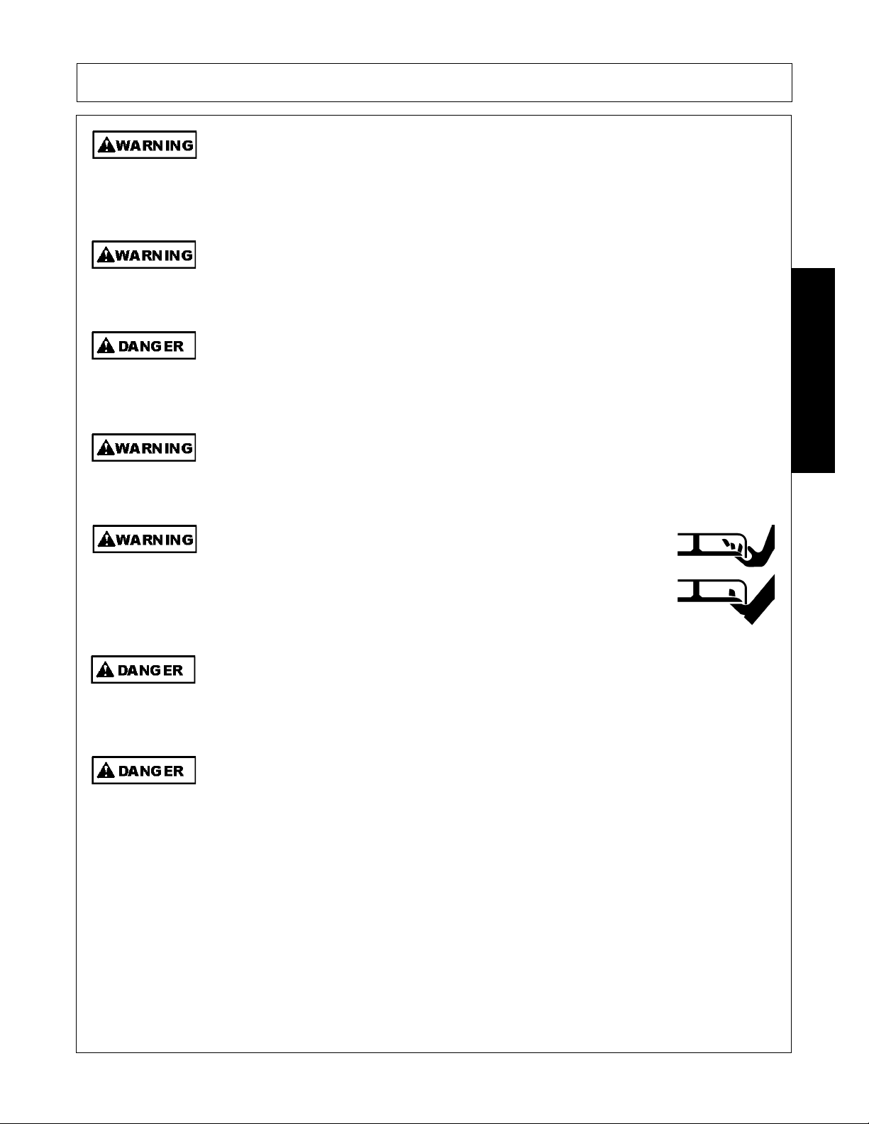
For your protection while operating or servicing equipment, wear relatively tight and belted
clothing to avoid entanglement in moving parts. Tie up and protect long hair that could
become entangled in machinery. Remove all jewelry including necklaces, rings and
watches which can get caught in machinery or on corners or edges of the equipment.
Serious injury can result from entanglement with the machinery.
Operator Safety Instructions and Practices
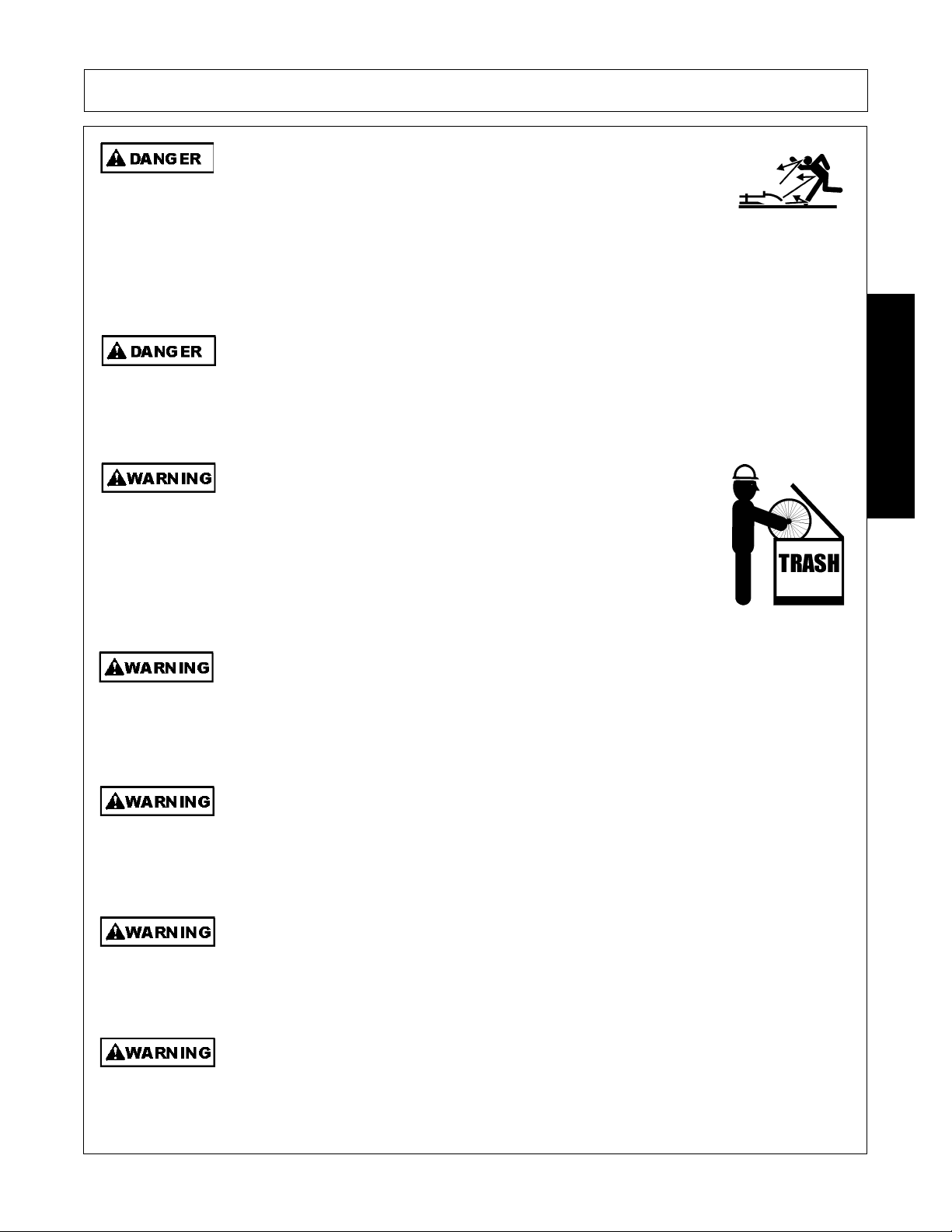
The rotating parts of this machine co ntinue to rot ate even af ter the PT O has been turned of f.
The operator should remain in his seat for 60 seconds after the brake has been set, the
PTO disengaged, the tractor turned off, an d all evidence of rotation has ceased.
“Wait a minute...Save a life!”
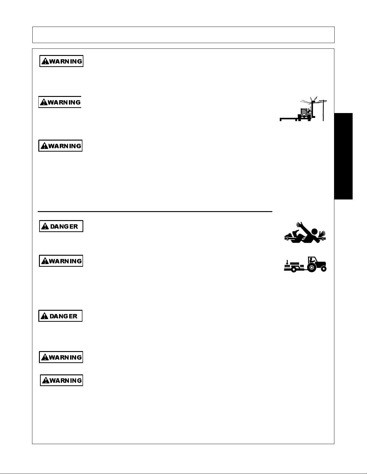
Never crawl under a raised Implement supported solely by the Tractor 3-Point hitch.
Release of the control lever or mechanical failure will result in the Implement falling and
possible injury or death. Always securely block up the Implement before crawling
underneath to perform repairs and service.
ever operate the Tractor or Implement un
completely understand this Manual, the Tractor Operator’s Manual, and
each of the Safety Messages found in the Manual or on the Tractor and
Implement. Learn how to stop the tractor engine suddenly in an
emergency. Never allow inexperienced or untrained personnel to
operate the Tractor and Implement without supervision. Make sure the
operator has fully read and understood the manuals prior to operation.
(SG-4)
(S3PT-19)
SAFETY
(SG-42)
(S3PT-10)
you have read an
The operator and all support personnel should wear hard hats, safety
shoes, safety glasses, and proper hearing protection at all times for
protection from injury including injury from items that may be thrown by
the equipment.
(SG-16)
Eagle 20 03/09 Safety Section 1-3
© 2009 Alamo Group Inc.
Page 12
SAFETY
Al
ith th
Prol
PROLONGED EXPOSURE TO LOUD NOISE MAY CAUSE
PERMANENT HEARING LOSS! Tractors with or without an Implement
attached can often be noisy enough to cause permanent hearing loss.
We recommend that you always wear hearing protection if the noise in
the Operator’s position exceeds 80db. Noise over 85db over an
extended period of time will cause severe hearing loss. Noise over 90db
adjacent to the Operator over an extended period of time will cause
permanent or total hearing loss. NOTE: Hearing loss from loud noise
[from tractors, chain saws, radios, and other such sources close to the
ear] is cumulative over a lifetime without hope of natural recovery.
(SG-I7)
SAFETY
ways read carefully and comply fully w
e manufacturer’s
instructions when handling oil, solvents, cleansers, and any other
chemical agent.
(SG-22)
KEEP AWAY FROM ROTATING ELEMENTS to prevent entanglement
and possible serious injury or death.
(SG-24)
Never allow children to play on or around T ractor o r Implement. Childr en can slip or fall off
the Equipment and be injured or killed. Children can cause the Implement to shift or fall
crushing themselves or others.
(SG-25)
NEVER use drugs or alcohol immediately before or while operating the
Tractor and Implement. Drugs and alcohol will affect an operator’s
alertness and coordination and therefore affect the operator’s ability to
operate the equipment safely. Before operating the Tractor or
Implement, an operator on prescription or over-the-counter medication
must consult a medical professional regarding any side effects of the
medication that would hinder their ability to operate the Equipment safely.
NEVER knowingly allow anyone to operate this equipment when their
alertness or coordination is impaired. Serious injury or death to the
operator or others could result if the operator is under the influence of
drugs or alcohol.
(SG-27)
onged operation may cause operator boredom and fatigue affecting safe operation.
Take scheduled work breaks to help prevent these potentially impaired operating
conditions. Never operate the Implement and Tractor in a fatigued or bored mental state
which impairs proper and safe operation.
Eagle 20 03/09 Safety Section 1-4
© 2009 Alamo Group Inc.
(SG-32)
Page 13
SAFETY
U
tti
d
e
f
se extreme caution when ge
ng onto the Implement to perform repairs, maintenance an
when removing accumulated material. Only stand on solid flat surfaces to ensure good
footing. Use a ladder or raised stand to access high spots which cannot be reached from
ground level. Slipping and falling can cause serious injury or death.
(SG-33)
Avoid contact with hot surfaces including hydraulic oil tanks, pumps, motors, valves and
hose connections. Relieve hydraulic pressure before performing maintenance or repairs.
Use gloves and eye protection when servicing hot components. Contact with a hot surface
or fluid can cause serious injury from burns or scalding.
(SG-34)
DO NOT operate this Implement on a Tractor that is not properly maintained. Should a
mechanical or Tractor control failure occur while operating, immediately shut down the
Tractor and perform repairs before resuming operation. Serious injury and possible death
could occur from not maintaining this Implement and Tractor in good operating condition.
(SG-36)
Avoid contact with hot surfaces of the engine or muffler. Use gloves and eye protection
when servicing hot components. Contact with a hot surface or fluid can cause serious injury
from burns or scalding.
(SG-38)
Do not put hands or feet under mower decks. Blade Contact can result
in serious injury or even death. Stay away until all motion has stopped
and the decks are securely blocked up.
(SGM-09)
SAFETY
Always keep a careful lookout and use extreme care when working around utility and
municipal obstructions. Never allow the Mower to contact any utility, municipal, or other
type structure. Clearly mark all mowing obstructions and consult local utility providers for
a safe code of operation.
(SPU-5)
Do not operate the implement while wearing loose fitting clothing. Entanglement of th
clothing with the rotating elements can result in serious injury or even death. Stay clear o
all rotating elements at all times. (SSP-03)
Eagle 20 03/09 Safety Section 1-5
© 2009 Alamo Group Inc.
Page 14
SAFETY
U
ldi
B
ill b
r
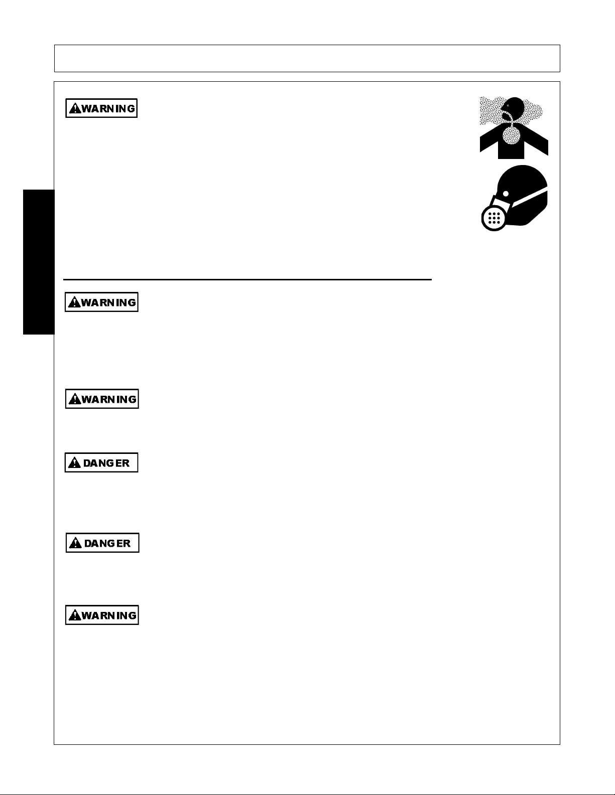
Repeated or substantial breathing of hazardous dusts, including
crystalline silica, could cause fatal or serious respiratory disease including
silicosis. Concrete, masonry, many types of rock, and various other
materials contain silica sand. California lists respirable crystalline silica as
a substance known to cause cancer. Operation of this equipment under
certain conditions may generate airborne dust particles that could contain
crystalline silica. In those conditions, personal protective equipment
including an appropriate respirator must be used. If excessive dust is
generated, a dust collection or suppression system should also be used
during operation.
Equipment Operation Safety Instructions and Practices
(SG-41)
SAFETY
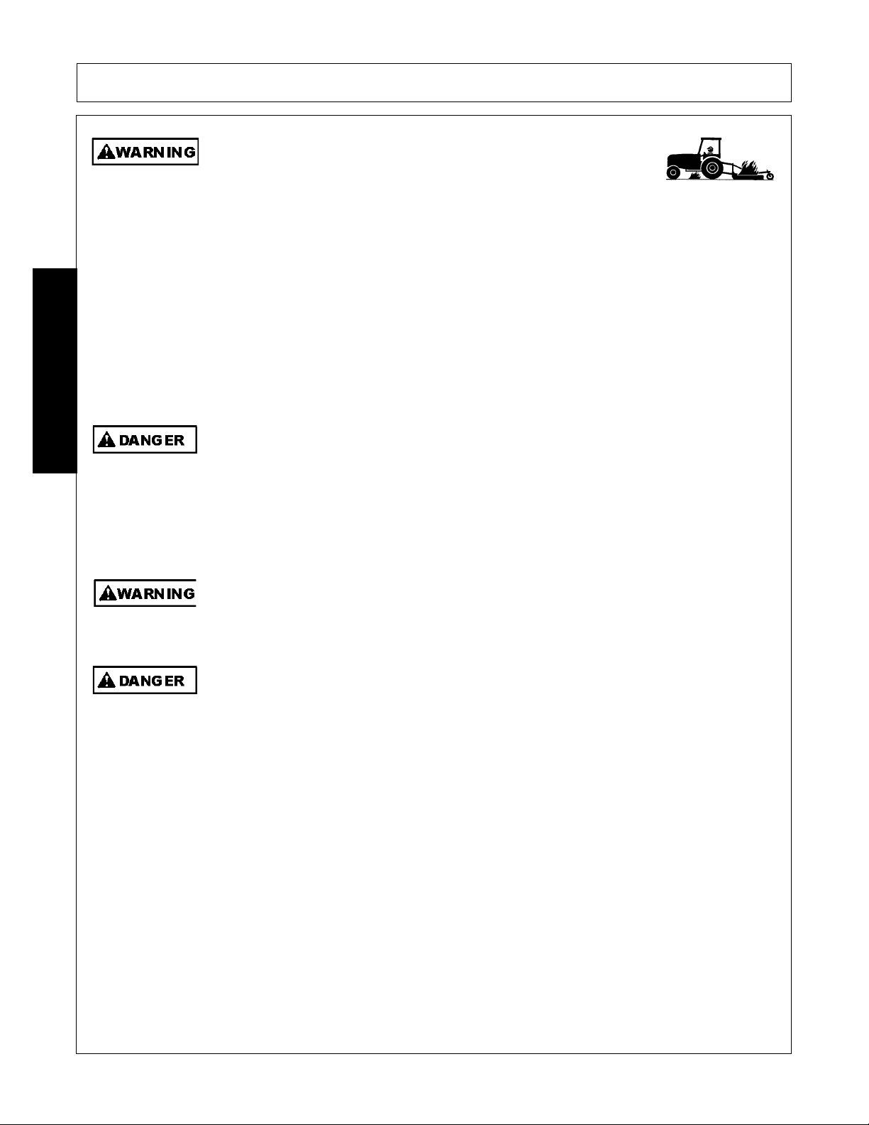
Never leave the Tractor and Implement unattended while the Implement is in the lifted
position. Accidental operation of lifting lever or a hydraulic failure may cause sudden drop
of unit with injury or death by crushing. To properly park the implement when disconnecting
it from the tractor , lower the st and and put the retaining pin securely in place, or pu t a secure
support under the A-Frame. Lower the implement carefully to the ground. Do not put hands
or feet under lifted components .
se extreme care when lowering or unfo
(S3PT-1)
ng the implement’s wings. Make sure no
bystanders are close by or underneath the wings. Allow ample clearance around the
implement when folding or unfolding the wings. Use extreme caution around buildings or
overhead power lines.
(S3PT-05)
This Implement is wider than the Tractor. Be careful wh en operating or transporting this
equipment to prevent the Implement from running into or striking s ign posts, guard rails,
concrete abutments or other solid objects. Such an impact could cause the Implement and
Tractor to pivot violently resulting in loss of steering control, serious injury, or even death.
Never allow the Implement to contact obstacles.
e sure you have adequate knowledge of the property you w
(S3PT-12)
e working on. Take time to
make yourself aware of any area underground lines or cables. Contact with buried lines o
cable could result in serious injury or death. If in doubt about buried utility lines call 811
before digging or 1-800-258-0808.
(SBH-6)
Do not operate Mower if excessive vibration exists. Shut down PTO and the Tractor
engine. Inspect the Mower to determine th e source of the vibration. If Mower blades are
missing or damaged replace them immediately. Do not operate the mower until the
blades have been replaced and the Mower operates smoothly. Operating the Mower with
excessive vibration can result in component failure and broken objects to be thrown
outward at very high velocities. To reduce the possibility of property damage, serious injury ,
or even death, never allow the Mower to be operated with blades missing.
Eagle 20 03/09 Safety Section 1-6
© 2009 Alamo Group Inc.
(SFL-4)
Page 15
SAFETY
Operate this Equipment only with a Tractor equipped with an approved rollover-protective system (ROPS). Always wear seat belts. Serious injury or
even death could result from falling off the tractor--particularly during a turnover
when the operator could be pinned under the ROPS.
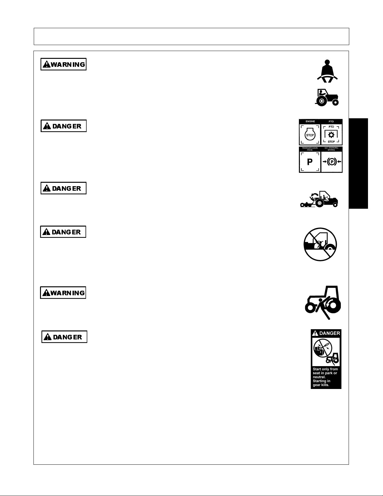
BEFORE leaving the tractor seat, always engage the brake and/or set
the tractor transmission in parking gear, disengage the PTO, stop the
engine, remove the key, and wait for all moving parts to stop. Place the
tractor shift lever into a low range or parking gear to prevent the tractor
from rolling. Never dismount a Tractor that is moving or while the engine
is running. Operate the Tractor controls from the tractor seat only.
Never allow children or other persons to ride on the Tracto r or Implement.
Falling off can result in serious injury or death.
(SG-7)
(SG-9)
(SG-10)
SAFETY
Never allow children to operate, ride on, or come close to the Tractor or
Implement. Usually, 16-17 year-old children who are mature and
responsible can operate the implement with adult supervision, if they
have read and understand the Operator’s Manuals, been trained in
proper operation of the tractor and Implement, and are physically large
enough to reach and operate the controls easily.
(SG-11)
Do not mount or dismount the Tractor while the tractor is moving. Mount
the Tractor only when the Tractor and all moving parts are completely
stopped.
(SG-12)
Start tractor only when properly seated in the Tractor seat. Starting a
tractor in gear can result in injury or death. Read the Tractor operators
manual for proper starting instructions.
(SG-13)
Eagle 20 03/09 Safety Section 1-7
© 2009 Alamo Group Inc.
Page 16
SAFETY
I
difficul
k
SAFETY
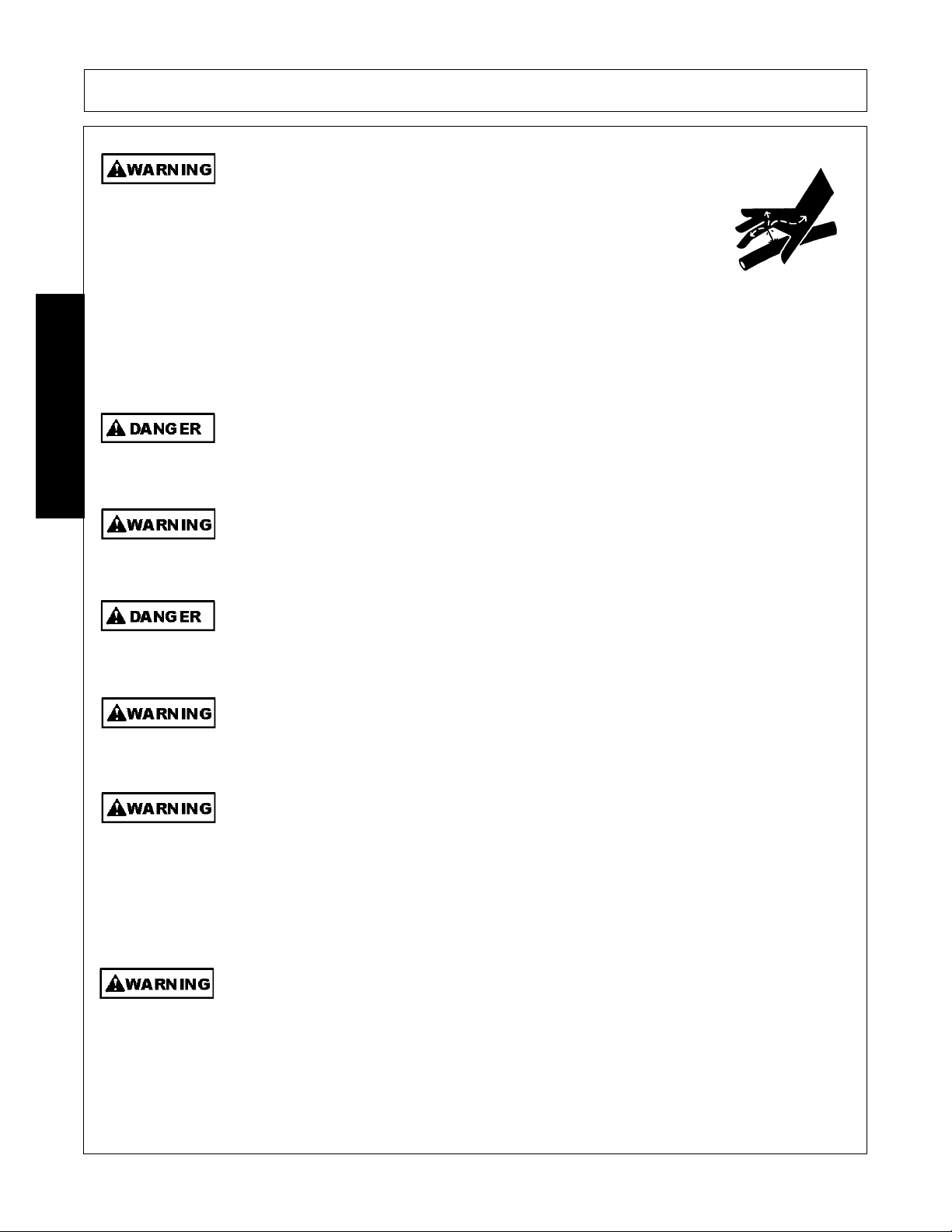
Do not operate this Equipment with hydraulic oil or fuel leaking. Oil
and fuel are explosive and their presence could present a hazard. Do
not check for leaks with your hand! High-pressure oil streams from
breaks in the line could penetrate the skin and cause tissue damage
including gangrene. To check for a hose leak, SHUT the unit ENGINE
OFF and remove all hydraulic pressure. Wear oil imp ene trab le glo ves ,
safety glasses and use Cardboard to check for evidence of oil leaks. If
you suspect a leak, REMOVE the HOSE and have it tested at a Dealer.
If oil does penetrate the skin, have the injury treated immediately by a
physician knowledgeable and skilled in this procedure.
Never run the Tractor engine in a closed building or without adequate ventilation. The
exhaust fumes can be hazardous to your health.
(SG-23)
Do not exceed the rated PTO speed for the Implement. Excessive PTO speeds can cause
Implement driveline or blade failures resulting in serious injury or death.
(SG-15)
(SG-26)
Operate the Tractor and/or Implement control s only while properly seated in the Tractor seat
with the seat belt securely fastened around you. Inadvertent movement of the Tractor or
Implement may cause serious injury or death.
n case of mechanical
ty during operation, place the transmission in the par
(SG-29)
position, set the parking brake, shut down all power, including the PTO and the engine and
remove the key. Wait until all rotating motion has stopped before dismounting.
(SG-39)
Do Not operate this equipment in areas where insects such as bees may attack you and/or
cause you to lose control of th e equipment. If you must enter in such areas, use a tractor
with an enclosed Cab and close the windows to prevent insects from entering. If a tractor
cab is not available, wear suitable clothing including head, face, and hand protection to
shield you from the insects. Attacking insects can cause you to lose control of the tractor,
which can result in serious injury or death to you o r bystanders. Never dismount a moving
tractor.
(SG-40)
Mow only in conditions where you have clear visibility in daylight or with adequate artificial
lighting. Never mow in darkness or foggy conditions where you cannot clearly see at least
100 yards(90 m) in front and to the sides of the tractor and mower. Make sure that you can
clearly see and identify passersby, steep slopes, ditches, drop-offs, overhead obstructions,
power lines, debris and foreign objec ts. If you are unab le to clear ly see thes e type of ite ms
discontinue mowing.
(SGM-1)
Eagle 20 03/09 Safety Section 1-8
© 2009 Alamo Group Inc.
Page 17
SAFETY
Ext
h
M
M
There are obvious and hidden potential hazards in the operation of this
Mower. REMEMBER! This machine is often operated in heavy brush
and in heavy weeds. The Blades of this Mower can throw objects if
shields are not properly installed and maintained. Serious injury or even
death may occur unless care is taken to insure the safety of the operator,
bystanders, or passersby in the area. Do not operate this machine with
anyone in the immediate area. Stop mowing if anyone is within 100 yards
of mower.
(SGM-02)
The rotating parts of this machine have been designed and tested for rugged use.
However, the blades could fail upon impact with heavy, solid objects such as metal guard
rails and concrete structures. Such impact could cause the broken objects to be thrown
outward at very high velocities. To reduce the possibility of property damage, serious
injury, or even death, never allow the cutting blades to contact such obstacles.
(SGM-4)
reme care should be taken when operating near loose objects suc
as gravel, rocks, wire, and other debris. Inspect the area before
mowing. Foreign objects should be removed from the site to prevent
machine damage and/or bodily injury or even death. Any objects that
cannot be removed must be clearly mark ed and car efully avo ide d b y th e
operator. Stop mowing immediately if blades strike a foreign object.
Repair all damage and make certain rotor or blade carrier is balanced
before resuming mowing.
(SGM-05)
any varied objects, such as wire, cable, rope, or chains, can become entangled in the
operating parts of the mower head. These items could then swing outside the housing at
greater velocities than the blades. Such a situation is extremely hazardous and could result
in serious injury or even death. Inspect the cutting area for such objects before mowing.
Remove any like object from the site. Never allow the cutting blades to contact such items.
(SGM-06)
ow at the speed that you can safely operate and control the tractor and mower. The
correct mowing speed depends on terrain condition and grass type, density, and height of
cut. Normal ground speed range is from 2 to 5 mph(3-8 kph). Use slow mowing speeds
when operating on or near steep slopes, ditches, drop-offs, overhead obstructions, power
lines, or when debris and foreign objects are to be avoided.
(SGM-07)
SAFETY
Avoid mowing in reverse direction when possible. Check to make sure there are no
persons behind the mower and use extreme care when mowing in reverse. Mow only at a
slow ground speed where you can safely operate and control the tractor and mower.
Never mow an area that you have not inspected and removed debris or foreign material.
(SGM-08)
Do not mow with two machines in the same area except with Cab tractors with the windows
closed.
(SGM-11)
Eagle 20 03/09 Safety Section 1-9
© 2009 Alamo Group Inc.
Page 18
SAFETY
The M
ifi
Follow these guidelines to reduce the risk of equipment and grass fires
while operating, servicing, and repairing the Mower and Tractor:
-Equip the Tractor with a fire extinguisher in an accesible location.
-Do Not operate the Mower on a Tractor with an underframe exhaust.
-Do Not smoke or have an open flame near the Mower and Tractor.
-Do Not drive into burning debris or freshly burnt area s.
-Ensure slip clutches are properly adjusted to prevent excessive slippage and plate heating.
-Never allow clippings or debris to collect near drivelines, slip clutches, and gearboxes.
Periodically shut down the T ractor an d Mo we r and cl ean clip pin gs and collected deb ris from
the mower deck.
(SGM-12)
SAFETY
ower is designed for certain mowing applications and is rated to cut up to a spec
size vegetation (see Mower Standard Equipment and Specifications). DO NOT use this
mower to cut vegetation above the Mower’s rated capacity or to cut any type of nonvegetative material. Only operate this Mower on a properly sized and equipped Tractor.
Operating this Mower in an application for which it is not designed and/or operating the
Mower with the wrong size Tractor can cause Mower component damage and equipment
failure resulting in possible serious injury or death.
Do not operate or pull the mower into standing water. When uplift or fan type mower blades
contact water they can be severely deflected downward causing possible failure of blade
resulting in serious boldly injury to the operator or by standers.
Use extreme caution when raising the Mower above ground level. Stop the Blades from
turning when the Mower is raised and passersby are within 100 yards. Raising the
Mower exposes the Cutting Blades which creates a potentially serious hazard and can
cause serious injury by objects thrown from the Blades or by contact with the Blades.
(SGM-14)
(SGM-15)
(SPU-1)
c
Eagle 20 03/09 Safety Section 1-10
© 2009 Alamo Group Inc.
Page 19
SAFETY
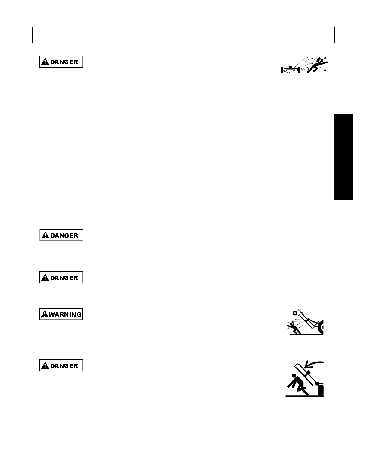
Rotary Mowers are capable under adverse conditions of throwing
objects for great distances (300 feet or more) and causing serious injury
or death. Follow safety messages carefully.
STOP MOWING IF PASSERSBY ARE WITHIN 100 YARDS UNLESS:
-Front and Rear Deflectors, Chain Guards, or Bands are installed and in good, workable
condition;
-Mower sections or Wings are running close to and parallel to the ground without exposed
Blades;
-Passersby are outside the existing thrown-object zone;
-All areas have been thoroughly inspected and all foreign material such as rocks, cans,
glass, and general debris has been removed.
NOTE: Where there are grass and weeds high enough to hide debris that could be struck
by the blades, the area should be: inspected and large debris removed, mowed at an
intermediate height, inspected, closely with any remaining debris being removed, and
mowed again at desired final height. (This will also reduce power required to mow, reduce
wear and tear on the Mower drivetrain, spread cut material better, reduce streaking, and
make the final cut more uniform).
(SRM-01)
Do Not attempt to raise or lower the implement wing unless the Implement tongue is
securely attached to the Tractor drawbar. The Implement could tip over and cause
equipment damage and possible s erious injury or death. Raise or Lo wer the mower wing
only while seated in the Tractor operator’s seat with the seat be lt securely fastened.
Do not turn so sharp or lift mower so high to produce a severe "knocking" of the Driveline
which will cause accelerated wear and breakage of drive train components and could result
in possible injury from the separated Driveline sections.
(SRM-04)
SAFETY
(SRM-2)
Do not let the Blades turn when the Mower Deck is raised for any
reason, including clearance or for turning. Raising the Mower deck
exposes the Cutting Blades which creates a potentially serious hazard
and could cause serious injury or even death from objects thrown from
the Blades.
(SRM-07)
DO NOT allow any person under a folded wing unless wing is securely
locked up or supported. DO NOT approach the Implement unless the
Tractor is turned off and all motion has ceased. Never work under the
frame work, or any lifted component unless the implement is securely
supported or blocked up. A sudden or inadvertent fall by any of these
components could cause serious injury or even death.
Eagle 20 03/09 Safety Section 1-11
© 2009 Alamo Group Inc.
(STI-03)
Page 20
SAFETY
Wh
PTO, it is i
Connecting or Disconnecting Implement Safety Instructions and Practices
DO NOT use a PTO adapter to attach a non-matching Implement driveline to a Tractor
PTO. Use of an adapter can double the operating speed of the Implement resulting in
excessive vibration, thrown objects, and blade and implement failure. Adapter use will also
change the working length of the driveline exposing unshielded driveline areas. Serious
bodily injury and/or equipment failure can result from using a PTO adapter. Consult an
authorized dealer for assistance if the Implement driveline does not match the Tractor PTO.
(S3PT-14)
Always shut the Tractor completely down, place the transmission in park, and set the
parking brake before you or anyone else attempts to connect or disconnect the Implement
and Tractor hitches.
(S3PT-15)
SAFETY
en attaching the Implement input driveline to the Tractor
connecting yoke spring activated locking collar slides freely and the locking balls are seated
securely in the groove on the Tractor PTO shaft. Push and pull the driveline back and forth
several times to ensure it is securely attached. A driveline not attached correctly to the
Tractor PTO shaft could come loose and result in personal injury and damage to the
Implement.
(S3PT-17)
mportant that the
Before operating the Implement, check to make sure the Implement input driveline will not
bottom out or become disengaged. Bottoming out occurs when the inner shaft penetrates
the outer housing until the assembly be comes solid -it can shorte n no more. Bott oming out
can cause serious damage to the Tractor PTO by pushing the PTO into the Tractor and
through the support bearings or downward onto the PTO shaft, breaking it off. A broken
driveline can cause personal injury.
Never unhitch without using the Tongue Jack. The Tongue is very heavy. Attempting to lift
the Tongue without using the Tongue Jack could cause strains or other injury. Allowing the
tongue to fall suddenly and unexpectedly could result in crushing injury. Use the Tongue
Jack for lifting the Implement only. Overloading the Tongue Jack can cause failure with
possible serious bodily injury or even death.
On a fully-assembled unit, do not remove the Wing Retaining Strap until hoses are attached
to the tractor and the Wing Cylinders are filled with oil. Lower the Wings slowly and
carefully. Keep bystanders away during operations.
(S3PT-18)
(STI-04)
(STI-05)
Eagle 20 03/09 Safety Section 1-12
© 2009 Alamo Group Inc.
Page 21
SAFETY
r
Transporting Safety Instructions and Practices
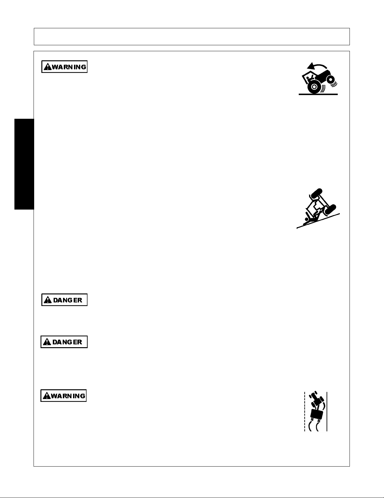
Be particularly careful when transporting the Implement with the Tractor. Turn curves or go
up hills only at a low speed and using a gradual steering angle. Rear mounted implements
move the center of gravity to the rear and remove weight from the front wheels. Make
certain, by adding front ballast, that at least 20 % of the tractor’s weight is on the front wheels
to prevent rearing up, loss of steering control or Tractor tip-over. Slow down on rough o
uneven surfaces to prevent loss o f steering control which could result in property damage
or possible injury. Do not transport unless 3-Point lift lever is fully raised and in the latched
transport position. Dropping implement in transport can cause serious damage to the
tractor and/or Implement and possibly cause the operator or others to be injured or killed.
(S3PT-02)
Allow sufficient clearance for the Implement to swing outward while turning. Implements
carried behind the Tractor will swing outside the tire path when making turns. Contacting a
solid object while turning will cause equipment damage and possible injury.
Make certain that the “Slow Moving Vehicle” (SMV) sign is installed in
such a way as to be cl early visible and legible. When transport ing the
Equipment use the Tractor flashing warning lights and follow all local
traffic regulations.
(SG-6)
SAFETY
(S3PT-20)
Eagle 20 03/09 Safety Section 1-13
© 2009 Alamo Group Inc.
Page 22
SAFETY
B
Only t
Transport only at speeds where you can maintain control of the
equipment. Serious accidents and injuries can result from operating this
equipment at high speeds. Understand the Tractor and Implement and
how it handles before transporting on streets and highways. Make sure the Tractor steering
and brakes are in good condition and operate properly.
Before transporting the Tractor and Implement, determine the proper transport speeds for
you and the equipment. Make sure you abide by the following rules:
Test the tractor at a slow speed and increase the speed slowly. Apply the Brakes smoothly
to determine the stopping characteristics of the Tractor and Implement. As you increase
the speed of the Tractor the stopping distance increases. Determine the maximum
transport speed not to exceed 20 mph (30 kph) for transporting this equipment.
Test the equipment at a slow speed in turns. Increase the speed through the turn only after
you determine that the equipment can be operated at a higher speed. Use extreme care
and reduce your speed when turning sharply to prevent the tractor and implement from
turning over. Determine the maximum turning speed for you and this equipment before
SAFETY
operating on roads or uneven ground.
Only transport the Tractor and Implement at the speeds which allow you to properly control
the equipment.
Be aware of the operating conditions. Do not operate the Tractor with weak or faulty brakes
or worn tires. When operating down a hill or on wet or rain slick roads, the braking distance
increases: use extreme care and reduce you r speed. When operating in traffic always use
the Tractor’s flashing warning lights and red uce your speed. Be a ware of traf fic around yo u
and watch out for the other guy.
(SG-19)
e particularly careful when transporting the Implement using the tractor. Turn curves or
go up or down hills only at a low speed and at a gradual steering angle. Make certain that
at least 20% of the tractor’s weight is on the front wheels to maintain safe steerage. Slow
down on rough or uneven surfaces.
When the Wings are folded for transport, the center of gravity is raised and the possibility of
overturn is increased. Drive slowly and use extreme caution when turning on hillsides.
Overturning the Implement could cause the Implement to overturn the Tractor and vice
versa resulting in serious injury or even death. Never fold wings on a hillside...the
Implement may overturn.
ow the Implement behind a properly sized and equipped Tractor
which exceeds the weight of the Implement by at least 20%. DO NOT
tow the Implement behind a truc k or ot her t ype o f vehic le. N ever tow the
Implement and another Implement connected in tandem. Never tow the
Implement at speeds over 20 MPH.
Eagle 20 03/09 Safety Section 1-14
© 2009 Alamo Group Inc.
(STI-02)
(STI-01)
(STI-06)
Page 23
SAFETY
Secure the Implement for transport before traveling on public roads. For pull-type
Implements, secure the center axle u sing cylinder stop s or transpo rt pin and prop erly att ach
a safety chain between the Implement and Tractor. Secure wings in upright position on
folding Implements using wing transport locks.
Always keep a careful lookout and use extreme care when working
around overhead obstructions and electrical power lines. The
Implement wing can be over 10 feet high. Never allow the Implement
wing to come within 10 feet of any power line.
Your driving vision may be reduced or impaired by the tractor, cab, or implement. Before
driving on public roadways identify any limited vision areas, and make adjustments to your
operating position, mirrors, and the implement transport position so that you can clearly
see the area where you will be traveling, and any traffic that may approach you. Failure to
maintain adequate vision of the public roadway and traffic can result in serious injury or
even death.
(STI-10)
Maintenance and Service Safety Instructions and Practices
(STI-7)
(STI-8)
SAFETY
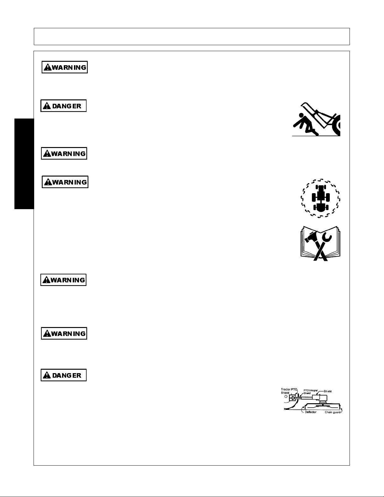
Make sure the PTO shield, integral driveline shields, and input shields
are is installed when using PTO-driven equipment. Always replace any
shield if it is damaged or missing.
(S3PT-8)
Relieve hydraulic pressure prior to doing any maintenance or repair work
on the Implement. Place the Implement on the ground or securely
blocked up, disengage the PTO, and turn off the tractor engine. Push
and pull the Remote Cylinder lever in and out several times prior to
starting any maintenance or repair work.
(S3PT-09)
Always disconnect the main PTO Driveline from the Tractor before performing service on
the Implement. Never work on the Implement with the tractor PT O dr iveline conn ected and
running. Rotating Parts, Blades or Drivelines could turn without warning and cause
immediate entanglement, injury or death.
(S3PT-11)
Never interfere with factory-set hydraulic calibrations. Any change in calibration could
cause a failure of the equipment and may result in injury.
(SBH-13)
Always maintain the safety signs in good readable condition. If th e safety signs are missing,
damaged, or unreadable, obtain and install replacement safety signs immediately.
(SG-5)
Eagle 20 03/09 Safety Section 1-15
© 2009 Alamo Group Inc.
Page 24
SAFETY
U
dli
SAFETY
Do not modify or alter this Implement. Do not permit anyone to modify or alter this
Implement, any of its components or any Implement function.
Never work under the Implement, the framework, or any lifted
component unless the Implement is securely supported or blocked up
to prevent sudden or inadvertent falling which could cause serious
injury or even death.
(SG-14)
Never attempt to lubricate, adjust, or remove material from the Implement while it is in
motion or while tractor engine is running.
(SG-20)
Periodically inspect all moving parts for wear and replace when
necessary with authorized service parts. Look for loose fasteners, worn
or broken parts, and leaky or loose fittings. Make sure all pins have
cotter pins and washers. Serious injury may occur from not maintaining
this machine in good working order.
(SG-21)
(SG-8)
Perform service, repairs and lubrication according to the maintenance section. Ensure the
unit is properly lubricated as specified in the lubrication schedule and all bolts and nuts are
properly torqued. Failure to properly servic e, repair and maintain this Implement in good
operating condition could cause component failure and possible serious injury or even
death.
(SG-35)
se caution and wear protective gloves when han
ng sharp objects such as blades,
knives, and other cutting edges. Be alert to worn component surfaces which have sharp
edges. Sharp surfaces can inflict severe laceration injuries if proper hand protection is not
worn.
(SG-37)
All Safety Shields, Guards and Safety devices including (but not
limited to) - the Deflectors, Chain Guards, Steel Guards, Gearbox
Shields, PTO integral shields, and Retractable Door Shields should
be used and maintained in good working condition. All safety
devices should be inspected carefully at least daily for missing or
broken components. Missing, broken, or worn items must be
replaced at once to reduce the possibility of injury or death from
thrown objects, entanglement, or blade cont act.
(SGM-3)
Eagle 20 03/09 Safety Section 1-16
© 2009 Alamo Group Inc.
Page 25

SAFETY
B
ill b
I
diti
likelihood of
Replace bent or broken blades with new blades. NEVER ATTEMPT TO STRAIGHTEN,
WELD, OR WELD HARDFACING ON BLADES SINCE THIS WILL LIKELY CRACK OR
OTHERWISE DAMAGE THE BLADE WITH SUBSEQUENT FAILURE AND POSSIBLE
SERIOUS INJURY FROM THROWN BLADES.
DO NOT weld or repair rotating mower components. Welds and other repairs may cause
severe vibration and/or component failure resulting in part being thrown from the mower
causing serious bodily injury. See your Authorized Dealer for proper repairs.
(SGM-10)
(SGM-13)
PARTS INFORMATION
Alamo Industrial mowers use balanced and matched system components for blade carriers, blades,
cuttershafts, knives, knife hangers, rollers, drivetrain components, and bearings. These parts are made and
tested to Alamo Industrial specifications. Non-genuine "will fit" parts do not consistently meet these
specifications. The use of “will fit” parts may reduce mower performance, void mower warranties, and present
a safety hazard. Use genuine Alamo Industrial mower parts for economy and safety.
(SPRM-1)
SEE YOUR ALAMO DEALER
e sure you have adequate knowledge of the property you w
e working on. Take time to
make yourself aware of any area underground lines or cables. Contact with buried lines
or cable could result in serious injury or death.
n wet con
ons where there is a
certain that this material is removed before traveling on public roadways.
(STL-1)
material collecting on the Implement, make
(STL-7)
Storage and Parking Safety Instructions and Practices
To prevent tipping of Implement when stored in folded position, use carrying wheels or
adequate stands on center frame.
(S3PT-6)
Concluding Safety Instructions and Practices
SAFETY
In addition to the design and configuration of this Implement, including Safety Signs and Safety Equipment,
hazard control and accident prevention are dependent upon the awareness, concern, prudence, and proper
training of personnel involved in the operation, transport, maintenance, and storage of the machine. Refer
also to Safety Messages and operation instruction in each of the appropriate sections of the Tractor and
Equipment Manuals. Pay close attention to the Safety Signs affixed to the Tractor and Equipment.
(SG-18)
Eagle 20 03/09 Safety Section 1-17
© 2009 Alamo Group Inc.
Page 26
SAFETY
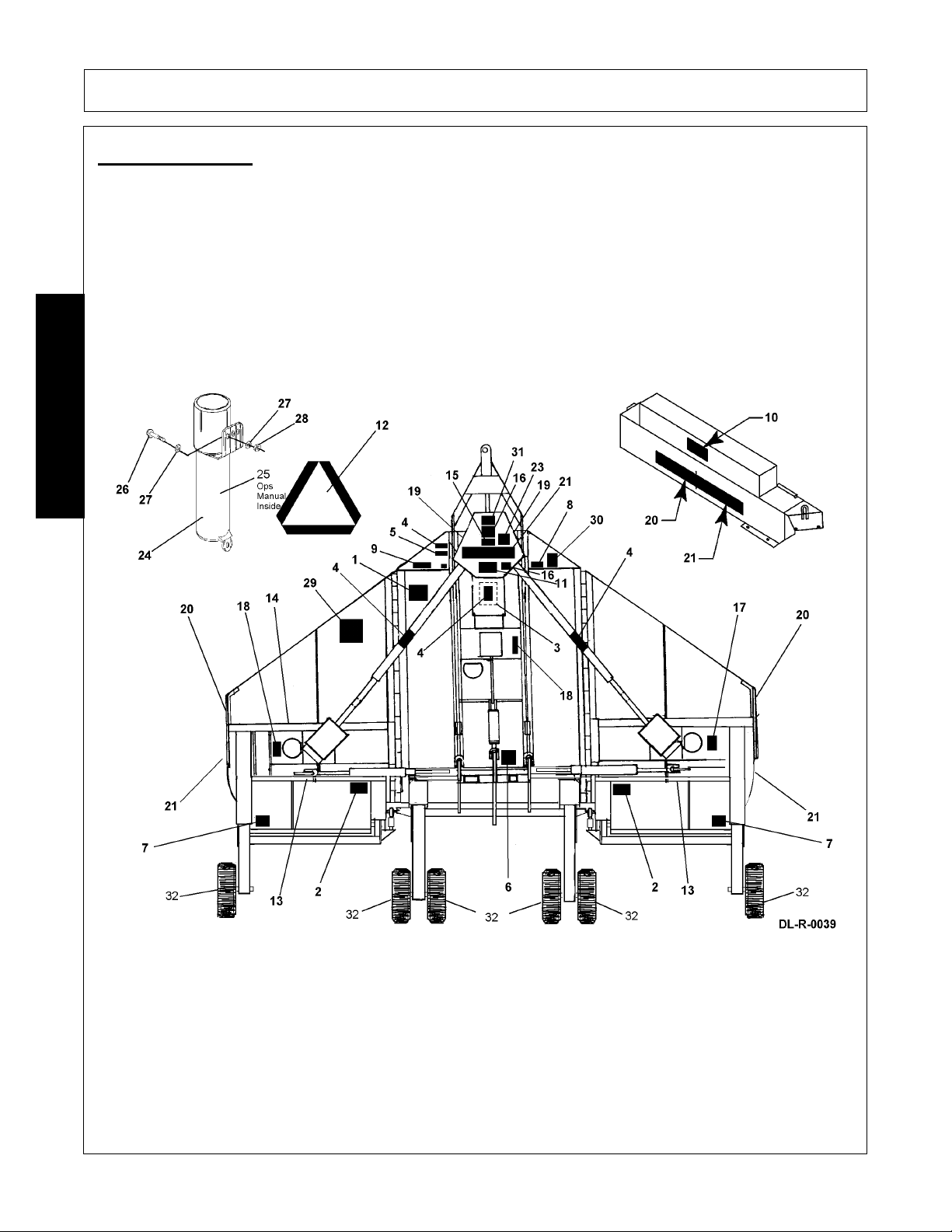
Decal Location
NOTE: Alamo Industrial supplies safety decals on this product to promote safe operation. Damage to the
decals may occur while in shipping, use, or reconditioning. Alamo Industrial cares about the safety of its
customers, operators, and bystanders, and will replace the safety decals on this product in the field, free of
charge (Some shipping and handling charges may apply). Contact your Alamo Industrial dealer to order
replacement decals.
SAFETY
Eagle 20 03/09 Safety Section 1-18
© 2009 Alamo Group Inc.
Page 27

SAFETY
ITEM PART NO. QTY TYPE DESCRIPTION
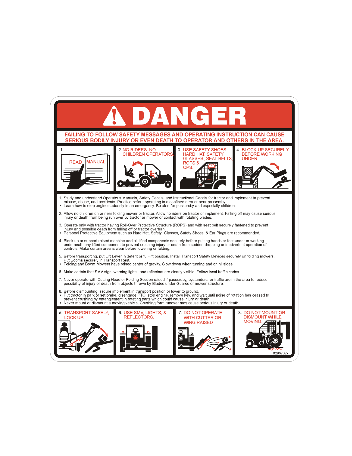
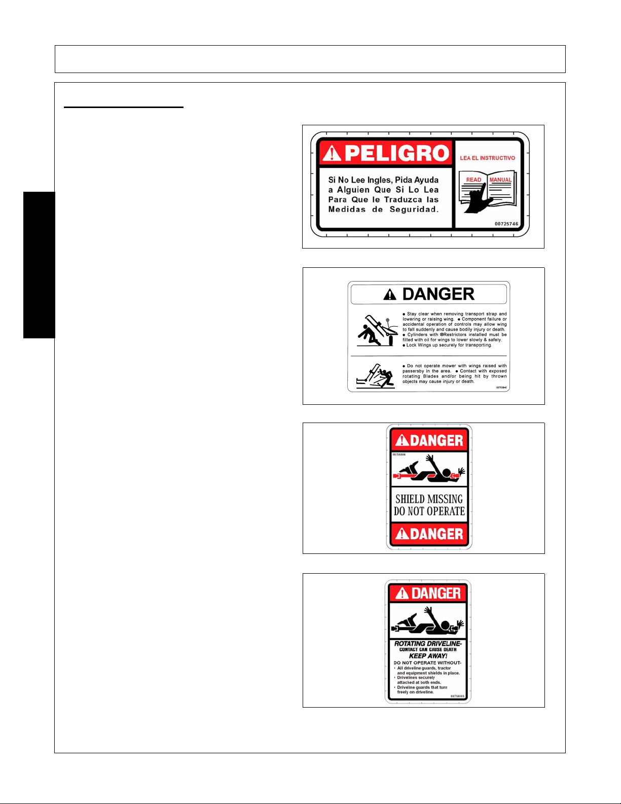
1. 00725746 1 PELIGRO Get Manual Translated
2. 00753840 2{1} DANGER Folding Wings
3. 00756004 ((3{1})) DANGER Driveline Shield Missing
4. 00756005 3{1} DANGER Rotating Driveline
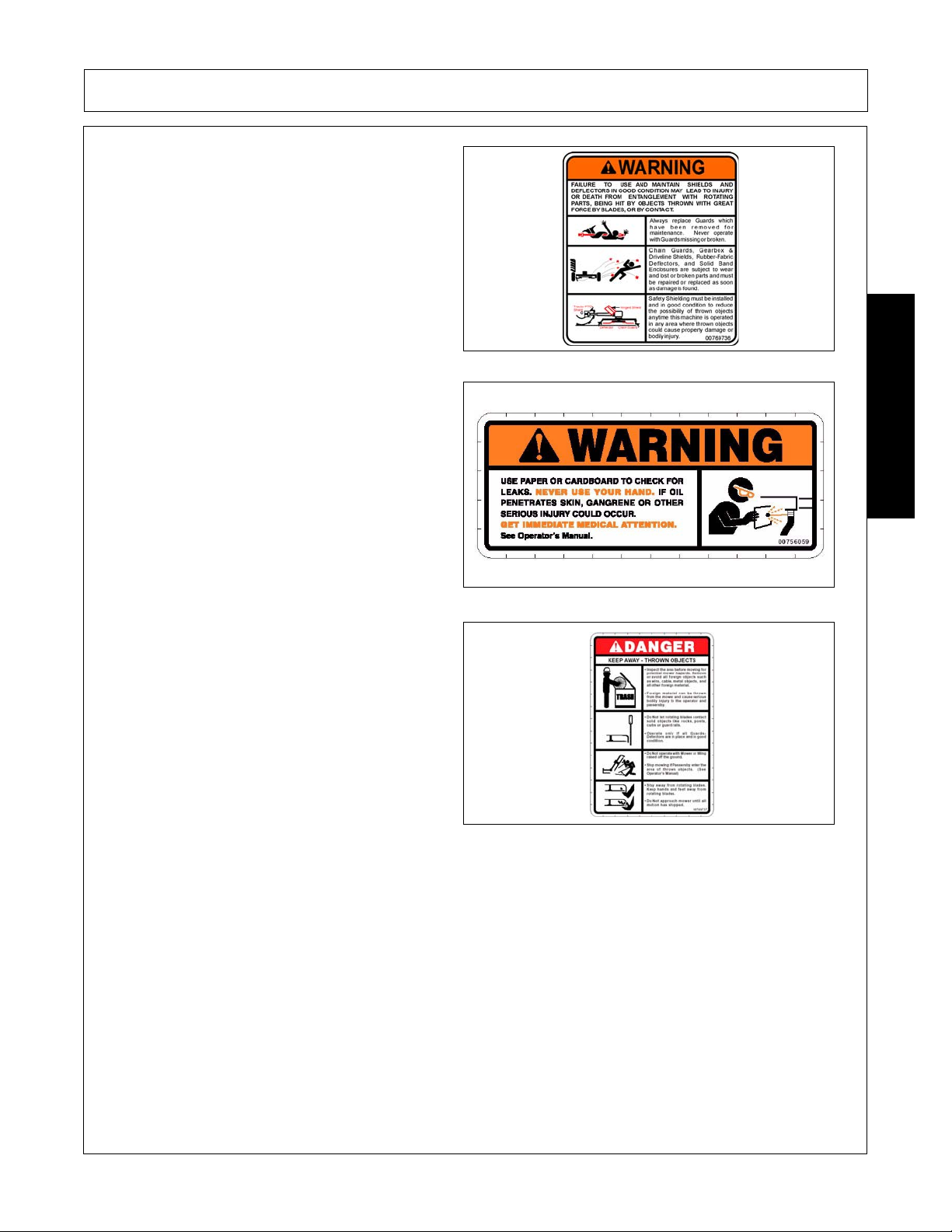
5. 00769736 1 WARNING Use/Repair Shields & Guards
6. 00756059 1 WARNING Leak Detection
7. 00769737 2{1} DANGER Cutting Blades Thrown Objects
8. 00756494 1 DANGER Driveline Hazards
9. 02925100 1 IMPORTANT Genuine Parts, Rotary
10. 999043 0{1} DANGER Overturn of Two-Section Flex
11. D103 [1] INSTRUCT 540 RPM D114 [1] INSTRUCT 1000 RPM PTO
12. 03200347 * REFLECT SMV
13. 1458392 2 REFLECT Red Reflector
14. 1458393 1 REFLECT Amber Reflector
15. 00763977 1 INSTRUCT Notice to Owner
16. D102 1 INSTRUCT PTO to Drawbar Hole Adj.
17. D137 1 INSTRUCT CCW Blade Rotation
18. D138 2{1} INSTRUCT CW Blade Roation
19. 02960766 2 LOGO Alamo Industrial
20. 02977139 2 L.NAME Alamo Industrial
21. [3] NAME Eagle 20
------------- [3] NAME Eagle 14
22. nfs 1 SER PLATE Eagle 20/14 Serial Plate
23. 00771283 1 INSTRUCT 5 Year Gearbox Warranty
24. 00776031 1 Canister, Operator’s Manual
25. 00778645C 1 Operator’s Manual
26. 10058000 3 Bolt
27. 00024100 6 Flatwasher
28. 02959924 3 Locknut
29. 00749117 1 DANGER Multi-Hazard
30. 00773723 1 PELIGRO Rotating Driveline Translation
31. 00777394 1 WARNING TRANSPORT
32. 1006348 6** WARNING Tire Explosion Hazard
33. D482 1* WARNING Jack Positioning
SAFETY
{ }Quantities for 14’ unit Only (( )) Installed by Driveline Manufacturer
[ ] Use one or the other ** Provided by Wheel Supplier
* Provided by Jack Manufacturer
Decal Sheets
Center Section 00778873
Divider Gearbox 00778871
Left & Right Wing 00778872
Eagle 20 03/09 Safety Section 1-19
© 2009 Alamo Group Inc.
Page 28
Decal Description
Peligro Translation, If you do not know how to read
English, please find someone who knows how to
read English.
P/N 00725746
DANGER! Stay clear when lowering or raising
wings.
SAFETY
SAFETY
P/N 00753840
DANGER! Guard Missing, Do Not Operate. If you
see this decal, Do Not Operate the mower until the
shield has been replaced.
P/N 00756004
DANGER! Rotating Driveline Keep Away, Contact
can cause death.
P/N 00756005
Eagle 20 03/09 Safety Section 1-20
© 2009 Alamo Group Inc.
Page 29
SAFETY
WARNING! Maintain shields and deflectors in
good condition. Failure to do so may lead to injury
or even death.
P/N 00769736
WARNING! Never use your hand to check for oil
leaks. Always use paper or cardboard.
P/N 00756059
DANGER! Keep Away Thrown Objects.
Inspect the area before mowing for potential mower
hazards. Remove or avoid all foreign objects such
as wire, cable, metal objects, and all other foreign
material.
Foreign material can be thrown from the mower
and cause serious bodily injury to the operator and
passerby.
SAFETY
Do Not let rotating blades contact solid objects like
rocks, posts, curbs or guard rails.
Operate only if all Guards, Deflectors are in place
and in good condition.
Do Not operate with Mower or Wing raised off the
ground.
Stop mowing if Passersby enter the area of thrown
objects. (See Operator’s Manual)
P/N 00769737
Eagle 20 03/09 Safety Section 1-21
© 2009 Alamo Group Inc.
Page 30
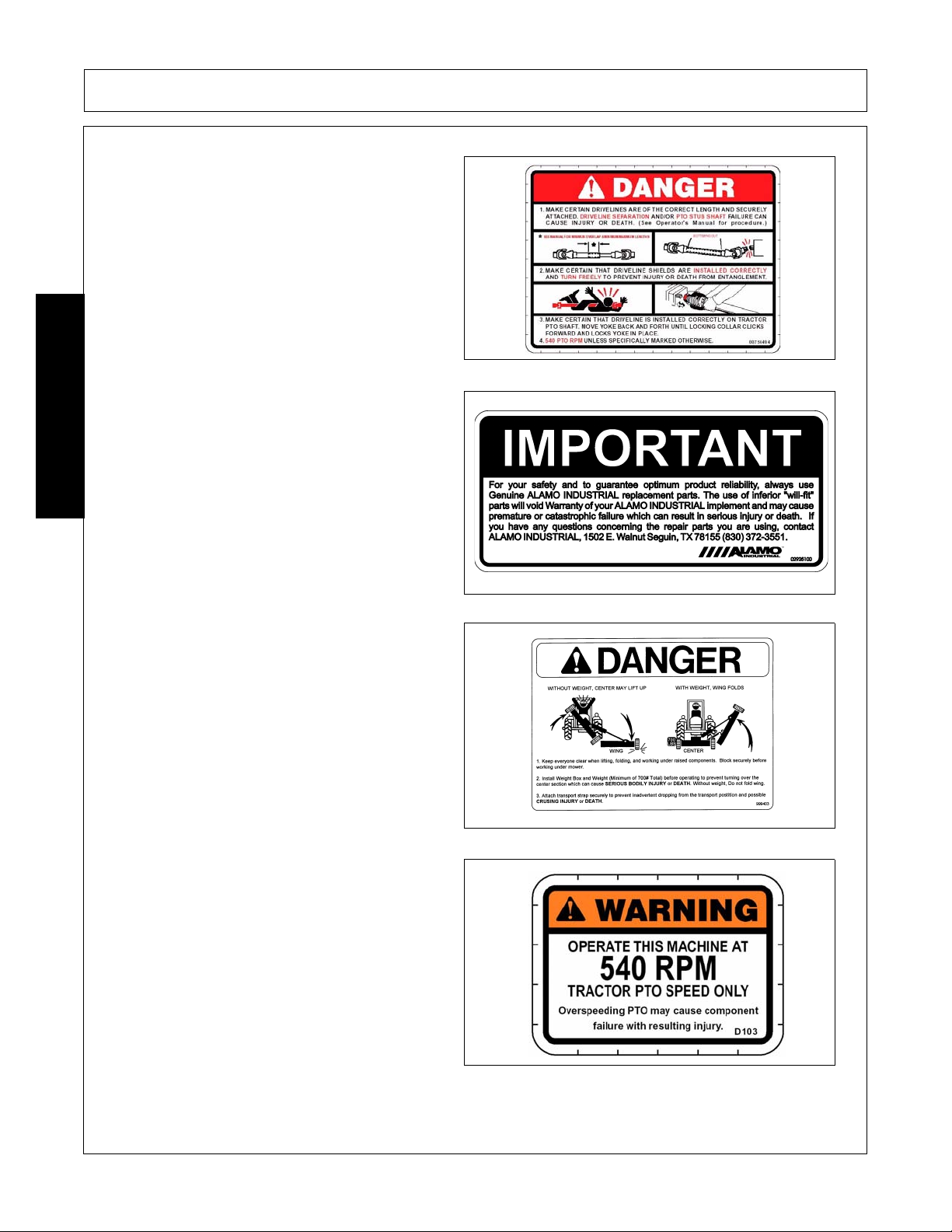
DANGER! Make certain that drivelines are correct
length and are securely attached.
P/N 00756494
IMPORTANT - Use only Genuine Alamo Industrial
replacement parts.
SAFETY
SAFETY
P/N 02925100
DANGER! Keep everyone clear when lifting,
folding, and working under raised components.
Block securely before working under mower. Install
Weight Box and Weight (Min. of 700lbs) before
operating to prevent turning o ver t he ce nter section
which can cause SERIOUS BODILY INJURY or
DEATH. Without weight, Do not fold wing. Attach
transport strap securely to prevent inadvertent
dropping from the transport position and possible
CRUSHING INJURY OR DEATH.
P/N 999403
WARNING! Avoid Bodily Injury, Use 540RPM PTO
Speed Only.
P/N D103
Eagle 20 03/09 Safety Section 1-22
© 2009 Alamo Group Inc.
Page 31

SAFETY
WARNING! Avoid Bodily Injury, Use 1000 RPM
PTO Speed Only.
P/N D114
Slow Moving Vehicle Decal. Keep SMV reflector
clean and visible. DO NOT transport or operate
without the SMV.
P/N 03200347
Red Reflector. Keep reflectors clean and visible.
SAFETY
P/N 1458392
Amber Reflector. Keep reflectors clean and visible.
P/N 1458393
Eagle 20 03/09 Safety Section 1-23
© 2009 Alamo Group Inc.
Page 32

Operator's Manual (with repair parts) and warranty
was attached to this implement during final
inspection.
P/N 00763977
IMPORTANT! Required For Jackshaft Unit.
Suggested for standard shaft.
SAFETY
SAFETY
P/N D102
Blade Rotation Counter Clockwise.
P/N D137
Blade Rotation Clockwise.
P/N D138
Eagle 20 03/09 Safety Section 1-24
© 2009 Alamo Group Inc.
Page 33

NAME LOGO - Alamo Industrial
SAFETY
P/N 02960766
Name LOGO - Alamo Industrial
P/N 00757139
NAME LOGO - EAGLE 20
SAFETY
EAGLE 20
NAME LOGO - EAGLE 14
EAGLE 14
Eagle 20 03/09 Safety Section 1-25
© 2009 Alamo Group Inc.
Page 34

INFORMATION - 5 Year Gearbox Warranty
P/N 00771283
Read Operator’s Manual! The operator’s manual is
located inside this canister. If the manual is
missing order one from your dealer.
SAFETY
SAFETY
P/N 00776031
Eagle 20 03/09 Safety Section 1-26
© 2009 Alamo Group Inc.
Page 35

Multi Hazard Decal Sheet
SAFETY
P/N 00749117
SAFETY
Eagle 20 03/09 Safety Section 1-27
© 2009 Alamo Group Inc.
Page 36

PELIGRO! Spanish Translation for Driveline Safety
P/N 00773723
WARNING! DO NOT transport at speeds higher
than 20 mph. Only transport behind a properly
sized and equipped tractor.
SAFETY
SAFETY
P/N 00777394
WARNING! Explosion Hazard - Release all air
pressure in tire before loosening bolts.
P/N 1006348
WARNING! Jack - Maximum Capacity 3,200 lbs.
Side Load 2,000 lbs.
P/N D482
Eagle 20 03/09 Safety Section 1-28
© 2009 Alamo Group Inc.
Page 37

SAFETY
Federal Laws and Regulations
This section is intended to explain in broad term s the concept and effect of federal laws and regulations
concerning employer and employee equipment operators. This section is not intended as a legal
interpretation of the law and should not be considered as such.
Employer-Employee Operator Regulations
U.S. Public Law 91-596 (The Williams-Steiger Occupational and Health Act of 1970) OSHA
This Act Seeks:
“...to assure so far as possible every working man and woman in the nation safe and healthful working
conditions and to preserve our human resources...”
DUTIES
Sec. 5 (a) Each employer(1) shall furnish to each of his employees employment and a place of employment which are free from
recognized hazards that are causing or are likely to cause death or serious physical harm to his employees;
(2) shall comply with occupational safety and health standards promulgated under this Act.
(b) Each employee shall comply with occupational safety and health standards and all rules, regulations and
orders issued pursuant to this Act which are applicable to his own actions and conduct.
OSHA Regulations
OSHA regulations state in part: “At the time of initial assignment and at least annually thereafter, the employer
shall instruct every employee in the safe operation and servicing of all equipment with which the employee is,
or will be involved.”
Employer Responsibilities:
SAFETY
To ensure employee safety during Tractor and Implement operation, it is the employer’s responsibility to:
1. Train the employee in the proper and safe operation of the Tractor and Implement.
2. Require that the employee read and fully understand the Tractor and Implement Operator’s manual.
3. Permit only qualified and properly trained employees to operate the Tractor and Implement.
4. Maintain the Tractor and Implement in a safe operational condition and maintain all shields and guards on the
equipment.
5. Ensure the Tractor is equipped with a functional ROPS and seat belt and require that the employee ope rator
securely fasten the safety belt and operate with the ROPS in the raised position at all times.
6. Forbid the employee operator to carry additional riders on the Tractor or Implement.
7. Provide the required tools to maintain the Tractor and Implement in a good safe working condition and provide the
necessary support devices to secure the equipment safely while performing repairs and service.
8. Require that the employee operator stop operation if bystanders or passersby come within 25 feet.
Child Labor Under 16 Years of Age
Some regulations specify that no one under the age of 16 may operate power machinery. It is your
responsibility to know what these regulations are in your own area or situation. (Refer to U.S. Dept. of
Labor, Employment Standard Administration, Wage & Home Division, Child Labor Bulletin #102.)
Eagle 20 03/09 Safety Section 1-29
© 2009 Alamo Group Inc.
Page 38

Page 39

Page 40

Page 41

Page 42

Page 43

Page 44

Page 45

Page 46

Page 47

Page 48

Page 49

Page 50

Page 51

Page 52

Page 53

Page 54

Page 55

Page 56

Page 57

Page 58

Page 59

Page 60

Page 61

Page 62

Page 63

Page 64

Page 65

Page 66

Page 67

Page 68

Page 69

Page 70

Page 71

Page 72

Page 73

Page 74

Page 75

Page 76

Page 77

Page 78

Page 79

Page 80

Page 81

Page 82

Page 83

INTRODUCTION SECTION
© 2009 Alamo Group Inc.
Introduction Section 2-1
Page 84

INTRODUCTION
This Rotary Mower is designed with care and built with quality materials by skilled workers. Proper assembly,
maintenance, and operating practices, as described in this manual, will help the owner/operator get years of
satisfactory service from the machine.
The purpose of this manual is to familiarize, instruct, and train. The Assembly Section instructs the owner/
operator in the correct assembly of the Mower using standard and optio nal equipment.
Careful use and timely service save extensive repairs and costly downtime losses. The Operation and
Maintenance Sections of the manual train the owner/operator how to work the Mower correctly and attend to
appropriate maintenance. The Trouble Shooting Guide helps diagnose difficulties with mower and offers
solution to the problems.
Safety is of primary importance to the owner/ope ra tor and to the manufacturer. The first section of this manual
includes a list of Safety Messages, that, if followed, will help protect the operator and bystanders from injury or
death. Many of the Safety Messages will be repeated throughout the manual. The owner/operator/dealer
should know these Safety Messages before assembly and be aware of the hazards of operating this blade
during assembly, use, and maintenance. The Safety Alert Symbol combined with a Signal Word, as seen
below, is intended to warn the owner/operator of impe nding hazards and the deg ree of possible injury faced
INTRODUCTION
when operating this machine.
Alamo Industrial typically offers three types of shielding to protect the operator, passerby, livestock, and
property from thrown objects... deflectors, single chain guards, and double chainguards. Shielding should be
selected based on the intended use of the mower. Double chainguards or deflectors should be used for
highway, right-of-way, parks or greenbelt mowing or all other mowing where human dwellings, vehicles, or
livestock could be within 300 feet of the mower. Chainguards are more durable, provide a longer service life
and require less maintenance and replacement than deflectors. Single chainguards may be sufficient for
agriculture and other mower use only where passersby or property are not within 300 feet of the mower during
operation.
No shielding is 100% effective in preventing thrown objects. The possibility of injury and property damage from
this hazard can be substantially reduce by selecting proper shielding, maintaining the mower and shielding in
good operational condition, inspecting the area for foreign debris before mowing, operating the mower at a
minimum cutting height of 4”, and keeping persons at a minimum distance of 300 feet from the mower at all
times during operation.
VERY SERIOUS INJURY.
NOTE: Identifies points of particular interest for more efficient and convenient operation or repair.
Eagle 20 03/09 Introduction Section 2-2
© 2009 Alamo Group Inc.
The lowest level of Safety Message; warns of possible minor injury. Decals located on the
Indicates an imminently hazardous situation that, if not avoided, WILL result in DEATH OR
Indicates an imminently hazardous situation that, if not avoided, COULD result in DEATH
OR SERIOUS INJURY.
Indicates an imminently hazardous situation that, if not avoided, MAY result in MINOR
INJURY.
Identifies special instructions or procedures that, if not strictly observed, could result in
damage to, or destruction of the machine, atta ch me nts or the en vir on m en t.
Page 85

INTRODUCTION
INTRODUCTION
Your Eagle 20 is a heavy-duty Cutter/Shredder designed primarily for weed and grass control, brush up to 2"
diameter, and shredding row crops such as cotton and corn stalks. With proper maintenance as described in
this manual, your Cutter will provide you with years of dependable service with a minimum of repairs.
It is recommended that all operators of this implement read this manual or be instructed of its contents as to
safety, proper operation, and maintenance before beginning operation.
Your Eagle 20 has been assembled for operation with a specific tractor PTO input speed, either 540 or 1000
RPM. Should you desire to change PTO input speed, contact your local Alamo Industrial dealer who will assist
you in performing the necessary modifications. A different Driveline and set of Gears are required. This
machine is designed for use with tractors rated 75 HP (45kW) to 140 HP (103kW) .
When ordering parts for the Gearboxes and the Drivelines, be sure to specify the PTO speed (540 or 1000
RPM) and the serial number. The serial number is located outside of the right Tongue attaching Plate on the
center Mainframe section.
Chain Guards are extra equipmen t. Deflectors, Drivelin e Integral Shields, an d Gearbox Shields ar e standard
equipment and to be used at all times.
To place the w arranty into effect, fill out the warranty card in full, giving all the requested information, and mail
promptly. Be sure to give the serial number of this Cutter.
Eagle 20 03/09 Introduction Section 2-3
© 2009 Alamo Group Inc.
Page 86

INTRODUCTION
Attention Owner/Operator
BEFORE OPERATING THIS MACHINE:
1. Carefully read the Operator’s Manual, completely understand the Safety Messages and instructions, and
know how to operate correctly both the tractor and implement.
2. Fill out the Warranty Card in full. Be sure to answer all questions, including the Serial Number of the
implement. Mail within 30 days of delivery date of this implement.
NOTE: Warranties are honored only if completed “Owner Registration and Warranty” forms are received by
Alamo Group within thirty days of delivery of the implement.
3. Record the Blade Model and Serial Numbers o n the Warranty page at the front of the O perator ’s Manual.
Keep this as part of the permanent maintenance file for the implement..
INTRODUCTION
Eagle 20 03/09 Introduction Section 2-4
© 2009 Alamo Group Inc.
Page 87

ASSEMBLY SECTION
© 2009 Alamo Group Inc.
Assembly Section 3-1
Page 88

ASSEMBLY
General Assemby
Set up cutter as received from factory with these instructions. Refer to Parts Listing Section for further
information when necessary
Select a suitable working area. Open parts box and lay out parts to make location easy. Refer to parts listing
and exploded view drawings in the Parts Listing Section and the packing list.
Cut all wire ties, including those on blades if present.
This cutter is shipped partially assembled. Assembly will be easier if components are aligned and loosely
assembled before tightening hardware. Refer to Torque Chart when tightening hardware.
Position Center Section on a flat surface. Elevate approximately 10 inches from ground to permit the
installation of Wing Sections.
Blade Carrier and Blades
Do not install Blades or do any work under the Cutter sections unless the section(s) are
safely and securely blocked or latched in place.
The Blade Bolts must be tightened to 350 ft. lbs. torque before operating. NOTE: Blade Bolts have left-hand
ASSEMBLY
threads.
To insure proper installation, check to see that Blade cutting surfaces ar e corr ec t for c ount erclo ckwise rotation
on the Center Section and on th e Left Wing Blade Carrier. See FIGURE Asm-R-0012. (Clockwise on Right
Wing)
Eagle 20 03/09 Assembly Section 3-2
© 2009 Alamo Group Inc.
Page 89

ASSEMBLY
Tongue Attachment
To assemble the tongue (FIGURE Asm-R-0013).
Align the lugs of the tongue with the top holes of the
mainframe hitch plate (1). Insert the pivot pin (2)
and fasten with 2 - 1/2" x 1 1/4" bolt (3) and 1/2"
locknut (4). To assemble the control rod insert a jam
nut to the short rod (5), then insert the short rod (5)
into the long rod (6). Align the hole of the short
control rod (5) to the top hole of the center lug on
the mainframe (7). Insert pin and lock with cotter
pins. Align the hole of the long rod (6) to the clevis
hitch (8) and insert pin with cotter pin (9). Attach
the Safety Chain (14) by looping it through the hole
on the tongue and the largest link on the chain.
Make certain to securely attach the hook end to t he
tractor when transporting.
Level Rod Assembly
Lay Long Level Rods (10) on Center Section frame
tube and attach to Tongue with Level Rod Pins (11),
washers (12), and cotter pins (13) shown in
FIGURE Asm-R-0013 above. Attach Jam Nuts
(15) and Adjusting Nuts (16) to the Long Level
Rods. Install Short Level Rods to Adjusting Nuts.
Measure and adjust to the same length. Then
attach the Short Level Rods to the Rear Axle with
Level Rod Pins, washers, and cotter pins. FIGURE
Asm-R-0014.
ASSEMBLY
Note: Control Rods must have same tension on them at all times. They can be checked by tone with a
hammer. Carefully tap each control rod, and loosen or tighten the adjusting nuts as necessary until the tones
from each control rod sound the same.
Eagle 20 03/09 Assembly Section 3-3
© 2009 Alamo Group Inc.
Page 90

Wing Section Attachements
While the Center Section is still solidly blocked,
attach the Wing Sections (1) in the horizontal plane.
Using Hinge Pins (2), attach the Right and Left
Wing Sections to the Center Sections.
NOTE: Wing Sections may require slight lifting
after the Hinge Pin is started to aid pin installation.
Lock the Wing Sections in place with the Hinge
Pins. Insert 5/16 x 1-1/2 bolt (3) and locknut (4) at
the end of each of the Hinge Pins and tighten
securely. FIGURE Asm-R-0015.
Hose Bracket Attachment
ASSEMBLY
Hose Brackets are attached in the front and rear of
the cutter. The Fron t Hose Bracket (1) attaches to
the Hose Bracket Mounting on the right side of the
tongue mount (2) with Bolt (3), Washer (4) and Nut
(5). The Rear Hose Bracket (6) mounts to the
Lower Center Axle Spring Mount (7) with Bolt and
Locknut (8) Image AsmP-R-0003 and 0004.
NOTE: Retain Rear Hose Support so that the
center hoses clear top of SMV Sign.
ASSEMBLY
Eagle 20 03/09 Assembly Section 3-4
© 2009 Alamo Group Inc.
Page 91

Center Section
ASSEMBLY
ASSEMBLY
Level Lift Axle Attachment (Figure Asm-R-0017 )
Attach the Center Level Lift Axle (1) to the Center Section (2) with the Center Pins (3), Bolts (4), and Nuts (5).
The Wing Level Lift Axles (6,7) are attached to the Wing Sections (8,9) with the Wing Pins (10), Bolts (4) and
Nuts (5). Install the Grease Fittings (11) on the ends of the Wing Pins, and on the bearings of the Center
Section Axle (1)
To attach an axle to a section:
1 . Align the axle tube pivots in the hinge area on the section.
2 . Insert the Pin thru the hinge plate, the tube pivot and make it come to rest on the other hinge plate 3 . Turn the Pin to align to the bolt hole as necessary and attach with nut and bolt 4 . Note the lube points on the Hinge pins and lubricate as per the Maintenance Section.
Eagle 20 03/09 Assembly Section 3-5
© 2009 Alamo Group Inc.
Page 92

ASSEMBLY
Axle Adjustment Rod Attachment
Attach the Axle Adjustment Rod w/Bushings (1) to
the Center Axle (2) and Wing Axle (3) with bolts and
locknuts (4). Install Spacers (5) as shown. FIGURE
Asm-R-0018.
Center Axle Hydraulic Cylinder Attachment
ASSEMBLY
Install the clevis rod end (1) of the 8" stroke
Hydraulic Cylinder to the lug on the Center Axle (2).
The clevis base fastens between the flats on Spring
Assembly (3) on the Center Section. Image AsmP-
R-0005.
Wing Section Hydraulic Cylinder Attachment
Mount the 14" stroke Hydraulic Cylinder butt clevis
to the upright lugs on the Center Section and the
rod end to lugs on wing. Make sure the ports of
the Hydraulic Cylinder are facing upwards. Keep
the ports capped until the hoses are attached to
the tractor and are ready to attach to the cylinder
ports. Make certain that the Restrictor ,(A) in
Image Asm-R-0019, is installed properly on the
gland end of the Hydraulic Cylinders to prevent
fast lowering of the wings. Install the Transport
Bars to retain the Wing Sections in the upright
position for transport on roads and highways.
When in transport keep the Center Section as low
to the ground as possible to increase stability but
high enough to prevent the Skid Shoes from
dragging.
Eagle 20 03/09 Assembly Section 3-6
© 2009 Alamo Group Inc.
Page 93

ASSEMBLY
TIRES AND WHEELS
Before installing any tires and wheels make certain the Cutter is jacked up high enough and is securely
supported. When installing a segmented or Airplane tire, be sure the flat side of the lug nut is against the
Wheel. When installing a implement tire place conical side of lug nut against wheel.There are only three types
of tires that can be used on this cutter DO NOT USE ANY OTHER TYPE OF TIRE OR WHEEL, such as
automotive tires and rims. DO NOT EXCEED THE MAXIMUM SPEED FOR EACH TYPE OF TIRE. As
excessive speed can cause damage to the machine, tire, and wheel. When installing Sectional Tires and
Wheels note the direction of travel and the curvature of rubber segments in the tire and install as shown in
FIGURE 10. Do not exceed 15 M.P.H. on Sectional Tires. When removing Airplane Tires, let al l of the air ou t of
the tire before removing lug nuts or wheel bolts or nuts. Do not exceed 20 M.P.H. on Airplane or Rib Implement
Tires.
ASSEMBLY
Eagle 20 03/09 Assembly Section 3-7
© 2009 Alamo Group Inc.
Page 94

ASSEMBLY
Rubber Stop Attachment
The Spring St op is assembled to the stop bracket
(1) with the 1/2 x 5 1/2 capscrew (2) inserted thru
the stop (3) , spring (4) and locknut (5). Image
AsmP-R-0006.
ASSEMBLY
Baffle Kit Assembly (Optional)
The Center Baffle (2) is attached to the Center Sect Zion with Bolts (7), Washers (8) and Locknuts (3) as
shown in FIGURE Asm-R-0058. The Wing Baffles (4 RH) & (5 LH) are attached to the wings with Bolts (7),
Washers (8) , Flatwasher (6) and Locknuts (3) as shown in FIGURE Asm-R-0094.
Eagle 20 03/09 Assembly Section 3-8
© 2009 Alamo Group Inc.
Page 95

ASSEMBLY
Rubber Deflectors (Standard)
Attach the Center Front Deflector Bars(2 ) an d Ce nte r Se ctio n Def l ec to rs( 1) to the Ce nter Section withthe bolts
(5) Flatwasher (6) and Locknut(8). (FIGURE Asm-R-0059)
.
ASSEMBLY
Attach the Front Wing Deflector Bars(3) and Front Wing Deflector(4) to the wing sections with the bolts (5)
lockwashers (7), and flatwashers (6).(FIGURE Asm-R-0059)
Fasten the Center Rear Rubber Deflector (1) and Rear Center Section Deflector Bar to the Center Section with
bolts (5) flatwashers (7) and locknut (8). Attach the Rear Wing Rubber Deflector(3) and Rear Wing Deflector
Bar(4) with bolts(5), lockwasher(6), and flatwasher(7) refer to FIGURE Asm-R-0060.
Eagle 20 03/09 Assembly Section 3-9
© 2009 Alamo Group Inc.
Page 96

ASSEMBLY
Chain Guard Attachment
CHAIN GUARDS: Front and Rear Chain Guards (Optional Equipment at extra cost) are recommended for
higher than normal usage (100 hours or more per year) and will provide protection from thrown objects with
careful operation. Chain Guards must be maintained in good re p air by replacing missing or worn sections or by
replacing completely when worn or damaged.
The placement of the Chain Guards corresponds to the Rubber Deflector Attachment with the exception of the
Front Center Section see FIGURE Asm-R-0122&0133. Attach all Chain Guards with bolts and locknuts
specified in the parts list.
Single Chain Guards
Attach Chain bracket(1) to deck with 1/2" x 1-1/2"
bolt (5), washer (3), and locknut (4),. see.FIGURE
Asm-R-0133.
ASSEMBLY
Double Chain Guards
Attach chain brackets (1) & (6) to deck with 1/2" x 31/4" bolt (5), washer (3), and locknut (4), and
spacer (2) see.FIGURE Asm-R-0122.
Eagle 20 03/09 Assembly Section 3-10
© 2009 Alamo Group Inc.
Page 97

ASSEMBLY
Counterweight Attachment
For the two section cutter the Counterweight Attachment (1) must be installed to the left side of the Center
Section with the Hinge Pin and Retaining Pin (Follow the Wing Attachment in this section). Fill the
Counterweight completely FULL of Concrete FIGURE Asm-R-0027. Attach the Skid Shoe (2) to the
Counterweight with the Bolt (4), Nut (5) and Washer (6). Attach the Chainguard (3) to the Counterweight with
Flatwasher (6), Lockwasher (7) and Nut (8). FIGURE Asm-R-0028
ASSEMBLY
Driveline Attachment
Remove Wing Nuts holding Divider Gearbox Shield and raise Shield. Remove any tape from Gearbox shafts.
Attach the Torque Limiter Clamp Yo ke end of the Wing Driveline to the Divider Gearbox. Tighten bolts evenly to
their proper torque. FIGURE Asm-R-0020. Attach opposite end of driveline to blade Gearbox shaft. Attach
using hardware provided. Move yoke/limiter group back and forth to make sure it is locked in place. FIGURE
Asm-R-0021. Install the Main Driveline (CV) with slide collar to the Divider Gearbox by sliding on to shaft and
inserting taper pin, tighten to 75 ft/lbs. (refer to FIGURE Asm-R-0030) Check to make sure it is locked in place.
NOTE: Divider Gearbox Shield must be in place to guard connecting yokes and clutches
Eagle 20 03/09 Assembly Section 3-11
© 2009 Alamo Group Inc.
Page 98

ASSEMBLY
Driveline Clamp Cone Yoke Operating Instructions
Loosen the yoke clamp cone with a 11/16” (17mm)
wrench and remove the cone from yoke. Slide yoke
onto the shaft and align hole for clamping cone with
annular groove of gearbox shaft. Reinstall cone
and tighten (75 lb-ft torque). Push and pull the
driveline to ensure it is securely attached to the
shaft. Regularly check the driveline yoke to ensure
a tight connection. To remove the yoke, remove the
connecting cone and pull yoke off the shaft. If the
cone cannot be easily removed by hand, drive it out
from the other side using a hammer and punch.
NOTE: The clamping cone is serviced only as a
complete assembly. Do not attempt to disassemble
the clamping cone.
Canopy Shields
ASSEMBLY
After final adjustment attach Canopy Shields over Divider Gearbox (FIGURE 26) , Secondary Gearbox
(FIGURE 24 & 25).
Install all Canopy Shields over Torque Limiters and Drivelines and make certain they remain
installed at all times when operating this Cutter.
Eagle 20 03/09 Assembly Section 3-12
© 2009 Alamo Group Inc.
Page 99

ASSEMBLY
Three Spool Control Valve Installation
A Three-Spool Control Valve is available from your dealer for use with tractors having either an open or closed
center Hydraulic System. If a 3 spool valve bank is required assemble on brac ket an d install on trac to r fende r
at desired location. A V alve Mo unting Kit is available as e xtra equipment wh ich includes fender bracket, fittings,
hoses, and shield required to m ount valve . Refer t o Parts List Section 6-36. Install Restrictors in Gland Ports
in Wing Cylinders. To install the hydraulics from the Cutter to the Control Valve, connect the Center Axle Lift
Cylinder Hose to the Right Port on the Hydraulic Valve. Connect the Right Wing Folding Cylinder Hose to the
Center Port of the Hydraulic Valve. Connect the Left Wing Folding Cylinder Hose to the Left Port of the
Hydraulic Valve. Route each hose through front and rear hose brackets . Remove p l astic pl ug from Br ea ther of
Cylinder before operation.
ASSEMBLY
Eagle 20 03/09 Assembly Section 3-13
© 2009 Alamo Group Inc.
Page 100

 Loading...