

Page 1
A-BOOM
Assembly Instruction Manual
John Deere 6615 and 7615
Tractors equipped with additional options, special equipment, tractor manufacturer modifications,
new tractor models, or Customer alterations may prevent this Mount Kit from being properly
mounted to the tractor. Alamo Group is not responsible for modifications to the MountKit to
accommodate these differences.
ALAMO INDUSTRIAL
1502 E. Walnut
Seguin, Texas 78155
210-372-3551
© 2003 Alamo Group Inc.
Part No. 02980169
Page 2

TO THE OWNER/OPERATOR/DEALER
All implements with moving parts are potentially hazardous. There is no substitute for a cautious,
safe-minded operator who recognizes the potential hazards and follows reasonable safety
practices. The manufacturer has designed this implement to be used with all its safety equipment
properly attached to minimize the chance of accidents.
BEFORE YOU START!! Read the safety messages on the implement and shown in your
manual. Observe the rules of safety and common sense!
WARRANTY INFORMATION:
Read and understand the complete Warranty Statement found in this Manual. Fill out the Warranty
Registration Form in full and return it within 30 Days. Make certain the Serial Number of the Machine
is recorded on the Warranty Card and on the Warranty Form that you retain. The use of "will-fit"
parts will void your warranty and can cause catastrophic failure with possible injury or death.
Page 3

INTRODUCTION
ABOUT THIS MANUAL:
The intent of this publication to provide the competent technician with the information necessary
to perform the CORRECT Assembly to the Alamo Industrial Product. This will, in turn provide for
complete customer satisfaction
It is hoped that the information contained in this and other Manuals will provide enough detail to
eliminate the need for contact of the Alamo Industrial Technical Service Dept. However, it should be
understood that many instances may arrive where correspondence with the Manufacturer is necessary.
CONTACTING MANUFACTURER: (Please help us Help You! Before You Call! )
Alamo Industrial Service Staff Members are dedicated to helping you solve your problem, or
your customer’s service problem as quickly and efficiently as possible. Unfortunately, we receive
entirely to many calls with only a minimum amount of information. In some cases, the correspondent
has never gone out to look at the equipment and merely calls inquiring of the problems described to him
by the operator or customer.
Most calls received by Alamo Industrial Service can be classified into approx. 6 general categories.
1. Hydraulic or Mechanical Trouble Shooting.
2. Request for Technical Information or Specifications.
3. Mounting or Fitting Problem.
4. Special Service Problem.
5. Equipment Application Problems.
6. Tractor Problem Inquiries.
HOW YOU CAN HELP:
Make sure the call is necessary! Most of the calls received may not be necessary if the Dealer
Service Technician would do the following.
1. Check the Service Information at your Dealership provided by Alamo Industrial, This
would include, Service Bulletins, Information Bulletins, Parts Manuals, Operators Manuals, Assembly
Manual or Service Manual, many of these are available via the Alamo Industrial Internet site (www.AlamoIndustrial.Com). Attempt to diagnose or repair problem before calling.
2. If a call to Alamo Industrial is needed, Certain Information should be available and ready
for the Alamo Industrial Service Staff. Such information as, Machine Model, Serial Number, Your Dealer
Name, Your Account Number and Any other information that will be useful. This information is vital for
the development of a prompt and correct solution to the problem. This will also help to develop a
database of problems and related solutions, which will expedite a solution to future problems of a similar
nature.
3. The technician may be asked to provide detailed information about the problem
including the results of any required trouble shooting techniques. If the information is not available, The
technician may be asked to get the information and call back. Most recommendations for repairs will
be based on the procedures listed in the Service Manual / Trouble Shooting Guide and Information
provided by customer.
CONTACT ALAMO INDUSTRIAL:
Alamo Industrial, 1502 E. Walnut St. Seguin TX. 78155, Technical Service Dept. PH: 830-372-2708
A-Boom (JD 6615 / 7615 Asy Instruction Manual) 07/03
© 2003 Alamo Group Inc.
Index -3
Page 4

INDEX - ASSEMBLY INSTRUCTION
Safety Section
Operation Safety............................................................................. 1
Section 1
Tools and Supplies Needed f/ Assembly.................................. 1-2
Pre-Dilivery Check List...................................................................... 1-3 to 1-5
Section 2
Fill Left rear Wheel w/ calcium Cloride............................................. 2-2
Wheel Counter Weight Parts.............................................................2-2
Wheel Counter Weight Installation.................................................... 2-3
Section 3
Front Pump Drive Parts.....................................................................3-2
Crankshaft Pulley Preparation...........................................................3-3
Pump Driveshaft Assembly...............................................................3-3
Pump Driveshaft Half, Shaft End.......................................................3-4
Pump Mount Plate..............................................................................3-4 to 3-5
Pump Drive Shaft, Tube End.............................................................3-5
Pump Installation................................................................................3-5 to 3-6
Frame Rail Support Installation......................................................... 3-7
Page
Section 4
Frame Rail Pre- Assembly................................................................ 4-2 to 4-6
High Frame Parts...............................................................................4-7
Frame Rail Pre-Installation................................................................ 4-8 to 4-11
High Frame Pre-Installation............................................................... 4-12 to 4-16
Tack Welding Frame Assembly........................................................ 4-17 to 4-21
Remove Frame for Final Welding......................................................4-21 to 4-23
Section 5
Frame Rails Final Installation.............................................................5-2
Boom Rest Installation.......................................................................5-3
Axle Strap Installation.........................................................................5-4
Stabilizer Kit Installation.....................................................................5-4
High Frame Installation...................................................................... 5-5 to 5-8
Tie Up Hoses to Tractor Frame (Stack valve Hoses)....................... 5-8
Section 6
Hydraulic Tank Installation................................................................. 6-2
Hydraulic Tank Counter Weight Installation...................................... 6-2
Hydraulic Tank Oil Level Sight Gauge............................................... 6-3
Hydraulic Tank Decal Installation.......................................................6-3
Cab Decal Installation........................................................................6-4
A-Boom (JD 6615 / 7615 Asy Instruction Manual) 07/03
© 2003 Alamo Group Inc.
Index -4
Page 5

INDEX - ASSEMBLY INSTRUCTION
Section 7
Cutter Motor Control Valve................................................................ 7-2
Boom Installation / Boom Hoses....................................................... 7-2 to 7-3
Pump / Tank Hose Installation...........................................................7-4 to 7-5
Section 8
Control Handle Asy Installation (Mechanical Valve).......................... 8-2
"ON" "OFF" Switch Schematic (Standard Mechanical).................... 8-3
"ON" "OFF" Switch Installation (Standard Mechanical).................... 8-4
Control Valve Operation (Standard Mechanical)............................... 8-5
Hydraulic Hose Schematic (Standard Mechanical)...........................8-6
Hydraulic Hose Control Circuit (Standard Mechanical).....................8-7 to 8-8
Remote Control Cable Installation (Standard Mechanical)............... 8-8 to 8-11
Section 9
Joystick Mount Parts......................................................................... 9-2
Install Joystick Mount to Seat............................................................ 9-3
Install Joystick Controler to Seat Bracket..........................................9-4
Tractor Floor Mat Removal................................................................9-4
Wire Harness to Tractor Connections...............................................9-5 to 9-6
Tractor Ignition Wire Connection.......................................................9-6
Connect Wire Harness to Joystick....................................................9-6
Tractor Floor Mat re-Install.................................................................9-6
Tractor Cab Decal Installation........................................................... 9-7
Connect Wire Harness to Control Valve........................................... 9-8 to 9-13
Page
Section 10
Attaching Flail Axe Head.................................................................... 10-2 to 10-3
Attaching Ditcher Head......................................................................10-4
Attaching Timbercat Head................................................................. 10-5
Attaching X-Frame Square Head...................................................... 10-6
Section 11
Filling Hydraulic Tank w/Oil................................................................11-2 to 11-3
Section 12
Hydraulic Start Up Instructions.......................................................... 12-2
Post Assembly Check List................................................................ 12-3
Section 13
Boom Rest Plate Installation............................................................ 13-2 to 13-3
Boom Swing Stop Installation........................................................... 13-4
A-Boom (JD 6615 / 7615 Asy Instruction Manual) 07/03
© 2003 Alamo Group Inc.
Index -5
Page 6

NOTES
A-Boom (JD 6615 / 7615 Asy Instruction Manual) 07/03
© 2003 Alamo Group Inc.
Index -6
Page 7

SAFETY
SECTION
© 2003 Alamo Group Inc.
Safety Section 1-1
Page 8
SAFETY
Read these assembly instructions through completely and understand them
before proceeding with the assembly of the equipement.
A safe and careful operator is the best operator . Safety is of primary importance to the manufacturer and should be to the owner/operator . Most accidents can be avoided by being aware of
your equipment, your surroundings, and observing certain precautions. The first section of this
manual includes a list of Safety Messages that, if followed, will help protect the operator and
bystanders from injury or death. Read and understand these Safety Messages before assembling, operating or servicing this Implement. This equipment should only be operated by those
persons who have read the Manual, who are responsible and trained, and who know how to do
so safely and responsibly .
The Safety Alert Symbol combined with a Signal Word, as seen below, is used throughout this
manual and on decals which are attached to the equipment. The Safety Alert Symbol means:
“ATTENTION! BECOME ALERT! YOUR SAFETY IS INVOLVED!” The Symbol and Signal
Word are intended to warn the owner/operator of impending hazards and the degree of possible
injury faced when operating this equipment..
Practice all usual and customary safe working precautions and
above all---remember safety is up to YOU. Only YOU can prevent
serious injury or death from unsafe practices.
CAUTION! The lowest level of Safety Message; warns of possible injury. Decals
located on the Equipment with this Signal Word are Black and Yellow.
WARNING! Serious injury or possible death! Decals are Black and Orange.
DANGER! Imminent death/critical injury. Decals are Red and White. (SG-1)
A-Boom (JD 6615 / 7615 Asy Instruction Manual) 07/03
© 2003 Alamo Group Inc.
Safety Section - 2
Page 9
SAFETY
PELIGRO!
Si no lee Ingles, pida ayuda a alguien que si lo lea para que le
traduzca las medidas de seguridad. (SG-3)
READ, UNDERSTAND, and FOLLOW the following Safety
Messages. Serious injury or death may occur unless care is
taken to follow the warnings and instructions stated in the Safety
Messages. Always use good common sense to avoid hazards.
(SG-2)
PELIGRO!
Si no lee Ingles, pida ayuda a alguien que
si lo lea para que le traduzca las medidas
de seguridad. (SG-3)
INSTRUCTIVO!
!LEA EL INSTRUCTIVO!
!
LEA EL
WARNING!
WARNING!
DANGER!
WARNING!
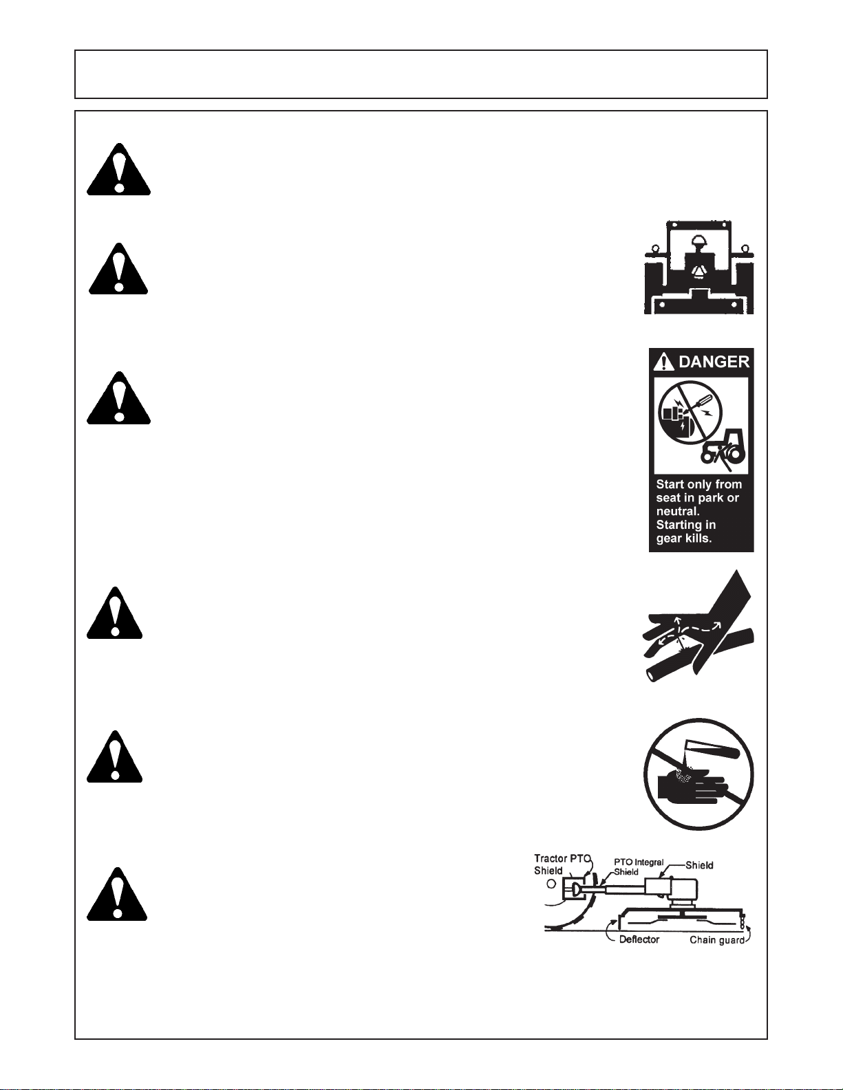
Perform service, repairs and lubrication according to the maintenance section. Ensure the unit
is properly lubricated as specified in the lubrication schedule and all bolts and nuts are properly
torqued. Failure to properly service, repair and maintain this Implement in good operating
condition could cause component failure and possible serious injury or even death. (SG-35)
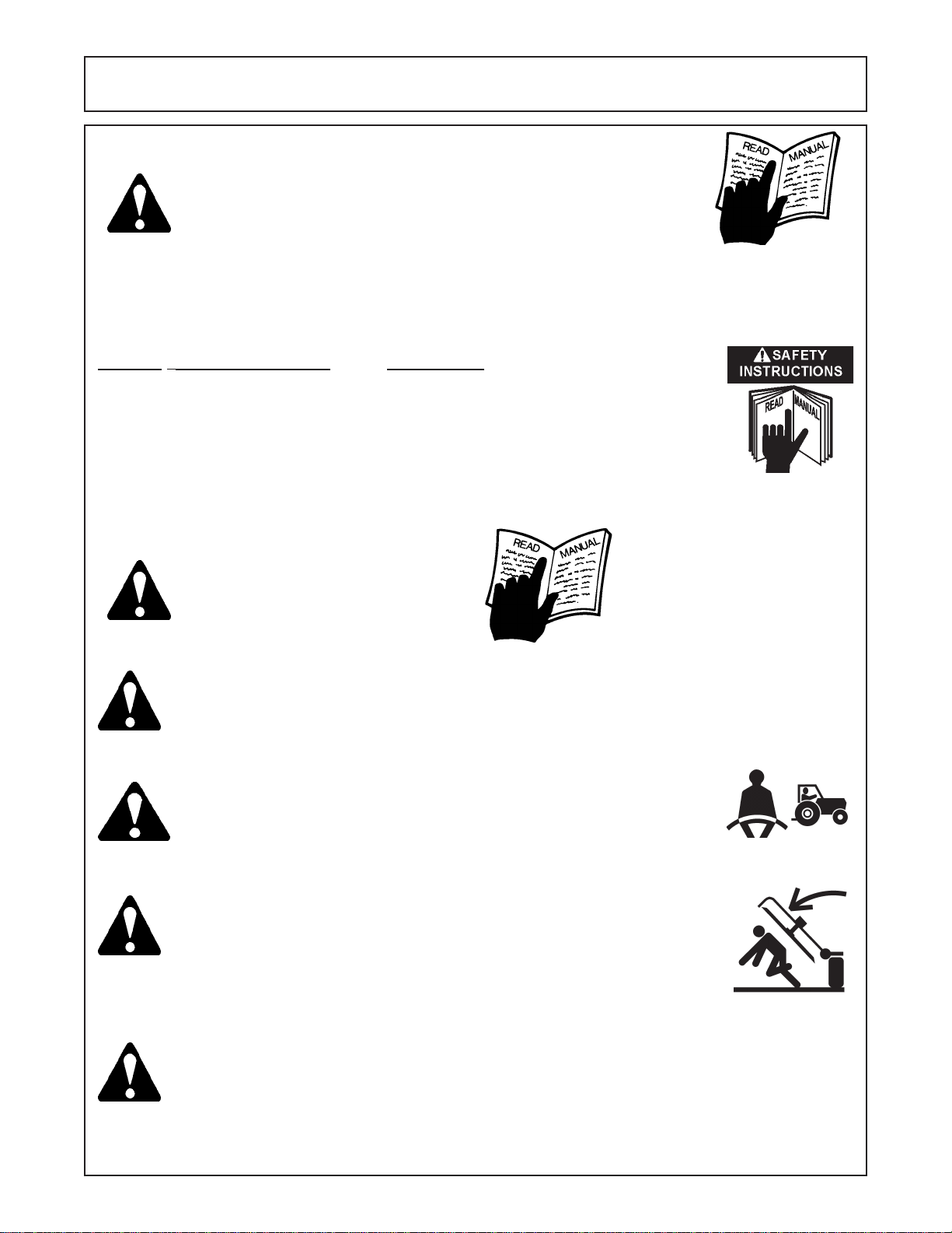
Operate this Equipment only with a Tractor equipped with an
approved roll-over-protective system (ROPS). Always wear seat
belts. Serious injury or even death could result from falling off the
tractor--particularly during a turnover when the operator could be
pinned under the ROPS. (SG-7)
Never work under the Implement, the framework, or any lifted component unless the Implement is securely supported or blocked up to
prevent sudden or inadvertent falling which could cause serious injury
or even death. (SG-14)
Use caution and wear protective gloves when handling sharp objects such as blades, knives,
and other cutting edges. Be alert to worn component surfaces which have sharp edges. Sharp
surfaces can inflict severe laceration injuries if proper hand protection is not worn. (SG-37)
A-Boom (JD 6615 / 7615 Asy Instruction Manual) 07/03
© 2003Alamo Group Inc.
Safety Section - 3
Page 10
SAFETY
WARNING!
WARNING!
WARNING!
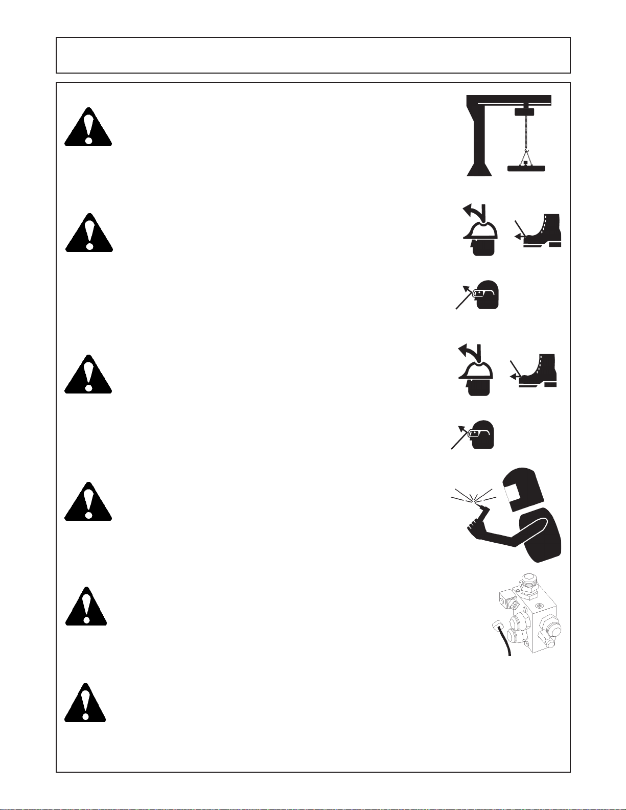
Many of the parts are heavy and require lifting assistance. Do not try to
lift the heavy parts by yourself. Get help from another employee or from
an overhead crane.
The operator and all support personnel should wear hard hats,
safety shoes, safety glasses, and proper hearing protection at all
times for protection from injury including injury from items thrown by
the equipment. (SG-16)
Always wear safety shoes with steel toes when working on this equipment.
It is recommended that the safety shoes have metatarsal guards.
WARNING!
DANGER! Always disconnect the wire leads from the mower valve solenoid before
DANGER!
When welding use Welding hood with the appropriate OSHA required
protective lens, welding apron, and welding gloves.
performing service on the Tractor or Mower. Use caution when working
on the Tractor or Mower. Tractor engine must be stopped before
working on Mower or Tractor. The Mower Blades could inadvertently be
turned on without warning and cause immediate dismemberment, injury
or death. (SBM-12)
Never run the tractor engine in a closed building or without adequate
ventilation. The exhaust fumes can be hazardous to your health.
(SG-23)
A-Boom (JD 6615 / 7615 Asy Instruction Manual) 07/03
© 2003 Alamo Group Inc.
Safety Section - 4
Page 11
SAFETY
DANGER!
WARNING!
DANGER!
Before starting the mower make sure the area is clear and the floor has
been swept. The mower blade can throw objects several hundred feet.
Thrown objects could damge property or cause severe bodily injuries even
death.
Make certain that the “Slow Moving Vehicle” (SMV) sign is installed in
such a way as to be clearly visible and legible. When transporting the
Equipment use the Tractor flashing warning lights and follow all local traffic
regulations. (SG-6)
Start tractor only when properly seated in the Tractor seat. Starting a
tractor in gear can result in injury or death. Read the Tractor operators
manual for proper starting instructions. (SG-13)
DANGER!
WARNING!
DANGER! All Safety Shields, Guards and Safety devices including
Do not operate this Equipment with hydraulic oil leaking. Oil is
expensive and its presence could present a hazard. Do not check for
leaks with your hand! Use a piece of heavy paper or cardboard. Highpressure oil streams from breaks in the line could penetrate the skin
and cause tissue damage including gangrene. If oil does penetrate the
skin, have the injury treated immediately by a physician knowledgeable and skilled in this procedure. (SG-15)
Always read carefully and comply fully with the manufacturers instructions when handling oil, solvents, cleansers, and any other chemical
agent. (SG-22)
(but not limited to) - the Deflectors, Chain Guards, Steel
Guards, Gearbox Shields, PTO integral shields , and
Retractable Door Shields should be used and maintained in good working condition. All safety devices
should be inspected carefully at least daily for missing
or broken components. Missing, broken, or worn items
must be replaced at once to reduce the possibility of
injury or death from thrown objects, entanglement, or
blade contact. (SGM-3)
A-Boom (JD 6615 / 7615 Asy Instruction Manual) 07/03
© 2003Alamo Group Inc.
Safety Section - 5
Page 12
SAFETY
DANGER!
DANGER! Operate the Tractor and/or Implement controls only while properly seated
WARNING!
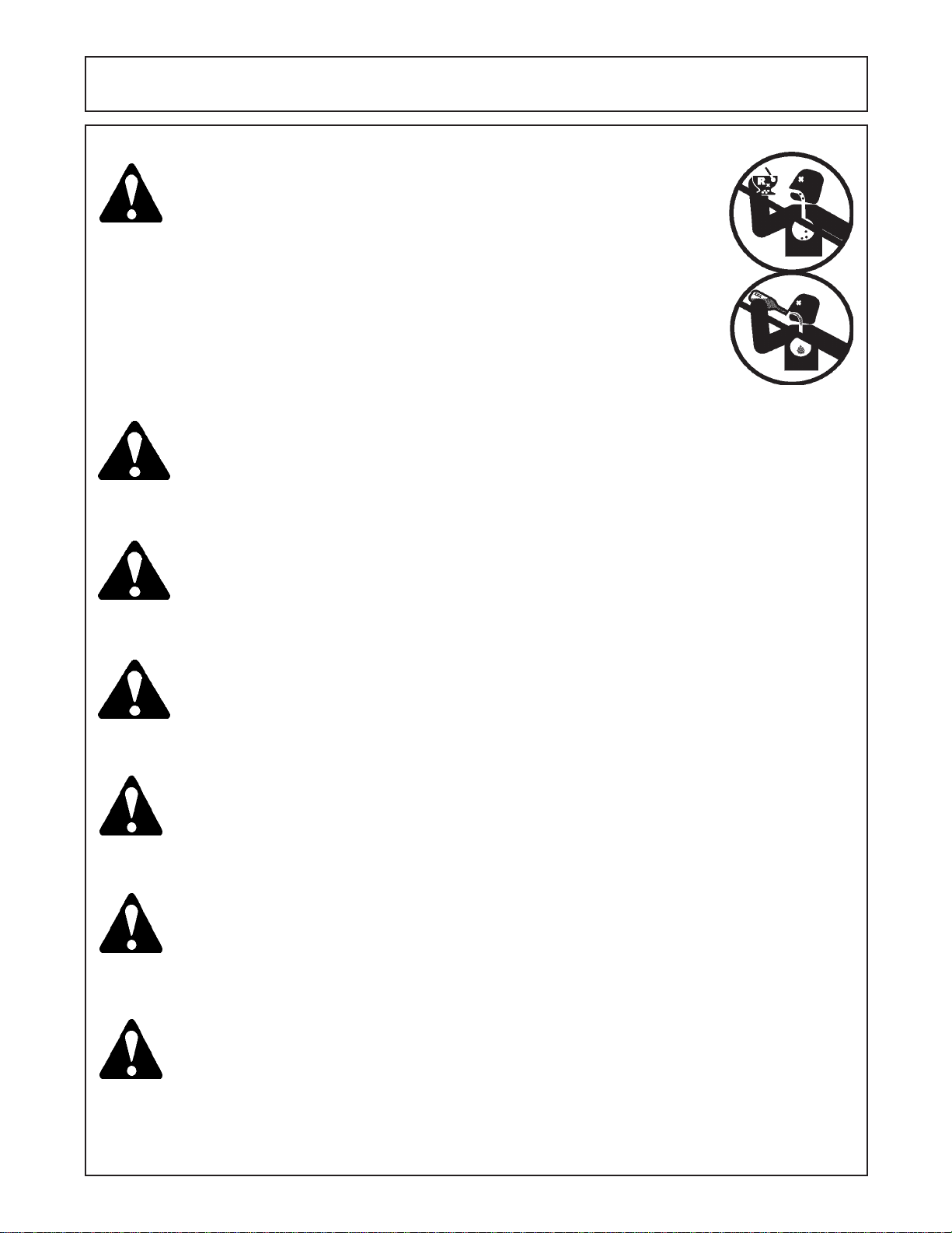
NEVER use drugs or alcohol immediately before or while operating the
Tractor and Implement. Drugs and alcohol will affect an operator’s
alertness and coordination and therefore affect the operator’s ability to
operate the equipment safely. Before operating the Tractor or Implement, an operator on prescription or over-the-counter medication must
consult a medical professional regarding any side effects of the medication that would hinder their ability to operate the Equipment safely.
NEVER knowingly allow anyone to operate this equipment when their
alertness or coordination is impaired. Serious injury or death to the
operator or others could result if the operator is under the influence of
drugs or alcohol. (SG-27)
in the Tractor seat with the seat belt securely fastened around you.
Inadvertent movement of the Tractor or Implement may cause serious
injury or death. (SG-29)
Engine Exhaust, some of its constituents, and certain vehicle
components contain or emit chemicals known to the state of
California to cause cancer and birth defects or other
reproductive harm. (SG-30)
WARNING!
WARNING!
WARNING!
WARNING!
Battery posts, terminals and related accessories contain lead
and lead compounds, chemicals known to the state of California to cause cancer and birth defects or other reproductive
harm. W ash Hands after handling. (SG-31)
Use extreme caution when getting onto the Implement to perform repairs, maintenance and
when removing accumulated material. Only stand on solid flat surfaces to ensure good footing.
Use a ladder or raised stand to access high spots which cannot be reached from gound level.
Slipping and falling can cause serious injury or death. (SG-33)
Avoid contact with hot surfaces including hydraulic oil tanks, pumps, motors, valves and hose
connections. Relieve hydraulic pressure before performing maintenance or repairs. Use
gloves and eye protection when servicing hot components. Contact with a hot surface or fluid
can cause serious injury from burns or scalding. (SG-34)
Avoid contact with hot surfaces of the engine or muffler. Use gloves and eye protection when
servicing hot components. Contact with a hot surface or fluid can cause serious injury from
burns or scalding. (SG-38)
A-Boom (JD 6615 / 7615 Asy Instruction Manual) 07/03
© 2003 Alamo Group Inc.
Safety Section - 6
Page 13

Section 1
A-BOOM
TOOL REQUIREMENTS
AND
PRE-DELIVER Y INSPECTION
CHECKLIST
A-Boom (JD 6615 / 7615 Asy Instruction Manual) 07/03
© 2003 Alamo Group Inc.
Section1 - 1
Page 14

Assembly
Tools, Supplies and Equipment Needed
Tools that are recommended to complete this assembly. There are number of different ways
to do things, some items are recommended to make assembly easier but may not be
required.
1. An over Head Hoist, the hoist (or Lift) should be a 2-1/2 ton capacity minimum. Hoist should
be able to move and stop within fractions of an inch. Hoist should also have a 12 foot lift
(Required).
2. Compressed Air, Air must be filtered and dry. A Safety air nozzle for blowing out Hoses and
Fitting prior to assembly. (Required).
3. Complete Air Impact Sockets, 1/2" Drive and 3/4” drive (Recommended).
4. Torque Wrench, 400-ft lb. rating, can use a Torque Amplifier Wrench. (Required)
5. Complete Set of Hand Wrenches from 7/16" to 2" (Recommended).
6. Assortment of Screwdrivers, (Short ones and Long ones). (Required)
7. Electric Grinder or Air Grinder, Size according to needs (Required).
8. Burr Grinder, Electric or Air optional, for resizing Holes and removing Burrs from stamped
metal or stamped holes. (Required)
9. Welder, capable of welding up to 3/8" material, Use experienced Welder Personel. (Required)
10. Flame Proof or flame retardant Material to Cover and protect Tractor finish and components
during assembly. (Required)
11. A good fire Extinguisher on hand before any welding or grinding begins. (Required)
12. Clean dust free work area, clean Lint Free towels or wipes. Do not do any welding, use
compressed Air or lay out any component unless area is clean. Material the size of a human
hair can contaminate the Hydraulic System (Required).
13. A place to keep all Components separate and clean untill ready for them (Recommended)
14. Electrical Butt connectors and Electrical Pliers. (Required)
15. Paint Scraper to remove Paint before welding. (Recommended)
16. Floor Jack, 2-1/2 Ton capacity (Required)
17. An asortment of large C-Clamps (Required)
A-Boom (JD 6615/ 7615 Asy Instruction Manual) 07/03
© 2003 Alamo Group Inc.
Section 1 - 2
Page 15

A-BOOM PRE-DELIVERY INSPECTION CHECKLIST
Pre-Operation Inspection: After Assembly is complete. Check the following items
before operating the unit to assure that they are properly assembled. (See following page 1-4
for component location)
Saftey Equipment:
----- Operators Manual is with Unit.
----- The Safety Decals are installed as listed in the Assembly Manual.
----- Valve operation plate is installed.
----- Operators cage or Tractor Cab is in place. (Item 1 page 1-5)
----- Deflectors are installed on the Mower Head. (Item 2 page 1-5)
----- Tractor Rops or Cab with seatbels installed properly.
Frame and Boom:
----- Axle Plate Bolts are torqued to 240 ft. lbs. (Item 3 page 1-5)
----- Boom Rest Axle Plate Bolts are torqued to 240 ft. lbs.
----- Front Rail Bolts are torqued to 170 ft. lbs. (Item 17 page 1-5)
----- Front Support Bolts are torqued to 240 ft. lbs. (Item 4 page 1-5)
----- Hydraulic Tank mounting Pins / Bolts in place correctly.
----- Boom Main Pins are torqued to 170 ft. lbs.
----- King Pin Retaining Nut is properly locked in place.
----- All Welds inspected toinsure proper welds and locations.
Hydraulic System:
----- Oil Level in Hydraulic Tank is within the sight gauge. (Item 5 page 1-5)
----- Hose connections are tightented according to specifications.
----- Hoses do not have any kinks or twist in them.
----- Front Pump Shaft adapter bolts are tight. (Item 6 page 1-5)
----- Front Pump Shaft Coupler / Drive Shaft is lubricated and has an anti-seize compound
on the Splines of Pump and Shafts. (Item 7 page 1-5)
----- The Pump Drive Shaft has correct alignment.
----- Suction Hose has no leaks or kinks.
Rotary Mower Head:
----- Skid Shoe Bolts are torqued to 120 ft. lbs. (Item 8 page 1-5)
----- Spindle Housing Bolts are torqued to 400 ft. lbs. (Item 9 page 1-5)
----- The Spindle Housing is properly lubricated. (item 10 page 1-5)
----- Motor Bolts are torqued to 120 ft. lbs. (Item 11 page 1-5)
----- Blade Carrier (Bar) Bolts torque to 400 ft. lbs. (Item 12 page 1-5)
----- All Blade Bolts are torqued, the retainings Pins are in place. (item 13 page 1-5)
----- Blades Swing freely. (Item 14 page 1-5)
A-Boom (JD 6615 / 7615 Asy Instruction Manual) 07/03
© 2003 Alamo Group Inc.
Section1 - 3
Page 16

A-BOOM PRE-DELIVERY INSPECTION CHECKLIST
Pre-Operation Inspection: Check the following items before operating the unit to assure
that they are properly assembled. (See following page 1-4 for component location)
Flail Mower Head:
___ Skid Shoe Bolts are torqued to 120 ft-lbs (Item 15 page 5)
___ Motor Bolts are torqued to 120 ft-lbs
___ Belt Alignment& tension adjustment is correct
___ Cutter shaft bearings are properly lubricated
___ Roller bearings are properly lubricated (Item 16 Page 5)
___ Blades swing freely
Tractor Mower Operation Inspection:
___ Using all Safety precautions, operate the Tractor and Mower unit for 30 minutes and
while the unit is running check the following items: Note! Only make adjustments after
the mower has been turned off and all motion has stopped and all hydraulic pressure
has been relieved.
___ No Hydraulic oil leaks at the hose connections
___ Operate the boom and mower head throughout its full range of motion and check
for hose's rubbing, pinching, or kinking.
___ Make sure the Return Filter Gauge is reading in the Green after Oil is warm.
___ Check the function of the Mower Head On-Off Valve and switch for proper function
___ Make sure that the tractor will not start with the mower on-off switch in the on
position.
___ Check the Blade Rotation for the Rotary Mower Head to make sure it is turning
Clockwise looking from the top of the mower deck.
___ Make sure the control valve boom movements agree with the valve operation decal.
___ Make Sure Boom Movement operates as expected and is smooth and under control
(no air in the control system)
___ Look for any unusual or excessive noise or vibrations.
___ Make sure all Wheel Weights are installed, Tires are Filled with liquid and Counter
Weight is installed
___ Make sure the left rear wheel of the tractor stays on the ground when the boom is
fully extended horizontally with 200 lbs. placed on the outside of the mower head.
Post-Operation Inspection:
___ Check that the oil in the hydraulic tank has not turned milky in color or has foam on top.
___ Check that there are no loose fasteners or hardware.
A-Boom (JD 6615/ 7615 Asy Instruction Manual) 07/03
© 2003 Alamo Group Inc.
Section 1 - 4
Page 17
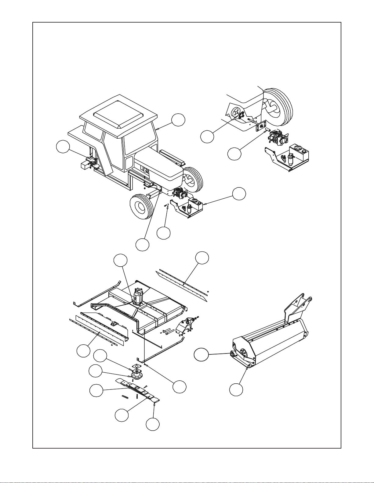
Tractor - Mower Component Location
For Check List
1
6
3
7
5
17
4
11
2
10
9
12
8
2
16
15
13
14
A-Boom (JD 6615 / 7615 Asy Instruction Manual) 07/03
© 2003 Alamo Group Inc.
Section1 - 5
Page 18

Section 2
A-BOOM
Wheel Weight
Inst allation
A-Boom (JD 6615 / 7615 Asy Instruction Manual) 07/03
© 2003 Alamo Group Inc.
Section 2 - 1
Page 19
Rear Wheel Counter Weight
Fill Left Rear Wheel with Liquid:
The Left Rear Wheel must be filled with liguid. Alamo Industrial recommends a Calcium Cloride
Water Mixture. The recommended Ratio of a 30 / 70 mix (30% Calcium Cloride and 70% Water), this
mixture will add weight at about 10.5 lbs per gallon. Follow the Mixture procedures furnished by the
Manufactured of the Brand of Calcium Cloride that you are useing. It is also recommended that a trained
person installs the calcium Cloride. Calcium Cloride must be added in addition to the Steel Wheel
Wieght and the Counter Weight that hangs on the Left Side. It is Not recommended to use straight
Water in the Wheel as this would not provide protection against freezing. A 30/70 Calcium Cloride
Water mixture provides anti-freeze to approx -50 deg. F. below 0.
Rotate Washer to Match Bolt
Circle dia. and Washer fits into
Wheel Weight Slot.
3
4
2
1
Bolt is shown extra long in
drawing for illustration only
Figure 1
Item Part No. Qty Description
1 02979603 3 Hex Head Bolt, 7/8" NC X 16"
2 02971569 3 Wheel Weight Washer, Special
3 02970758 1 Wheel Weight Casting, 1400 lbs.
4 5JRC1490 3 Locknut, Top Lock 7/8" NC
Note: some Older Units used a All Thread Rod with Hex Nuts Lock Nuts, with Flat Washer
and Lock washer. This was replaced with the Bolt Type shown above. These Bolt and Nut
combinations will replace the old All Thread type.
A-Boom (JD 6615 / 7615 Asy Instruction Manual) 07/03
© 2003 Alamo Group Inc.
Section 2 - 2
Page 20
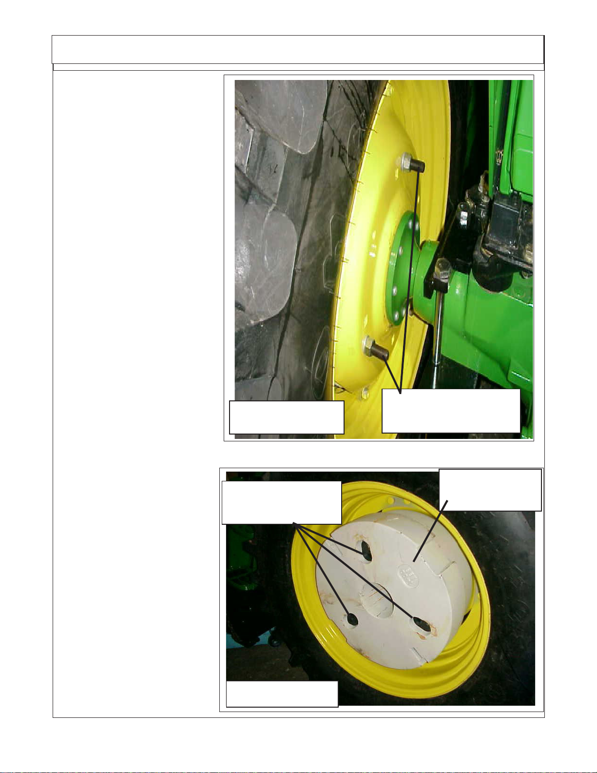
Rear Wheel Counter Weight
Installing Wheel Weight
1. This Wheel Weight is 1400
lbs. Always use caution when
working with it.
2. Locate the three Holes in
LH Rear Wheel. Make sure these
holes are 15/16" dia. if not, they
must be reamed out.
3. Lift Left Rear Tractor
Wheel till it just clears the ground.
This will allow the Wheel to be
rotated when aligning mounting
holes for Weight.
4. Using a forklift, lift Wheel
Weight into Wheel. When Wheel
Weight is centered in Wheel Secure Forklift and Set Parking Brake
on Forklift. Insert one of the three
bolts through Weight and Wheel
(Rotate Wheel to align holes if
needed). Install a Hex Lock Nut on
inside. Insert the other two Bolts
through Weight and Wheel and
start the other two Locknuts. Do
not tighten yet. (See Figure 2)
Figure 2
Wheel Weight Mntg
Lock Nut
5. Looking at the outside
make sure the three special Washers (Figure 1 Item 2) are aligned
with the Slots in the Wheel Weight.
Tighten the three Bolts now. You
will need an assistant to hold the
other Side while you are tightening
the Bolts. While tightening Bolts,
check to make sure the three special washers are seated correctly.
If these Bolts are tightened and
washer are not seated into the
recess on Wheel Weight, damage will occur. (See Figure 3)
Wheel Weight
Special Washers
Mounting Bolts
Part # 02971569
(3)
6. Remove forklift away from
Wheel and Weight. Re-check
tightness of Wheel Weight retaining Bolts. Bolts should torque to
500 ft. lbs.
A-Boom (JD 6615 / 7615 Asy Instruction Manual) 07/03
Figure 3
Wheel Weight
1400 lbs.
© 2003 Alamo Group Inc.
Section 2 - 3
Page 21

NOTES
A-Boom (JD 6615 / 7615 Asy Instruction Manual) 07/03
© 2003 Alamo Group Inc.
Section 2 - 4
Page 22

Section 3
A-Boom
Front Pump &
Drive Shaft
Inst allation
A-Boom (JD 6615 / 7615 Asy Instruction Manual) 07/03
© 2003 Alamo Group Inc.
Section 3 - 1
Page 23
Pump / Drive Assembly Instructions
Installing Pump, Pump Drive Components and Hydraulic Tank:
This Section covers the installation of Pump Drive Components, Pump Assembly and the
Hydraulic Tank. Some precautions must be followed during the Assembly Process and before unit is
ever started for the first time.
1. Tractor must be disabled to prevent accidental engine start and prevent daamge to components.
2. All Fittings, Hose, Cylinders, Tank must be kept plugged at all times, No part of the Hydraulic
System can be left open at any time
3. All Tools, Work Area, Components and Workers Hands must remain Clean when working on
any part of the Hydraulic System.
4. All components should be rechecked for tightness at least twice, Hose routing also double
checked.
Existing JD Bolts & Washers
2
JD Tractor Crankshaft Pulley
7
6
3
10
JD Tractor Frame Rails
Pump
4
8,9
Item Part No. Qty Description
1 02976087 ar Front Pump Plate (Standard) Shown
02979080 ar Front Pump Plate (Optional w/ Pump Guard)
2 02979790 1 Pulley Adapter
3 02973712A 1 Driveline Assembly
4 02975669 4 Bolt, 20 mm 2.5P X 60 mm GR 10.9
5 02971158 4 Lockwasher, 20 mm
6 02976344 4 Bolt, 7/16" NC X 1-1/4" GR 8
7 00022200 4 Lockwasher, 7/16"
8 02892000 2 Bolt, 1/2" NC X 1-1/2" GR8
9 00001300 2 Lockwasher, 1/2"
10 02978480 2 Spacer, Pump Plate (JD 6615 Series)
5
JD Tractor Front Casting
1
Figure 1
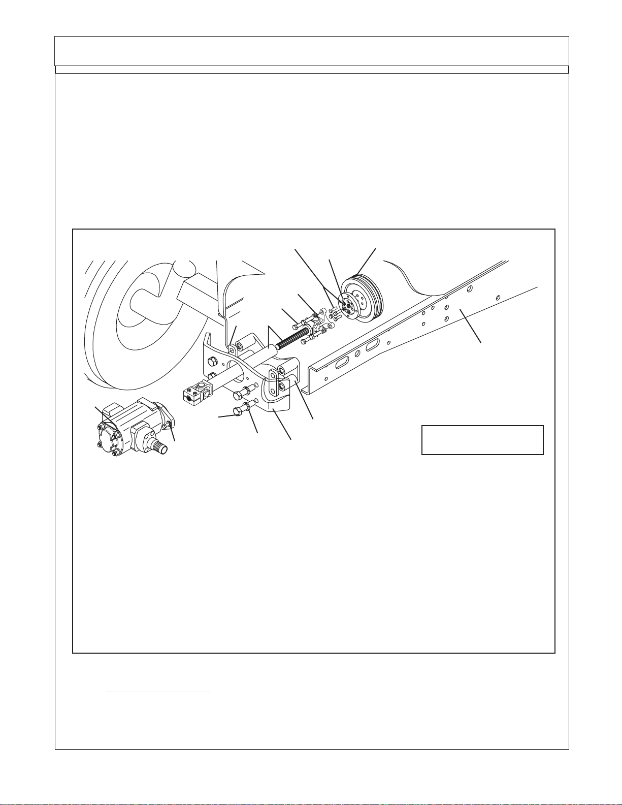
Installing Pump Drive Components:
1. Remove Front Cover (See Figure 2), Remove the 4 plastic plugs shown in figure 1 and discard
them, they will not be needed. Remove the 2 Allen Head Cover Retaining Bolts. After removal, this front
cover will not be used. The front Casting will have a Driveline Hole in it. (See Figure 3). This will be the
same on 2 WD or 4 WD.
A-Boom (JD 6615 / 7615 Asy Instruction Manual) 07/03
© 2003 Alamo Group Inc.
Section 3 - 2
Page 24
Pump / Drive Assembly Instructions
Installing Pump Drive
Components:
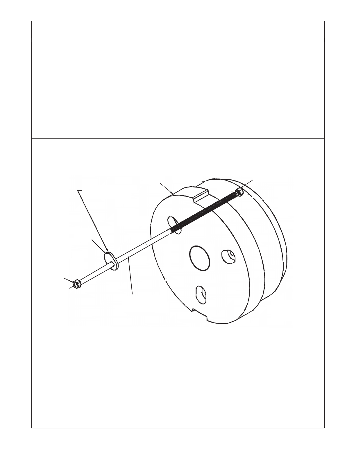
2. Access to Crankshaft Pulley. The Factory
Crankshaft Pulley will not need to be removed. The
Pulley Adapter will be bolted to the Factory Crankshaft Pulley.
3. Install Pulley Adapter. The Pulley adapter
to be used is a round plate with 4 threaded
holes and four non-threaded holes in it. Notice
this pulley adapter will not have a center hole in
it (See Figure 4). The Non-treaded holes are
used to mount the Adapter to the Pulley using
bolts # 02979791 (10mm 1.5 P X 35mm
Gr.10.9) & Lockwasher # 00755954 (10 mm).
Do not use longer bolts to mount Pulley Adapter
to Pulley than is supplied with mounting kit.
4. Driveshaft Assembly. The drive shaft is a
two piece Assembly, an inner and outer shaft
assembly (See Figure 5). The Shaft End has a
four bolt flange yokes on it that connect to the
Crankshaft Pulley Adapter. The Tube end has a
splined clamp yoke on it that connects to the
Pump. This Drive Shaft connects to the Pulley
Adapter. Note that the Universals of the Driveshaft
are in time. When installed in tractor they should be
in time as shown, both Yokes the same.
Plastic Plugs
Figure 2
Front Cover Removed
Pump Plate Mounting Holes
Figure 3
Front Cover
Cover
Retaining
Bolts (2)
4
Non-Threaded
Holes
Figure 4
A-Boom (JD 6615 / 7615 Asy Instruction Manual) 07/03
© 2003 Alamo Group Inc.
4 Threaded
Holes
Pulley Adapter
Part # 02979790
Figure 5
Section 3 - 3
Splined Clamp Yoke
/ Tube End
Flange Yoke
/ Shaft End
Drive Shaft
Assembly
Page 25
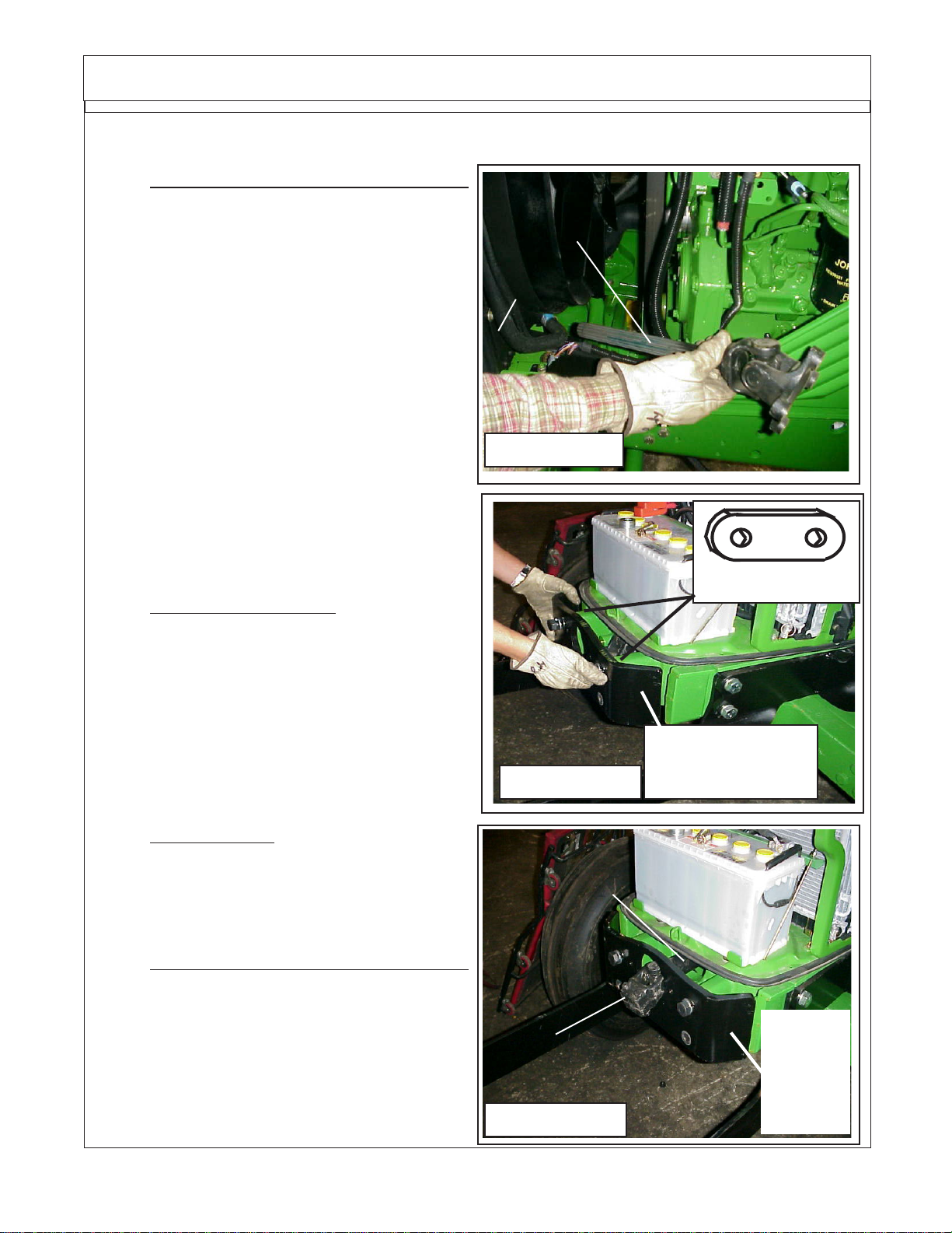
Pump / Drive Assembly Instructions
Installing Pump Drive Components: (continued)
6. Install Shaft End of Driveline / Engine end.
Install the Shaft 1/2 Assembly w/ Flanged Yoke into
the Engine compartment of Tractor, install it from
the LH front Side down and under radiator. (See
Figure 6). This needs to be installed this way
because the Flange Yoke will not go through the
Crankshaft access hole in the front of the Tractor
(See Figure 3). Bolt the Flange Yoke to the Pulley
Adapter using the four 7/16" X 1-1/4" Bolts (Part #
02976344), use the four Lock Washers (Part #
00022200), put Locktite on the threads of the Bolts
and install them into Pulley Adapter. To Tighten
these four Bolts, use a long extension and go
through the front Crankshaft Pulley access hole in
front of Tractor. Do Not use bolts longer than 1-1/4"
long, longer bolts will damage
Crankshaft Pulley.
Shaft 1/2 Assembly
w/ Flanged Yoke
Tractor
Radiator
Figure 6
Tractor Engine
Left Hand front side
of Tractor
Installing Pump Mount Plate & Tube
End of Driveshaft:
1. Install Pump Mount Plate. Install Front Pump
Plate # 02976087 standard mount plate (See
Figure 7) or # 02979080 optional Pump Mount
Plate w/ Pump Guard built on. (Not Shown) use
the 2 Spacers on the JD 6615 Series, Do not install
Pump Mount Plate without using these Spacers.
The Spacers are for Tractor Hood Clearance. Insert
the 4 bolts and lock washers into Pump Mount Plate
and spacers (See Figure 7), tighten them to re-
quired Torque (See Bolt Torque Chart).
2. Driveline timeing means the universal joints
are both the same position when driveline half is slid
together. If they are not timed, it will decrease the life
of the universal joint and in some cases could cause
a vibration. (See Figure 5 on previous page)
3. Install Tube End of Driveline / Pump End.
Slide the Tube half of driveshaft through Pump
Mount Plate and Tractor Crankshaft Access Hole
(See Figure 8). You will have to align the Universals
when doing this (time the Driveshaft). Slide the two
together where the Universal are in time (See
Figure 5 on previous page), this will help the
driveshaft to operate smoothly.
Figure 7
Tube End of
Driveshaft
Splined
Clamp Yoke
Figure 8
Spacer (2)
Standard Pump
Mount Plate
Shown
Standard
Pump
Mount
Plate
Shown
A-Boom (JD 6615 / 7615 Asy Instruction Manual) 07/03
© 2003 Alamo Group Inc.
Section 3 - 4
Page 26
Pump / Drive Assembly Instructions
Installing Pump Mount Plate & Tube End of Driveshaft: (continued)
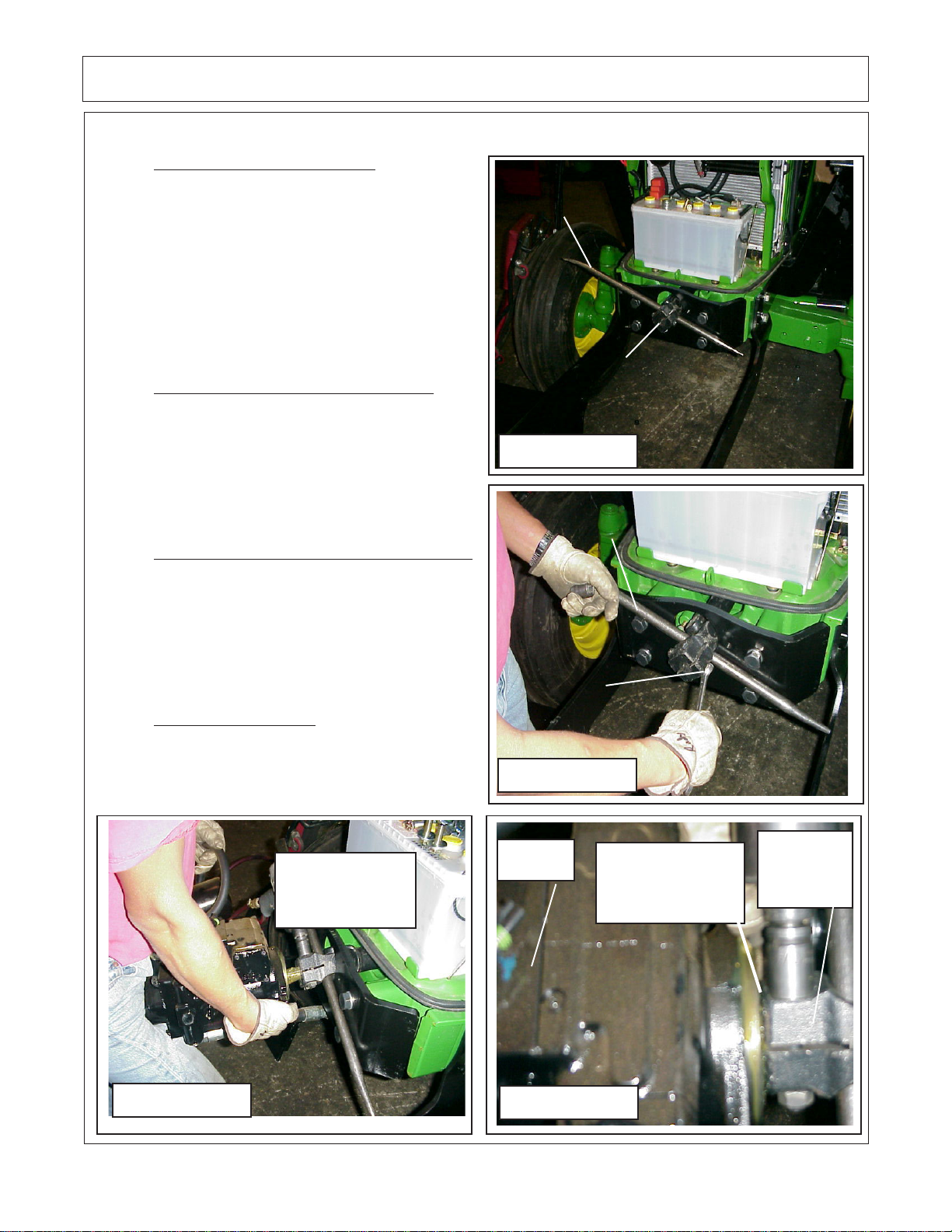
4. Loosen Splined Clamp Yoke. Insert a bar
through the Yoke to hold Driveshaft up and to help
loosen the Bolts in the clamp Yoke (See Figure 10).
This can be loosened with a hand Wrench or a
Socket whichever is easier for you (See Figure 10).
Some times it is easier to test fit the Tube End of
Driveshaft to the Pump while the Pump is on the
bench.
Bar to Hold
Drive Shaft
Installing Pump:
1. Install Pump into Splined Clamp Yoke. Slide
the Pump Splined Shaft into the Spline Clamp Yoke
(See Figure 11). Leave the Bar stuck in through the
Yoke as shown, this helps to stabilize the Yoke as
you slide Shaft into the Yoke. Once Pump is slid into
the Splined Yoke, keep the Pump supported; DO
NOT let the Pump hang on the Yoke unsupported.
2. Pump / Driveshaft Yoke Gap Adjustment.
After sliding Pump Shaft into Splined Clamp Yoke,
the Pump and Yoke must be slid apart far enough to
allow for a 1/16" to 1/8" Gap between them. The Yoke
edge cannot touch the Pump Housing; it will damage
the Housing and the Yoke if it does. This is a very
critical adjustment (See Figure 12).
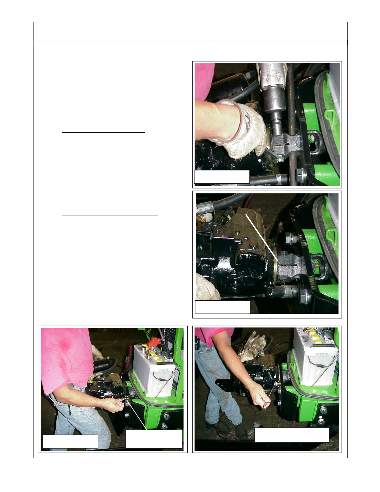
3. Tighten Clamp Yoke. After Gap between
Yoke and Pump has been adjusted tighten the Bolts
& Nuts on the Clamp Yoke (See Figure 12 & 13).
Check Pump to Yoke Gap once more. Keep Pump
Supported do not let it hang on Yoke.
Driveshaft, Spline
Clamp Yoke End
Figure 9
Bar to Hold
Driveshaft
Loosen
Clamp
Yoke Bolt
Figure 10
Align Splines of
Pump Shaft w/
Splines of Yoke
Bar to Hold
Figure 11
A-Boom (JD 6615 / 7615 Asy Instruction Manual) 07/03
© 2003 Alamo Group Inc.
Driveshaft
Section 3 - 5
Pump
Assembly
1/16" to 1/8" Gap
between Pump &
Figure 12
Yoke (must)
Splined
Clamp
Yoke
Page 27
Pump / Drive Assembly Instructions
Installing Pump: (continued)
5. Mount Pump to Pump Plate. Remove the
Bar that is slid through the Driveshaft Yoke and
push the Pump inward (See Figure 14). This will
make the two piece Driveshaft slide together allowing the Pump to be pushed towards the tractor.
Do this untill the Pump is against the Pump Plate
(See Figure 15).
6. Install Pump Mounting Bolts. While holding
in on the Pump (See Figure 15) start the two
Pump Retaining Bolts. Make sure both Bolts are
started well before you stop supporting pump. The
Bolts should be snugged untill pump sits level
before you stop supporting it (See Figure 16). Let
go of the Pump, it may slide back some and leave
a slight gap between Pump and Mounting Plate
(See Figure 16).
7. Tightening Pump Mounting Bolts. There is
a shoulder on Pump Flange that must line up
through hole in Pump Mounting Plate (See Figure
14), if the Pump is slid back as in figure 14 try to
push it inward untill it is against Pump Mount Plate
as shown (See Figure 15). Slowly and alternating
from Left to the Right side, tighten the Pump
mounting bolts untill they are tight. DO NOT FORCE
Pump through Pump Mount Plate, if it will not freely
slide in check for a problem of some kind. Excess
force could damage Pump Housing. (See Figure
16). Do Not remove any Plastic caps from Pump
inlet or outlet at this time, keep all openings plugged
and sealed to keep them clean.
Figure 13
Gap ? Check, this must have a gap
between Pump & drivesahft
Figure 14
Pump Retaining
Figure 15
A-Boom (JD 6615 / 7615 Asy Instruction Manual) 07/03
© 2003 Alamo Group Inc.
Bolts (2)
Section 3 - 6
Figure 16
Page 28
Pump / Drive Assembly Instructions
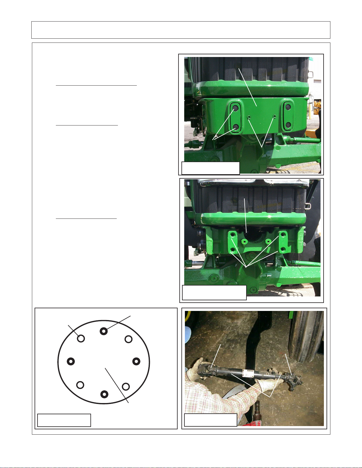
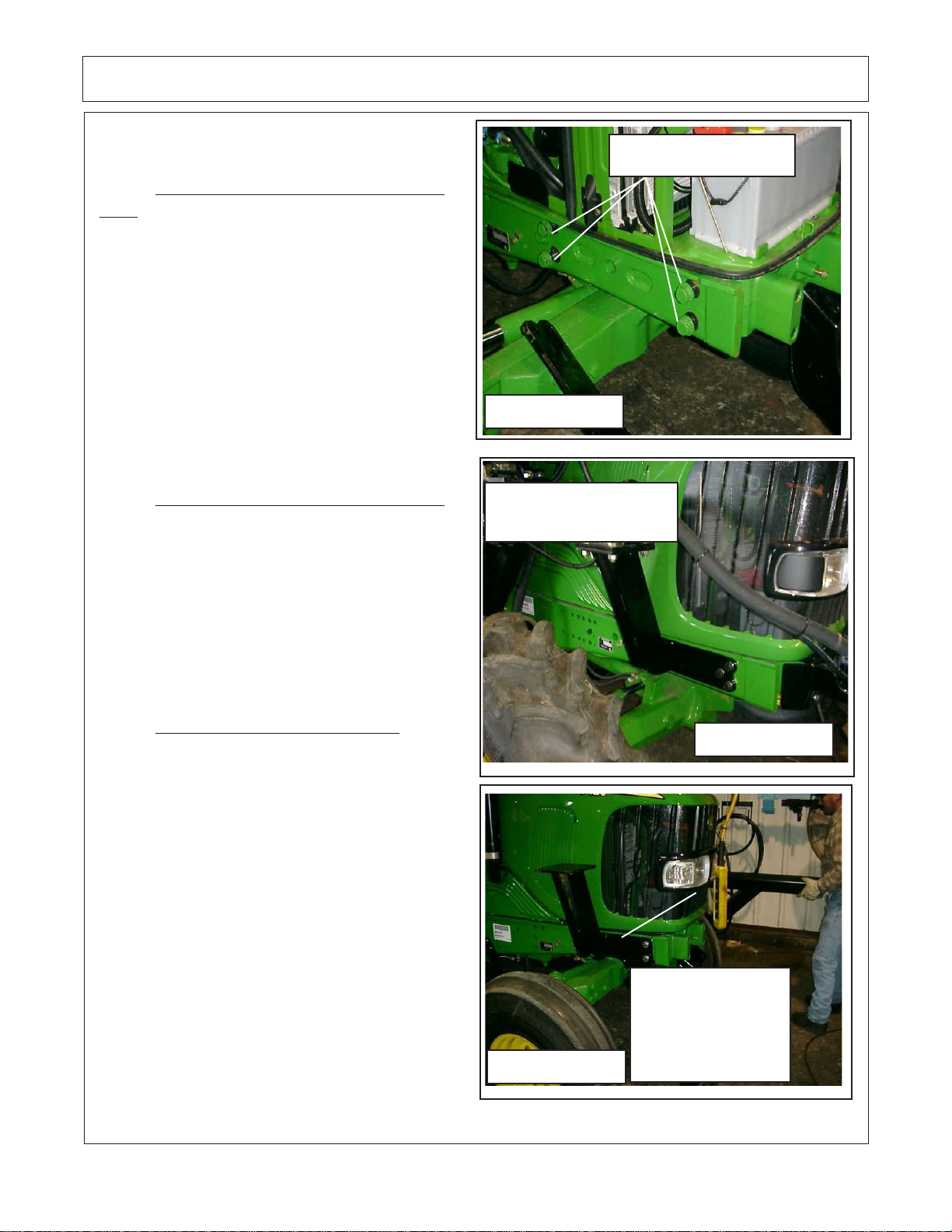
Install Front frame Rail Support s:
1. Remove Bolts from Tractor Frame
Rails. Find the front most 4 Bolts in the Tractor
Frame Rail, There are 4 on the RH side and 4 on
the LH Side. DO NOT REMOVE THE BOLTS
FROM BOTH SIDES AT THE SAME TIME,
ONLY do one side at a time the RH or the LH.
For illustration start with the RH Side (See
Figure 17). The RH & LH Frame Rail Supports
have a Right and a Left. They will not interchange and must be mounted on the correct
side. Notice the way they are built, the Plate part
that bolts to Tractor is longer in the front on both
LH & RH. Make sure the longest part is to the
front (See Figure 18).
2. Install Frame Rail Support RH Side.
This works best with a 2 man team. The RH
Frame Rail Support the is held on with the 5
bolts that Bolts that are supplied w/ mounting
kit. Start all 5 bolts with Lockwasher before any
of the 4 are tightened (See Figure 18). When
tightened down it will look like the picture in
Figure 18. Tighten the four retaining bolts for the
RH Frame Rail Support before lossening or
removeing the bolts on the LH side.
Tractor Frame Rail
Bolts(5)
Figure 17
Right Hand Frame rail
Support Shown
3. Install Frame Rail Support LH Side. Make
sure that the bolts on the RH side have been
tightened before removing the four bolts on the
LH side. The LH Frame Rail Support will install
the same as the RH side did. Remove the 4
bolts; Install the Front Frame Rail Support.
Tighten the 4 bolts through Tractor Frame Rail.
(See Figure 19).
Figure 19
A-Boom (JD 6615 / 7615 Asy Instruction Manual) 07/03
Figure 18
Mounting Plates on
Front Frame Rail
Support, the longer
part toward front on
RH and LH side
RH Frame
Rail Support
RH Tank
Mount Bracket
© 2003 Alamo Group Inc.
Section 3 - 7
Page 29

NOTES
A-Boom (JD 6615 / 7615 Asy Instruction Manual) 07/03
© 2003 Alamo Group Inc.
Section 3 - 8
Page 30

Section 4
A-Boom
Frame Rail / High Frame
Setup / Pre- Assembly
Inst allation
A-Boom(JD 6615/ 7615 Asy Instruction Manual) 07/03
© 2003 Alamo Group Inc.
Section 4 - 1
Page 31

Frame Rail Set Up
Frame Rail Pre-Assembly:
The Frame Rail Set UP. The Frame Rails for the Machete will be set up on the tractor,
positioned, measured but not welded. The Machete High frame is set on to Frame Rails,
positioned and leveled. After all is set up and positioned it will be Tack Welded in Place on Tractor.
Then it will be dis-assembled and welded up on the Shop floor. This is done to ensure better welds
and to enable the parts to be turned so the components can be Flat Welded. It has been found
that this will make the components stronger. This also gives a chance for all frame components
to be test fitted and broken loose during this trial if when another component makes the previous
one interferes.
The Tractor should be covered and protected from Spark from the Welder and Grinder
at all times. It will be your responsibility to protect the Tractor and its components. DO NOT WELD
or GRIND near any Glass or Painted Surface unless it is protected from sparks, these Sparks
will damage any surface.
The purpose for Setting Frame up, tack welding it then removing it, is because with the
amount of Welding that will have to be done these frame components will need to be repainted.
The repainting is easier with frames off. The Frame components are shipped already painted but
this is to protect the metal, plan on repainting them after welding.
DO NOT weld any frame or component untill instructed to do so in the instructions. Read
through this entire instruction book to be familiar with which part goes where and when.
DO NOT try to man handle large components alone, one slip can break a window,
damage a hood or worse. Note the order of assembly of other Assemblies, example the Pump
Drive Shaft, Front Rail Supports, Rear Stack Valve Modifications and Joystick Assembly are
assembled to Tractor before the frame rails. This is because some components will be in the way
of others after they are assembled..
A-Boom (JD 6615 / 7615 Asy Instruction Manual) 07/03
© 2003 Alamo Group Inc.
Section 4 - 2
Page 32

Frame Rail Installation
Frame Rail Pre-Assembly: (continued)
RH & LH Frame Rails. Shown below are example of Frame rails, There is a Right and Left Frame
Rail, They will not interchange from side to side. LH must be mounted on the Left and Right on the Right.
To ID which is which, the easiest way is to look for the Counter Weight Mounting Tubes (See Figure
1 Item 2), these are welded on to the LH Frame Rail Only. The Rail Mounting Pad (See Figure 1 Item
4) is loose and not welded to the front of the Frame Rail untill final assembly.
Figure 1
5
1
3
4
Item Part No. Qty Description
1 02979767 1 4 WD Frame Rail Weldment, LH (Shown)
02979768 1 4 WD Frame Rail Weldment, RH (Not Shown)
3 ------------- 2 Rear Mounting Plate (Welded on LH and RH Frame Rail)
4 02725900 2 Front Rail Mounting Pad (not welded to frame rail when recievedl)
5 02974704 2 Stabilizer Strap, (Axle Straps) Fit above Axle.
Note:
Item 3 is welded to both LH and RH Frame Rails from the factory. Item 4 will be welded on
during assembly procedures. Do not weld on any components until instructed to do so, then check
instructions carefully because some components are only to be tack welded then removed to be
welded later.
Actual Tube Design may vary from drawing above. Shown above is a general Frame
Rail Weldment. While Frame Rails may be designed different the mounting process will be the
same.
3 Point Arm Stabilizers on tractor will have to be removed when mounting Frame rails
and will have to be modified to be used again. This modification will be customers responsibility.
A-Boom(JD 6615/ 7615 Asy Instruction Manual) 07/03
© 2003 Alamo Group Inc.
Section 4 - 3
Page 33

Frame Rail Installation
Frame Rail Pre-Assembly: (continued)
Frame Rail Stiffener Kit (Crossmember). Shown below is the Frame Rail Stiffener Kit. This
mounts under the Tractor and will be added to the Frame Rails during Assembly. Item 5 Rail Support
Gussets are shipped loose and are not part of the Assembly, they will be bolted to the tractor and when
instructed you will need to weld the Frame Rail Support to them (See Figure 2).
Frame Stiiffener Kit
Frame Rail, RH Shown
Frame Rail Stiffener Kit
(Crossmember)
3,4
Item Part No. Qty Description
02970118 -- Frame Rail Stiffener Kit (Item 1 thru 4)
1 02970115 2 Rail Stiffener Weldment
2 02970086 1 Tube, Rail Stiffiner
3 02712500 4 Bolt, 1" NC X 4" GR8
4 5JRC1680 4 Locknut, 1" NC (Toplock)
5 02978499 2 Gusset Rail Support
Figure 2
5
1
2
A-Boom (JD 6615 / 7615 Asy Instruction Manual) 07/03
© 2003 Alamo Group Inc.
Section 4 - 4
Page 34

Frame Rail Installation
Frame Rail Pre-Assembly: (continued)
High Frame Mounting Tube Components. (See Figure 3 & 4) These Components are to be laid
out and will be tack welded to frame Rails and High frame during Pre-Assembly Process. Locate and
ID these Parts for later installation. Remember DO NOT Weld any components untill instructed to do
so.
High Frame Mounting Tube Componnets
1
Machete High
Frame
2
2A
RH Frame Rail
Front Shown
2
Figure 3
Item Part No. Qty Description
1 ---Ref----- 2 Mounting Tubes, (Length will Vary with Mount Kit).
02918600 4 Bolt, 3/4" X 2" Long (Not Shown)
00037200 4 Locknut, 3/4" Toplock (Not Shown
2 02966639 7 Bar Mounting Strap
2A 02966639 1 Bar Mounting Strap (Cut In Half)
3 00037200 8 Locknut, Toplock
4 02957039 8 Bolt, 3/4" X 10-1/2" Long
5 02966641 2 Angle Mount
2A
Cut Off
3
6-3/4"
Width of Frame
Rail Tube
1
4
Frame Rail
(to Rear Axle)
5
A-Boom(JD 6615/ 7615 Asy Instruction Manual) 07/03
© 2003 Alamo Group Inc.
Section 4 - 5
Page 35

High Frame Installation
Frame Rail Pre-Assembly: (continued)
High Frame Mounting Tube Components. (See Figure 4) These Components are Sitting in
approx. position of assembly to illustrate where they are to be when tack welding them. Space is left
between them for Illustration only, they will be closer together when assembled.
Also See Figure 3 on previous Page.
Bolts (3 each side)
Angle Mount (2
each side)
Mounting Tube
Frame
Rail
Rear of
Frame Rail
(1 each side)
Mounting Bolt Holes
(2 each end)
Angle Mount
(2 each side)
Bar Mounting
Strap Cut Off
(2 each side)
Locknuts (3 each side)
Bar Mounting
Figure 4
High Frame and King Post Frame Sub-Assembly. (See Figure 5) The High frame will come
with the King Post Sub-Assembly built to it. The 2 Wheel drive and 4 Wheel Drive High frames are
different and will not interchange between 2 WD and 4 WD Tractors, the 4 Wheel drive High Frame has
the King Post Mounting welded higher up on frame than 2 WD Frame. DO NOT try to use a 2 Wheel
drive Frame on 4 Wheel Drive Tractor or vice versa, it will not work.
Hydraulic Tank, The Hydraulic Tank is mounted on the LH side of High Frame. It will be mounted
by the Mounting tubes that are welded to the High Frame and the Tubes that are welded on to the
Hydraulic Tank. There will be long bolts with Allen Heads that will be inserted down through these tubes.
Tank Mounted Counter Weight. There is a tank mounted counter weight that will be mounted
on to the Hydraulic Tank useing Allen Head Bolts. There will be a cover that bolts on over counter weight.
Straps
Front
of
Frame
Rail
A-Boom (JD 6615 / 7615 Asy Instruction Manual) 07/03
© 2003 Alamo Group Inc.
Section 4 - 6
Page 36

High Frame Installation
High Frame & King Post Asy
NOTE: 2 Wheel Drive High
Frame and 4 Wheel Drive
Frame looks the same except King Post and Bracing
is higher up. The 2 Wheel
Drive and the 4 Wheel Drive
High Frames will not interchange.
Hydraulic Tank
King Post
High Frame
Suction Line
to Pump
Oil Return Filter
Hydraulic Tank
Mounting Tube
Counter Weight
Mounting Tube
Oil Suction Filter
Tank Counter Weight Weldment
Figure 5
Counter Weight Cover
NOTE: Shown above is a general view of the High Frame, Counter Weight
and Cover and may not look the same as the one for your application. The
Assembly procedures will be the same even if the shape of Tank and
Weight are different than shown.
A-Boom(JD 6615/ 7615 Asy Instruction Manual) 07/03
© 2003 Alamo Group Inc.
Section 4 - 7
Page 37

Frame Rail Installation
Pre-Installing Frame Rails:
1. Lay Out Components in Display. It is
helpful to lay out the component in as neat a
display as possible. Lay out the Bolts according to size and length. Lay out the Nuts and
washer by size. This will allow you to see how
many of each part as you use them and help
to identify any missing parts. (See figure 6)
2. Front Frame Rail Supports. These
Frame Rail Support Mounts (part # 02979765
LH & 02979766 RH). These should already
be mounted from previous Assembly of
Front Pump and Drive Shaft Components. It
is easier to mount the Pump Drive Shaft
before these Frame Supports are installed. If
you are mounting the Frame rail supports
now, there are important things to remember. There are 4 bolts that go through Tractor
Frame that will have to be removed before
this can be mounted,
4 bolts from both sides (LH & RH) of the
Tractor at the same time. Remove the 4 from
one side or the other, install the 4 retaining
(New Bolts) that hold the Rail Support
Weldment on and tighten them. Then go to
the other side and remove the 4 Bolts from
Tractor Frame Rail and install Machete Frame
rail Supports using the 4 new Support Retaining Bolts. The Tank Support brackets connect to the Tractor. These will be mounted
when the Frame Rail Supports are installed
(See Figure 7).
DO NOT remove these
Figure 6
Figure 7
Frame Rail
Support Brackets
3. Rail Support Gusset Mount. There
are two Bolts in the Tractor frame rail that will
need to be removed in order to mount this
gusset support. It is easier to do now with the
frame rails off. It will need to be installed now,
as the Frame Stiffener Assembly will line up
with these Gussets. Note the angle on the
Gusset as it is being mounted (See Figure
8) See Figure 2 for drawing of Frame Stiffener Kit and Part numbers for components.
A-Boom (JD 6615 / 7615 Asy Instruction Manual) 07/03
© 2003 Alamo Group Inc.
Section 4 - 8
Figure 8
Page 38

Frame Rail Installation
Pre-Installing Frame Rails: (continued)
4. Front Rail Mounting Pad. There are
two of these Pads; one is used on the left and
one on the right. These Pads are the same
so it will not matter which goes on which side.
(See Figure 9). Set the Pad down over the
Front rail Support aligning the four holes in
pad with the four holes Support. Insert the
four Bolts into the mount pad and plates on
front support mount (See Figure 10). Install
a nut on one or two of the Bolts but do not
tighten them, the Bolts are only installed to
prevent the Pad from moving side to side.
5. Locate RH and LH Frame Rail. There
are two different frame rails, RH and LH. Start
with either one you want, for illustration we
started with the RH (See Figure 11). Remember the LH is the one with the Counter
Weight Mount Tubes welded onto it, (See
Figure 1)
6. Prepare Tractor Axle Housing. First
look up under Tractor at the rear axle where
the frame Rails mount you will see holes in
the Axle castings on both LH and RH side that
has plastic plugs in them. The Plastic Plugs
will have to be removed now as they cannot
be removed once the Frame Rails are in
place (See Figure 12).
Front Rail
Mounting Pad
P N. 02725900
Figure 9
Front Frame Rail
Mount Pad
Front Frame Rail
Support Mount
Figure 10
Figure 11
A-Boom(JD 6615/ 7615 Asy Instruction Manual) 07/03
© 2003 Alamo Group Inc.
Section 4 - 9
Figure 12
Page 39

Frame Rail Installation
Pre-Installing Frame Rails: (continued)
7. Installing Frame Rails. Using a Hoist,
lift the frame rail and slide it into place under the
right rear Axle. Hold the frame rails as shown to
prevent it from moving (See Figure 13). Using
a Floor Jack (See Figure 14) support the
Frame Rail up under the Axle. Note: the RH and
LH Frame rail will install the same so you can
work either side first.
8. Install first Frame Rail to Tractor &
Rear Axle. The Frame Rails Mount to the rear
Axle of Tractor. The RH Side has Longer Bolts
than the LH Side does. This is because the Axle
Mounted Boom Rest will also mount here using
some of the same Bolts. For now use shorter
Bolts to hold Frame Rail up to Axle while you
finish the Pre-Installation. The Bolts that were
removed from the Tractor when you mounted
the Front Frame Rail Supports will work well for
this (See Figure 15).
9. Install the other Frame Rail. The other
frame rail will install the same as the first did.
DO NOT do any welding at this time.
10. Frame Stabilizer Kit. Locate the Frame
Stabilizer Kit (See Figure 16). This should be
bolted together as shown, for fitting under
tractor and to Frame rails it must be bolted
together.
Figure 13
Figure 14
Figure 7
Use Extreme caution so
that Frame Rail will not hit
Cab or Hood & cause
damage
Floor Jack and
Frame Rail
Rear Axle
Mount
Figure 15
A-Boom (JD 6615 / 7615 Asy Instruction Manual) 07/03
© 2003 Alamo Group Inc.
Section 4 - 10
Figure 16
Page 40

Frame Rail Installation
Pre-Installing Frame Rails: (continued)
11. Raising Frame Stabilizer Kit Up Under
Tractor. Using a Floor Jack slide Stabilizer Kit
under Tractor right behind the front wheels. (See
Figure 17). Note the Floor Jack used here has
had channel built for it that cradles the square
shape, this is also good for supporting the frame
rails during assembly. Using Jack helps to align
Stabilizer to frame rails. This is shown on a 2 WD
Tractor for illustration and is the same for the 4
WD
12. Align Stabilizer Kit. Raise Stabilizer Kit
with the Floor Jack up untill it is flush up against the
Stabilizer Gusset Support that should already be
bolted to the frame from earlier installation steps
(See Figure 18). This should be this way on the
RH and LH side. DO NOT Weld Gusset to
Stabilizer yet this will be done later. Secure the
Stabilizer kit to the Frame Rails with C-Clamps on
both LH and RH (See Figure 19). You may leave
the Floor Jack or remove it.
Figure 17
Stabilizer Gusset
Machete
Frame Rail
13. Align Frame Rails on Front Mount Pads.
Locate the Front Frame rails on the mount pad so
that there is room for the Bolt heads to clear the
Frame Rail. Here we have wedged a Screwdriver
with a 1/4" shank between the Bolt Head and the
Frame Rail. Anything about that size can be used
to keep enough distance so bolt can be removed
and reinstalled without interference. Use a CClamp to hold it in place when aligned. Do this on
Both the RH and LH side. (See Figure. 20)
Stabilizer up
against Gusset
C-Clamps
Figure 18
Frame Rail
(Front)
Front Rail
Mounting Pad
Stabilizer Kit
C-Clamp
1/4"
Shanked
Screwdriver
Figure 19
A-Boom(JD 6615/ 7615 Asy Instruction Manual) 07/03
© 2003 Alamo Group Inc.
Section 4 - 11
Figure 20
Page 41

Frame Rail Installation
Pre-Installing High Frame:
1. High Frame Shipping Pallet. The High
frame is shipped bolted to a Pallet, Do not
unbolt this from the Pallet untill the Hoist has
been connected to the High frame. The Hoist
must be supporting the weight of the High
Frame before any of the bolts holding High
frame to pallet are removed.
2. Prepare High Frame for Lifting. There
are two lift lugs welded to the top of the High
frame for lifting it (See Figure 21). These Lugs
will lift the bare High Frame straight without the
King Post Sub-Assembly bolted to it. With the
King Post Sub-Assembly bolted to the High
Frame it will require you to adjust the length of
the lifting chain and lifting point to balance the
load (See Figure 22) and lift High frame level.
High frame must be level when lifted over
Frame rails.
Figure 21
3. Level High Frame. Use two magnetic
Levels as shown. These magnets should be
installed before lifting High frame.
The First Magnetic level is put on the
Top of the High Frame on the Bottom Side
(See Figure 23). This level will allow you to
level the frame from left to right without having
to climb up later to use a Level that you hold.
The Second Magnetic Level is put on
the Kin Post Pivot toward the front of the tractor
so that it will level the High Frame from front to
rear as shown (See Figure 24).
Top of High Frame
Figure 22
King Post
Pivot Pin
Magnetic Level
Front of
Tractor
Magnetic Level
Figure 23
A-Boom (JD 6615 / 7615 Asy Instruction Manual) 07/03
© 2003 Alamo Group Inc.
Section 4 - 12
Figure 24
Page 42

Frame Rail Installation
Pre-Installing High Frame: (continued)
4. Lower High frame down over Tractor.
This is a two man job in order to keep control of
High Frame on both sides of tractor (See
Figure 25). Lower the High Frame down over
the Frame rails (See Figure 26) slowly, as it
must straddle the Frame Rails (See Figure
26). Lower High Frame untill the top of the High
Frame is no higher than the cab of The Tractor
max. and no lower than 24-1/2" from frame to
hood as the min. distance (See Figure 25) .
Another mark to look at is the Horizontal tube of
the High frame should be parallel up and down
with the Frame Rail Tube as shown on next
page (See Figure 29).
24-1/2"
Min
height
frame
to
Hood
Figure 25
5. Check High Frame for Level. Check
the two Magnetic Levels that you installed
earlier. The Top Level should be from side to
side of the Tractor (See Figure 27). The level
on the King Post Pivot Pin should be level
making High Frame Level straight up and Down
(See Figure 28). Leave the Magnets on the
High frame, as you will have to check then one
more time later. DO NOT do any welding at this
time.
6. Secure High Frame to Frame Rails.
Secure the High Frame to the Frame rails with
C-Clamps on both sides (See Figure 29). Do
not weld anything at this time.
Level
High Frame
Frame Rail
Figure 26
Level
Figure 27
A-Boom(JD 6615/ 7615 Asy Instruction Manual) 07/03
© 2003 Alamo Group Inc.
Section 4 - 13
Figure 28
Page 43

Pre-Installing High Frame: (continued)
9
9
9
9
9
9
9
9
9
9
9
9
9
9
9
9
9
9
9
9
9
9
9
9
9
9
9
9
9
9
9
9
9
9
9
9
9
9
9
9
9
9
9
9
9
9
9
9
9
9
9
9
9
9
9
9
9
9
9
9
9
9
9
9
9
9
9
9
8
8
8
8
8
8
8
8
8
8
8
8
8
8
8
8
8
8
8
8
8
8
8
8
8
8
12345678901234567890123456
1
6
12345678901234567890123456
2
2
2
2
2
2
7. Align High frame to Frame Rails. The
High Frame Vertical Tube should be as directly
above the Vertical tube of the frame rails as
possible (See Figure 30). The illustrations in
figure 30 shows the High Frame not directly
over the Frame Rail Vertical Tube, try to get it
as directly over it as you can.
no higher than the Cab of the Tractor. The
horizontal tube of the High Frame should be
just above the height of the horizontal Tube of
the Frame Rail (See Figure 29 & 30)
Rail when aligned and leveled. (See Figure
29). Leave the Hoist connected to the High
frame for safety and additional support.
Support
Plate
A-Boom (JD 6615 / 7615 Asy Instruction Manual) 07/03
© 2003 Alamo Group Inc.
Support
8. Re-check all alignment points. Re-check the alignment of the Frame Rails and High
Frame for level mounting position. These components must be aligned now before any Tack
welding begins.
Frame Rail Installation
The height of the High frame should be
Clamp the High frame to the Frame
Frame Rail
Horizontal Tube
High Frame
Horizontal Tube
Front
Mount
Figure 30
Frame Rail Tube & Frame Rail must be align
parallel with each other up and down here
Figure 29
Machete High Frame
Vertical Tube
23456789012345678901234567890121
23456789012345678901234567890121
23456789012345678901234567890121
23456789012345678901234567890121
23456789012345678901234567890121
23456789012345678901234567890121
234567
234567
234567
234567
234567
234567
234567
234567
234567
234567
234567
234567
234567
234567
234567
234567
234567
234567
234567
234567
234567
234567
234567
234567
234567
234567
Frame Rail leading to rear
Axle Housing of Tractor
Section 4 - 14
234567890123456789012345
2345678
2345678
2345678
2345678
2345678
2345678
2345678
2345678
2345678
2345678
2345678
2345678
2345678
2345678
2345678
2345678
2345678
2345678
2345678
2345678
2345678
2345678
2345678
2345678
2345678
2345678
2345678
2345678
2345678
2345678
2345678
2345678
2345678
2345678
2345678
2345678
2345678
2345678
2345678
2345678
2345678
2345678
2345678
2345678
2345678
2345678
2345678
2345678
2345678
2345678
2345678
2345678
2345678
2345678
2345678
2345678
2345678
2345678
2345678
2345678
2345678
2345678
2345678
2345678
2345678
2345678
2345678
2345678
Set High
Frame in
Line with
Frame Rail
Vertical Tube
as shown
Frame Rail
Vertical Tube
Page 44

Frame Rail Installation
Pre-Install Mounting Tubes for High Frame: (continued)
Machete High
1
Frame
1
2A
RH Frame Rail
Front Shown
2
2A
2A
4
6-3/4"
Figure 31
Item Part No. Qty Description
1 ---Ref----- 2 Mounting Tubes, (Length may Vary with Mount Kit).
02918600 4 Bolt, 3/4" X 2" Long (Not Shown)
00037200 4 Locknut, 3/4" Toplock (Not Shown
2 02966639 6 Bar Mounting Strap
2A 02966639 2 Bar Mounting Strap (Cut one end off LH Rail only)
3 00037200 8 Locknut, Toplock
4 02957039 8 Bolt, 3/4" X 10-1/2" Long
5 02966641 2 Angle Mount (Front only)
Cut one end off
Mounting
Tube Width
Frame Rail
(to Rear Axle)
2
5
9. Install Mounting Tubes . Loosely bolt
the Front Angle Mount end of Mounting Tube
(See Figure 32). Slide 1 Mounting Tube in on
top of the Frame Rail on each side, the end
that has the Angle Mount bolted to it goes to
the Front away from the Tractor Cab. The
mounting Tube should be slid back till the end
of mounting tube is about 1/2" from the end of
the Frame Rail. (See Figure 34). Do Not
Tack Weld any components at this time.
Note: in figure 32 note the location of High
Frame Tube Height as compared to Mounting Tube Height, this is the way that it will
appear as looking over the Hood of the Tractor toward LH Side.
High Frame
Figure 32
A-Boom(JD 6615/ 7615 Asy Instruction Manual) 07/03
© 2003 Alamo Group Inc.
Section 4 - 15
(LH Side)
Mounting
Tube
Page 45

Frame Rail Installation
8
8
8
8
8
8
8
8
8
8
8
8
8
8
8
8
8
8
8
8
8
8
8
8
8
8
6
2
2
2
2
2
2
2
2
2
2
2
2
2
2
2
123456
1
6
123456
6
9
9
9
9
9
9
9
9
9
9
9
9
9
9
9
9
9
9
9
9
9
9
9
9
9
9
9
9
9
9
9
9
9
9
9
9
9
9
9
9
9
9
9
9
9
9
9
9
9
9
9
9
9
9
9
9
9
9
9
9
9
9
9
9
9
9
9
9
9
6
Pre-Install Mounting Tubes for High Frame: (continued)
10. Install Front Angle Mount. Loosely
bolt the Front Angle Mount on the other end
between Plates on Front
Angle Mount end Only
(front) of each Mounting Tube (See Figure
Washer 1/8" thich inserted
33). Notice the washer that is installed be-
Angle Mount
tween the Angle Mount and Mount Tube, This
is there because about a 1/16" Gap is needed
between the Mount Tube Plate and the Angle
Mount Plate. Putting this 1/8" thick washer on
the front Angle Mount end only will allow for
this Gap on both ends. (See Figure 33 & 34)
This should be done on right hand and left
hand side Mounting Tube. This Gap allows
the High Frame with the Mounting Tubes
welded onto it, to be lowered down between
the front and rear Angle Mount, which will be
Figure 33
welded to the Frame rails later. Do not do any
tack welding till instructed to.
Mounting Angle
Washer Here
w/ Bolts & Nuts
Mounting Tube
Frame Rail
2345678901234567890123456789012123456789012345678901234567890121
2345678901234567890123456789012123456789012345678901234567890121
23456789012345678901234567890121
2345678901234567890123456789012123456789012345678901234567890121
23456789012345678901234567890121
2345678901234567890123456789012123456789012345678901234567890121
2345678901234567890123456789012123456789012345678901234567890121
23456789012345678901234567890121
2345678901234567890123456789012123456789012345678901234567890121
23456789012345678901234567890121
2345678901234567890123456789012123456789012345678901234567890121
23456789012345678901234567890121
2345678901234567890123456789012123456789012345678901234567890121
23456789012345678901234567890121
2345678901234567890123456789012123456789012345678901234567890121
234567
234567
Put a Spacer
A-Boom (JD 6615 / 7615 Asy Instruction Manual) 07/03
© 2003 Alamo Group Inc.
Front
Support
Mount
Figure 34
Bar Mounting Straps
with Bolts & Nuts
234567
234567
234567
234567
234567
234567
2345
234567
234567
234567
234567
234567
234567
234567
234567
234567
234567
234567
234567
234567
234567
234567
234567
234567
234567
2345678234567890123456789012345
Machete High Frame
Frame
Section 4 - 16
Rail
2345678
2345678
2345678
2345678
2345678
2345678
2345678
2345678
2345678
2345678
2345678
2345678
2345678
2345678
2345678
2345678
2345678
2345678
2345678
2345678
2345678
2345678
2345678
2345678
2345678
2345678
2345678
2345678
2345678
2345678
2345678
2345678
2345678
2345678
2345678
2345678
2345678
2345678
2345678
2345678
2345678
2345678
2345678
2345678
2345678
2345678
2345678
2345678
2345678
2345678
2345678
2345678
2345678
2345678
2345678
2345678
2345678
2345678
2345678
2345678
2345678
2345678
2345678
2345678
2345678
2345678
2345678
2345678
2345678
Approx. 1/2"
from end
2345
2345
Set High
Frame in
Line with
Frame Rail
Page 46

Frame Rail Installation
Tack Welding Frame Rails:
1. Tack Weld Frame Rails to Front Mount-
ing Pads. Check to make sure that the Frame
rail is still aligned on front rail Mounting Pad,
Frame Rail should not interfere with the Mounting Pad bolt heads Check the LH and RH
Frame rail (See Figure 35). If alignment is
correct Tack Weld the Frame Rails to the Front
Rail Mounting Pads. (See Figure 32). When
tack Welding use 4 good tack welds per Frame
rail, 2 on each side of Tube. (See Figure 37).
The C- Clamp on The Frame Rail Tube at the
mounting pad can be left on till later.
2. Tack Weld Frame rails to Frame Rail
Stiffener. Tack Weld the frame Stiffener Brackets to the Frame Rails, but be sure you DO
NOT tack Weld the Stabilizer Gusset at this
time (See Figure 38). The reason for not
welding the stabilizer gusset at this time is
because it would make it more difficult for you
when you remove the High Frame and Frame
rails for final welding. The Tube Crossmember
of the Frame Stabilizer can be removed now.
Remove the four mounting bolts and slide the
Tube forward or back to get it out. (See Figure
39).
Gap Between
Frame Rail & Bolt
Head
Figure 35
Tack Weld Here
3. Go back and check to make sure you
have tack welded the Frame Rail to Mounting
Plate and Stabilizer to Frame Rail (See Fig-
ures 31 through 39).
Tack Weld 2 places each
side of Frame Rail
Figure 37
A-Boom(JD 6615/ 7615 Asy Instruction Manual) 07/03
© 2003 Alamo Group Inc.
Section 4 - 17
Figure 36
Stablizer Gusset
DO NOT WELD
NOW
Figure 38
Tack Weld 4
places on
each side
Page 47

Frame Rail Installation
Tack Welding Frame Rails: (continued)
4. Frame Stiffener Assembly. The frame stiffener is an assembly designed to run under the
Tractor to tie the two Frame Rails together and support each other. The Gusset Rail Support is designed
to stabilize the Frame Rails to the tractor frame. Re-check the left hand and right hand sides to make
sure the alignment is still correct and the tack Welding has been performed.
Vertical Tube of RH Frame Rail
Front Wheel End
C-Clamp Here
Rear Axle End
Tack Weld here on both
sides Front and Back only
after alignment
Align Flush with Bottom
of Vertical Tube
RH Rail Stiffener Weldment (RH Side)
Rail Stiffener Tube Crossmember
LH Rail Stiffener Weldment
Figure 39
(LH Side)
Horizontal Tube
Gusset Rail Support
Tack Weld Here
after final
assembly only
LH Frame Rail is
Mounted Here
5. Locate Mounting Tubes and Hardware. See Figure 31 for breakdown of these components.
A. There will be one Mounting Tube for each side; these tubes are the same so it will not
matter which is on which side. The Mounting Tubes are the same on either end. (See
Figure 31 - Item 1).
B. There will be 8 Bar Mounting Straps (Part # 02966639); these straps are the same but
later in the assembly process 2 will have to be cut (See Figure 31 - Item 2 & 2A).
C. There are 2 Angle Mounts (Part # 02966641), these have two holes in them and when
mounted the hole will be up. (See Figure 31 - Item 5).
D. There are 8 bolts (Part # 02957039) & Locknuts (Part # 00037200), the bolts are 3/4"
X 10-1/2" Long (See Figure 31 - Item 4).
A-Boom (JD 6615 / 7615 Asy Instruction Manual) 07/03
© 2003 Alamo Group Inc.
Section 4 - 18
Page 48

Frame Rail Installation
9
9
9
9
9
9
9
9
9
9
9
9
9
9
9
9
9
9
9
9
9
9
9
9
9
9
6
12345678901234567890123456789012123456789012345678901234567890121
1
1
1
1
1
1
1
1
1
1
1
1
1
1
1
1
12345678901234567890123456789012123456789012345678901234567890121
2
2
2
2
2
7
6
6
7
9
9
9
9
9
9
9
9
9
9
9
9
9
9
9
9
9
9
9
9
9
9
9
9
9
9
9
9
9
9
9
9
9
9
9
9
9
9
9
9
9
9
9
9
9
9
9
9
9
9
9
9
9
9
9
9
9
9
9
9
9
9
9
9
9
9
9
9
9
Tack Welding Frame Rails: (continued)
6. Tack Weld Front and Rear Angle
Mounts. The Angle Mounts should be tack
Welded to the Frame Rails in 4 places each.
This works best by weld a tack Weld in each
corner of Angle Mount. (See Figure 40 &
41). All 4 of the Angle Mounts must be Tack
Welded to frame rail now.
7. Tack Weld Mounting Tubes to High
Frame. The Mounting tubes will be Tack
Welded to the High Frame in 3 places on top
and 3 places on the bottom, on both LH & RH
Side (See Figure 42 & 43). These Tack
Welds need to be done in an alternating
pattern so Mounting Tubes do not Lift or
move. There should not be any gaps between Frame Rails, High Frame or Mounting
Tubes. Do this on LH and RH Frames.
Tack Weld in 4
Corners of Angle
Mounts
Figure 40
Mounting Angle
w/ Bolts & Nuts
Tack Weld Here
to Frame Rail
Front
Support
Mount
Bar Mounting Straps
with Bolts & Nuts
Figure 41
A-Boom(JD 6615/ 7615 Asy Instruction Manual) 07/03
© 2003 Alamo Group Inc.
Tack Weld Mounting Tube Here
in 6 places 3 top & 3 bottom
Machete High Frame
Mounting Tube
23456
234567890123456789012345678901212345678901234567890123456789012
234567890123456789012345678901212345678901234567890123456789012
234567890123456789012345678901212345678901234567890123456789012
23456789012345678901234567890121
234567890123456789012345678901212345678901234567890123456789012
23456789012345678901234567890121
234567890123456789012345678901212345678901234567890123456789012
23456789012345678901234567890121
234567890123456789012345678901212345678901234567890123456789012
23456789012345678901234567890121
234567890123456789012345678901212345678901234567890123456789012
23456789012345678901234567890121
234567890123456789012345678901212345678901234567890123456789012
2345678
2345678
2345678
2345678
2345678
2345678
2345678
2345678
2345
2345678
2345678
2345678
2345678
2345678
2345678
2345678
2345678
2345678
2345678
2345678
2345678
2345678
2345678
2345678
2345678
2345678
2345678
23456789234567890123456789012345
Machete High Frame
Section 4 - 19
Frame
Rail
2345678
2345678
2345678
2345678
2345678
2345678
2345678
2345678
2345678
2345678
2345678
2345678
2345678
2345678
2345678
2345678
2345678
2345678
2345678
2345678
2345678
2345678
2345678
2345678
2345678
2345678
2345678
2345678
2345678
2345678
2345678
2345678
2345678
2345678
2345678
2345678
2345678
2345678
2345678
2345678
2345678
2345678
2345678
2345678
2345678
2345678
2345678
2345678
2345678
2345678
2345678
2345678
2345678
2345678
2345678
2345678
2345678
2345678
2345678
2345678
2345678
2345678
2345678
2345678
2345678
2345678
2345678
2345678
2345678
Approx 1/2
2345
from end
23456
Set High
Frame in
Line with
Frame Rail
Page 49

Frame Rail Installation
Tack Welding Frame Rails: (continued)
8. Weld Bar Mounting Straps. The RH
Front bar Mounting Straps will have to be cut
(See Figure 31) and welded to the top of the
Mounting Tube (See Figure 43). Another
one cut off and welded to the Bottom of the
Frame Rail. (See Figure 45) The length of
these Bar mounting straps should be cut so
it will not be sticking over past frame rail.
These can be Tack Welded while still
mounted on Tractor, Illustrations are shown
with frame rails off of Tractor because it is
easier to see and it can be done after they are
removed from tractor if you want.
These must be Tack welded in alignment when installed, so the holes are in line.
If not in line the Bolt cannot be installed.
Measure the distance from the Angle Mounting to the Mounting Bar that you have welded
to the mounting Tube. (See Figure 43).
Transfer that measurement to the bottom of
the Frame Rail and Tack Weld a cut off Bar
Mounting Strap there. (See Figure 44). Figure 44 shows a top (Un-Cut) Mounting Bar
being held down with a C-Clamp, this is done
to make it easier to transfer measurement to
lower Bar Mounting Strap. Do not weld a
strap to the top of the Frame Rail here. (See
Figure 44)
Tack Weld Here
in 3 places on top
and 3 places on
bottom
Figure 42
Cut Straps
Here
Rear of LH Mount-
ing Tube toward
Cab
Measure
Distance Here
Upper Bar Mounting
Strap (Cut Off)
9.
Tack Welded. (See Figures 31 through 45)
Figure 44
A-Boom (JD 6615 / 7615 Asy Instruction Manual) 07/03
© 2003 Alamo Group Inc.
Recheck that all components are
Distance Here
Do Not
Weld Here
Measurement
Lower Bar Mounting
Strap (Cutt Off) Weld
Here
Figure 43
Measure
&
Transfer
to Here
Figure 45
Section 4 - 20
Lower Bar
Mounting Strap
(Cut Off)
Page 50

Frame Rail Installation
Remove High Frame for Final Welding.:
1. Remove and Weld High Frame. Lift the
High frame back up off of frame rails (See Figure
46). Finish Weld Mount Tubes. The Mounting
Tubes are to be welded completely all the way
around. This is why it is best to take High frame
off, so that the Weld can done as strong as
possible and in places that you can’t get to with
High frame mounted on Frame rails. This is also
recommended so Assemblies can be turned
while welding to get maximum quality welds.
2. Welding Mounting Tubes all the way
around. The Mounting Tubes must be welded
to the High Frame all the way around, Turn High
frame as required to weld all the way around (See
Figure 49 & 50). These must be strong Welds.
Figure 46
Left Side of High
Frame &
Mounting Tube
Weld Solid all
the way around
Figure 47
Turning High frame to weld all the way
around Mounting Tubes.
Right Side of High
Frame &
Mounting Tube
Weld Solid all
Figure 48
Turning High frame to weld all the way
around Mounting Tubes.
the way around
Figure 49
A-Boom(JD 6615/ 7615 Asy Instruction Manual) 07/03
© 2003 Alamo Group Inc.
Section 4 - 21
Figure 50
Page 51

Frame Rail Installation
Remove High Frame for Welding.:
1. Remove Frame Rails. It is best to remove the
Frame Rails to weld them. Frame Rails will need to
be welded in five places. Note: The RH Frame Rail
and the LH Frame Rail will have the same Welding
done. For Illustration we are showing the RH Frame
Rail, but the LH will have to be done also.
2. Weld Front Mount Plate. Weld down each side
between Bolt Holes. Do not Weld to where the
Weld will interfere with the Hex Head of Bolts when
they are installed. Also weld across the Front of the
Mounting Pad. (See Figure 51, 55 & 56)
3. Weld Front Angle Mount. Weld the Front Angle
Mount to the Frame Rail on the Sides running
parallel to the Frame Rail, Not across Frame Rail
(See Figure 52 & 58). Weld the Rear Angle Mount
to Frame rail the same as the front (See Figure
53).
4. Bar Mounting Strap. Weld these all the way
around, first check your measurements for placement. The Bar Mounting Straps are cut and must
be placed to where they will line up with the ones
that you welded to the High frame mounting tubes
earlier. (See Figure 53)
Do Not Weld next to Bolt Holes, it
will interfere Hex Heads of Bolts
2
Figure 51
Weld along sides of Angle Mount
and frame rail on both sides (this
applies to"A" & "B")
3
5. Frame Rail Stiffener Weldment. Weld the
Frame stiffener to Frame rail on both sides. (See
Figure 24). Touch up or re-paint frame components after welding is completed. There are
other components that need to be installed
before you reinstall frame.
3
4
Figure 53
A-Boom (JD 6615 / 7615 Asy Instruction Manual) 07/03
Figure 52
5
Figure 54
© 2003 Alamo Group Inc.
Section 4 - 22
Page 52

Frame Rail Installation
Remove High Frame for Welding.: (Continued)
6. The Side Rails. These Frame rails will
be welded to the Rail Support Plates, so it will
be necessary to scrape the paint off approximately 5/8" of the base before attaching.
Clamp Side Rails to Front Mount Supports.
(See Figure 55). Tack-weld rails to Front
Mount Brackets. After thorough check for horizontal and parallel location, weld a solid 1/4"
fillet weld bead 8" long on both sides. (See
Figure 56). Note that any Step Type Counter
Weight must clear the Left Rear Tire.
NOTE: There is a Tire Limit, This should be
addressed when ordering the Mount Kit designed
to fit with the specified Tire Size. If larger than
Tires specified for Mount Kit are installed, mounting kit may not fit.
7. The Pig Tail Brackets will be welded
to the underside of the Rails, so it will be
necessary to scrape the paint off from this
area before attaching and welding them (See
Figure 57). These Pigtails are to hold the
Hoses up. Be sure to run the hoses for the
Boom through these Pigtail rings.
NOTE: All parts are painted. When welding is
required, scrape away the paint in the area to
be welded to help assure the integrity of the
weld. Repaint / Touch-up welded parts after
finished welding.
Figure 55
1/4"
Figure 56
Pigtail Bracket
Figure 57
A-Boom(JD 6615/ 7615 Asy Instruction Manual) 07/03
© 2003 Alamo Group Inc.
Section 4 - 23
Weld here on
both sides.
3
Figure 58
Do not weld
Across the Tube.
Not Shown in
Actual Location
Page 53

NOTES
A-Boom (JD 6615 / 7615 Asy Instruction Manual) 07/03
© 2003 Alamo Group Inc.
Section 4 - 24
Page 54

Section 5
A-Boom
Frame Rail & High Frame
Final Installation
A-Boom (JD 6615 / 7615 Asy Instruction Manual) 07/03
© 2003 Alamo Group Inc.
Section 5- 1
Page 55

Frame Rail Installation
Re-Install Frame Rails to Tractor:
1. Re-Install Frame Rails. With the Welding
done touch up or re-paint frame rails before reinstalling them. The RH and the LH Rail will install
to the Tractor the same except for the Boom rest
that installs on the RH Rail Rear Mount. It is best to
do the Left Hand Frame Rail first then the RH Rail.
Use a Hoist to install Frame rails to Tractor. (See
Figure 1).
2. Install the Bolts into the rear Axle Housing to
support the rear of the frame rails. This is the same
for LH & RH. Snug the Bolts only. Do not tighten
them yet because the frame rails will have to be
moved around to align all the Bolt Holes. (See
Figure 56). The RH rear Frame Rail Mounting will
need the Bolts removed to install the Axle Mounted
Boom Rest (See figure 5, 6 & 7).
3. Install the Bolts into the front mounting
Plates on the LH and RH Side. Snug them only.
(See Figure 3).
Frame Rail
Mounting
Figure 1
Mounting to
Rear Axle
4. Install the LH Axle Straps. The LH
Axle Strap can be installed now (See Figure 4).
The Left Hand Axle Strap uses two long Bolts with
Nuts. The Bolts go down through the Holes in the
rear Axle Mounting Plate that is welded to the rear
of the frame rail. Once the Rear Axle Strap is
installed the Bolts for the LH Frame Rail and Axle
Strap, snug the Bolts only, do not tightened them
down (See Figure 1, 2, 3 & 4).
Front Mounting
Pads
Figure 2
Rear Axle
Strap
Figure 3
A-Boom (JD 6615 / 7615 Asy Instruction Manual) 07/03
© 2003 Alamo Group Inc.
Section 5 - 2
Figure 4
Page 56

Frame Rail Installation
Re-Install Frame Rails to Tractor: (continued)
5. Install Axle Mounted Boom Rest. This will
require two people, one to align the Boom rest with
the Hoist and one to align the Bolt holes on the
bottom to start them into the Axle Housing. (See
Figure 5, 6 & 7)
When the Bolts are installed into the Frame
Rail & Boom Rest Plates and snugged up to Axle
housing, install the RH Axle Mounting Strap (See
Figure 8, 9 & 10). Do not tighten Bolts snug them
only for now.
Boom Rest
Plate
Figure 5
Boom Rest
Boom Rest
Weldment
Front
Right
Rear
Wheel
Side
of
Boom
Rest
Figure 7
Cab
Side
of
Boom
Rest
Figure 6
RH Axle Strap
Back
Figure 8
A-Boom (JD 6615 / 7615 Asy Instruction Manual) 07/03
© 2003 Alamo Group Inc.
Section 5- 3
Page 57

Frame Rail Installation 4 WD
Re-Install Frame Rails to Tractor: (continued)
6. Install Stabilizer Crossmember. This will con-
sist of a Tube cross member and four Bolts and
Nuts (See Figure 11). Install the Bolts with the
Nuts on Top and bolts coming in from the Bottom
(See Figure 12), this way only the Head of the Bolt
is lower than the Crossmember. Snug the Bolts; do
not tighten them yet.
7. Weld Stabilizer Gusset to Rail Stiffener
Weldment. Weld the Gusset to the Stabilizer
Weldment now, Weld on both sides of the Gusset.
The LH Gusset and RH Gusset must be welded.
(See Figure 13). Check that all Bolts and Nuts
are installed.
RH Axle Strap
Figure 9
Boom Rest
Figure 10
Install with Nuts on
top and Bolt Heads
on the bottom
Figure 12
Axle Strap Bolts
Figure 11
Stabilizer
Gusset
Weld Gusset to
Stabilizer on both
sides.
Figure 13
A-Boom (JD 6615 / 7615 Asy Instruction Manual) 07/03
© 2003 Alamo Group Inc.
Section 5 - 4
Page 58

Frame Rail Installation 4 WD
Re-Install High Frame to Tractor:
1. High Frame Paint. Re-Paint or Touch up Paint
on High Frame now before lowering it on to Tractor.
Keep in mind there will be one more Place to Weld
on High frame that will need touch up Paint later,
this will be the Counter Weight Lug that weld to High
frame. The Lug for the Counter Weight will be
installed later.
2. High Frame Mounting to Tractor. This is a two
Person Job to maintain control of High Frame and
guide it down over frame rails. (See Figure 14)
3. Align High Frame. The High frame with the
Mounting tubes welded to it will sit down over
Frame Rails. The welded on Mounting tubes will
slide down into the Angle mounts that are welded to
the Frame rails. (See Figure 15 & 16). Both sides
must go down evenly.
4. Aligning Mounting Holes. The Holes in the Angle
Mounts welded to the Frame Rail and the Mounting
Tube Plates that are welded to the High Frame
must be aligned. This can be done with a Pry Bar
inserted into one of the holes and moved around
(See Figure 17). In some cases the Frame Rails
may have to be moved slightly, this is the reason
the Bolts were only snugged and not tightened. Do
not take Hoist off of High Frame untill all Bolts are
tightened. There are 8 bolts and Nuts that must be
installed into the holes of the Angle Mounts. Snug
these
Figure 14
Aligning on the LH side
between the front and rear
angle mount.
Figure 15
Aligning on the RH side
between the front and rear
angle mount.
Figure 16
A-Boom (JD 6615 / 7615 Asy Instruction Manual) 07/03
© 2003 Alamo Group Inc.
Section 5- 5
Figure 17
Page 59

Frame Rail Installation 4 WD
Re-Install High Frame to Tractor: (continued)
5. Install Mounting Tube Bolts. The High frame
must still be hung on the Hoist for safety and
support, but sitting down on the frame rails. There
are 8 Bolts and Nuts that go through the Angle
Mounts and the Plates on the end of the Mounting
Tubes. There are 2 on each end and 4 on each
side. Install these 8 Bolts now but snug them only
do not tighten them down yet (See Figure 18). You
may need to insert a bar into one of the holes to
align them (See Figure 19).
6. Install Bar Mounting Straps. The rear Bar Mount-
ing Straps are the ones that were cut and welded
to the tubes, just put the Bolt through these (See
Figure 20). Snug the Bolt in using the Lock Nuts.
The Front Bar Mounting Strap will have a strap on
the Bottom and another one on the top with a bolt
on each side. Install these bolts and nuts. Snug
them only for now. (See Figure 21). Install the Bar
mounting Straps with Bolts and Nuts on the LH and
RH Side.
Figure 18
7. Tighten High frame Mounting Bolts. Tighten
the 8 Bolts and Nuts for the Mounting Tubes (See
Figure 18 & 19). Tighten the Bolts for the Bar
Mounting Straps, These bolts must be tighten so
the straps stay even on both sides so Bars will stay
even. The rear bar strap mounting bolt uses the
Bars that are welded to tube and only have one bolt
(See figure 20 & 21).
Welded on Bar
Mounting Strap
Mounting
Tube Bolts
Mounting
Tube
Frame
Rail
Bolt
Figure 19
Figure 20
A-Boom (JD 6615 / 7615 Asy Instruction Manual) 07/03
© 2003 Alamo Group Inc.
Section 5 - 6
Figure 21
Page 60

Frame Rail Installation 4 WD
Re-Install High Frame to Tractor: (continued)
8. Tighten All Frame Mounting Bolts. Tighten all
the Frame Mounting bolts that have only be
snugged till now. Go through and make sure
none are missed.
A.
Front Mounting Pad Bolts. There are 4 Bolts on
each Pad the LH and RH, 8 Total (See Figure
22).
B. Frame Stiffener Crossmember. There are 2
bolts on each side or 4 total. Make sure these
bolts have been installed with the nuts on top.
(See Figure 23).
C.
Frame Rails to Rear Axles. The Rear of the
frame rails bolt up to the Bottom of the Tractor
Axle Housing. There is also an Axle Strap on
each side which has long bolts through them
from Axle Strap on top down and through the
Frame rail Mount Plate. The RH side also has
the Boom rest bolted on with it and the Axle
Strap bolts go through it. Tighten all of these
bolts at the rear axle of tractor. (See Figure
24 & 25).
Tighten LH & RH
Side
Figure 22
Tighten LH & RH
Side
D. Check all Bolts for Tightness. Check to make
sure all Frame Mounting bolts and nuts have
been tightened, Also inspect to make sure they
are installed correctly (See Figures 1 through
27).
Tighten LH & RH
Side
Figure 24
Figure 23
Tighten LH & RH
Side
Figure 25
A-Boom (JD 6615 / 7615 Asy Instruction Manual) 07/03
© 2003 Alamo Group Inc.
Section 5- 7
Page 61

Frame Rail Installation 4 WD
9
9
9
9
9
9
9
9
9
9
9
9
9
9
9
9
9
9
9
9
9
9
9
9
9
9
3
3
3
3
3
3
3
3
2
2
2
2
2
2
7
6
6
9
9
9
9
9
9
9
9
9
9
9
9
9
9
9
9
9
9
9
9
9
9
9
9
9
9
9
9
9
9
9
9
9
9
9
9
9
9
9
9
9
9
9
9
9
9
9
9
9
9
9
9
9
9
9
9
9
9
9
9
9
9
9
9
9
9
9
9
9
6
Re-Install High Frame to Tractor: (continued)
9. Frame Mount should look like. Shown below is basically what the High Frame should look like when
assembled (See Figure 26).
2345678
Mounting Angle / Mounting
Tube Bolts & Nuts
Frame Rail
Mount
Plate
Bolts
Front
Support
Mount
Bar Mounting Straps
with Bolts & Nuts
Bar Mounting Strap
Wleded to Frame
Mounting Tube
23456
23456789012345678901234567890121234567890123456789012345678901212
23456789012345678901234567890121234567890123456789012345678901212
23456789012345678901234567890121
23456789012345678901234567890121234567890123456789012345678901212
23456789012345678901234567890121
23456789012345678901234567890121234567890123456789012345678901212
23456789012345678901234567890121
23456789012345678901234567890121234567890123456789012345678901212
23456789012345678901234567890121
23456789012345678901234567890121234567890123456789012345678901212
23456789012345678901234567890121
23456789012345678901234567890121234567890123456789012345678901212
23456789012345678901234567890121
23456789012345678901234567890121234567890123456789012345678901212
2345678
2345678
2345678
2345678
2345678
2345678
2345678
2345
2345678
2345678
2345678
2345678
2345678
2345678
2345678
2345678
2345678
2345678
2345678
2345678
2345678
2345678
2345678
2345678
2345678
2345678
2345678
Machete High Frame
2345678
2345678
2345678
2345678
2345678
2345678
2345678
2345678
2345678
2345678
2345678
2345678
2345678
2345678
2345678
2345678
2345678
2345678
2345678
2345678
2345678
2345678
2345678
2345678
2345678
2345678
2345678
2345678
2345678
2345678
2345678
2345678
2345678
2345678
2345678
2345678
2345678
2345678
2345678
2345678
2345678
2345678
2345678
2345678
2345678
2345678
2345678
2345678
2345678
2345678
2345678
2345678
2345678
2345678
2345678
2345678
2345678
2345678
2345678
2345678
2345678
2345678
2345678
2345678
2345678
2345678
2345678
2345678
Approx 1/2"
from end of
2345
frame rail
2345
Tank
Mounting
Tubes
Figure 26
Frame
Rail
10.Tie Hoses to Tractor Frame Rail. Use Plastic
Wire Ties to tie the Hoses and Cables from the
rear of the Tractor down Frame Rails. Note:
below it is shown with the Frame Rails not
mounted to Tractor, this is done for illustration
only (See Figure 27).
Inspect all the Hoses, Wire harness and
Cables to make sure they are secured and will not
be rubbed or chaffed on anything. Hoses and
Wire harness should not be hanging down where
they will be caught on anything. If there is excess
length in hoses or wire harness, gather this excess up under cab and secure it out of the way.
There will most likely be excess length in these
Figure 27
hoses and wire harness.
A-Boom (JD 6615 / 7615 Asy Instruction Manual) 07/03
© 2003 Alamo Group Inc.
Section 5 - 8
Page 62

Section 6
A-Boom
Hyd. Tank, CWT & Decal
Final Installation
A-Boom (JD 6615 / 7615 Asy Instruction Manual) 07/03
© 2003 Alamo Group Inc.
Section 6 - 1
Page 63

Hyd. Tank - CWT Installation
Hydraulic Tank Installation:
1. Caution. Care must be taken to keep Hydrau-
lic System clean. Do not leave any openings in
Tank while installing it, they must remain sealed
untill ready to install a component and then sealed
back up.
2. Hydraulic Tank Installation. The Hydraulic
Tank is shipped with the return Filter Assembly,
the Suction Filter assembly is already installed in
the Tank. The Hydraulic Tank is mounted on the
LH side of LH Frame Rail. The Mounting Tubes are
welded to the Frame rail and to the Hydraulic Tank
(See Figure 28 & 29). Do not fill Hydraulic Tank
with Oil untill all the Hoses have been installed and
tightened.
Counter Weight Installation:
1. Counter Weight (CWT) Installation. The
Counter weight (See Figure 28) mounts on the
LH side and is mounted to the Hydraulic tank
which mounts to the LH Frame Rail with a
mounting bolts running up through tubes that
have been welded to the frame rail and Tank. The
Bolts must be installed as shown with the Locknuts to the inside . Installing the Bolts this way will
make them easier to tighten up (See Figure 28 &
29). Install both bolts as shown (See Figure 28).
Snug the Bolts, don't tighten them yet.
Hydraulic
Tank
Locknut
Frame
Rail
Mounting
Bolt
Figure 28
LH Frame
Rail
Figure 29
Mounting
Bolt
CWT
Mount
Tubes
Counter
Weight
(CWT)
Counter
Weight Bolt
on Cover
Hyd. Tank
Mounting
Tubes w/ Bolts
2. Counter Weight Cover (CWT). The Counter
Weight Cover will bolt to counter weight. (See
Figure 28 & 30).
3. Parts / Operators Manual Cannister. The Parts
/ Operators Manual Cannister Bolts to the top of
the Hydraulic tank (See Figure 30). The Parts/
Operators Manual should be put into cannister
prior to delivery of Unit to the operator.
Figure 30
A-Boom (JD 6615 / 7615 Asy Instruction Manual) 07/03
© 2003 Alamo Group Inc.
Section 6 - 2
Page 64

Decal Installation
Tank Oil Level Sight Gauge:
1. Oil Level Sight Gauge is mounted on the side of
the tank facing the rear of the tractor. The Tank may
have to have the Paint touched up, or repainted
completly. Use caution not to paint over this or
damage it. (See Figure 31 & 32)
Tank Decal Installation:
1. Install Decals on Hydrailic Tank and CWT Cover.
There are 10 decals that need to be installed on the
Hydraulic Tank and CWT Cover (See Figure 32, 33,
34). Counter Weight must be Installed befor
Boom is mounted to King Post.
2. Decal Part Number. (See Figure 32, 33, 34)
1 = # 02966305,
2 = # 02958241, Operators Safety Decal
3 = # 02977417, Operators Manual Inside
4 = # 1458392, Red Reflector
5 = # 1458392, Yellow Reflector (mount in front of CWT Cover)
6 = # 00756059, Warning - Oil Leak
7 = # 02957827, Danger - Multi Hazard (Rotary) or
# 002369, Danger - Multi Hazard (Flail)
8 = # 02965262, Warning - Hose Burst
9 = # 002508, Alamo Industrial Logo - Small (on front upper Tank)
10 = # 00769394, Alamo Industrial Logo - Large
Most Decals should already be installed when Tank
Asembly is shipped.
Attention - Universal Tractor Hydraulic Oil
Figure 31
Top of Tank
3
Figure 32
Oil Level
Sight Gauge
1
2
4
7
10
Figure 33
A-Boom (JD 6615 / 7615 Asy Instruction Manual) 07/03
© 2003 Alamo Group Inc.
6
Oil Level
Sight Gauge
8
Figure 34
Section 6 - 3
5
9
Page 65

Decal Installation
Cab Decal Installation:
1. Install Decals on Windows inside Cab There are 8
decals that need to be installed on Windows and inside
Cab of Tractor. Clean all surfaces before installing
Decals. Do Not Install any Decals that will interfer with
the Operator line of sight. (See Figure 35, 36, 37, 38).
2. Decal Part Number.
1 = # 02962107,
Valve Operation - 4 Spool, (Install in lower Right Hand corner
of Tractor Windshield). (See Figure 35)
2 = # 02967827,
of Left side window). (See Figure 36)
3 = # 02965262,
of Left Side window). (See Figure 37)
4 = # 02964677, Warning - Boom Rest (install in upper right corner
Right Side Window). (See Figure 38)
5 = # 02963524, Attention - Boom Swing (install in upper right
corner Right Side Window). (See Figure 38)
6 = # 00763977, Notice to Owner (install in upper right corner Right
Side Window). (See Figure 38)
7 = # 02965093, Proper Engine Operation (install in upper right
corner Right Side Window). (See Figure 38)
8 = # 02962748, Pull On to Start - Push to Stop, (Install on "ON"
"OFF" Switch (See Figure 35)
These Decals will need to be installed by the person
mounting the A-Boom, Clean all windows and make
sure they are dry before installing Decals. DO NOT
install any Decals in a position that will interfer with the
operators view.
Valve Operation - 5 Spool or # 02962024,
Danger Multi-Hazard (install in upper right corner
Warning - Hose Burst (Install in upper left corner
1
8
Figure 35
2
Figure 36
3
Figure 37
A-Boom (JD 6615 / 7615 Asy Instruction Manual) 07/03
© 2003 Alamo Group Inc.
Section 6 - 4
Figure 38
4
5
6
7
Page 66

Section 7
A-BOOM
Boom Inst allation
A-Boom (JD6615 / 7615 Asy Instruction Manual) 07/03
© 2003 Alamo Group Inc.
Section 7 - 1
Page 67

Boom Installation
Cutter Motor Control Valve Asy:
1. Cutter Motor Control Valve Asy. Install the
Cutter Motor Control Valve Asy to the LH side of
High Frame, it will not have the Hoses attached as
shown, the Hoses will be connected later (See
Figure 1)
Boom Installation / Boom Hoses:
1. Hoses on Booms are shipped folded back
inside Boom. Hoses must be pulled out and
moved to clear, then routed in the end of Boom
before installing Boom on the King Post (See
Figure 2)
Figure 1
2. Pull the Lift Cylinder out to its full stroke, to
aid in the installation of the Lift arm (See Figure
3). When Pulling Cylinder Out, attach a Hose to
the Rod end and lay the Hose in a drain pan. This
will catch any Oil expelled when Cylinder is pulled
out.
3. With a hoist raise the Boom Arm (1) and
lower onto the King Post (2). Align the Boom Arm
and King Post with the Lift Hinge Point. Insert
Main Pin Bolt (3) into Boom Weldment and Turning Arm. Attach Lockwasher (4), Washer (5) and
Bolt (6) and tighten (also see Parts Section on the
Boom Assembly) (See Figure 3, 4 & 5)
Note: Additional support may
be need at the end of the Boom
to aid in installation.
Approximate Lift pont
Hoses
Boom
Figure 2
Lifting Lugs weld on here
1
3,4,5,6
8,9,10
7
2
Figure 3
A-Boom (JD6615 / 7615 Asy Instruction Manual) 07/03
© 2003 Alamo Group Inc.
Section 7 - 2
Page 68

Boom Installation
Boom Installation / Boom Hoses:
(continued)
4. Attach the Rod end of the Lift Cylinder
(7) to the Lift Section with Pin (8), Bolt (9) and
Nut (10) (also see Parts Section on the Boom
Assembly) (See Figure 3).
5. Attach the Swing Cylinder . The Swing
Cylinder attaches to the King Post on the Rod
End and to the High frame on the Butt end of
cylinder, There are two holes on the High frame
that cylinder can be connected to. The outer
Hole is the one that cylinder pin should be put
in for a rear swing A-Boom. A Forward Swing
A-Boom is rare, majority wil be rear Swing
(parks to the rear for Transport.) (See Figure
6 & 7).
6. Leave Boom Supported by Hoist untill
Boom is connected to King Post and all cylinders attached. (See Figure 3). The Boom will
have to be lifted again when Head is installed.
Do not lift Boom with Hoist if the Cylinder hoses
are open, the Cylinders are built with the internal components covered with Oil. If boom is
raised by hoist while these hoses are disconnected oil may be forced out of collapsing end
of cylinder.
Boom
Retaining Pin
& Nut
Figure 4
Lifting Lugs weld on here
Figure 5
Attach Swing
Cylinder to King
Post and High
Frame
Figure 6
A-Boom (JD6615 / 7615 Asy Instruction Manual) 07/03
© 2003 Alamo Group Inc.
Section 7 - 3
High Frame
(Swing Cylinder Mount)
Swing Cylinder
Butt End
Figure 7
Front
Swing
Hole
Rear
Swing
Hole
Page 69

Hose Installation
Pump / Tank Hose Installation:
1. Suction Hose, Tank to Pump. The Suction
hose connects to the front RH side of Tank (See
Figure 8) and runs through a Hose Ring that is
welded to the frame Rail (See Figure 9). The
Suction Hose connects to the front Pump on the Left
Hand Side of Pump (See Figure 10).
2. Connect Pressure Hoses. There are two
pressure hoses that connect to the Pump. The
Larger Hose (See Figure 10 & 11) runs through a
weld on Hose Ring and to the Cutter Motor Control
Valve (See Figure 12). The Small Hose runs to the
Cyl. Control Valve. Connect the smaller hose to the
pump and route with the larger hose.
Tank Suction
Hose Side
Figure 8
Tank Return
Hose Side
Front of Tank &
Front of Tractor
To Pump
Figure 9
Hose Ring
From Tank
SUCTION HOSE
Hose Ring
Pump Pressure
Hose to Cutter
Motor Control Valve
Figure 10
Tank Suction
Hose from Hyd.
Tank
Pump Pressure
Hose Side to Cyl.
Control Valve
Pump Pressure
to Cutter / Motor
Valve
Pump Pressure
Hose to Cutter
Motor Control Valve
Figure 11
A-Boom (JD6615 / 7615 Asy Instruction Manual) 07/03
© 2003 Alamo Group Inc.
Section 7 - 4
Figure 12
Page 70

Hose Installation
Pump / Tank Hose Installation: (continued)
3. Connect hose from Pump to Cylinder
Control Valve. This will be the small hose connection on thr RH side of the pump (See Figure 10)
for this hose, this hose cannot be connected to
Cyl. Control valve untill later.
4. Connect Hose from Cutter Valve to Motor.
The Hose from the Cutter / Motor Control Valve
runs down the Boom using Steel lines and Hoses
(See Figure 12)
5. Connect Return Hose from Motor to Cutter
/ Motor Control Valve. Connect the hose from the
Motor return to the Cutter / Motor Control Valve
(See Figure 12).
6. Return Hose from Cutter Valve to Tank.
Connect the return hose from the Cutter / Motor
Control valve to the Tank. (See Figure 12). This
hose will run down under tractor to the left side.
(See Figure 13) anfd then back up the LH side to
the Tank. (See Figure 14). The return hose
connects to the return Filter Housing (See Figure
15).
Pressure from
Cutter / Motor
Valve to Motor
Return Hose
Figure 12
Return Hose
to Tank
from Motor
7. Return Pressure Gauge. The Return Pres-
sure Gauge is a low Pressure Guage that displays
uses in Green and Red Fields, Return should stay
in the Green when Oil is warm and Tractor is
running. (See Figure 15).
Return Hose
from Cutter
Valve to
Figure 14
Tank
Return Hose
from Cutter
Valve to
Tank
Figure 13
Tank Return Hose to Tank
Return Filter Housing
Return Hose
Pressure Gauge
Figure 15
A-Boom (JD6615 / 7615 Asy Instruction Manual) 07/03
© 2003 Alamo Group Inc.
Section 7 - 5
Page 71

NOTES
A-Boom (JD6615 / 7615 Asy Instruction Manual) 07/03
© 2003 Alamo Group Inc.
Section 7 - 6
Page 72

Section 8
A-BOOM
S tandard
Cylinder Control
Valve Installation
A-Boom (JD 6615 / 7615 Asy Instruction Manual) 07/03
© 2003 Alamo Group Inc.
Section 8 - 1
Page 73

Cylinder Control Valve Installation
Control Handle Assembly Installation :
1. The controller assemblies will be bolted
together using a tie rod bolt. The control
handles are the same and the cables are the
same, it is where they are connected to the
control valve that makes a difference. (See
Figure 1).
2. The "ON" / "OFF" Switch is bolted to the
Control Handles. This is a good place but can
be mounted somewhere else is desired. If
Mounted somewhere else keep in mind it
must be accessible quickly by the operator in
case of emergency needs. (See Figure 1)
3. The Arm Rest is bolted to the Control
Handles. This has some options as to where
it is bolted and can be bent to adjust to
individual preference. (See Figure 2).
4. Control Handle Stand is bolted to the
floor of the Cab under the Floor Mat on the
right hand side. There is a rubber plug in floor
under floor mat here. remove and/or cut the
rubber plug to run the cables and wire harness through it. The opening around cables
through rubber plug can be sealed using
silicone sealer. Floor mat will lay back down
aroung cables and leave a small area of floor
mat opening. (See Figure 3)
Dipper
Extend
Lift
Tilt
Swing
"ON" "OFF"
Switch
Figure 1
5. Control Cables to Valve The control
cables will connect to Valve as shown in
figure 3, To ID which cable is which have one
person move handle inside and mark which
cable moves outside. The cable connection
procedure is shown. (See Figures 4 through
14).
Figure 2
Figure 3
A-Boom (JD 6615 / 7615 Asy Instruction Manual) 07/03
© 2003 Alamo Group Inc.
Section 8 - 2
Page 74

"ON - OFF" Switch Installation
Black
Orange Wire
Acc
Service
Wire
10Amp
Spade Fuse
Yellow or
Quick
Splice
Blue
Push/
Pull
Switch
Red Wire
Line
Connector
Solenoid
Cutter
Valve
Red
&
White
or
White
Wire
Ign
Acc
Start
Terminal
Off
Acc
Tractor Ignition
Switch
A-Boom (JD 6615 / 7615 Asy Instruction Manual) 07/03
© 2003 Alamo Group Inc.
Section 8 - 3
Billet
Tractor
Starter
Figure 4
Page 75

"ON - OFF" Switch Installation
Wire Harness: (Standard Mechanical Valve)
1. Starter Safety Switch Schematic, Mechanical Cable Operated Valve Type, NOT correct
for Optional Joystick (Electronic) Controls.
2. Figure 4 illustrates a common wire harness connection for A-Boom mowers with
mechanical cable controls, If the Joystick Optional controls are used the Wiring will be different
than shown.
3. Individual installations may vary and are dependent on the electrical and safety system
designs of the tractor to which the mower is mounted.
4. Consult the specific mounting instructions to determine the correct wire routing for each
specific unit.
Common Problems:
1. The tractor won’t start: The mower on/off switch, if left in the “on” position will not allow the
tractor to restart. Be sure to push the switch into the “off” position and account for all the tractor
safety interlocks to enable the tractor to start. Failure of the tractor starter safety lock system is
normally attributed to a failure of the mower on/off switch. Check continuity at the switch. Check
for loose connections.
2. Cutter motor won’t start: Normal causes of this type of malfunction include failure of the
push/pull switch, failure of the solenoid coil, loose connections, loss of ground, or a blown fuse.
If the mower won’t start, check continuity of the system with a test light to find an electrical problem.
Problems may also exist in the cutter valve and other systems.
3. The problem may not be in the electrical system, but because there are so many
connections that could be malfunctioning it is the best place to start checking. If the electrical
connections are ok, go on to the Tractor connections and/or the Tractor components to check for
the malfunction. Some times the service technician thinks the best way to eliminate the Mower
electrical connection problem is to bypass them; this should never be done, eliminating the starter
safety system is dangerous and hard on the Hydraulic System, The Hydraulic System will be trying
to start at a low RPM which is not good.
Standard Control Valve Operation:
1. This Control valve is the Standard 4 Spool that is remote cable Controlled, The 28 ft model
used a 5 Spoo
WILL NOT apply to the OPTIONAL ELECTRONIC JOYSTICK CONTROLS. This Section
mostly shows the 4 Spool Valve, The 5 Spool Valve is mainly the same with the 5 Spool
operating the Hydraulic Door option on the Rotary head or the Boom Extension Cylinder on
the 28-ft Model. (See Figure 5 & 6)
l valve with the 5 Th. Spool operating the Boom Extension. THIS SECTION
A-Boom (JD 6615 / 7615 Asy Instruction Manual) 07/03
© 2003 Alamo Group Inc.
Section 8 - 4
Page 76

Cylinder Control Valve Installation
Standard Control Valve Operation:(continued)
2. The Standard Tandem (Dual) Pump System is Shown, there is a Single Pump System Option
available. The Single Pump only supplies the Hydraulics for the Cutter Head Motor and the Tractor
Hydraulic System is used to supply the Boom Cylinder movements. The Schematic is very much the
same except the Cylinder Control Valve Hose connections are run to and from the tractor instead of
the way they are shown in the Schematic on the next page. (See System Schematic drawings for Pump
Repair Section)
Pressure
Return
Inlet Cover
Handle
Swing
Figure 5
3. The Control valve will bolt on the top of the
High Frame on the right hand side. There is a tab
welded to the Frame that has two holes in it, the
Valve mount plate will bolt to this tab and the valve
will bolt to mount plate (See Figure 6) The Valve
in Figure 6 shows the Hoses and Control Cables
already connected, this is for illustration only. The
Control Cables and Hoses are connected after
the Valve is bolted to the mount plate. Most of the
Hoses shown in figure 6 are running from the
Boom. These Hoses must be connected to the
correct Port on the valve and to the correct side
to operate correctly.
Lift
One Way Restrictors
Dipper
5 Spool Valve Shown
Tilt
Figure 6
"B' Side
Ports
"A" Side
Ports
End Cap
A-Boom (JD 6615 / 7615 Asy Instruction Manual) 07/03
© 2003 Alamo Group Inc.
Section 8 - 5
Page 77

Cylinder Control Valve Installation
System Schematic
(Typical 17' through 23' with 4 Spool Valve)
Hyd. Pump
"A"
"B"
Motor
Control
Valve
Swing Cyl.
Lift Cyl.
Tilt Cyl.Dipper Cyl.
Control Valve
Boom Entend (28')
or Door Cyl. Option
Motor Return
Hyd.
Tank
Filter
M 1
M 2
Figure 2
Motor Pressure
Hydraulic Motor
Cylinder Hydraulic Control Circuit: (See Figures 2 & 3)
The Hydraulic Schematic above shows a 5 Spool System, The 4 Spool System is the same
with the exception the 5 th spool which is installed between the Dipper and Tilt Cylinder Spools. When
you assemble this you will not have to assemble the Valve, it will come to you already assembled as
a 4 Spool or 5 Spool depending on which model and which option you ordered. Hoses must be
connected to the correct Valve Port so the Control Funtions will operate in the correct direction.
A-Boom (JD 6615 / 7615 Asy Instruction Manual) 07/03
© 2003 Alamo Group Inc.
Section 8 - 6
Page 78

A
Cylinder Control Valve Installation
Cylinder Hydraulic Control Circuit: (See Figure 2 & 3)
1. Hydraulic power for the cylinder control circuit is taken from the second (smaller) stage of the
hydraulic pump. Oil is supplied through hose 2 to the four (or five) spool control valve where it is
directed to the appropriate cylinder through the cylinder hoses. All of the cylinders are double acting.
The system is protected from excessive pressure by an adjustable pressure relief valve located on
the inlet section of the valve. The pressure relief valve is factory set at 2000 PSI for the 17, 20, & 23
foot booms and to 2500 PSI on the 28 foot booms. In addition, at least 3 individual cylinder circuits
are protected by a non-adjustable work port relief valve (See Specifications in the Service repair
Manual).
2. One way restrictors are added to the valve sections such that the return flow from the
cylinders when performing gravity aided function will slow the flow of return oil and allow for a more
controllable movement of the boom. (See the specifications for size of restriction and location in
the Service repair Manual).
3. Oil is returned from the valve through Return hose to the Cutter / Motor Control valve where
it then passes through Return hose into the return filter and into the tank.
4. The valve utilized on the A-Boom mowers to facilitate the control of the boom movement
functions is either a
manual operation is performed with the use of normal directly attached valve handles or through the
use of cables and remote mechanical levers.
it is to operate the Boom Extension on the 28 ft; Boom or to operate a hydraulic activated Door on
some heads. The 5 th spool will be located between the Dipper and Tilt Spool shown in figure 3. (See
Figure 15 later in this book)
5. Although similar in appearance, each valve section is specifically designed to perform the
specified function for which it is assigned. The Valve is shipped assembled and should not be
disassembled during unit assembly.
* 4 Spool or * 5 Spool, open center, sectional, manually operated valve. The
* The 5 Spool has one more Spool than shown below,
Spool Detent Assembly
Tilt
* Boom Extend
or Door
Dipper
Lift
Swing
Return to Cutter/Motor Valve
?
Figure 3
A-Boom (JD 6615 / 7615 Asy Instruction Manual) 07/03
© 2003 Alamo Group Inc.
Section 8 - 7
"A" Port Side"B" Port Side
Control Cable Attachment
Tilt
Dipper
Lift
Swing
Main Relief
Pressure from Pump
Page 79

Cylinder Control Valve Installation
Cylinder Hydraulic Control Circuit: (continued)
6. Hydraulic Cylinder Hoses. The Hoses for the Hydraulic Cylinders will be marked with bands
that have the Part Numbers on them. These part numbers will vary with the size of the Boom Model.
The 28 ft. model will have more hoses for the Boom Extend Function, the model with the Hydraulic
Door on cutter head willhave more hoses. To find which Hose you have you will need to consult the
Parts / Operators manual. When connecting the Hoses to The Valve use these numbers to connect
the correct hoses to the correct ports. It may be required that you do some tracing of hoses to find
which hose is hooked to which end of a Cylinder. Listed below is a list of which end of Hydraulic
Cylinder should be connected to which Port on valve. (See Figure 2 & 3)
MECHANICAL VALVE MODELS
Cylinder Rod End / Port Base End / Port
Tilt ("B") ("A") Standard
Extend / Door ("B") ("A") Only used with 28' Model or Optional Cutter Door)
Dipper ("B") ("A") Standard
Lift ("A") ("B") Standard
Swing ("A") ("B") Standard
You must consult the Parts Manual to determine correct Hoses used on the Model you have. Also
the type Head used will make the Hose vary. There is a Electrical control valve Option, this will make
a difference of which hose is connected where. If the hoses are connected to the wrong side of valve
it should not damage any thing, it will mean that the control lever function will be reversed or may not
work at all because the Relief Valve is in the wrong direction of Oil Flow to operate.. Changing the
Hoses on the hose ports of the valve will change this.
REMOTE CABLE OPERATION AND INSTALLATION:
1. Remote operation of the boom movement control valve can be achieved with the use of cables
and remote actuator handles. The remote operation system is standard equipment on cab tractor
units and can be installed on ROPS tractors as well (See Figure 4). Four cable lengths are available
and should be ordered based on the length required to reach from the valve to the Operator’s location
with out binding or kinking. Cable lengths are limited to 48,60,72 and 102 inches.
2. To install the cables to the valve, each valve section will require a cable installation kit (4 kits for
a 4-spool valve, 5 kits for a 5-spool valve etc.). Each individual valve connection kit can be ordered
using part number 02971274. Figure 4 displays the contents of each kit. Cables are not included
in Cable Connection Kit.
A-Boom (JD 6615 / 7615 Asy Instruction Manual) 07/03
© 2003 Alamo Group Inc.
Section 8 - 8
Page 80

Cylinder Control Valve Installation
Flange
Flange Sleeve
Flange Bolts
Flat Washers
Lock Washers
Connecting Pin
Retaining Pin
Spacer Rings
Cable Eye Fitting
Cable Eye Jam Nut
Cable (Valve End Shown - Not
included with Connection Kit)Figure 4
3. Turn the Jam Nut and the Flange/
Sleeve Assembly onto the threaded cable
end to the entire length of the threads.
Cables are not included in Valve connection Kit. (See Figure 5).
Figure 5
A-Boom (JD 6615 / 7615 Asy Instruction Manual) 07/03
© 2003 Alamo Group Inc.
Section 8 - 9
Page 81

Cylinder Control Valve Installation
REMOTE CABLE OPERATION AND INSTALLATION: (continued)
4. Turn the cable eye Jam nut on the threaded
cable end until it bottoms. Thread the Cable Eye
onto the cable end until it bottoms on the cable.
Turn the eye to align with the spool end and
secure the jam nut against the cable eye. (See
Figure 6).
5. Slide the cable eye into the slot in the spool
and align the holes. Insert the connection pin
and install the retaining pin into the hole in the
connecting pin and secure by bending both ears
of the retaining pin back and around the connecting pin. (See Figure 7).
6. With the cable attached to the valve, turn
the Flange/Sleeve Assembly back onto the
threaded cable end until it is flush with the valve
face. When turning on the assembly, make
sure that the valve spool remains in the
neutral position. (See Figure 8).
Figure 6
7. Tighten the Jam Nut onto the Flange/Sleeve
Assembly to lock it into position. (See Figure 9)
8. Tighten the Flange into position using the
two allen head screws. Use a flat washer to
support a lock washer on each bolt. (See Figure
10)
9. Interference will occur between the Flange/
Sleeve Assembly and the casting of the Inlet
Section on the Valve Section next to the Inlet
Section. To compensate, the provided shims
should be placed on the Flange/Sleeve Assembly under the flange (See Figure 11)
Figure 7
Figure 8
Figure 9
A-Boom (JD 6615 / 7615 Asy Instruction Manual) 07/03
© 2003 Alamo Group Inc.
Section 8 - 10
Figure 10
Page 82

Cylinder Control Valve Installation
REMOTE CABLE OPERATION AND INSTALLATION: (continued)
10. Each cable is controlled by the operator with
the use of single axis control handle assemblies. A
single control handle assembly is required to operate each individual valve section. The control
handle assemblies are ordered as PN 02971243
Control Assembly - Controller End Installation Procedure:
1. Each controller assembly comes fully as-
sembled. All required hardware etc. is included.
The control cables are not included with the control
handles and should be ordered separately. The
Controller must face forward as shown or controls
will be backward (See Figure 12)
2. To attach the cable, manipulate the controller
handle so that the attachment nut is exposed as
shown. Remove the lower most nut and screw
from the controller housing.
Thread the cable nut into the controller attachment
nut and tighten. (See Figure 13)
3. Allow the controller handle to return to neutral.
Slide the cable guide tube into the control housing
and reinstall and tighten the housing screw.
4. Check the operation of the spool,
cable and controller. Some adjustment at the valve
end may be required too ensure that the spool
returns to neutral when the controller is in the
neutral position. (See Figure 14)
Figure 11
Tractor Front
Figure 12
5. The control lever assemblies utilizes a small
spring to make up for free play in the cable to valve
connection. The control valve spool spring provides the centering capabilities of the controller
and the valve spool. Lack of centering at the
controller is normally attributed to poor adjustment at the valve to cable connection or
binding of the cables due to poor routing.
6. The control lever assemblies will bolt to-
gether to form a group of handles, there will be 4 for
thr 4 spool valve and 5 for the 5 spool valve. Also
the "ON" and "OFF" Switch will bolt to the Handles
(See Figure 15)
A-Boom (JD 6615 / 7615 Asy Instruction Manual) 07/03
© 2003 Alamo Group Inc.
Section 8 - 11
Figure 13
Figure 14
Page 83

NOTES
A-Boom (JD 6615 / 7615 Asy Instruction Manual) 07/03
© 2003 Alamo Group Inc.
Section 8 - 12
Page 84

Section 9
A-BOOM
Optional Joystick - Wire
Harness & Valve
Inst allation
A-Boom (JD 6615 / 7615 Asy Instruction Manual) 07/03
© 2003 Alamo Group Inc.
Section 9 - 1
Page 85

Optional Joystick Mounting
9
6
8
1
2
Tractor Seat with Seat
Cushion Removed
Three Existing Holes
FIGURE 1
Item Part No. Qty Description
1 00011100 2 Flatwasher, 3/8"
2 00012101 2 Lockwasher, 3/8"
3 00011400 2 Bolt, 3/8" NC X 1"
4 00750940 3 Locknut, 5/16" Toplock
5 00023500 3 Flatwasher, 5/16"
6 10119000 3 Bolt, 5/16" NC X 1"
7 02978806 1 Bracket, Seat Mounted Joystick
8 ------------- 1 Joystick (Shown as Illustration Only)
9 ------------- -- Tractor Seat
3
5
7
4
A-Boom (JD 6615 / 7615 Asy Instruction Manual) 07/03
© 2003 Alamo Group Inc.
Section 9 - 2
Page 86

Option Joystick Mounting
Installing Joystick Mount to Tractor Seat:
1. Remove Tractor Seat Cushion. Remove
Lower Seat Cushion from Tractor Seat. The Seat
Cushion should have three phillips head screws
across the front edge (See Figure 2). Once these
screws are removed, lift up on the front of the Seat
Cushion which should slide forward and out.
2. Joystick Bracket mounting holes. The
three mounting holes are already in the Standard
Seat Mounting Plate. If a custom Seat or for some
reason these three holes have to be drilled, use
caution not to drill them in to where the bolts will
interfere with the Tractor Seat Slide Adjustment
Rail.
3. Bolt Mounting Bracket to Seat. Insert
the three 5/16" Bolts with Flatwashers on them
through the holes in the Seat Plate (See Figure 4).
The Mounting Bracket is under the Seat Plate as
shown in the drawing. Install the three 5/16" Locknuts on the Bolts from the Bottom. Tighten the
three Bolts and nuts.
FIGURE 2
4. Re-install Tractor Seat Cushion. Re-
install Tractor Seat Cushion in reverse of step 1.
Test Seat to make Sure that it does not bind when
slid forward or back as adjustment. If there is a
Bind, check and correct problem.
FIGURE 4
FIGURE 3
FIGURE 5
A-Boom (JD 6615 / 7615 Asy Instruction Manual) 07/03
© 2003 Alamo Group Inc.
Section 9 - 3
Page 87

Joystick Mounting 2 WD & 4 WD
InstallingJoystick to Bracket:
1. Bolt Joystick to Mounting Bracket.
Set Joystick Assembly on Mounting Bracket.
Make sure Joystick is mounted as shown, the
Push Pull Switch in rear and Toggle Switch to
the front. (See Figure 6)
2. Installing Joystick Mounting Bolts.
Find the two 3/8" bolt, put Lockwasher and
Flatwasher on them. Start these bolts from
the bottom up through Bracket and into Joystick Console. The Joystick Console holes
are threaded so no Nuts are needed. Tightened the two retaining Bolts (See Figure 1
Item 3 and Figure 2).
FIGURE 6
Installing Wiring Harness for
Joystick:
1. It is recommended that the Wires for
Joystick be connected at the Tractor Ignition
Switch. But they can be connected as explained below. If connected as shown below
Wires must be traced to find the correct
wires.
2. Preparing Tractor Floor Mat. First
thing to do is remove the Battery Cables from
Battery, Do Not perform any work on Tractor
unless this has been done. Raise the Floor
Mat up on the RH Side by the RH Door, You
will need to fold it back approx. 12 to 14 inches
(See Figure 8).
Holes in Floor Mat, as it will NOT be required.
You will also find a large oblong shaped rubber plug, this will be pulled up later but it is not
necessary at this time.
DO NOT Tear or Cut any
FIGURE 7
3. Tractor Wiring Harness. Under the
Floor Mat on the right hand side you will find a
Tractor Wiring Loom Running across Floor,
remove the plastic cover that is over the wire
loom. Using Tractor Manufacturers Service
Manual Identify Which Wire is in this Loom.
A-Boom (JD 6615 / 7615 Asy Instruction Manual) 07/03
© 2003 Alamo Group Inc.
Section 9 - 4
Wire Cover
FIGURE 8
Page 88

Joystick Mounting 2 WD & 4 WD
Installing Wiring Harness
for Joystick:
4. Wires to be Connected. You will need to
find the wire from the switch that
Starter Solenoid for the Tractor This wire will need
to be cut to form 2 ends. You will need to locate the
Ignition Switch Power Wire; this wire will have
current only when Ignition Switch is on. This Wire
will have a wire Tee’d into it. (See Figure 9)
5. Wire Harness Through Cab. There is a
large rubber plug in floor; this is where the Joystick
wiring harness will be put through the cab floor.
This plug can be pulled up through the floor (See
Figure 10). it will be required to cut a hole in this
plug for the Wire harness to run through.
6. Insert it Wire harness through Floor
Plug till the 4 wires that are not in the wire Harness
are even with the Floor. The wires that are sticking
out of harness will be run under Floor mat and
under dash panel to switch or connected to the
tractor harness. These wires are made long because of the different places they can be connected on various models.
(Continued)
activates the
*
*
FIGURE 9
*
*
*
Starter Wires
*
7. Connecting Harness Wires. There are 4
wires that must be connected inside Tractor. 1.
Red Wire (power supply), 1 Black Wire (Ground)
and 2 Brown Wires (Neutral Safety Switch). These
will have to be spliced into Tractor circuits. (See
Figure 13).
FIGURE 11
Rubber Plug
FIGURE 10
FIGURE 12
A-Boom (JD 6615 / 7615 Asy Instruction Manual) 07/03
© 2003 Alamo Group Inc.
Section 9 - 5
Page 89

Joystick Mounting 2 WD & 4 WD
Installing Wiring
Harness to Joystick:
(Continued)
8. Ground Wire. The Black
wire at the harness (See Figure
11 and 13) can be connected
inside the cab floor, or it can be
run down through the floor and
connected to the frame below
the cab. If grounding to the Cab
floor connect ground now.
9. Install Wiring Harness to
Joystick. Pull the Wiring Harness up till it touches the bottom
of the Joystick connection (See
Figure 14). Align the Plug Guides
(there are 1 wide and 2 narrow
lugs) that prevent the plug from
being installed wrong. Screw the
plug retainer onto the Joystick
Plug, this will be hand tightened.
Battery
ACC Wire
Tractor
Ignition Switch
Brown Wire of Harness
Joystick Wiring
Harness
Shown here is typical Ignition
connection, Your Ignition may
vary but the function will not.
Ignition
Starter
Red Wire of Harness
Brown Wire of Harness
Black Wire Ground
Tractor Ignition Wire
Cut Tractor Starter
Wire to Starter Solenoid and reroute
through Joystick
Harness Brown
wires.
FIGURE 13
FIGURE 14
FIGURE 15
10. Reinstall Floor Mat. DO NOT cut Floor Mat. Make sure you have remounted the wire harness
protector over wire harness under floor mat (See figure 8). Push the wire harness over against the
side panel (See Figure 15). Put the floor mat down as it was originally. When finished floor mat should
be as smooth as it was before installation.
A-Boom (JD 6615 / 7615 Asy Instruction Manual) 07/03
© 2003 Alamo Group Inc.
Section 9 - 6
Page 90

Joystick Mounting 2 WD & 4 WD
Installing Warning and
Instruction Decals:
1. Always clean windows before installing
decals. Windows must be dry and free of any oil,
after cleaning do not touch windows before
decals are installed. Take precaution to make
sure decals are right side up and straight when
installing them, they cannot be taken off and
redone.
2. Identify Decals. Lay all the Decals out
and ID each one so you will know which is
installed where. The Decals will have the Part
Number on them in the lower corners.
Decal No. Description
00763977 Notice to Owner
02964677 Important - Boom Rest
02963524 Attention - Boom Swing
02965093 Proper Engine Operating
02965262 Warning - Hose Burst
02967827 Multi - Hazard
FIGURE 16
02967827
FIGURE 17
3. Multi-Hazard - Danger Decal. This is
installed on the Left Side Window of Cab on the
inside to Drivers Left. (See Figure 16)
4. Warning Hose Burst Decal. This installs
on the Right Side Window of Cab on the Inside to
Drivers Right (See Figure 17)
5. Notice To Owner Decal. This installs on
the inside top rear of Right Door Glass (See
Figure 18)
6. Attention Boom Swing Decal. This in-
stalls on the inside top rear of Right Door Glass
(See Figure 18)
7. Important Boom Rest Decal. This in-
stalls on the inside top rear of Right Door Glass
(See Figure 18)
8. Proper Engine Operating Decal. This
installs on the inside top rear of Right Door Glass
(See Figure 18)
02965262
FIGURE 18
02963524
00763977
02964677 02965093
A-Boom (JD 6615 / 7615 Asy Instruction Manual) 07/03
© 2003 Alamo Group Inc.
Section 9 - 7
Page 91

Wire Harness / Valve Mounting 2 WD & 4 WD
Installing Wire Harness
To Valve:
1. Wire Harness From Cab to Front.
The wire harness runs out the bottom of the
Cab on the right hand side. Run Harness
along RH Frame rail of Tractor to the front of
the Tractor (See Figure 19). Note the wire
harness runs along with the hydraulic Hose
from the Tractor Stack Valve to the front of
the tractor.
to the Tractor frame rail at this time.
2. Wire Harness & Front Rail Support.
The wire harness runs behind the front rail
support on the RH side along side the hoses
from the rear Tractor Stack valve. (See Figure 20). Do not tie any hoses or wire harness
at this time.
front RH side untill it reaches the front of the
Tank (See Figure 21)
Do Not tie the Harness or Hoses
Run Wire Harness along the
FIGURE 19
Wire Harness runs along
Tractor Frame Rails
Ph
Run Wire Harness
behind frame support
4. Gaskets on Valve Terminals. There
are 5 wire terminals on Valve, A Gasket will
have to installed on each one. These gaskets will only fit one way, there are 4 slots in
gasket. 1 Slot is wider than the other 3, align
these slots with correct terminal on Valve.
(See Figure 22 & 23). These Gaskets must
be used.
Wire
Harness
FIGURE 20
Plug
Gaskets
FIGURE 21
A-Boom (JD 6615 / 7615 Asy Instruction Manual) 07/03
© 2003 Alamo Group Inc.
Section 9 - 8
FIGURE 22
Page 92

Wire Harness / Valve Mounting 2 WD & 4 WD
Installing Wire Harness
To Valve:
5. Wire Harness Terminal Identification. The
Wire Harness Terminal Plugs are marked in writing on the plug. Swing, Lift, Dipper, Tilt and Door
terminal plugs (5 Total). The Valve terminals are in
this same order starting at the bottom and coming
up on the valve. You will need to have a short
handle Phillips screwdriver for this. (See Figure
26).
6. Wire Harness Terminal Installation. You
will need to feed wire harness under the fitting
across tank (See Figure 24) lay the Plugs out in the
Order they are to be installed starting at the bottom
terminal.
7. Terminal Connections. Make sure that each
terminal Plug on Valve has had the Gasket installed on it, then Install Swing Terminal and tighten
Plug Retaining Screw. Continue this with all 5
plugs starting at the bottom and coming up (See
Figure25)
PLUG FUNCTION
1 Bottom Plug Swing Terminal
2 2 nd Plug Up Lift Terminal
3 3 rd Plug Up Dipper Terminal
4 4 th Plug Up Tilt Terminal
5 Top Plug Door Terminal
Connect and tighten all 5 terminal plugs one at a
time till all 5 are connected. (See Figure 26)
(Continued)
Plug Gaskets
FIGURE 23
Terminal
Plugs
FIGURE 24
Photo without Pump & Hoses
shown for illustration only
Door
Tilt
Dipper
Lift
Swing
FIGURE 25
A-Boom (JD 6615 / 7615 Asy Instruction Manual) 07/03
© 2003 Alamo Group Inc.
Section 9 - 9
Short Handle
Phillips
Screwdriver
FIGURE 26
Page 93

Wire Harness / Valve Mounting 2 WD & 4 WD
Installing Wire Harness
To Valve:
8. Solenoid Lock Valve Connection. Sole-
noid Lock valve is mounted on the Valve Tilt Port
on the RH Side (See Figure 27). Find the two
wires in harness that has eye terminals on
them. Connect them to the Solenoid Lock Valve
(See Figure 27)
9. Servo Control Manifold Solenoid. Lo-
cate the last Plug in the harness. This Plug is a
two wire self sealing push connector. the Control manifolds Solenoid is located on the top of
the Pump and activates the Pump when engaged. (See Figure 28 and 29).
A-BOOM, Disregard this Section
10. Wire Harness Completed. Pull the Wire
harness back toward Cab to remove any excess slack, only enough to remove slack not to
make Wire Harness tight. Do Not tie wire harness or hoses to Tractor Frame Rails Yet.
Tying Wire Harness and Hose up out of way will
be done later. The Wiring Schematic is shown
in this book as a reference only, the wire harness will come to you assembled and ready to
mount. The only wires that will have to be altered
are the wires inside that connect to the existing
Tractor Wires. These inside wires are intentionally left long so they can be cut as needed. None
of the wires with the factory plugs will have to be
cut.
(Continued)
NOT USED ON
Solenoid
Lock Valve
FIGURE 27
Servo Control
Manifold Solenoid
Plug
FIGURE 28
11. See the next two pages for Wiring Sche-
matic, this is listed as reference only. Pin locations in schematic are actual pin locations in
Plugs. Plugs are marked with the letters as
shown. This schematic is listed to assist you in
tracing wires through harness if needed. Do not
change or modify the harness plugs in any way.
FIGURE 29
A-Boom (JD 6615 / 7615 Asy Instruction Manual) 07/03
© 2003 Alamo Group Inc.
Section 9 - 10
Servo Control
Manifold Solenoid
Page 94

Joystick Plug (Bottom of Joystick Console)
Joystick w/ Push/Pull Motor Switch & Rocker Master Switch
Dbl Trigger Switches
Danfoss Command
Circuit (Joystick)
B
+ Positive
B
Wht/Blk
D
B
X
3
1
7
X
2
Master Switch
Grnd
J D
Z-Output
DJ C
X
4
6
5
E
K
C
Y-Output
- Negatve
Wht/Red
GB
Violet
Red
X-Output
B
K
S
2
Wht/Violet
1
Rocker Switch
R D
Org/Blk
Grey/Blk
Grn
4
3
N
Brn/Blk
FIGURE 30
P
6
5
Yel
8
7
B
D
T
Red
X
T
Ign
Acc
Pwr
Motor Push / Pull
Switch With
Momentary Start
Start
Motor
Relay
D
10 AMP
Wide
Notch
(1)
H
X
J
B
G
A
Actual Pin Location
IS SHOWN in this
Illustration
W
F
V
U
Narrow
Notch (2)
A-Boom (JD 6615 / 7615 Asy Instruction Manual) 07/03
© 2003 Alamo Group Inc.
Section 9 - 11
T
K
E
C
L
M
N
D
P
R
S
Page 95

Wire Harness (Joystick Console Plug to Valve)
Actual Pin Location
is Shown for Plug in
this Illustration
Narrow
Notch (2)
Wire Harness Plug (New Style)
FIGURE 31
(+)
12V
N
P
R
Brn
M
D
L
C
E
S
Brn
T
G
A
W
F
V
U
G
E
Start
Solenoid
Loop
A
T
Piston Pump
Solenoid
R
K
B
J
H
X
B
Wide
Notch (1)
D
(-)
Grnd
L
Grnd
3
Red
U
12
Blk
C
F
Grnd
3
LIFT
Red
12
Blk
M
KV
Grnd
3
DIPPER TILT
Section 9 - 12
Blk
J
SWING
A-Boom (JD 6615 / 7615 Asy Instruction Manual) 07/03
© 2003 Alamo Group Inc.
Red
W
12
Blk
Blk
Red Red
HR
Grnd
12
3
DOOR/ EXTEND
H
Soleniod Lock
Valve
XN
PS
Grnd
12
3
Page 96

Control Valve - Electric / Hydraulic
CONTROL VALVES: (See Figure 32)
The Alamo A-Boom Optional Hydraulic Control Valve is an Electro-Hydraulic (Electric over
Hydraulic) Valve. The Valve is designed to utilize Oil from the Tractors Hydraulic System. This is
basically considered a Selector Valve. The Hydraulic Control Valve must be compatible with the
type Tractor System being utilized. There is only one type System used, The Fixed Displacement
(Open Center) Continuos Flow. Hydraulic Supply is from front Aux. Pump
Pump Pressure Port
Pressure Gauge
Port
5 Spool
Valve
(Handles
Shown as
Illustration
Only)
FIGURE 32
Starter Solenoid
(Brown)
Solenoid Lock
Valve
H
R
P
A
A
A
A
A
Ground
(Black)
Voltage Supply
(Red)
B
B
B
B
B
Tank Return Port
Inlet Section
T
Swing
Lift
Dipper
Tilt
Door / Extend
Junction Box
(Joystick)
Clamp
1
2
Pump Solenoid Connector
3
4
5
1 : Swing
2 : Lift
3 : Dipper
4 : Tilt
5 : Door / Extend
A-Boom (JD 6615 / 7615 Asy Instruction Manual) 07/03
© 2003 Alamo Group Inc.
Section 9 - 13
FIGURE 33
Page 97

NOTES
A-Boom (JD 6615 / 7615 Asy Instruction Manual) 07/03
© 2003 Alamo Group Inc.
Section 9 - 14
Page 98

Section 10
A-BOOM
Head Installation
(Optional Heads)
A-Boom (JD6615 / 7615 Asy Instruction Manual) 07/03
© 2003 Alamo Group Inc.
Section 10 - 1
Page 99

Optional Mower Head Installation
Attaching Flail-Axe Head:
1. With a Forklift or Hoist, lower the boom
Weldment on the Flail Axe Head. Align the boom
Weldment with the Flail Axe Head Hitch Post. Insert special bolts (item 1 p/n 02956972 and item 2
p/n 00752405) into Boom Weldment and Hitch
Post. Attach nuts (item 3 p/n 02030300 and item
4 p/n 00037200) to bolt and tighten securely . Note:
Additional support may be needed at the end of
the Boom to aid in installation.
Hose #1
Hose #2
2. Install Hoses p/n 02972573 (#1) and p/n
02972573 (#2) in positions shown. Fully extend
and retract tilt cylinder and insure hoses do not
bind or kink then secure fittings. Tighten any leaking Hydraulic Fittings. If fluid still leaks, loosen the
fitting, apply a pipe thread compound to the end
threads and tighten. Care must be taken when
tightening can cause the fittings to crack and require replacement fittings. Use recommened hose
end and torque values found in chart on page 22.
3. Warning, Escaping fluid under pressure
can penetrate the skin causing serious injury.
Relieve pressure before unhooking hydraulic or
other lines. Tighten all connections before applying pressure. Keep hands and body away from
pinholes and mozzles which eject fluids under high
pressure. Use a piece of cardboard to search for
leaks. If any fluid under pressure is injected into
the skin, it must be surgically removed withing a
few hours by a doctor familiar with this type injury
or gangrene may result.
4. Hoses should not interfere with mower op-
eration such as being pinched, kinked or entering
the cutter housing. The hoses may be twisted
slightly . To hold them up and/or inward tighten the
fitting once the proper location is found.
Figure 1
45° Elbow
(02960411)
Hose #1
Figure 2
Hose #1
(02972573)
Hose #2
(02972574)
90° Tube Elbow
(02960409)
Hose #2
* Note the position of hoses and fittings. It
is important that they are installed as shown.
A-Boom (JD6615 / 7615 Asy Instruction Manual) 07/03
© 2003 Alamo Group Inc.
Section 10 - 2
Figure 3
Page 100

Optional Mower Head Installation
Attaching Flail Head:
1. With a Forklift or Hoist, lower the boom Weldment on the Flail Head. Align the boom W eldment
with the Mower Head Hitch Post. Insert special bolts (item 1 p/n 02956972 and item 2 p/n 00752405)
into Boom Weldment and Hitch Post. Attach nuts (item 3 p/n 02030300 and item 4 p/n 00037200) to
bolt and tighten securely. Note: Additional support may be needed at the end of the Boom to aid in
installation.
2. Install Hoses Female - JX in position as shown, hand tighten. DO NOT start Tractor untill
after filling Hyd Tank with Oil (See Filling Hyd Tank Section). Fully extend and retract tilt cylinder and
insure hoses do not bind or kink then secure fittings. T ighten any leaking Hydraulic Fittings. If fluid still
leaks, loosen the fitting, apply a pipe thread compound to the end threads and tighten (Do not allow
Thread compond to get into Hydraulic system). Care must be taken when tightening, over tightening
can cause the fittings to crack and require replacement fittings. Use recommened hose end and
torque values found in chart in operators manual.
3. Warning, Escaping fluid under pressure can penetrate the skin causing serious injury. Re-
lieve pressure before unhooking hydraulic or other lines. Tighten all connections before applying
pressure. Keep hands and body away from pinholes and mozzles which eject fluids under high
pressure. Use a piece of cardboard to search for leaks. If any fluid under pressure is injected into the
skin, it must be surgically removed withing a few hours by a doctor familiar with this type injury or
gangrene may result.
4. Hoses should not interfere with mower operation such as being pinched, kinked or entering
the cutter housing. The hoses may be twisted slightly. To hold them up and/or inward tighten the
fitting once the proper location is found.
* Note the position of hoses and fittings. It is important that they are installed as shown.
02961074
View "A"
Female - JX & Male
JX90 deg. Elbow
# 02960407
15 deg.
View "A"
02961074
Boom
02961074
45 deg.
Boom
Figure 4
02961074
A-Boom (JD6615 / 7615 Asy Instruction Manual) 07/03
© 2003 Alamo Group Inc.
Section 10 - 3
 Loading...