

Page 1

BOOM ARM MOWER
Published 07/06 (Rev 02-20-07) Part No. 02984405
ASSEMBLY MANUAL
(ST ANDARD INSTRUCTIONS)
Tractors equipped with additional options, special equipment, tractor manufacturer modifications, new tractor models, or Customer alterations may prevent this Mount Kit from
being properly mounted to the tractor. Alamo Group is not responsible for modifications to
the MountKit to accommodate these differences.
NOTE: This manual is designed to be a basic assembly instruction manual and will show some
illustration that are intended to be generic. Some iluustrations may not reflect the type tractor the
mower is being mounted on. It is intended to be used with the Assembly Instrucrion Drawings sent for
the specific tractor type that the mount kit was designed to fit. It is important to keep these assembly
drawing with this manual for future reference.
ALAMO INDUSTRIAL
1502 E. Walnut
Seguin, T exas 78155
830-379-1480
© 2006 Alamo Industrial
Page 2

Page 3

Page 4
TO THE OWNER/OPERA T OR/DEALER
All implements with moving parts are potentially hazardous. There is no substitute for a cautious, safe-minded
operator who recognizes the potential hazards and follows reasonable safety practices. The manufacturer has
designed this implement to be used with all its safety equipment properly attached to minimize the chance of
accidents.
BEFORE YOU START!! Read the safety messages on the implement and shown in your manual.
Observe the rules of safety and common sense!
WARRANTY INFORMATION:
Read and understand the complete Warranty Statement found in this Manual. Fill out the Warranty Registration
Form in full and return it to within 30 Days. Make certain the Serial Number of the Machine is recorded on the
Warranty Card and on the Warranty Form that you retain.
Page 5

NOTES
Axtreme Boom General Assembly (02-06) (Rev 02-20-07)
© 2006 Alamo Group Inc.
Page 6

INTRODUCTION
ABOUT THIS MANUAL:
The intent of this publications to provide the competent technician with the information necessary to assemble the
Alamo Industrial Product. This will, in turn provide for complete customer satisfaction. This manual is designed to be
used as a basic component guide. The assembly drawings shipped with the unit will be used as to the assembly of
components that are specific to a particular tractor model, these assembly drawings should always be kept with the
other product manuals for future reference.
It is hoped that the information contained in this and other Manuals will provide enough detail to eliminate the need
for contact of the Alamo Industrial Technical Service Dept. However, it should be understood that many instances may
arrive where in correspondence with the Manufacturer is necessary.
CONTACTING MANUFACTURER: (Please help us Help You! Before You Call! )
Alamo Industrial Service Staff Members are dedicated to helping you solve yours or your customer’s service problem
as quickly and efficiently as possible. Unfortunately, we receive entirely to many calls with only a minimum amount
of information. In some cases, the correspondent has never gone out to look at the equipment and merely calls inquiring
of the problems described to him by the operator or customer.
PART NUMBERS:
Part numbers listed in this manual are subject to change without notice as designs are made to adapt to the tractor
or for a design improvement. Before ordering parts ALWAYS Measure old part to make certain that is the one you will
need. This manual is designed to be used along with the Parts and Operators Manual.
Most calls received by Alamo Industrial Service can be classified into approx. 6 general categories.
1. Hydraulic or Mechanical Trouble Shooting.
2. Request for Technical Information or Specifications.
3. Mounting or Fitting Problem.
4. Special Service Problem.
5. Equipment Application Problems.
6. Tractor Problem Inquiries.
HOW YOU CAN HELP:
1. Make certain the call is necessary! Most of the calls received may not be necessary if the Dealer Service
Technician would do the following.
2. Check the Service Information at your Dealership provided by Alamo Industrial, This would include, Service
Bulletins, Information Bulletins, Parts Manuals, Operators Manuals or
Service Manuals, many of these are available via the Alamo Industrial Internet site (Alamo - Industrial. Com). Attempt
to diagnose or repair problem before calling.
3. If a call to Alamo Industrial is needed, Certain Information should be available and ready for the Alamo Industrial
Service Staff. Such information as, Machine Model, Serial Number, Your Dealer Name, Your Account Number and
Any other information that will be useful. This information is vital for the development of a prompt and correct solution
to the problem. This will also help to develop a database of problems and related solutions, which will expedite a solution
to future problems of a similar nature.
4. The technician may be asked to provide detailed information about the problem including the results of any
required trouble shooting techniques. If the information is not available, The technician may be asked to get the
information and call back. Most recommendations for repairs will be based on the procedures listed in the Service
Manual / Trouble Shooting Guide and the information as received from the dealer / customers. These recommendations
are based on the asumption that the proper testing and equipment inspections have been performed to determine the
repair needed.
CONTACT ALAMO INDUSTRIAL:
Alamo Industrial Inc.
1502 E. Walnut St. Seguin TX. 78155,
Technical Service Dept. PH: 830-379-1480
Axtreme Boom - Asy Man (07/06)
© 2006 Alamo Industrial
Index -1
Page 7

INDEX
Section Page
Index.......................................................................................................................... Index-1 to Index 2
Section 1
Safety Instructions..............................................................................1-1 to 1-6
Section 2
Model Specifications...........................................................................2-1 to 2-6
Section 3
Tractor Preperations......................................................................... 3-1 to 3-8
Section 4
Batteryt, Ehaust, Fuel Tank Modifications & Mani Frame..................4-1 to 4-16
Section 5
Wheel Weight Installation...................................................................5-1 to 5-4
Section 6
Pump, Driveline and Hydraulic Installation.........................................6-1 to 6-12
Section 7
Boom & Head Installations with Hydraulic Connections...................7-1 to 7-12
Section 8
Valve Installation, Mechanical Cable Controlled. (Standard)..............8-1 to 8-12
Section 9
Valve Installation, Joystick ElectricalControlled. (Optional).............. 9-1 to 9-12
Section 10
Hydralic Tank Fill & Start UP..............................................................10-1-1 to 10-4
Section 11
Pre-Delivery Inspection Check List....................................................11-1 to 11-4
Axtreme Boom - Asy Man (07/06)
© 2006 Alamo Industrial
Index -2
Page 8

Page 9

Section 1
Axtreme Boom
SAFETY
SECTION
Axtreme Boom (Asy. Man.) 07/06
© 2006Alamo Group Inc.
Section 1 - 1
Page 10
Safety Section
Read these assembly instructions through completely and understand them
before proceeding with the assembly of the equipement.
A safe and careful operator is the best operator. Safety is of primary importance to the
manufacturer and should be to the owner/operator . Most accidents can be avoided by
being aware of your equipment, your surroundings, and observing certain precautions. The
first section of this manual includes a list of Safety Messages that, if followed, will help
protect the operator and bystanders from injury or death. Read and understand these
Safety Messages before assembling, operating or servicing this Implement. This equipment should only be operated by those persons who have read the Manual, who are re-
sponsible and trained, and who know how to do so safely and responsibly .
The Safety Alert Symbol combined with a Signal Word, as seen below, is used throughout
this manual and on decals which are attached to the equipment. The Safety Alert Symbol
means: “ATTENTION! BECOME ALERT! YOUR SAFETY IS INVOLVED!” The Symbol
and Signal Word are intended to warn the owner/operator of impending hazards and the
degree of possible injury faced when operating this equipment..
Practice all usual and customary safe working precautions and
above all---remember safety is up to YOU. Only YOU can prevent
serious injury or death from unsafe practices.
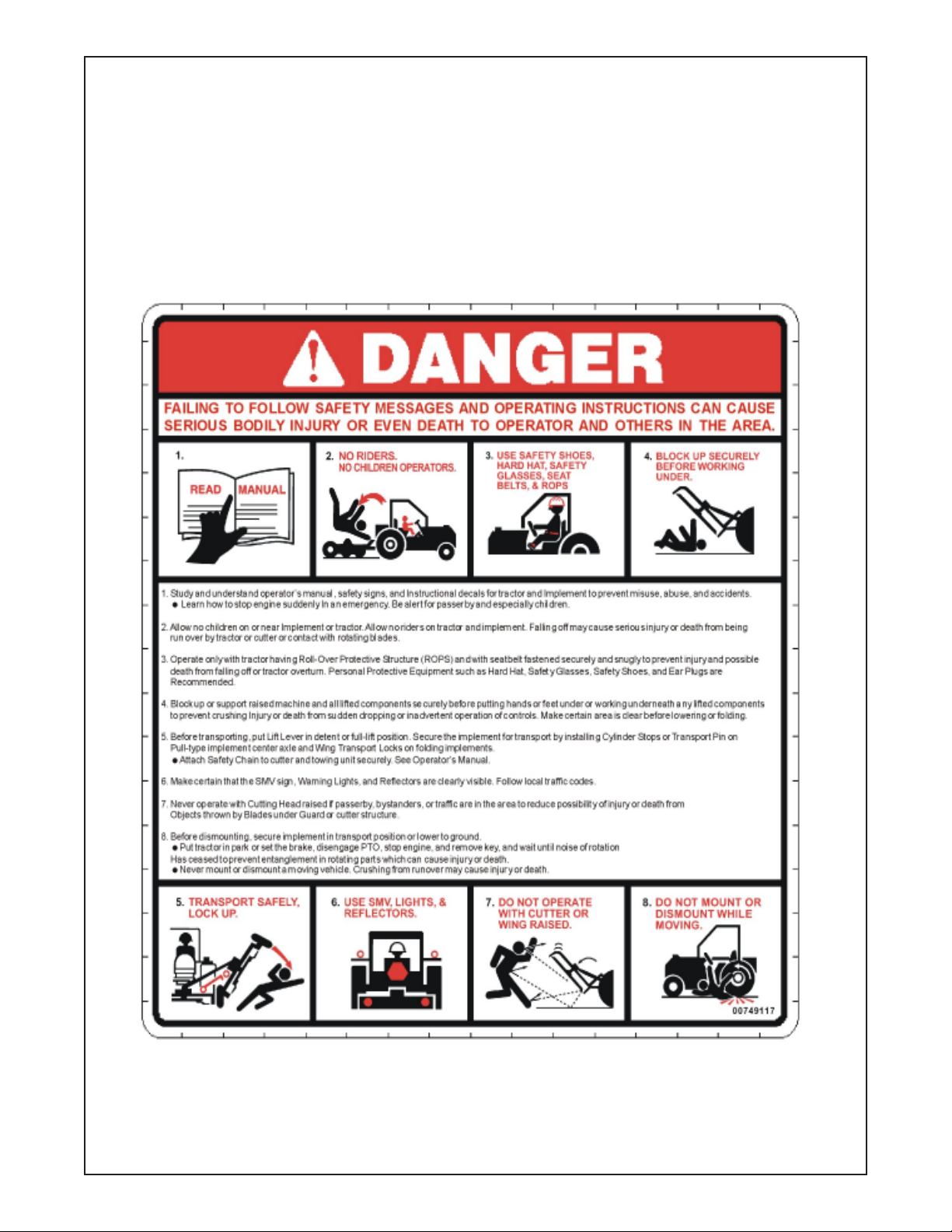
CAUTION! The lowest level of Safety Message; warns of possible injury. Decals
located on the Equipment with this Signal Word are Black and Yellow.
WARNING! Serious injury or possible death! Decals are Black and Orange.
DANGER! Imminent death/critical injury. Decals are Red and White. (SG-1)
Axtreme Boom (Asy. Man.) 07/06
© 2006 Alamo Group Inc.
Section 1 - 2
Page 11
Safety Section
PELIGRO!
Si no lee Ingles, pida ayuda a alguien que si lo lea para que le
traduzca las medidas de seguridad. (SG-3)
!LEA EL INSTRUCTIVO!
READ, UNDERSTAND, and FOLLOW the following Safety
Messages. Serious injury or death may occur unless care is
taken to follow the warnings and instructions stated in the Safety
Messages. Always use good common sense to avoid hazards.
(SG-2)
PELIGRO!
Si no lee Ingles, pida ayuda a alguien que
si lo lea para que le traduzca las medidas
de seguridad. (SG-3)
INSTRUCTIVO!
!
LEA EL
WARNING!
WARNING!
DANGER!
WARNING!
Perform service, repairs and lubrication according to the maintenance section. Ensure the unit
is properly lubricated as specified in the lubrication schedule and all bolts and nuts are properly
torqued. Failure to properly service, repair and maintain this Implement in good operating
condition could cause component failure and possible serious injury or even death. (SG-35)
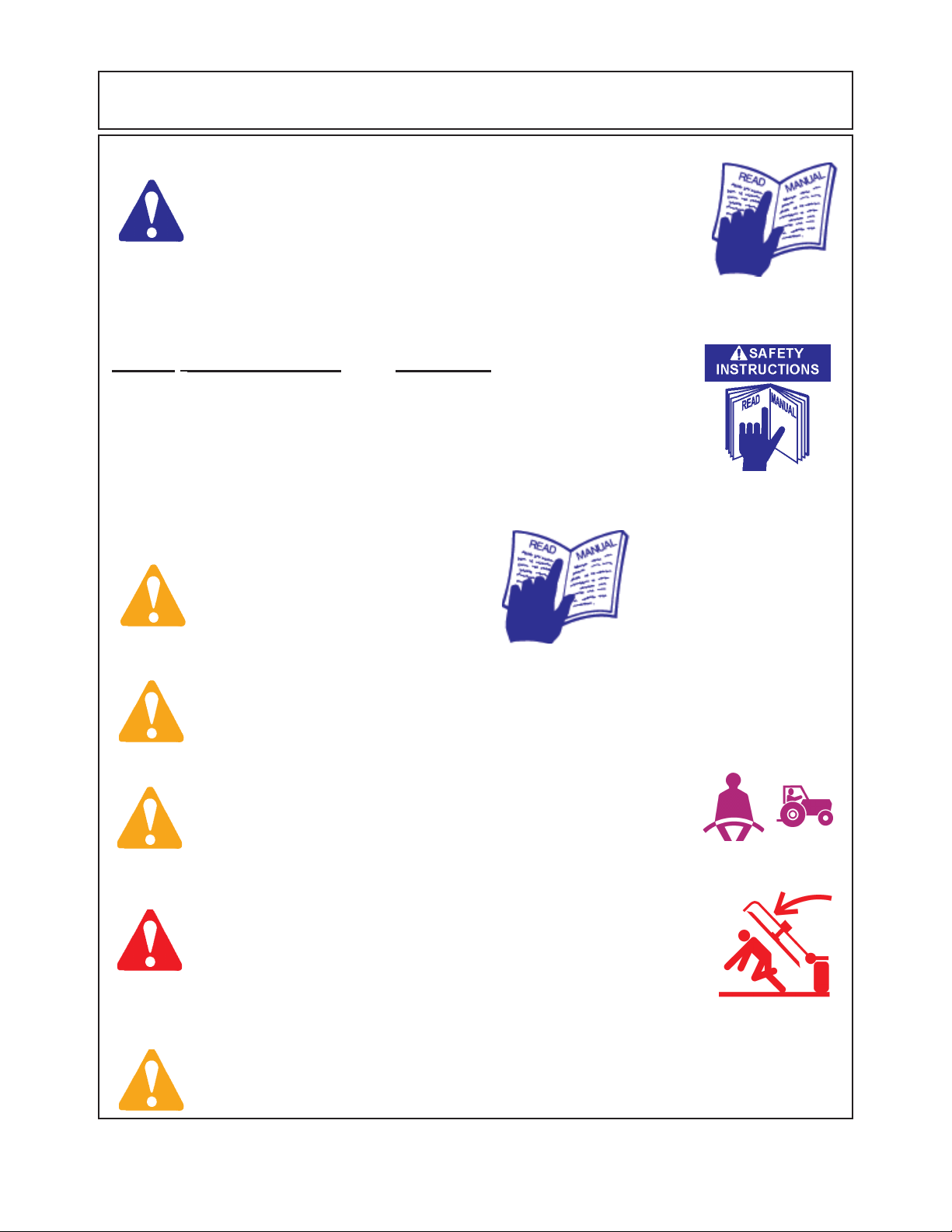
Operate this Equipment only with a Tractor equipped with an
approved roll-over-protective system (ROPS). Always wear seat
belts. Serious injury or even death could result from falling off the
tractor--particularly during a turnover when the operator could be
pinned under the ROPS. (SG-7)
Never work under the Implement, the framework, or any lifted component unless the Implement is securely supported or blocked up to
prevent sudden or inadvertent falling which could cause serious injury
or even death. (SG-14)
Use caution and wear protective gloves when handling sharp objects such as blades, knives,
and other cutting edges. Be alert to worn component surfaces which have sharp edges. Sharp
surfaces can inflict severe laceration injuries if proper hand protection is not worn. (SG-37)
Axtreme Boom (Asy. Man.) 07/06
© 2006Alamo Group Inc.
Section 1 - 3
Page 12
Safety Section
WARNING!
WARNING!
WARNING!
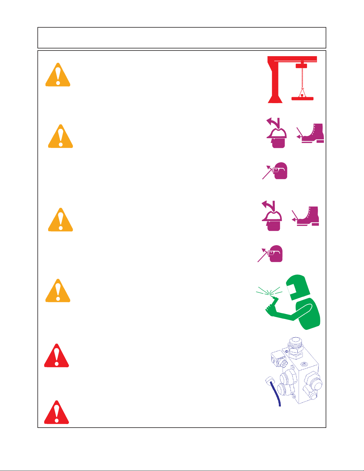
Many of the parts are heavy and require lifting assistance. Do not try to
lift the heavy parts by yourself. Get help from another employee or from
an overhead crane.
The operator and all support personnel should wear hard hats,
safety shoes, safety glasses, and proper hearing protection at all
times for protection from injury including injury from items thrown by
the equipment. (SG-16)
Always wear safety shoes with steel toes when working on this equipment.
It is recommended that the safety shoes have metatarsal guards.
WARNING!
DANGER!
DANGER!
When welding use Welding hood with the appropriate OSHA required
protective lens, welding apron, and welding gloves.
Always disconnect the wire leads from the mower valve solenoid before
performing service on the Tractor or Mower. Use caution when working
on the Tractor or Mower. Tractor engine must be stopped before
working on Mower or Tractor. The Mower Blades could inadvertently be
turned on without warning and cause immediate dismemberment, injury
or death. (SBM-12)
Never run the tractor engine in a closed building or without adequate
ventilation. The exhaust fumes can be hazardous to your health.
Axtreme Boom (Asy. Man.) 07/06
© 2006 Alamo Group Inc.
(SG-23)
Section 1 - 4
Page 13
Safety Section
DANGER!
WARNING!
DANGER!
Before starting the mower make sure the area is clear and the floor has
been swept. The mower blade can throw objects several hundred feet.
Thrown objects could damge property or cause severe bodily injuries even
death.
Make certain that the “Slow Moving Vehicle” (SMV) sign is installed in
such a way as to be clearly visible and legible. When transporting the
Equipment use the Tractor flashing warning lights and follow all local traffic
regulations.
Start tractor only when properly seated in the Tractor seat. Starting a
tractor in gear can result in injury or death. Read the Tractor operators
manual for proper starting instructions. (SG-13)
(SG-6)
DANGER!
WARNING!
DANGER!
Do not operate this Equipment with hydraulic oil leaking. Oil is
expensive and its presence could present a hazard. Do not check for
leaks with your hand! Use a piece of heavy paper or cardboard. Highpressure oil streams from breaks in the line could penetrate the skin
and cause tissue damage including gangrene. If oil does penetrate the
skin, have the injury treated immediately by a physician knowledgeable and skilled in this procedure. (SG-15)
Always read carefully and comply fully with the manufacturers instructions when handling oil, solvents, cleansers, and any other chemical
agent. (SG-22)
All Safety Shields, Guards and Safety devices including
(but not limited to) - the Deflectors, Chain Guards, Steel
Guards, Gearbox Shields, PTO integral shields , and
Retractable Door Shields should be used and maintained in good working condition. All safety devices
should be inspected carefully at least daily for missing
or broken components. Missing, broken, or worn items
must be replaced at once to reduce the possibility of
injury or death from thrown objects, entanglement, or
blade contact. (SGM-3)
Axtreme Boom (Asy. Man.) 07/06
© 2006Alamo Group Inc.
Section 1 - 5
Page 14
Safety Section
DANGER!
DANGER!
WARNING!
NEVER use drugs or alcohol immediately before or while operating the
Tractor and Implement. Drugs and alcohol will affect an operator’s
alertness and coordination and therefore affect the operator’s ability to
operate the equipment safely. Before operating the Tractor or Implement, an operator on prescription or over-the-counter medication must
consult a medical professional regarding any side effects of the medication that would hinder their ability to operate the Equipment safely.
NEVER knowingly allow anyone to operate this equipment when their
alertness or coordination is impaired. Serious injury or death to the
operator or others could result if the operator is under the influence of
drugs or alcohol. (SG-27)
Operate the Tractor and/or Implement controls only while properly seated
in the Tractor seat with the seat belt securely fastened around you.
Inadvertent movement of the Tractor or Implement may cause serious
injury or death. (SG-29)
Engine Exhaust, some of its constituents, and certain vehicle
components contain or emit chemicals known to the state of California
to cause cancer and birth defects or other reproductive harm. (SG-30)
WARNING!
WARNING!
WARNING!
WARNING!
Battery posts, terminals and related accessories contain lead and lead
compounds, chemicals known to the state of California to cause
cancer and birth defects or other reproductive harm. Wash Hands after
handling. (SG-31)
Use extreme caution when getting onto the Implement to perform repairs, maintenance and
when removing accumulated material. Only stand on solid flat surfaces to ensure good
footing. Use a ladder or raised stand to access high spots which cannot be reached from
gound level. Slipping and falling can cause serious injury or death. (SG-33)
Avoid contact with hot surfaces including hydraulic oil tanks, pumps, motors, valves and
hose connections. Relieve hydraulic pressure before performing maintenance or repairs.
Use gloves and eye protection when servicing hot components. Contact with a hot surface
or fluid can cause serious injury from burns or scalding. (SG-34)
Avoid contact with hot surfaces of the engine or muffler. Use gloves and eye protection
when servicing hot components. Contact with a hot surface or fluid can cause serious injury
from burns or scalding. (SG-38)
Axtreme Boom (Asy. Man.) 07/06
© 2006 Alamo Group Inc.
Section 1 - 6
Page 15

Section 2
Axtreme Boom
Model
Specifications
Axtreme Boom - Asy Man (07/06)
© 2006 Alamo Industrial
Section 2 - 1
Page 16

SPECIFICATIONS - AXTREME BOOM
READ THIS BEFORE BEGINNING ASSEMBLY:
The Axtreme Boom has electronic components:. The electronic components can
be damaged if care is not taken when performing repairs, testing and/or during assembly.
DO NOT
1. DO NOT short any wires across or allow them to be shorted out.
2. DO NOT attempt to jump across any wires or supply them with alternate power source.
3. DO NOT install higher rated fuses than are recommended by manufacturer.
4. DO NOT do any welding on unit unless the computer modules are unplugged first, this is to prevent a power
surge going into modules (THIS IS VERY IMPORTANT). This could also apply to the tractor components.
Check Tractors repair guide for specific instruction about tractor model and type.
5. DO NOT attempt to repair or adjust a component that is not intended to be repaired, example sealed
components as there are no serviceable components inside.
6. DO NOT let anyone attempt any testing or repairs unless they are an experienced and qualified techni-
cian. Technicians must have proper tools, gauges, meters etc. to perform proper diagnosis and/or repairs.
7. DO NOT perform any assembly or repairs with dirty tools or in dirty work area. When working on hydraulic
components keeping system clean and free of contamination is important.
8. DO NOT start or engage system if the oil level is not at the proper level or condition. Never start or run
unit low or out of oil.
9. DO NOT install / add any oil unless you know it is the correct type and the container is clean. Make certain
the oil is not contaminated with dirt or any liquid.
1. Pump Specifications:
Body Construction.....................................................................Cast Iron
Control Valve Type.................................................................... Direct Acting, Pilot Operated
Control Valve Relief................................................................... 3000 PSI
Driveshaft Type......................................................................... 1" X 15 Spline
Driveshaft Torque Rating............................................................ 371 ft. lbs.
Pressure Rating (Maximum).......................................................3000 PSI
Pump Type...............................................................................Gear
Pump Gear Width..................................................................... 2 inch
Pump Efficency Flow Rate (Approx)............................................85 % of G.P.M. is Acceptable
Speed Rating (Maximum)...........................................................2400 RPM
Nominal Displacement (Per Revolution)....................................... 5.1 Cu. In.
Output @ 1800 RPM.(Operating RPM)........................................37.5 G.P.M.
Output @ 2400 RPM.(Maximum RPM)........................................ 51 G.P.M.
Horsepower Rating (Maximum Conditions)................................... 90 HP
Rotation Direction (Viewed from Top of Deck................................ Clockwise
Motor Start / Stop Time............................................................. 6 Seconds (Approx)
Tank Capacity Required.............................................................17.5Gallons
Oil Type................................................................................... See Oil Chart
Oil Temperature (While Operating).............................................. 70 Deg, (F) Above Ambient
Axtreme Boom - Asy Man (07/06)
© 2006 Alamo Industrial
Section 2 - 2
Page 17

SPECIFICATIONS - AXTREME BOOM
2. Fifty Inch (50") Cutting Head Specifications:
Blade / Motor Rotation (Looking down from Top of Deck)...............Clockwise
Blade Tip Speed........................................................................18,850 FPM / 210 MPH
Blade carrier Type..................................................................... Pan or 3 Leaf bar Option
Blade Pan Blade Qty.................................................................2 Blade or 3 Blade Option
Blade Bar Blade Qty.................................................................. 2 Blades
Blade Cutting Width (Overall)......................................................50 inches.
Deck Construction.....................................................................Formed and Welded Steel
Deck Material........................................................................... 10 Gauge
Deck Weight.............................................................................725 lbs.
Spindle ....................................................................................4.5" by 9" Heat Treated Alloy
Spindle Bearing.........................................................................Tapered Roller Bearings
Spindle Lubrication....................................................................Grease (Pumped In)
Motor Type...............................................................................Gear
Motor Gear Width......................................................................2-1/2"
Motor Speed (Maximum)............................................................2400 RPM
Motor Pressure (Maximum)........................................................3000 PSI
Motor Rated Pressure ...............................................................3000 PSI
Motor Rated Flow......................................................................38 GPM
Motor Displacement.................................................................. 6.375 Cu. Inches
3. Sixty Inch (60") Rotary Mower Head:
Blade / Motor Rotation (Looking down from Top of Deck)...............Clockwise
Blade Tip Speed........................................................................18,000 FPM / 205 MPH
Blade Carrier Type.....................................................................2 Leaf bar Option
Blade Bar Blade Qty.................................................................. 2 Blades
Blade Cutting Width (Overall)......................................................60 inches.
Deck Construction.....................................................................Formed and Welded Steel
Deck Material........................................................................... 10 Gauge
Deck Weight.............................................................................818 lbs.
Spindle ....................................................................................4.5" by 9" Heat Treated Alloy
Spindle Bearing.........................................................................Tapered Roller Bearings
Spindle Lubrication....................................................................Grease (Pumped In)
Motor Type...............................................................................Gear
Motor Gear Width......................................................................2.25"
Motor Speed (Maximum)............................................................2500 RPM
Motor Pressure (Maximum)........................................................3250 PSI
Motor Rated Pressure................................................................3000 PSI
Motor Rated Flow......................................................................38 GPM
Motor Displacement.................................................................. 8.1 Cu. Inches
4. Rotary Head Torque Specification:
Motor to Spindle Housing...........................................................100 ft. lbs.
SPindle to Deck........................................................................425 ft. lbs.
Spindle Bearing Pre-Load...........................................................25 in. lbs. Rolling Torque
Blade Bar Leaf Bars. ( 1-1/4" Bolts)............................................ 2000 ft. lbs.
Blade Bolts ..............................................................................400 ft. lbs.
Blade Bar to Spindle..................................................................400 ft. lbs.
Axtreme Boom - Asy Man (07/06)
© 2006 Alamo Industrial
Section 2 - 3
Page 18
SPECIFICATIONS - AXTREME BOOM
1234567
1
7
1234567
8
7
7
8
8
8
8
3
123
123
123
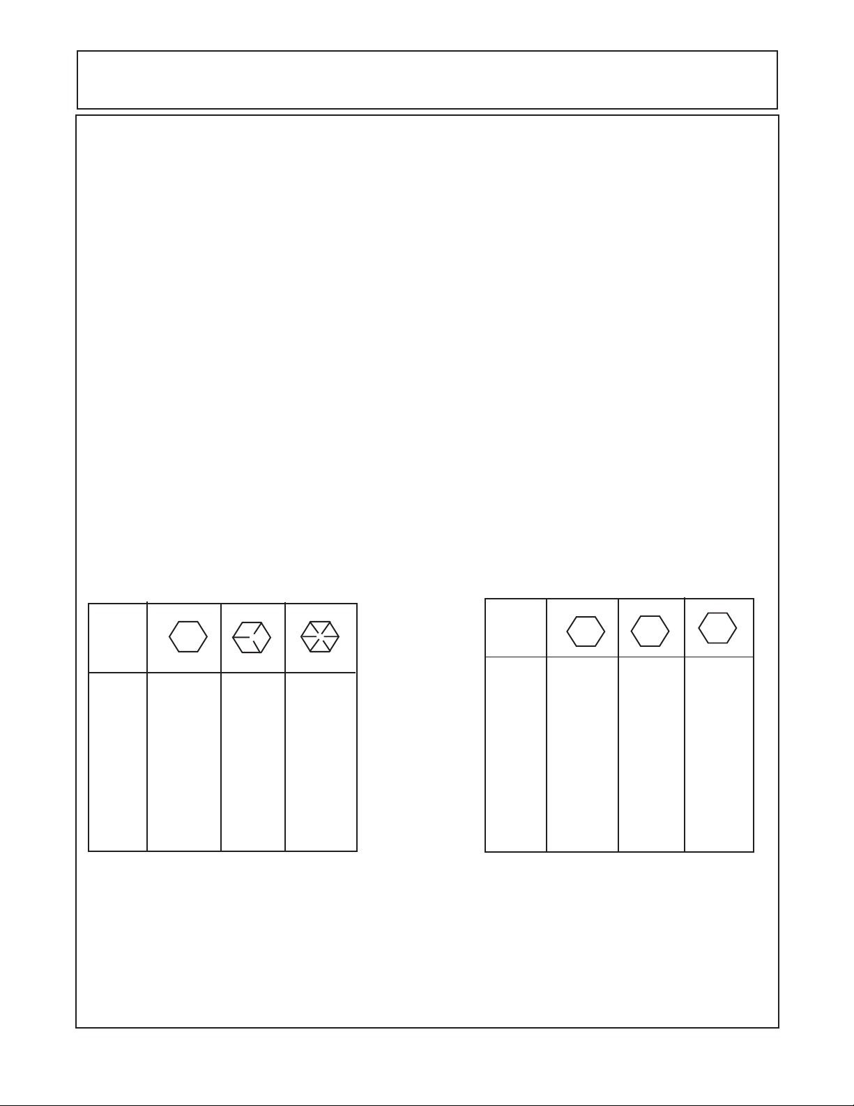
5. Control Valve: 5 Spool used with Rotary Heads w/ Door
Valve Type................................................................................Open Center 5 Spool
Valve Control (Manual Standard)................................................. Remote Cable Control
Valve Control (Electonic Joystick Optional)..................................Joystick Electronic Control
Pressure (Maximum)................................................................. 3500 PSI
Flow (Maximum)....................................................................... 20 GPM
Main Relief............................................................................... Direct Acting: 3000 PSI: Adjustable
FilterType.................................................................................Return Side
Filter Size.................................................................................10 Micron
Bushings..................................................................................Greasable Steel
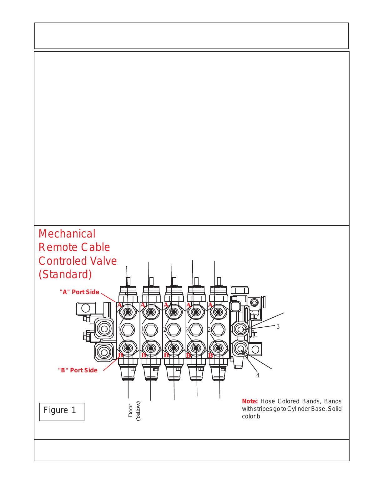
6. Valve Ports: ( See Figure 1 & 2)
"A" Port...........Valve Ports designated as "A" Ports connect to the Rod End of the Swing and Lift Cyl, to the
Barrel End of the Dipper Cyl, to the Barrel End of Tilt Cyl and to Barrel End of the Door Cyl.
"B" Port......... Valve Ports designated as "B" Ports connect to the Barrel End of Swing and Lift Cyl, to the
Rod End of the Dipper Cyl, to the Rod End of the Tilt Cyl and to the Rod End of the Door Cyl.
Mechanical
Remote Cable
Controled Valve
(Standard)
"A" Port Side
"B" Port Side
Figure 1
Door
Tilt
(Red)
Dipper
(Y ellow / White)
Tilt
2
23456
23456
23456
AAAA
1
B
234567
A
1
BB
2
Door
(Yellow)
(Red / White)
Lift
(Blue)
(Orange / White)
234567
234567
2
BB
Dipper
Lift
(Orange)
(Blue / White)
Swing
(Green / White)
234567
234567
2
Swing
Pressure Supply (Port P1)
3
4
Return (Port T2)
Note: Hose Colored Bands, Bands
with stripes go to Cylinder Base. Solid
color bands go to Cylinder rod end.
(Green)
Axtreme Boom - Asy Man (07/06)
© 2006 Alamo Industrial
Section 2 - 4
Page 19
SPECIFICATIONS - AXTREME BOOM
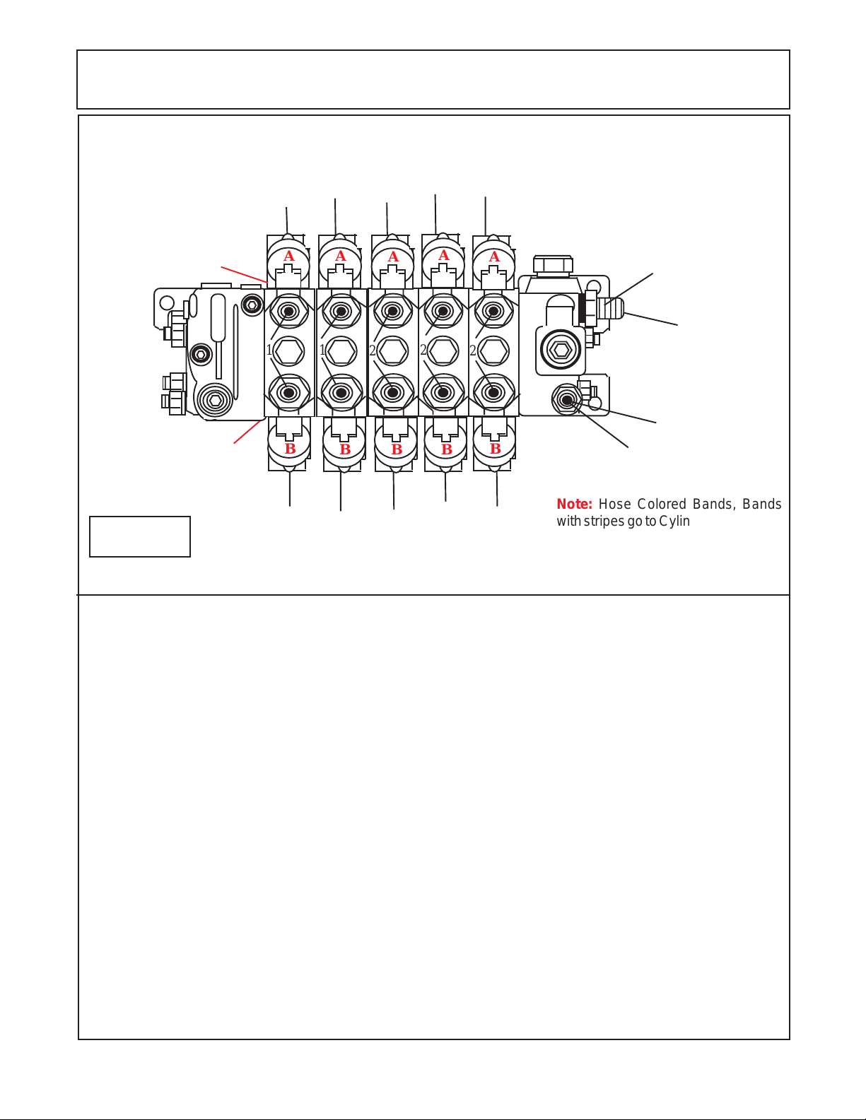
12
12
12
3
Joystick
Electronic
Controled Valve
(Optional)
"A" Port Side
2
"B" Port Side
Figure 2
Door
A A
1
B
Tilt
(Yellow)
(Red / White)
1
B B B
Door
Tilt
(Y ellow / White)
Dipper
A
2
(Red)
Lift
(Orange)
(Blue / White)
A
2
Lift
(Blue)
Dipper
(Orange / White)
2
Swing
(Green)
A
B
Swing
(Green / White)
Pressure Supply
(Port P1)
3
4
Return (Port T2)
Note: Hose Colored Bands, Bands
with stripes go to Cylinder Base. Solid
color bands go to Cylinder rod end.
7. Valve Sections Function:
Mechanical Control Vale (See Figure 1)
Spool Cylinder Function Pressure
"B" "A" "A" "B"
1 Swing Back Forward 2750 PSI 2750 PSI
2 Lift Up Down 2750 PSI 1160PSI
3 Dipper Out In 2750 PSI 1160PSI
4 Tilt Up Down 2750 PSI Main Relief Main Relief
5 Door In-Open Out-Closed Main Relief Main Relief
Electronic Control Vale (See Figure 2)
Spool Cylinder Function Pressure
"B" "A" "A" "B"
1 Swing Back Forward 2750 PSI 2750 PSI
2 Lift Up Down 1160 PSI 2750 PSI
3 Dipper Out In 1160 PSI 2750 PSI
4 Tilt Up Down 2750 PSI Main Relief
5 Door In-Open Out-Closed 2750 PSI 2750 PSI
Axtreme Boom - Asy Man (07/06)
© 2006 Alamo Industrial
Section 2 - 5
Page 20
SPECIFICATIONS - AXTREME BOOM
8. Hose End Fitting Torque Specification:
Hose End Type: 37 Degree Angle End Steel Hose End Fittings*
Dash Nominal Cyl. Torque Torque
Size Size (in.) in. lbs. ft .lbs.
-4 1/4" 140 12
-6 3/8" 230 19
-8 1/2" 450 38
-10 5/8" 650 54
-12 3/4" 900 75
-16 1" 1200 100
-20 1-1/4" 1600 133
-24 1-1/2" 2000 167
-32 2" 2800 233
* Straight Threads do not always seal better when higher torgues are used. Too much torque
causes distortion and may lead to leakage. DO NOT over torque fittings and DO NOT allow any
contaminants to enter system through fittings when installing them.
9. TORQUE VALUES - BOLTS:
Maximum Torque per Bolt Size and Grade, Ft lbs & (Nm)
IMPORTANT ! Listed below IS BOLT TORQUE and NOT APPLICATION TORQUE, Component
Application Torque will vary dependimg on what is bolted down and the type material (Metal) that is
being bolted together. Thread condition and lubrication will vary Torque settings.
Bolt
Dia.
inch
1/4
5/16
3/8
7/16
1/2
9/16
5/8
3/4
7/8
1
1-1/8
1-1/4
Inche Sizes
2 (B)
Plain Head
Not Used
Not Used
Not Used
35 (47)
55 (75)
75 (102)
105 (142)
185 (251)
160 (217)
250 (339)
330 (447)
480 (651)
5 (D)
3 Dashes
85 (115)
130 (176)
170 (230)
300 (407)
445 (603)
670 (908)
910 (1234)
1250 (1695)
10 (14)
20 (27)
35 (47)
55 (75)
8 (F)
6 Dashes
14 (19)
30 (41)
50 (68)
80 (108)
120 (163)
175 (230)
240 (325)
425 (576)
685 (929)
1030 (1396)
1460 (1979)
2060 (2793)
ALWAYS
CHECK
MARKINGS
ON
TOP
OF
BOLT
HEAD
OR
OTHER
BOLT
DESCRIP-
TIONS
Bolt
Dia.
mm
6
8
10
12
14
16
18
20
22
24
27
30
33
36
Metric Sizes
4.8
5
11
20
37
60
92
118
160
215
285
450
600
800
900
8.8
7
20
40
70
100
155
216
270
330
500
875
1200
1600
2100
10.8
12
25
58
105
140
200
280
355
430
700
1000
1700
2300
3000
Axtreme Boom - Asy Man (07/06)
© 2006 Alamo Industrial
Section 2 - 6
Page 21

Section 3
Axtreme Boom
Tractor Preperations
NOTE: This shows a basic mount for the frame installation and may not be the
same for your tractor model. The way the frame mounts to the tractor
components can vary with tractor model. See the installation drawings shipped
with the unit for the specific tractor type mount and hardware components. IN
SOME CASES THE MANUAL INSTRUCTION MAY VARY FROM THE
INSTALLATION DRAWING INSTRUCTION, THE INSTALLA TION DRAWING INSTRUCTIONS WILL OVERRIDE THE ASSEMBLY MANUAL INSTRUCTIONS WHICH ARE BASIC. THE INSTALLATION DRAWINGS ARE
FOR A SPECIIFIED TRACTOR.
Axtreme Boom (Asy. Man) 07/06
© 2006 Alamo Group Inc.
Section 3 - 1
Page 22

General Information / Installation Requirements
General Information:
The tools you will need at the assembly site are as follows:
1. Welding equipment (including correct head gear, eye shields, and protective clothing.)
2. Impact wrench or socket and ratchet set.
3. Rubber mallet.
4. Box-end, Allen, and crescent wrenches.
5. Alignment pins.
6. Phillips and plain-head screwdrivers.
7. Forklift or hydraulic floor jacks with rolling back boards.
8. Over head hoist and floor jacks
9. Jack Stands and/or other support devices that are strong enough to support tractor and components
10. Multidirectional Levels.
11. Paint Scraper.
12. Hydraulic Filter Buggy or Cart.
13. Safety shoes, safety glasses, and gloves.
14. A hard hat should be worn by anyone working under any raised component.
Remember to follow each step closely and cautiously. Be aware of all support personnel at all times.
Keep the assembly area as clean as possible; clean up all spills when they occur. An uncluttered assembly area
and a crew that is sensitive to the hazards involved in putting this implement together will help prevent accidents.
Keep all unauthorized personnel from the area. Do not allow children near the assembly site nor allow them on or
near the tractor after assembly. There is no safe place for anyone except the operator on the tractor and those
assisting with the assembly.
To help you assemble your new Unit and mount it to your tractor, a detailed assembly instruction
Manual is being provided with the mount kit to provide detailed instructions and part numbers. Please
consult this document for specific information. When needed, you can get additional information or
clarification from Your Dealer or Alamo Group Customer Service.
This publication provides general information and may not specifically be for your case or tractor, but,
in connection with the assembly drawings that are sent with the mount kit, this publication offers you some
valuable assistance - please read it thoroughly and use it with your assembly drawings and other
publications. Other publications may include, operators manual, parts manual, service manual or any other
publication sent by manufacturer. Keep all publications together for future reference.
These mount kits are made for selected tractors with standard configurations. Only the noted
options and tire sizes listed in the Mounting Specifications will work with these mount kits. Other options,
front axles, or different tire sizes may prevent the mount kit from fitting your nonstandard tractor. Alamo
Group cannot take responsibility for these problems or any modifications made to the unit.
Throughout these instructions, references are made to right or left directions. Right and left are
determined by sitting on the tractor seat and facing the direction of travel forward always.
This is the Safety-Alert symbol. When you see this symbol on your machine or in these
instructions, be alert to the potential for personal injury. Follow recommended precautions
DANGER!
and safe operating practices.
DANGER!
A signal word - DANGER, WARNING, or CAUTION - is used with the Safety Alert symbol.
DANGER identifies the most serious hazards.
Axtreme Boom (Asy. Man) 07/06
© 2006 Alamo Group Inc.
Section 3 - 2
Page 23
General Information / Installation Requirements
WARNING! Safety signs with signal word WARNING are typically used to point out more
serious hazards.
CAUTION! General precautions are listed on CAUTION safety sign. CAUTION also calls
attention to safety messages in these instructions.
WARNING!
Disconnect the negative lead (ground) from the battery terminal to prevent any
damage to the electrical system.
LEVELING TRACTOR:
TRACTOR MUST be on level ground before assembly is begun. The tractor must be level, All tires
must have the proper amount of air in them as per tire and/or Tractors manufactures recommendations.
DO NOT level tractor by over inflating tires. The tractor can be leveled by jacking it up and putting it on
jack stands if needed. Tractor should be kept at ride/operation height when mounting unit, this will insure
that the components are mounted at the correct height.
Axtreme Boom (Asy. Man) 07/06
© 2006 Alamo Group Inc.
Section 3 - 3
Page 24

General Information / Installation Requirements
Replacement Oil Filter
Included in the packing box of this unit is a replacement filter element for filter assembly in the tank.
This Mower unit's hydraulic components have been carefully cleaned and packaged at the factory to
prevent contamination from entering the system. However, dust and dirt particles may enter into the
sealed components through transportation, handling, rain, or just sitting in a dirty or harsh environment.
Therefore to assure that the hydraulic system is properly clean, please prepare the area where the unit
is to be assembled. The area should be on a hard concrete floor that has been swept clean of all dust
and contaminants. Unpacked the Mower unit carefully so that the seals on the hydraulic components
are not broken or pulled off.
WARNING!
WARNING!
WARNING!
Before attempting to assemble the mower to the tractor, move the tractor to a clean
solid surface, preferably a concrete shop surface with an over head crane. The crane
should have a rated capacity to lift the heaviest component or assembly. A 5-ton crane
is recommended for the assembly work. If a smaller crane is used, be sure not to
exceed the rated capacity of the crane.
Q Always follow all OSHA crane operating and inspection rules, regulations,
inspection requirements, and recommended practices when using the crane.
Q Never work under any component that is lifted by the crane.
Wear personal protective equipment when assembling the mower. As a minimum that
should include:
Q Safety Glasses Q Safety Shoes Q Gloves
Q Hard Hat Q Hearing Protection Q Welding Helmet
Before attempting to assemble ensure that the tractor engine is off and the tractor
transmission is in the park position with the parking brake engaged.
Q Remove the engine key and keep it in your pocket to prevent inadvertent
starting or movement of the tractor.
Q Place wheel blocks in front and behind the tractor wheels to prevent the tractor
from moving.
Q Never attempt to start the tractor unless properly seated in the tractor seat
with the seat belt fastened around you.
Q Never attempt to operate the tractor and mower controls unless seated in
the tractor seat with the seat belt fastened around you.
WARNING!
WARNING!
Axtreme Boom (Asy. Man) 07/06
© 2006 Alamo Group Inc.
Securely block up and support the tractor before attempting to loosen and move the
tires. Failure to properly block up the tractor can result in the tractor to suddenly move
or fall, crushing you or another worker.
Q Never work under any raised component or any component that is not
securely blocked up or supported.
Many components of this mower are very heavy and must be handled by proper
material handling equipment. Do not lift components that weight over 50lbs by
yourself.
Q Use an overhead crane, forklift, or other coworkers to lift heavy items. Ensure
lifted components are securely supported.
Q Never walk or work under a lifted component.
Section 3 - 4
Page 25
General Information / Installation Requirements
WARNING!
WARNING!
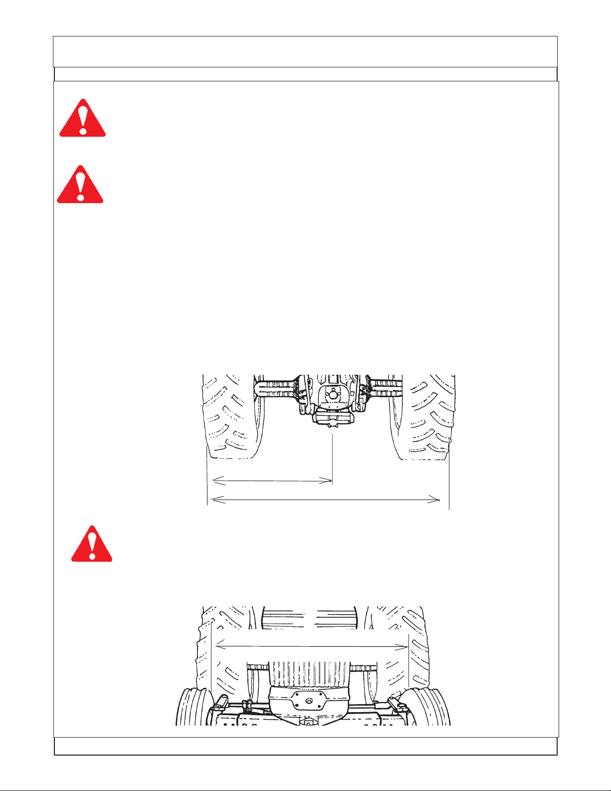
TRACTOR PREPARATION (FIGURE 1 & 2)
1. Temporally remove ROPS and fenders from tractor axle. Move left rear tire out so that it is 50 inches
from the outside of left rear tire to the center of tractor. Then move the right rear tire out so that it is 96
inches between the outside of the left and right rear tires. Refer to your tractor’s Operator’s Manual for
instructions on Rear Wheel Adjustment for your particular tire. FIGURE 1. Hydraflate rear left tire as
much as needed for stability but stay in factory-recommend limit.
Use extreme care when moving, handling or adjusting the tractor tires. The tires are
extremely heavy and could fall and crush you
Q Use an overhead crane or forklift to move the tires.
Q Properly fasten the tires to the material handling equipment to prevent the tire
from falling.
The hydraulic oil is under high pressure and a hydrauli leak can cause oil to be injected
under the skin.
Q Before starting the tractor ensure all hydraulic connections have bee tightened
Q Never check for leaks with your hands. Use a piece of wood or cardboard to
check for the leak making sure your hands and face are kept away from the
leak area.
Q Repair any leaks before operating the equipments
Q Clean up all oil that has leaked according to the requirements of the oil supplier.
Oil residue on the ground can result in unjury from slipping or falling.
FIGURE 1
50"
96"
WARNING: Never operate the tractor with a loose wheel rim or disc. Always tighten nuts
to the specified torque and at the recommended intervals.
2. Extend front wheels out so that it is 55" inches between the inside of the tires. This will allow
no interference between tire and front mount bracket. FIGURE 2.
FIGURE 2
55"
Axtreme Boom (Asy. Man) 07/06
© 2006 Alamo Group Inc.
Section 3 - 5
Page 26
General Information / Installation Requirements
Tractor, Area Cleanliness
The Tractor, all tools and work area must be clean of dirt and debris when assembling any hydraulic
components. DO NOT leave any hydraulic component open to the elements. DO not use any containers
for fluids that are not clean and free of any other liquids. DO NOT use rags/cloth that has lint or fuzz on
them when working on hydraulic components. Keep all hoses capped until you are ready to connect
them.
Cleaning Boom and mower componets (electronics)
The units Components are designed to be water resistant. But the sealing can be damaged by Pressure
Washers, Steam Cleaners, Solvents or any other harsh chemical that would be used to clean the units
components. It is important to keep all electrical connections and components sealed and dry. When
washing and cleaning this unit it should be done with a non corrosive soap and low pressure spray of
water. It is recommended that all exposed electronic components be covered and protected from excess
moisture.
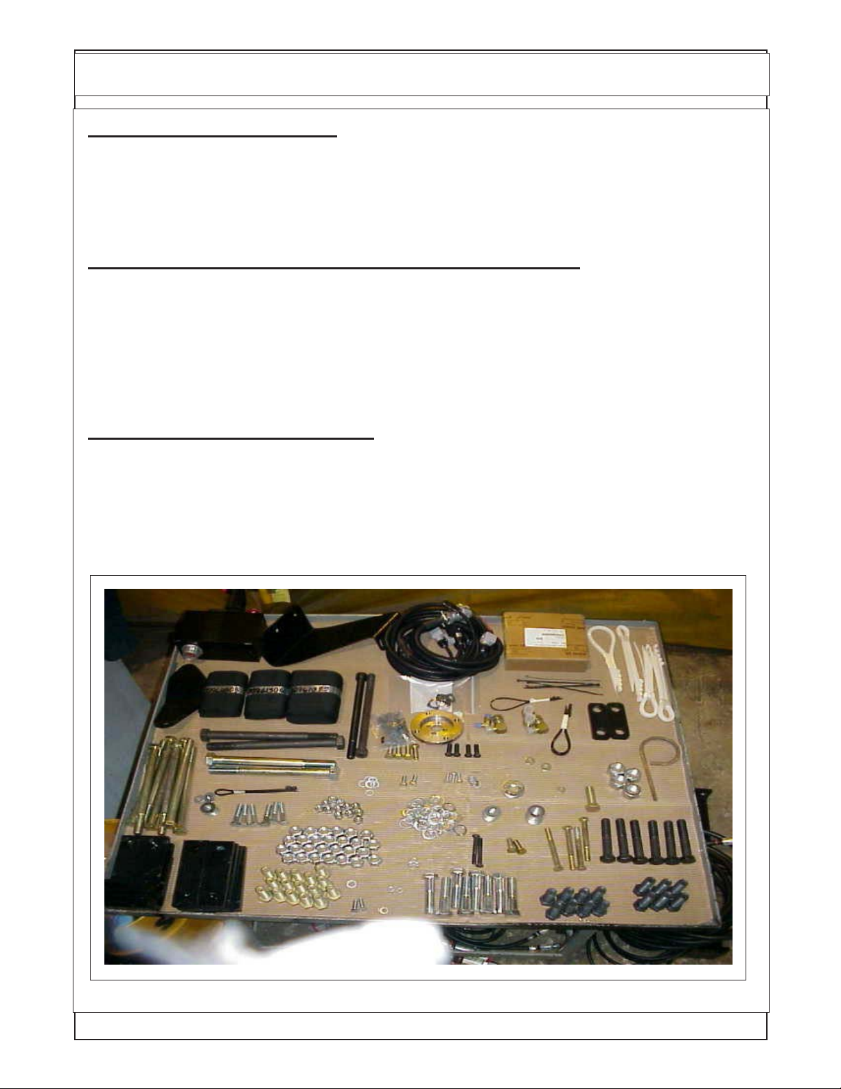
Lay Out Components in Display. It is helpful to lay out the component in as neat a display
as possible. Lay out the Bolts according to size and length. Lay out the Nuts and washer by size. This
will allow you to see how many of each part as you use them and help to identify any missing parts. (See
figure 6) See Mount Kit Specification and Component Identification Section to help ID Components.
All the component that are received should be check and sorted as to what they are.
Shown below is a general example of the components laid out, this is not a lay out of
the components in this mount kit.
Axtreme Boom (Asy. Man) 07/06
© 2006 Alamo Group Inc.
Section 3 - 6
Page 27

General Information / Installation Requirements
WARNING
DO NOT WELD On This Unit During or After Installation:
DO NOT WELD any components or items on this unit after the installation of the
maverick Boom has begun. The Maverick Boom uses electronic modules and components that could be damaged by welding. Before doing any welding ALL ELECTRONIC
MODULES AND DISPLAY COMPONENTS MUST BE UNPLUGGED. Check the Tractors
Opertion, Repair, Service or any other manual from the tractor manufacturer of the tractor
to find any special electronic or special proedures about the tractor electronics. Taking
a few minutes to check could save you from a major damage to the electronics.
Axtreme Boom (Asy. Man) 07/06
© 2006 Alamo Group Inc.
Section 3 - 7
Page 28

NOTES
Axtreme Boom (Asy. Man) 07/06
© 2006 Alamo Group Inc.
Section 3 - 8
Page 29

Section 4
Axtreme Boom
Battery, Exhaust
&
Fuel Tank
Modification
With
Main Frame
Inst allation
NOTE: This shows a basic mount for the frame installation and may not be the
same for your tractor model. The way the frame mounts to the tractor components can vary with tractor model. See the installation drawings shipped with the
unit for the specific tractor type mount and hardware components. IN SOME
CASES THE MANUAL INSTRUCTION MAY VAR Y FROM THE INSTALLATION DRA WING INSTRUCTION, THE INSTALLATION DRA WING INSTRUCTIONS WILL OVERRIDE THE ASSEMBLY MANUAL INSTRUCTIONS WHICH
ARE BASIC. THE INSTALLATION DRAWINGS ARE FOR A SPECIIFIED
TRACTOR.
Axtreme Boom (Asy. Man) 07/06
© 2006 Alamo Group Inc.
Section 4 - 1
Page 30
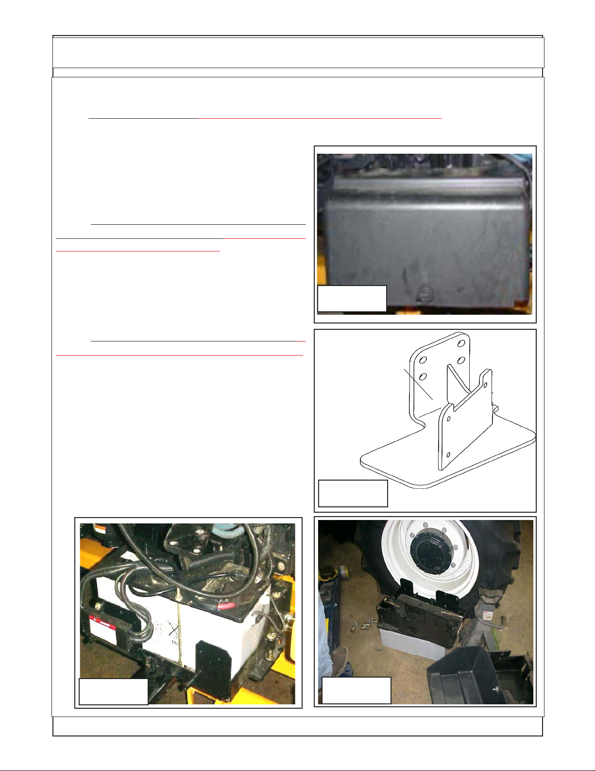
Battery Holder Relocation
Battery Holder Relocation:
1. The Battery Relocation (If Required, See Assembly Drawings sent with unit). The battery holder is
located on the RH side of the tractor (See Figure 1) . It will have to be relocated. The mount kit will include
a battery relocation kit. The battery relocation kit includes a mounting bracket (See Figure 2)
that will relocate the battery tray farther to the rear.
This is done so the Boom Swing will not hit battery
when in the transport position. The RH Step Will need
to be removed to allow access to relocate battery.
2. Remove Factory Battery Cover, Battery, Bat-
tery Tray and Battery Tray mount. (If Required, See
Assembly Drawings sent with unit) Remove the bat-
tery cover (See Figure 3), Remove the battery cables
from the battery. Remove the battery from the battery
tray. Unbolt the battery tray from the tractors factory
mount bracket. Remove the factory mounting bracket
from the tractor (See Figure 4).
Figure 1
3. Install Replacement Battery Tray Bracket (If
Required, See Assembly Drawings sent with unit).
Install the replacement battery tray bracket (See Figure 2) using the same bolts and holes as the original
bracket. This Bracket is designed to move battery
further back. Install original battery tray using original
hardware. Reinstall battery into batter tray (See Figure 3). DO NOT reconnect battery cables at this time,
leave them off and make certain they do not make
contact with the battery connections as you do not
want the battery connected during installation. Replace the battery cover (See Figure 1) for now this will
protect battery and cover.
Battery
Relocation
Bracket
Figure 2
Figure 3
Axtreme Boom (Asy. Man) 07/06
© 2006 Alamo Group Inc.
Figure 4
Section 4 - 2
Page 31

Exhaust / Muffler Relocation
Exhaust/Muffler Relocation:
1. Remove The Exhaust (If Required, See As-
sembly Drawings sent with unit). . The Exhaust
relocation kit will include a new mounting bracket,
Bolting hardware, replacement exhaust pipe from
turbo to muffler. The Muffler needs to be removed
first (See Figure 5). Remove the Exhaust pipe to
turbo (See Figure 5). Remove the tractors factory
Exhaust pipe mounting bracket (See Figure 6).
2. Install Exhaust Replacement Mounting
Bracket (If Required, See Assembly Drawings sent
with unit). The replacement exhaust mounting
bracket will bolt in the place of the factory mounting
bracket. The replacement bracket moves the exhaust inward towards the engine by about 5 to 6
inches. This is to give clearance of the boom and
exhaust system (See Figure 7).
Tractor Factory
Exhaust pipe to
Turbo
Figure 5
3. Install Replacement Exhaust Pipe. (If Re-
quired, See Assembly Drawings sent with unit) In-
stall the replacement exhaust pipe using the new
clamp furnished in kit. Fasten the new exhaust pipe
to the new exhaust bracket using the two factory uBolts that were used on the original exhaust pipe
(See Figure 8).
4.
sembly Drawings sent with unit) to the exhaust pipe
using the factory bolts and hardware. Check all the
bolts and components to the exhaust for tightness
and fit.
Reinstall the muffler (If Required, See As-
Factory Exhaust
Mount Bracket
Figure 6
Replacement
Figure 7
Axtreme Boom (Asy. Man) 07/06
© 2006 Alamo Group Inc.
Exhaust Bracket
New Exhaust Pipe
Figure 8
Section 4 - 3
Page 32

Fuel Tank Replacement
Fuel Tank Replacement:
1. Remove RH Rear Tire and Wheel (If Required, See Assembly Drawings sent with unit) . Use
proper Floor jack to lift the RH Rear Wheel, Support the tractor with proper jack stands rated appropriately for the tractors weight. The RH rear tire and wheel should be removed for this installation by using
over head hoist to support and lift the wheel and tire
the
assembly. The tractors factory fuel tank is mounted
behind the RH rear tire and wheel (See Figure 9).
2. Remove Tractors Factory Fuel Tank and
Mounting Brackets (If Required, See Assembly
Drawings sent with unit). The LH factory step will
have to be removed from the tractor before attempting to remove the fuel tank, the step will not be
reused. The factory fuel tank will need to drained of
fuel. Use an appropriate and safe method for pumping out tank and for the storage of the fuel removed.
The Tank is removed by loosening and removing the
retaining straps that you will see around the tank
from the out side. DO NOT Attempt to remove tank
with fuel in it.
Store the fuel tank in an appropriate safe place away
from flames, extreme heat and or dusting dirty conditions. The Fuel Pickup and Gauge sending unit will
need to be removed from the factory tank to be
installed in the new replacement tank later (See Figure 10).
Figure 9
Remove RH
Rear Tire &
Wheel
3. Install Replacement Fuel Tank Mounting
Brackets. (If Required, See Assembly Drawings sent
with unit) Remove the factory fuel tank mounting
brackets, there are two new mounting brackets that
will be supplied to mount the new tank. There is a
front and a rear bracket (See Figure 11 & 12).
Front Fuel Tank
Bracket
2
Holes
Here
Figure 11
Figure 10
Rear Fuel Tank
Bracket
1
Hole
Here
Figure 12
Axtreme Boom (Asy. Man) 07/06
© 2006 Alamo Group Inc.
Section 4 - 4
Page 33

Fuel Tank Replacement
4. Install Pick Up Tube & Gauge Sending Unit in new Tank. (If Required, See Assembly Drawings
sent with unit) The Pickup gauge sending unit from the factory tank will be installed into the new tank.
This is recommended to be done before mounting the new tank to the tractor (See Figure 13). The new
tank will have a fuel capacity of 51 gallons.
5. Install the new mount brackets to the tractor
frame. (If Required, See Assembly Drawings sent
with unit) The tank mounting brackets will bolt to the
tractor the same as the factory brackets that were
removed. Make certain that the brackets are installed
correctly, the front bracket will have 2 outer holes
(same as the tank see Figure 11 & 13). The rear
bracket will have 1 hole in the outer end (same as the
tank, See Figure 12 & 13)
6. Install The new Fuel tank onto Tractor if
required.(If Required, See Assembly Drawings sent
with unit) The new fuel tank with the gauge sending
unit slide in on top of the new mounting brackets with
the fuel cap to the front (See Figure 14). Connect lines
to fuel pick up connections, connect wiring to fuel
gauge sending unit. (See Figure 14)
7. Bolt Tank to the Mounting Brackets.(If Re-
quired, See Assembly Drawings sent with unit) Bolt
the tank to the mounting brackets, there are two bolts
in the front bracket and one bolt in the rear bracket.
(See Figure 15)
Front
Mounting
Tabs
Figure 13
Pick Up Tube Unit
Tank
Rear
8. Install New replacement Step.(If Required,
See Assembly Drawings sent with unit) The new
Replacement step is a bolt on weldment that will bolt
to the new fuel tank with four bolts, note: below the
step is painted yellow for clarity only (See Figure 16).
Rear
Bracket
(1 Bolt)
Front
Figure 15
Axtreme Boom (Asy. Man) 07/06
Bracket
(2 Bolts)
Figure 14
Figure 16
© 2006 Alamo Group Inc.
Section 4 - 5
Page 34

Under Mount Frame Asy
(24 & 30 ft are the same except for the LH weight)
Turret Asy, Machined
Turret / Boom Mount Pin
Frame Installation
30 ft model only
LH Counter Weight
Lift Cyl Pin
Boom Mount, Machined
Swing Cylinders
Swing Cylinder Pivot Bushings
Swing Cylinder Trunnion Mount Weldment
Swing Cylinder Cover
Weight Attaching Pin, Long Pin
Boom Mount Attaching Pin, Long Pin
Center Section Frame Weldment
Boom Mount Attaching Pin, Short Pin
Axtreme Boom (Asy. Man) 07/06
© 2006 Alamo Group Inc.
Rev 02-20-07
Section 4 - 6
Page 35

Frame Installation
Frame Installation:
1. Frame Components. The frame will include
the rear axle mounts, a LH & RH Frame rail. Two
front frame mounts, a LH & RH. One center frame
weldment. (See Figure 17, 18, 19, 20 & 21)
2. Install Frame Components. The Frame
components will only fit one way. The Frame components are a Bolt together assembly no welding
will be required. The Frame components will bolt
together and to the tractor using mostly 3/4" and/or
20 mm bolts. Each 3/4" & 20 mm bolt will use
hardened flat washers, one on the head side when
bolts go into the tractor castings. Two washers
used when bolts use a nut and go through the
frame. These hardened washers are important.
LH Rear Frame
Mount Weldment
Figure 17
Figure 18
RH Rear Frame
Mount Weldment
RH Front Frame
Mount Weldment
Figure 19
Center Frame
Weldment
LH Front Frame
Mount Weldment
Figure 20
Axtreme Boom (Asy. Man) 07/06
© 2006 Alamo Group Inc.
Figure 21
Section 4 - 7
Page 36

Frame Installation
3. Install Rear Frame Mount Rails. Rear frame
rails consist of a LH & RH. We have started with the
Left Hand Rail. The three point lift stabilizer brackets
will need to be unbolted on both sides. In the illustration for the LH side we installed the frame with the
LH rear tire and wheel still removed, this was done
for clarity not because the wheel needs to be removed. Using a floor jack to lift the rail up under the
rear axle (Stabilizer brackets for three point have
been unbolted). Install the bolts up and into the three
point stabilizer bracket and the tractors rear axle
housing and snug the bolts down. Support the frame
rail with a jack stand (or leave the floor jack under it).
(See Figure 17 & 22).
The RH Rear Frame Rail will basically install
the same, bolts up under the tractor axle housing
with the three point stabilizer bolt back up under
frame rail (See Figure 18 & 23). The RH Rail looks
different at the rear because the boom rest will bolt
here later.
4. Install Front Frame Mount Rails. The Front
Frame mount rails will consist of a RH & LH (See
Figure 19, 20, 24 & 25) These will only fit one way as
they have a gusset reinforcement on one side that
will be showing to the outside when installed. These
can be lifted by the technician installing them. The
LH and RH will install the same way, Using 4 bolts
each that screw into tractor casting on the side of
the tractor (See Figure 24). Make certain that all 3/4"
and 20 mm bolts have hardened flatwashers on
them.
LH Rear Frame
Mount Weldment
Figure 22
RH Rear Frame
Mount Weldment
Figure 23
3 Point Stabi-
lizer Bracket
RH Front Frame
Mount Weldment
Figure 24
Axtreme Boom (Asy. Man) 07/06
© 2006 Alamo Group Inc.
LH Front Frame
Mount Weldment
Figure 25
Section 4 - 8
Page 37

Frame Installation
5. Install Center Frame Weldment. The Center Frame Weldment has a front and a back side (LH
& RH side). The Center frame must be installed with the two openings (See Figure 26) toward the front
of the tractor. These openings are to allow for the movement of the swing cylinders when moving the
boom to the boom rest position.
IMPORTANT NOTE: When bolting the center frame up to the front and rear frame mounting
rails the bolts on the RH turret side must have the bolts installed from the bottom with the bolt heads on
bottom under center under frame and the nuts on top (See Figure 27 showing nuts on top). The reason
the nuts must be on top is
mounted. The Bolts that are used to mount center frame are not the same lentgh. The 8 bolts for the rear
fame bracts (bolts that face the rear of the tractor) will be 3/4" X 3-1/2" long. The other twelve bolts will be
3/4" X 2-1/4" long. All 20 Bolts that at are used to mount center frame MUST have hardened flat washers
install on both sides, one under Bolt Head and one under Nut (See Figure 26 & 27)
Using floor jacks (or Fork lift) position the center frame weldment up under the tractor (See Figure
27). The center frame weldment will bolt to the front and rear mounting rails on both sides. Make Certain
to use hardened flatwashers on all 3/4" and 20 mm bolts, when using nut on bolts it will need two
hardened washers, one on each side (See Figure 27) . Double check the frame mounting bolt tightness.
so the bolts will not hit the swing cylinders when the turret assembly has been
RH Side
of Tractor
Front Mounting
Holes use 3/4" X
2-1/4" bolts in
these 8 places
Install with these
openings to front
of tractor
Front of
Tractor
Rear Mounting Holes use 3/4" X
3-1/2" bolts in these 8 places
Rear Top Mounting Holes use 3/4" X 2-1/
4" bolts in these 4 places
Rear of
Tractor
LH Side of
Tractor
Center Section Under Mount Frame Wldmnt
Rear View
Figure 26
6. Install Boom Rest Weldment. The boom rest weldment for the 24 foot boom and the 30 ft.
boom are not the same (See Figure 29). The boom rest weldment bolts to the RH Side on the Rear
Frame mount weldment behind the tractor axle weldment (See Figure 30). It is recommended that this
be installed using an overhead hoist and supported by the hoist until boom rest and support brace
(See Figure 28 & 30) are completely installed. The Boom Rest Support also serves as the top axle
strap for the RH Axle mount (See Figure 30).
Axtreme Boom (Asy. Man) 07/06
© 2006 Alamo Group Inc.
Section 4 - 9
Page 38

Frame Installation
7. Install LH Axle Strap. The Axle Strap bolts
down over the top of the Axle (LH Side) and bolts run
through the Rear Frame rails. The RH Side the axle
strap is part of the boom support brace weldment
and also bolts down over the axle with the bolts
through the rear frame rail (See Figure 30 & 31)
Make certain that all the bolts mounting the
frame components and the boom rest are properly
torqued, see the bolt torque chart.
8. Reinstall LH Rear Tire and Wheel. Reinstall
the LH rear Tire and Wheel now if it has not already
been done. Use a hoist to lift and secure the rear
tires is recommended as they are very heavy.
Boom Rest
Support Weldment
(f/24 ft or 30 ft.. boom)
Bolts to
boom rest
Shown from LH
side of tractor
Front
Rear
Figure 27
Boom Rest
Weldment
(f/24 ft. boom)
&
(f/ 30 ft. boom)
Figure 28
Boom Rest Support
& Axle Strap
Weldment
Figure 30
Axtreme Boom (Asy. Man) 07/06
© 2006 Alamo Group Inc.
Bolts to top of
tractor axle
Boom Rest
Figure 29
LH side of tractor Upper
axle strap
Figure 31
Section 4 - 10
Page 39

Frame Installation
Counter Weight Installation:
1. Counter Weight (CWT) Installation. The Counter weight (See Figure 1 ) mounts on the LH side Under
Frame Weldment. Its is retained with three pins, the long pin on top, the short pin at the rear and a short
pin at the front. Using a hoist or other sufficient lifting device align the weight with the frame. The Frame
for the weight will slide over the under frame until the upper long pin is aligned with the mounting tube of
the weight and the mounting tubes of the under frame. Install the long mounting pin. The front and rear
pin holes should be aligned, install the short pins front and rear. The short pins are retained using a nut
and bolt. The long pin uses two large cotter pins, install cotter pins and bend end of them to secure them.
(See Figure 32 , 33 & 34)
Weight Attaching Pin,
Short Pin Rear side
Weight Mount
Attaching Pin,
Long Pin
Center Section
Under Frame
Weldment
Figure 32
LH Counter Weight 24 or
30 Foot Boom
Weight Attaching Pin,
Short Pin front side
3. Wheel Counter Weight (CWT) Installation: The Wheel counter weight is in addition to the frame
mounted counter weight, they both must be used together, (See Figure 32). All these weight are in addition
to adding liquid weight into the Left rear tire. The proper amount of counter weight is not complete until
all these weight have been installed.
Axtreme Boom (Asy. Man) 07/06
© 2006 Alamo Group Inc.
Section 4 - 11
Page 40

Frame Installation
Figure 33
Turret Assembly Installation:
1. Turret Assembly. Theturret assembly is
shipped assembled with the hydraulic swing cylinders, hoses, pivot bearing assembly, boom
mount weldment and mounting pins installed
(See Figure 35 & 36).
2. Under Frame Weldment. The Under frame
weldment center section is designed for the turret
assembly to mount on the RH side. Remove the
one long mounting pin and the front and back
short mounting pins (See Figure 36 & 37). Check
to make certain the mounting bolts mounting the
center ubder frame weldment are installed with
the bolt heads unter frame weldment and nuts are
on top visible looking down, if they are in wrong the
swing cylinders will hit the bolts causing damge to
cylinders and bolts. (See Figure 37)
Figure 34
Turret Mount
Attaching Pin,
Long Pin
Center Section
Under Frame
Weldment
Turret Mount
Attaching Pin,
Long Pin
Figure 35
Axtreme Boom (Asy. Man) 07/06
© 2006 Alamo Group Inc.
Turret Attaching
Pin, Short Pin,
one Front side
and one rear
side.
NOTE: Turret Assembly shown as diassembled for
illustration only, Turret will be shipped as an assembly
when shipped with mount kit.
Figure 36
Rev 02-20-07
Section 4 - 12
Page 41

Frame Installation
3. Turret Assembly Installation. Theturret assembly mounts on the RH side onto the center section
under frame (See Figure 36 & 37) . Using a hoist (or other lifting device) lower the turret assembly until
it is level with the underframe. Slide the turret assembly inward toward the under frame until the retaining
pin tube on under frame an turret assembly align. Installthe long upper retaining pin and then the two small
front and rear pins. The long upper pin is retained with two cotter pins that need to be bent over on the
ends. The short pins are retained with nuts and bolts (See Figure 36 & 38).
Figure 37
Figure 38
4. Turret Assembly Grease Fittings. The turret assembly has three grease fittings around the OD of
it. The grease fittings are 120° apart, this is to make certain that the bearing will be greased all the way
around because of the large diameter of the bearing. This bearing must be greased before unit is put into
service. It is easier to get to grease fittings now than after boom has been installed. On the under side
of the turret assembly are the grease fittings for the swing cylinder pivot mounts, these need to be
greased before operating the unit. Also there is a bolt on cover on the under side of turret that will be
installed (See Figure 40) at a later time. Greasing the cylinder pivots will need to be done before the cover
is installed (See Figure 39) and the boom swing stop will need to be adjusted, but this cannot be done
until a later time making it best to leave this cover of until then. After greasing components at assembly
of unit operator should consult the operators manual for maintenance requirements.
Figure 39
Axtreme Boom (Asy. Man) 07/06
© 2006 Alamo Group Inc.
Figure 40
Section 4 - 13
Page 42

Adjust Boom Swing Stop
CAUTION ! You MUST READ and UNDERSTAND this section as it is critcal BEFORE
attempting to put boom rest position the first time.
ADJUSTMENT could cause damage to the cab of the tractor.
Boom Swing Adjustment:
1. Boom Swing Stop Location. The boom Stop adjust-
ment cannot be seen from the top of the turret assembly
(See Figure 41). If the bottom cover plate (See Item 42) is
not already removed it will need to be, it is bolted on from the
under side of the turret assembly. From the under side you
will see the swing cylinders and cylinder pivot mounts (See
Figure 43).
2. The Swing Stop Lug which is part of the Turret
Cylinder Link Weldment (See Figure 45). On the side
toward the rear there will be a lug with a bolt and locking nut
in it (See Figure 45). Loosen the bolt and locking nut, turn
the bolt outward.
3. Swinging Boom, DO NOT Swing Boom until the
boom has been run with it sticking out away from tractor and
all electronic control adjustments have been done. The
boom must be working smoothly. Slowly (with low engine
RPM) with some one guiding you swing boom inward
toward cab until the boom rest lug is aligned with the boom
rest pin (See Figure 44). Set boom securely down over pin.
4. Final Swing Stop Adjustment. Unscrew the stop
bolt (See Figure 45) until the head is against the swing stop
lug of the turret cylinder link weldment (See Figure 45). Hold
the bolt so it won't turn tighten the locking nut down against
the turret stop swing lug. Recheck to make certain the
boom will not hit the cab of the tractor. It will stop at the turret
stop lug when properly adjusted. This may have to be
adjusted more
than once,
NEVER allow
unit to be run if
Boom will hit
the cab, this will
damage cab.
Swing
Cylinders
FAILURE TO PERFORM THIS
Turret
Assembly
Figure 41
Bottom
Turret
Cover
Figure 42
Boom
Rest
Lug
Boom
Rest
Pin
Figure 43
Axtreme Boom (Asy. Man) 07/06
© 2006 Alamo Group Inc.
Figure 44
Section 4 - 14
Page 43

Adjust Boom Swing Stop
Turret Assembly as seen from the bottom
Turret Swing Stop Lug with
Adjusting Bolt & Locking Nut
Swing Stop Lug
Built onto the
Turret Cylinder
Link Weldment
Swing
Cylinders
Figure 45
Axtreme Boom (Asy. Man) 07/06
© 2006 Alamo Group Inc.
Section 4 - 15
Page 44

NOTES
Axtreme Boom (Asy. Man) 07/06
© 2006 Alamo Group Inc.
Section 4 - 16
Page 45

Section 5
Axtreme Boom
Wheel Weight
Installation
This section show the secondary weight that can be
added to the LH rear wheel.
NOTE: This shows a basic mount for the frame installation and may not be the
same for your tractor model. The way the frame mounts to the tractor components
can vary with tractor model. See the installation drawings shipped with the unit for
the specific tractor type mount and hardware components.
MANUAL INSTRUCTION MAY VARY FROM THE INSTALLATION DRAWING
INSTRUCTION, THE INSTALLATION DRAWING INSTRUCTIONS WILL OVERRIDE THE ASSEMBLY MANUAL INSTRUCTIONS WHICH ARE BASIC. THE
INSTALLATION DRAWINGS ARE FOR A SPECIIFIED TRACTOR.
Axtreme Boom (Asy. Man.) 07/06
© 2006 Alamo Group Inc.
Section 5 - 1
IN SOME CASES THE
Page 46

Rear Wheel Counter Weight
Fill Left Rear Wheel with Liquid:
The Left Rear Wheel must be filled with liquid. Alamo Industrial recommends a Calcium
Chloride Water Mixture. The recommended Ratio of a 30 / 70 mix (30% Calcium Chloride and 70%
Water), this mixture will add weight at about 10.5 lbs per gallon. Follow the Mixture procedures
furnished by the Manufactured of the Brand of Calcium Chloride that you are using. It is also
recommended that a trained person installs the calcium Chloride. Calcium Chloride must be added
in addition to the Steel Wheel Weight and the Counter Weight that hangs on the Left Side. It is Not
recommended to use straight Water in the Wheel as this would not provide protection against freezing.
A 30/70 Calcium Chloride Water mixture provides antifreeze to approx -50 deg. F. below 0.
Rotate Washer to Match Bolt
Circle dia. and Washer fits into
Wheel Weight Slot.
3
4
2
1
Bolt is shown extra long in
drawing for illustration only
Item Part No. Qty Description
1 02979603 3 Hex Head Bolt, 7/8" NC X 16"
2 02971569 3 Wheel Weight Washer, Special
3 02970758 1 Wheel Weight Casting, 1400 lbs.
4 5JRC1490 3 Locknut, Top Lock 7/8" NC
Note: some Older Units used a All Thread Rod with Hex Nuts Lock Nuts, with Flat Washer
and Lock washer. This was replaced with the Bolt Type shown above. These Bolt and Nut
combinations will replace the old All Thread type.
Figure 1
Axtreme Boom (Asy. Man.) 07/06
© 2006 Alamo Group Inc.
Section 5 - 2
Page 47

Rear Wheel Counter Weight
Installing Wheel Weight
1. This Wheel Weight is 1400
lbs. Always use caution when
working with it.
2. Locate the three Holes in
LH Rear Wheel. Make sure these
holes are 15/16" dia. if not, they
must be reamed out.
3. Lift Left Rear Tractor
Wheel till it just clears the ground.
This will allow the Wheel to be
rotated when aligning mounting
holes for Weight.
4. Using a forklift, lift Wheel
Weight into Wheel. When Wheel
Weight is centered in Wheel Secure Forklift and Set Parking Brake
on Forklift. Insert one of the three
bolts through Weight and Wheel
(Rotate Wheel to align holes if
needed). Install a Hex Lock Nut on
inside. Insert the other two Bolts
through Weight and Wheel and
start the other two Locknuts. Do
not tighten yet. (See Figure 2)
Wheel Weight Mntg
Locknuts
Figure 2
5. Looking at the outside
make sure the three special Washers (Figure 1 Item 2) are aligned
with the Slots in the Wheel Weight.
Tighten the three Bolts now. You
will need an assistant to hold the
other Side while you are tightening
the Bolts. While tightening Bolts,
check to make sure the three special washers are seated correctly.
If these Bolts are tightened and
washer are not seated into the
recess on Wheel Weight, damage will occur. (See Figure 3)
6. Remove forklift away from
Wheel and Weight. Recheck tightness of Wheel Weight retaining
Bolts. Bolts should torque to 500
ft. lbs.
Axtreme Boom (Asy. Man.) 07/06
© 2006 Alamo Group Inc.
Wheel Weight
Special Washers
Mounting Bolts
Part # 02971569
(3)
Figure 3
Section 5 - 3
Wheel Weight
1400 lbs.
Page 48

NOTES
Axtreme Boom (Asy. Man.) 07/06
© 2006 Alamo Group Inc.
Section 5 - 4
Page 49

Section 6
Axtreme Boom
Typical
Pump - Driveline - Hyd
Assembly instructions
NOTE: This shows a basic mount for the frame installation and may not be the
same for your tractor model. The way the frame mounts to the tractor components can vary with tractor model. See the installation drawings shipped with the
unit for the specific tractor type mount and hardware components. IN SOME
CASES THE MANUAL INSTRUCTION MAY VARY FROM THE INSTALLATION DRAWING INSTRUCTION, THE INSTALLA TION DRA WING INSTRUCTIONS WILL OVERRIDE THE ASSEMBLY MANUAL INSTRUCTIONS WHICH
ARE BASIC. THE INSTALLATION DRAWINGS ARE FOR A SPECIIFIED
TRACTOR.
Axtreme Boom (Asy Man) 07/06
© 2006 Alamo Industrial
Section 6 - 1
Page 50

Pump - Driveline - Hose Removal
Pump - Driveline - Hose Information:
This Section covers the Pump and Driveline Components. Some precautions must be followed during the
assembly Process before unit is ever started for the first time. (See Hyd Schematic in this section for hyd routing).
A. Tractor must be disabled to prevent accidental engine start and prevent damge to components.
B. All Fittings, Hose, Cylinders, Tank must be kept plugged at all times, No part of the Hydraulic System can
be left open at any time
C. All Tools, Work Area, Components and Workers Hands must remain Clean when working on any part of
the Hydraulic System.
D. All components should be rechecked for tightness at least twice, Hose routing also double checked.
Componets shown here are a general illustration of the pump driveshaft configuration. The actual
configuration used on a specific tractor may vary. See the assembly drawings shipped with the unit
when shipped from the factory. Keep these drawings with the assembly, parts, service, operators
manuals for future reference.
CAUTION: Shown in Figure 1 is a basic pump driveline configuration, BUT NOT
the only configuration. Components will vary with the type tractor that the Axtreme
Boom is mounted on. See the Assembly Drawings and/or Parts manual that is for the
unit mounted to your tractor. Some models may reguire modifications to the tractor
that are not listed in this manual, see the assembly drawing shipped with the unit.
Existing Tractor Bolts & Washers
2
7
6
3
Pump
4
8,9
Item Part No. Qty Description
1 ------------- 1 Front Pump Plate
2 ------------- 1 Pulley Adapter
3 ------------- 1 Driveline Assembly
4 ------------- 4 Bolt
5 ------------- 4 Lockwasher
6 ------------- 4 Bolt
7 ------------- 4 Lockwasher
8 ------------- 2 Bolt
9 ------------- 2 Lockwasher
5
1
Tractor Front Casting
Tractor Crankshaft Pulley
Tractor Frame Rails
Figure 1
Axtreme Boom (Asy Man) 07/06
© 2006 Alamo Industrial
Section 6 - 2
Page 51

Pump - Driveline - Hose Removal
4
1
12345678901
1
1
1
1
12345678901
1234
1234
1234
1234
7
Clamp Yoke &
Tube End
Pump Pressure Ports
(large port to motor,
small port to cyl control valve supply
Pulley Adpater Use Bolts & Washers (4 ea.)
Time Universal Joints
Driveline Asy
Flange Yoke & Shaft End
Pump Mount Bolts & Washer (4)
Pump
Tractor Engine Pulley
23
Driveline Mounting Bolts
234567890
23456
234567890
Suction
Port
Figure 2
Pump Mount
Bolts & Washer
234567890
Pump Mount Plate
Bolts To Tractor
Bolster
Pump - Driveline - Hose Installation:
1. Install Pulley Adapter. The Pulley adapter is a round plate with 4 threaded holes and four non-threaded holes
in it. The Non-threaded holes are used to mount the Adapter to the Pulley using 4 bolts & Lockwasher. Do not use
longer bolts to mount Pulley Adapter to Pulley than is supplied with mounting kit. (See Figure 2)
2. Driveshaft Assembly. Some tractor models may have to have a hole cut in the front for the driveshaft to go
into. If this is needed most tractors will have a (dimple) mark in the front to indicated the center point of the engine
crankshaft. A hole of sufficient size will need to be cut, in most cases a 1-1/2" to 2" dia. hole will work. The drive shaft
is a two piece Assembly, an inner and outer shaft assembly (See Figure 2 & 3). The Shaft End has a four bolt flange
yokes on it that connect to the Crankshaft Pulley Adapter. The Tube end has a splined clamp yoke on it that connects
to the Pump. This Drive Shaft connects to the Pulley Adapter. Note that the Universals of the Driveshaft are in time.
When installed in tractor they should be in time as shown, both Yokes the same direction (See Figure 2 & 3).
3. Install Shaft End of Driveshaft / Engine end. Install the Shaft 1/2 Assembly w/ Flanged Yoke into the Engine
compartment of Tractor, install it from the LH front Side down and under radiator. (See Figure 4). This needs to be
installed this way because the Flange Yoke will not go through the Crankshaft access hole in the front of the Tractor.
Bolt the Flange Yoke to the Pulley Adapter using the four Bolts and Lock Washers, put Locktite on the threads of the
Bolts when installing them into Pulley Adapter. To Tighten these four Bolts, use a long extension and go through the
front Crankshaft Pulley access hole in front of Tractor if you cannot tighten them from the side. Do Not use bolts longer
than the mount kit calls for, longer bolts will damage Crankshaft Pulley if they go completely through the adapter.
Axtreme Boom (Asy Man) 07/06
© 2006 Alamo Industrial
Section 6 - 3
Page 52

Pump - Driveline - Hose Installation
4. Driveline timeing means the universal joints are both the same position when driveline half is slid together. If
they are not timed, it will decrease the life of the universal joint and in some cases could cause a vibration. (See Figure
2 & 3), Driveline timing is critical to smooth operation.
5. Install Tube End of Driveline / Pump End. Slide
the Tube half of driveshaft through Pump Mount Plate and
Tractor Crankshaft Access Hole (See Figure 8). You will
have to align the Universals when doing this (time the
Driveshaft). Slide the two together where the Universal are
in time (See Figure 2, 3 & 5) this will help the driveshaft
to operate smoothly.
Splined Clamp Yoke
/ Tube End
Flange Yoke
/ Shaft End
6.
the Yoke to hold Driveshaft up and to help loosen the Bolts
in the clamp Yoke (See Figure 6). This can be loosened
with a hand Wrench or a Socket whichever is easier (See
Figure 6). Sometimes it is easier to test fit the Tube End
of Driveshaft to the Pump while the Pump is on the bench,
But this make timing the driveline yokes more difficult.
7. Install Pump into Splined Clamp Yoke. Coat the
Pump Splined Shaft with Anti-Sieze Compound. Slide the
Pump Splined Shaft into the Spline Clamp Yoke (See
Figure 8). Leave the Bar stuck in through the Yoke as
shown, this helps to stabilize the Yoke as you slide Pump
Shaft into the Yoke. Once Pump is slid into the Splined
Yoke, keep the Pump supported; DO NOT let the Pump
hang on the Yoke unsupported.
8. Pump / Driveshaft Yoke Gap Adjustment. After
sliding Pump Shaft into Splined Clamp Yoke, the Pump
and Yoke must be slid apart far enough to allow for a 1/16"
to 1/8" Gap between them. The Yoke edge cannot touch
the Pump Housing; it will damage the Housing and the
Yoke if it does. This is a very critical adjustment (See
Figure 9).
Loosen Splined Clamp Yoke. Insert a bar through
Figure 3
Shaft 1/2 Assembly
w/ Flanged Yoke
Tractor
Radiator
Figure 4
Drive Shaft
Assembly
Tractor Engine
Left Hand front side
of Tractor
Tube End of
Driveshaft
Splined
Clamp Yoke
Figure 5
Axtreme Boom (Asy Man) 07/06
© 2006 Alamo Industrial
Typical
Pump
Mount
Plate
Shown
Bar to Hold
Drive Shaft
Driveshaft, Spline
Clamp Yoke End
Figure 6
Section 6 - 4
Page 53

Pump - Driveline - Hose Installation
9. Tighten Clamp Yoke. After Gap between Yoke and Pump has been adjusted tighten the Bolts & Nuts on the
Clamp Yoke (See Figure 9 & 10). Check Pump to Yoke Gap once more. Keep Pump Supported do not let it hang
on Yoke.
10. Mount Pump to Pump Plate. Remove the Bar that
is slid through the Driveshaft Yoke and push the Pump
inward (See Figure 11). This will make the two piece
Driveshaft slide together allowing the Pump to be pushed
towards the tractor. Do this untill the Pump is against the
Pump Plate (See Figure 12).
11. Install Pump Mounting Bolts. While holding in on
the Pump (See Figure 12) start the two Pump Retaining
Bolts. Make sure both Bolts are started well before you stop
supporting pump. The Bolts should be snugged untill pump
sits level before you stop supporting it (See Figure 12). Let
go of the Pump, it may slide back some and leave a slight
gap between Pump and Mounting Plate (See Figure 16).
Align Splines of
Pump Shaft w/
Splines of Yoke
Bar to Hold
Driveshaft
Loosen
Clamp
Yoke Bolt
Figure 7
Pump
Assembly
1/16" to 1/8" Gap
between Pump &
Yoke (must)
Splined
Clamp
Yoke
Bar to Hold
Figure 8
Driveshaft
Figure 10
Axtreme Boom (Asy Man) 07/06
© 2006 Alamo Industrial
Figure 9
Gap ? Check, this must have a gap
between Pump & drivesahft
Figure 11
Section 6 - 5
Page 54

Pump - Driveline - Hose Installation
12. Tightening Pump Mounting Bolts. There is a
shoulder on Pump Flange that must line up through hole in
Pump Mounting Plate (See Figure 14), if the Pump is slid
back as in figure 11 try to push it inward untill it is against
Pump Mount Plate as shown (See Figure 12). Slowly and
alternating from Left to the Right side, tighten the Pump
mounting bolts untill they are tight. DO NOT FORCE Pump
through Pump Mount Plate, if it will not freely slide in check
for a problem of some kind. Excess force could damage
Pump Housing. (See Figure 12). Do Not remove any Plastic
caps from Pump inlet or outlet at this time, keep all
openings plugged and sealed to keep them clean.
Hose Installation:
1. Connect Pump Hoses to Cutter control valve.
The hoses should be connected after bolting pump
to front pump mount plate.
ARE STEPS THAT MUST BE FOLLOWED WHEN
INSTALLING PUMP HOSES. (See hydraulic
schematic at the end of this section for hose
connections
A. Clean all Hoses and Pump Fitting The tractor
must be clean at the pump, hoses and hydraulic tank
before beginning any installation.
tor before pump has been completely installed
with hoses connect and system filled of oil.
B. The Pressure Hoses run down the right side
of the tractor and connect to the control valve block
which is bolted to the pump on the right hand side
(See Figure 13, 14 & 15). The small hose is the
pressure to cylinder control valve, the larger hose is
the pressure hose for the mower motor circuit.
These hoses should be connected first. (See Figure
13). Bolt the hose rings to the right side of tractor.
C. The Suction Hose At Tank: The suction hose
is connected to the pump next. Make certain that
suction hose is fastened tightly at the Tank (See
Figure 14).
D. The Suction Hose At Hydraulic Pump Fill the
hose with clean new hydraulic oil (recommended
type only). This is so when pump is started it will not
start up dry. Install suction hose to hydraulic pump
and tighten hose fitting (See Figure 14).
E. Tractor Operation. DO NOT ALLOW tractor
to be started as it could damage the pump and other
components if the assembly is not complete, completely inspect all installation made to make certain
they have been completed and components have
been tightened.
THE STEPS BELOW!
Never start trac-
Figure 12
Figure 13
Control Valve
Figure 14
Pump Retaining
Bolts (2)
Pressure Hose
To Motor
Pressure Hose to
Cyl Valve
Tank Suction Hose
Return Hose
& Return
Filter
Axtreme Boom (Asy Man) 07/06
© 2006 Alamo Industrial
Section 6 - 6
Page 55

Pump - Driveline - Hose Installation
Figure 15
Motor Control Valve Block
The pump / motor control valve block, this
bolts to the right hand side of the pump (See
Figure 13, 14, 15 & 16). The pressure and return
hoses are connected to this valve block.
The Motor Control Valve Block is used to
control the on - off function of the mower head.
The control block diverts the hydraulic pressure
through a bypass by using an electric solenoid.
The Brake relief should be pre-set at 1875 psi
and is located on top of the control block, this is
a brake to stop the motor from turning when
mower is shut down. If the mower head does not
stop check this pressure setting.
The motor control block has the main relief
on it, this relief is set to 3000 psi (Max 3000 psi)
and should not be exceeded. If a problem in the
system, this pressure should be tested using an appropriate pressure / flow meter. DO NOT do any adjusting or
modifications to the control block without the proper testing.
Motor Circuit
Return Port
Cylinder Circuit
Return Port
Cylinder Circuit
Pressure Port
Figure 16
Motor Circuit
Pressure Port
Oil Supply Return
Valve to Filter Hose
Axtreme Boom (Asy Man) 07/06
Oil Supply to Pump
(Back side Pump Not
Seen)
Motor Control
Valve Block
Oil Supply Return
Filter
© 2006 Alamo Industrial
Section 6 - 7
Page 56

Pump - Driveline - Hose Installation
Used with Swivel Head Option Only
3
Electric Solenoid Retaining Nut
Electric Solenoid
2
These 2 threaded holes on back
side for mounting diverter valve
to frame (Not Seen)
1
Pi Pressure from control Valve
Door / Head Swivel of control
valve Port
These 4 holes are through holes
that would be used if this were a
stacking valve to stack two (or
more) valves together. These holes
are not used in this application.
P2 Port Return to control valve Door
. Head Swivel Port of control valve.
Figure 17
C1 Port this side
(Not Seen) to Door
Cyl Base End
C4 Port this side
(Not Seen) to Door
Cyl Rod End
C2 Port to Head
Swivel Cyl Base
End
C3 Port to Head
Swivel Cyl Rod End
Cylinder Diverter Valve Block
The Cylinder Diverter Valve Block is used
to control the hydraulic head swivel option if used.
The control block diverts the hydraulic pressure
through a bypass by using an electric solenoid so
the pressure can be used to operate two functions
(one at a time) as needed. This block is bolted to the
mainframe on the LH side back from left front wheel
and is connected to the door cylinder and the
optional head swivel option cylinder.
Through a toggle switch operation it can be
decided which cylinder will function when on the
cable control valve system and through button
trigger combination on the joystick (electronic valve
control) option. If the head swivel option is not used
this diverter valve will not be used. (See Figure 17,
18 & 19)
Axtreme Boom (Asy Man) 07/06
© 2006 Alamo Industrial
Diverter Valve
FIGURE 18
Section 6 - 8
Page 57

Pump - Driveline - Hose Installation
Swivel Cyl. Base End C1 Port (G/W Tie)
Swivel Cyl. Rod
From Valve "A"
Port to P1 Diverter
Port (G / WTie)
Valve "A" Port to
P2 Diverter Port
Port (G Tie)
FIGURE 19
End C4 Port (G Tie)
Door Cyl.
Base End
C2 Port
(Y/W Tie)
Door Cyl. Rod End
C3 Port (Y Tie)
FIGURE 20
Return Oil Cooler with Fan
Return to Tank
Return Filter
Two Wires In Plug
1 Red Wire = Pos (+) Connector
1 Black Wire = Neg (-) Connector
Return From Cyl
Control Valve
Figure 21
The return oil cooler with fan is in the cylinder control valve circuit. The return oil from the cylinder
control valve is going through the cooler as it is being returned to the cutter control valve block. (See
Figure 20 & 21).
Axtreme Boom (Asy Man) 07/06
© 2006 Alamo Industrial
Section 6 - 9
Page 58

Hyd Schematic - Mechanical Operated (S td)
4
4
4
9
9
9
9
9
9
9
9
9
9
9
9
9
9
9
9
9
Motor Return line
Hyd Tank
Suction Hose
Return to Filter to T ank
Oil Cooler & Fan Asy
V alve Return line
Motor Control
V alve Block
Pump
23
23
23
Motor Pressure Hose
Valve Pressure Hose
23456789012345678
23456789012345678
23456789012345678
23456789012345678
23456789012345678
23456789012345678
23456789012345678
23456789012345678
23456789012345678
23456789012345678
23456789012345678
23456789012345678
23456789012345678
23456789012345678
23456789012345678
23456789012345678
23456789012345678
Swing Cyl's
B
A
Valve Return Hose
Lift Cyl
Dipper Cyl Tilt Cyl
Door Cyl
P1
P2
C2
C4C1
Diverter
Valve
(Optional)
C3
Motor Pressure Lift
Head Swivel Cyl
Boom Steel Tube
Motor Pressure
Boom Steel T ube
To Head
Motor Return
Motor Pressure Dipper
From Head
Motor Return From Head To Hyd Tank
Figure 22
Axtreme Boom (Asy Man) 07/06
© 2006 Alamo Industrial
Motor Return Dipper
Boom Steel T ube
Motor Return Lift Boom Steel T ube
Section 6 - 10
Steel T ube
Connecting Hose
Steel Tube
Connecting Hose
Rev 02-20-07
Page 59

Hyd Schematic - Electrically Controlled (Opt)
4
4
4
9
9
9
9
9
9
9
9
9
9
9
9
9
9
9
9
9
9
V alve Return line
Motor Control
V alve Block
Hyd Tank
Swing Cyl's
Lift Cyl
Suction Hose
Motor Return line
Return to Filter to T ank
Pump
23
23
23
Motor Pressure Hose
Valve Pressure Hose
23456789012345678
23456789012345678
23456789012345678
23456789012345678
23456789012345678
23456789012345678
23456789012345678
23456789012345678
23456789012345678
23456789012345678
23456789012345678
23456789012345678
23456789012345678
23456789012345678
23456789012345678
23456789012345678
23456789012345678
23456789012345678
Oil Cooler & Fan Asy
B
A
Valve Return Hose
Motor Pressure Lift
Boom Steel T ube
Dipper Cyl Tilt Cyl
Door Cyl
P1
P2
C2
Head Swivel Cyl
C4C1
Diverter
Valve
(Optional)
C3
Motor Return From Head To Hyd Tank
Motor Pressure
To Head
Motor Return
From Head
Motor Pressure Dipper
Boom Steel Tube
Motor Return Dipper
Boom Steel Tube
Steel Tube
Connecting Hose
Steel Tube
Connecting Hose
Motor Return Lift Boom Steel T ube
Figure 23
Axtreme Boom (Asy Man) 07/06
© 2006 Alamo Industrial
Section 6 - 11
Rev 02-20-07
Page 60

NOTES
Axtreme Boom (Asy Man) 07/06
© 2006 Alamo Industrial
Section 6 - 12
Page 61

Section 7
Axtreme Boom
Boom & Head
Installation
With
Hyd Connections
NOTE: This shows a basic mount for the frame installation and may not be the
same for your tractor model. The way the frame mounts to the tractor components can vary with tractor model. See the installation drawings shipped with the
unit for the specific tractor type mount and hardware components. IN SOME
CASES THE MANUAL INSTRUCTION MAY VARY FROM THE INSTALLATION DRA WING INSTRUCTION, THE INSTALLATION DRAWING INSTRUCTIONS WILL OVERRIDE THE ASSEMBLY MANUAL INSTRUCTIONS WHICH
ARE BASIC. THE INSTALLATION DRAWINGS ARE FOR A SPECIIFIED
TRACTOR.
Axtreme Boom (Asy. Man) 07/06
© 2006 Alamo Group Inc.
Section 7 - 1
Page 62

Boom / Head Installation
Boom Installation / Boom Hoses:
1. Turret Assembly, The turret assembly has the
cylinders connected and the hoses are connected to
the cylinders. The end of the hoses will be sticking up
through the turret mount weldment between turret and
tractor. The hoses will need to be connected there and
routed to the hydraulic control valve. One hose will
have a Green Tie and one a green and white tie where
the come up throught the turret mount weldment. (See
Figure 3).
2. Booms Are recieved from the factory with the
Sections of Boom Assmebled to together. The Boom
Sections are assembled with the hydraulic lines and
cylinder connected. The hose will be connected to the
boom that are routed to the control valve and diverter
valve and bundled together. (See Figure 4). The Boom
Hoses are protruding out the turret mount end of the
boom. The Hose connections on the head end will be
shipped with metal caps on them, these are to protect
the lines from contamination and should not be removed until the hoses are being installed (See Figure
4). The hose that attaches to the boom are sent installed on the head assembly and the hose will also
have plugs in them.
Swing Cyl. Hose
with Green Tie
Figure 1
Lifting
Point
Swing Cyl. Hose
with Green /
White Tie
Rear of Tractor
3. Boom Lift Cylinder. The boom lift cylinder will
be connected to the boom at the rod end of the cylinder
(See Figure 2 & 4) when it is shipped from factory. The
hoses will also be connected to the cylinder. The
retaining pin for the lift cylinder will be located in the
turret assembly. The Lift Cylinder will be fastened to
boom with tie wire. It will not be required to remove this
tie wire before mounting boom on turret assembly. -
4. Booms & Lift Cylinder Mounting Pins. The
Boom and lift cylinder mounting pins are shipped installed in the turrert assembly. Remove both pins in
preparation to mounting the boom. (See Figure 3)
5. Lower Boom onto Turret Assembly. Using an
over head hoist lift the boom by placing a lift strap at
the boom hinge point (See Figure 2), the boom assembly will be shipped with the two boom end tie wired
together (See Figure 3A). The wire tie will need to be
removed as it is tied through the boom hinge pin hole.
Lift the boom above the turret assembly and lower it
back down onto the turret assembly aligning the boom
with the mounting pin hole. Install the Mount Pin
through the turret and into the boom. Make certain the
pin is installed correctly as one side of the pin is self
locking in design. Tighten the pin retaining nut and
install cotter pin. (See Figure 3C)
Figure 2
Figure 3
Main Boom
Mount Pin
Lift Cyl. Base
End Mount Pin
Axtreme Boom (Asy. Man) 07/06
© 2006 Alamo Group Inc.
Section 7 - 2
Page 63

Boom / Head Installation
6. Connect lower end of Lift Cylinder. The Base end
(lower end) of lift cylinder will mount into the turret under the
boom mount. The Cylinder will have to be extended to
connect, If cylinder has to be extended the best way is to
unplug the ends of the lift cylinder hoses where they come
out of the boom, these will be the # 6 hose with the Orange
Tie and the # 6 hose with the orange / White Tie. When
pulling (extending or collapsing cylinder) always put the
opened end of the hoses into a clean drain pan as oil will
run out of the cylinder when extended or collapsed. After
installing the cylinder lower mounting pin re-plug the hoses
that were in the drain pan until ready to connect hoses.
7. Connect Head to Boom. The mounting pins to in-
stall the head onto the boom will be shipped installed in the
mount weldment. Remove the mounting pins. Use the hoist
to lower boom down over head to connect head, Align the
upper head mount pin. The lower mount pin is the connect
the lift link. (See Figure 4). The Door Cylinder and the
Swivel Cylinder are shipped installed on the head with the
hoses connected to the cylinder.
8. Heads Are received from the Factory with the
Cylinder and Head hoses Attached to Head. The head will
be received with the door cylinder, swivel cylinder and
Motor attached to the head. The Hoses for the cylinders
and the motor will connect to the boom. There is a decal
that is installed on the side of the boom that shows where
the hoses connect to the fitting that have the metal caps on
them. The fittings for the head are located on the side of the
main Boom. The hoses must be connected in the correct
order to make certain of correct operation (See Figure 4, 5,
6, 7 & 8).
Turret End
Of Boom
Boom Mounting
Pin Hole
Figure 3A
Lift Cylinder
Mount Pin
Figure 3B
9. Two Head Options. There are two heads available,
60" (See Figure 4 & 5) which has the head Swivel attachment on it. The 50" Head which will not have the swivel
attachement (See Figure 6 & 7) If using the 50" head leave
the ports for swivel cylinder on boom capped (See Figure 8)
More types of heads are tobe made available at a later date.
10. Connect Hose From Boom to Control Valve. The
cylinder hoses will connect to the control valve mounted on
the front of the tractor with the exception of the Door and
Swivel Cylinder hoses they will connect to the diverter valve
and then there are two hoses that connect to thediverterr
valve to the 6 spool control valve (See Figure 11). The hoses
for door and swivel will be routed under the tractor along the
center under frame weldment to the diverted valve which will
be mounted on the LH side of the tractor on the front frame
mount bracket.
Axtreme Boom (Asy. Man) 07/06
© 2006 Alamo Group Inc.
Section 7 - 3
Figure 3C
Page 64

Boom / Head Installation
11. Routing Cylinder Hoses from Boom to Valve The Hose from the boom to the valve will be split, the four
hoses to the door cylinder and swivel cylinder will run together through a section of sleeving material to the RH
side of the tractor (See Figure 9). On the Right hand side of the tractor the four hoses will connect to the
diverter valve in the coded locations (See Hose Codes on next pages). Tie the hoses to the frame under the
tractor (See Figure 10). The two hoses from the diverter valve will continue along the LH side of tractor with
sleeving material over them (See Figure 10) to the front of the tractor. They will have hose support brackets on
them that bolt to the side of the tractor (See Figure 10) where they will be connected to the valve at the Door
/ Swivel Ports in the correct order (See Figure 13 & 14).
The other cylinder hoses from the boom will be inserted into sleeving material and also be routed under
the tractor to the LH side (See Figure 11). They will continue up the LH side to the front of the tractor where
they will connect to the valves ports. The hoses will be held to the frame with metal hose holders bolted to the
tractor frame (See Figure 12).
NOTE: the hoses must be run through the sleeving material. On the LH side there is a hole in the
center frame weldment the hoses can be run through it if wanted. Connect the hoses to the valve as shown
(See Figure 11)
Figure 4
Figure 6
60 Inch Head with
Swivel Hitch Mount
60 Inch Head with
Swivel Hitch Mount
Figure 5
50 Inch Head w/o
Swivel Hitch Mount
50 Inch Head w/o
Swivel Hitch Mount
Figure 7
Motor Circuit Hoses to Boom Connections: (Listed as reference)
Color Tie (Code) Hose Size Hyd. Function
Red R SAE # 16 -- Pressure Flow to Motor
Orange OR SAE # 16 -- Return Flow From Motor
Blue B SAE # 8 -- Case Flow From Motor to Boom
Blue B SAE # 12 -- Case Flow at Boom to Tank
Axtreme Boom (Asy. Man) 07/06
© 2006 Alamo Group Inc.
Section 7 - 4
Rev 02-20-07
Page 65

Motor Case Drain
#12 Hose
(Blue Tie)
Door
Cyl. # 4 Hose
(Yellow / White Tie)
Boom / Head Installation
Motor Tank Return
#16 Hose
(Orange Tie)
Motor Pressure
# 16 Hose
(Red Tie)
Door
Cyl. # 4 Hose
(Yellow Tie)
Head Swivel
Cyl. # 4 Hose
(Green / White Tie)
Figure 8
Head Swivel
Cyl. # 4 Hose
(Green Tie)
Figure 9
Head Lift Link
Pin Hole
Head Mount
Pin Hole
Figure 10
Axtreme Boom (Asy. Man) 07/06
© 2006 Alamo Group Inc.
Rev 02-20-07
Section 7 - 5
Page 66

Boom / Head Installation
12. Routing Boom Hoses to Pump Boom hose to pump will
be routed on RH Side of tractor, They are run through sleeving
material and hose support bracket (See Figure 15). The Pump
hoses must be connected correctly to boom and pump. There
are 2 Pump to motor hoses and 1 motor case drain return hose
for a total of 3. (Note Motor Case Drain hose will be run through
the Oil Cooler and then return to tank).
First is the hose with the red plastic tie the lower
connection at Boom, (See Figure 14), this is the pressure
supply from pump, lower connection at pump (See Figure 14) to
the motor connection at the boom.
Second is hose with orange plastic tie, upper connection at boom (See Figure 14). This is the Return hose from the
motor upper connection at pump (See Figure 14).
Third is Hose with blue plastic tie, middle connection at
boom (See Figure 14) which is case drain from motor. Hose
connects to the Oil Cooler / Fan Asy mounted under tractor
bolster behind hyd tank. There is short hose which will not have
plastic tie that will connect to oil cooler, then goes to tank return
(See Figure 16).
13. Pump Hose Routing at Tank. Hose routing at tank is
shown as reference to Pump hose routing which most will
already be connected when tank and pump asy is shipped from
factory. All hoses you must disconnect and reconnect during
pump and/ or tank asy, refer to this figure for the correct location
of hose (See Figure 15).
Figure 11
Hose Support Bracket
Sleeving Material for
Hoses
Figure 12
Figure 13
Orange Tie
(Top Fitting)
Hose Support
Bracket
Figure 16
Orange Tie
Blue Tie
Red Tie
Figure 14
Red Tie
(Bottom Fitting)
No Tie (F/ Oil Cooler
to Tank)
Axtreme Boom (Asy. Man) 07/06
© 2006 Alamo Group Inc.
Rev 02-20-07
Section 7 - 6
Page 67

Hydraulic Hose Connections
Hyd Hose Codes at Control Valve & Head Swivel Divertor Valve Option
Hydraulic Hose Band Mark Color Codes: Hose's and/or fittings are marked with a Color Coded Plastic
Band around it. Some Bands are a solid Color and some are Colored with a Stripe. The purpose of the colored
bands are to provide a quick reference for hose and port connection. A metal band is also attached to the hose,
on that band is an Alamo Industrial Part Number for reference if needing a replacement hose.
Hose Size, Color Code & Part No. when ordering parts.
Boom Cylinder Circuit Hoses: Mechanical Cable Controlled Valve (Std)
Color Tie (Code) Hose Size Port Diverter Hyd. Function
Green G SAE # 6 A - - - Swing, Back (Rod End)
Green / White G/W SAE # 6 B -- - Swing, Forward (Base End)
Orange O R SAE # 6 A --- Lift, Down (Rod End)
Orange / White OR/W SAE # 6 B --- Lift, Up (Base End)
Blue B SAE # 6 A - -- Dipper, In (Rod End)
Blue / White B/W SAE # 6 B -- - Dipper, Out (Base End)
Re d R SAE # 6 B - -- Head Tilt, Up (Rod End)
Red / White R/W SAE # 6 A -- - Head Tilt, Down (Base End)
Yellow Y SAE# 4 B --- *Door, Open, (Rod End) (* See Option)
Yellow/White Y/W SAE# 4 A --- *Door, Closed, (Base End (* See Option
* Connections w/ Swivel Head / Diverter Valve Option (Connects to Door Valve section)
Green G SAE # 4 A P2 Control Valve tor Diverter valve
Green / White G/W SAE # 4 B P1 Control Valve to Diverter Valve
Green G SAE # 4 - -- C 4 Swivel, CW (Rod End)
Green / White G/W SAE # 4 - - - C 1 Swivel, CCW (Base End)
Yellow Y SAE # 4 - -- C 3 Door, Open (Rod End)
Yellow / White Y/W SAE # 4 -- C2 Door, Closed (Base End)
Orange O R SAE#12 T --- Valve Return To Tank
Re d R SAE#12 P -- Pressure to Valve.
Always Check
Boom Cylinder Circuit Hoses: Electrical Joystick Controlled Valve (Option)
Color Tie (Code) Hose Size Port Diverter Hyd. Function
Gr ee n G SAE # 6 A --- Swing, Back (Rod End)
Green / White G/W SAE # 6 B -- - Swing, Forward (Base End)
Orange O R SAE # 6 A --- Lift, Down (Rod End)
Orange / White OR/W SAE # 6 B --- Lift, Up (Base End)
Blue B SAE # 6 B - -- Dipper, In (Rod End)
Blue / White B/W SAE # 6 A -- - Dipper, Out (Base End)
Re d R SAE # 6 B - -- Head Tilt, Up (Rod End)
Red / White R/W SAE # 6 A -- - Head Tilt, Down (Base End)
Yellow Y SAE# 4 A --- *Door, Open, (Rod End) (* See Option)
Yellow/White Y/W SAE# 4 B --- *Door, Closed, (Base End (* See Option
* Connections w/ Swivel Head / Diverter Valve Option (Connects to Door Valve section)
Gr een G SAE # 4 A P1 Control Valve to Diverter Valve
Green / White G/W SAE # 4 B P2 Control Valve to Diverter Valve
Gr een G SAE # 4 - -- C 4 Swivel, CW (Rod End)
Green / White G/W SAE # 4 - -- C 1 Swivel, CCW (Base End)
Yellow Y SAE # 4 - -- C 3 Door, Open (Rod End)
Yellow / White Y/W SAE # 4 -- C2 Door, Closed (Base End)
Orange O R SAE#12 T --- Valve Return To Tank
Re d R SAE#12 P -- Pressure to Valve.
Axtreme Boom (Asy. Man) 07/06
Rev 02-20-07
© 2006 Alamo Group Inc.
Section 7 - 7
Page 68

Hydraulic Hose Connections
Diverter Valve.:
The Diverter Valve bolts onto the front frame mount bracket on the LH side of the tractor, the holes are in
the bracket. The Diverter valve is a electrical operated valve that allows the hydraulic pressure to be shared to operate
two (or more if valves are stacked) functions with a single pressure supply. This valve is strictly a diverter valve and
is designed to direct the pressure, not regulate the flow or pressure. This valve is only used when the swivel head
option is installed and share pressure fron the door port of the control valve,
The Port openings on this diverter valve are marked with letter number codes which show which port is
connected to which hose and where that hose connect on other end (See Above)
Diverter V alve
Diverter Valve "C1" Port
to Swivel Cyl Base
End Port (Green w/
Valve "B" Port to
Diverter valve P1 Port
(Green w/ White Tie)
4 Through holes are
mounting holes
Valve "A" Port to
Diverter valve P2 Port
(Green Tie)
P1
P2
VS . 125/F
C2
C3
SAE 4
White Tie)
Diverter Valve "C4" Port to
Swivel Cyl Rod End Port
(Green Tie)
Diverter Valve "C2" Port
to Door Cyl Base End
Port (Yellow w/ /White
Tie)
Diverter Valve "C3" Port
to Door Cyl Rod End
Port (Yellow Tie)
FIGURE 17
Valve Sections Function:
Mechanical Control Vale (See Figure 18)
Spool Cylinder Function Pressure
"B" "A" "A" "B"
1 Swing Back Forward 2750 PSI 2750 PSI
2 Lift Up Down 2750 PSI 1160PSI
3 Dipper Out In 2750 PSI 1160PSI
4 Tilt Up Down 2750 PSI Main Relief Main Relief
5 Door In-Open Out-Closed Main Relief Main Relief
Electronic Control Vale (See Figure 17)
Spool Cylinder Function Pressure
"B" "A" "A" "B"
1 Swing Back Forward 2750 PSI 2750 PSI
2 Lift Up Down 1160 PSI 2750 PSI
3 Dipper Out In 1160 PSI 2750 PSI
4 Tilt Up Down 2750 PSI Main Relief
5 Door In-Open Out-Closed 2750 PSI 2750 PSI
Axtreme Boom (Asy. Man) 07/06
© 2006 Alamo Group Inc.
Rev 02-20-07
Section 7 - 8
Page 69

Joystick
12
12
12
3
3
3
8
8
7
7
8
8
7
7
7
7
32323
Hydraulic Hose Connections
Electronic
Controled Valve
(Optional)
"A" Port Side
2
2
2
"B" Port Side
Figure 18
Door
A A
1
B
Door
Tilt
(Yellow)
1
(Red / White)
2
B B B
Tilt
(Red)
(Y ellow / White)
Dipper
(Blue / White)
A
2
(Blue)
Dipper
Lift
A
Swing
(Orange)
A
2
B
Lift
(Orange / White)
(Green)
Note: Hose Colored Bands, Bands
with stripes go to Cylinder Base. Solid
Swing
color bands go to Cylinder rod end.
(Green / White)
Pressure Supply
(Port P1)
3
4
Return (Port T2)
Mechanical
Remote Cable
Controled Valve
(Standard)
"A" Port Side
"B" Port Side
Figure 19
Door
Tilt
(Red)
Dipper
(Y ellow / White)
234567
234567
AAAA
1
B
23456
23456
A
1
BB
2
Door
Tilt
(Yellow)
234567
234567
2
(Red / White)
Lift
(Blue)
(Orange / White)
23456
23456
2
BB
Lift
Dipper
(Orange)
(Blue / White)
2
Swing
(Green / White)
23456
23456
Swing
(Green)
Pressure Supply (Port P1)
3
4
Return (Port T2)
Note: Hose Colored Bands, Bands
with stripes go to Cylinder Base. Solid
color bands go to Cylinder rod end.
Axtreme Boom (Asy. Man) 07/06
© 2006 Alamo Group Inc.
Section 7 - 9
Rev 02-20-07
Page 70

Hyd Schematic - Mechanical Operated (S td)
3
3
3
9
9
9
9
9
9
9
9
9
9
9
9
9
9
9
9
9
Motor Return line
Hyd Tank
Suction Hose
Return to Filter to T ank
Oil Cooler & Fan Asy
V alve Return line
Motor Control
V alve Block
Pump
2
2
2
Motor Pressure Hose
Valve Pressure Hose
23456789012345678
23456789012345678
23456789012345678
23456789012345678
23456789012345678
23456789012345678
23456789012345678
23456789012345678
23456789012345678
23456789012345678
23456789012345678
23456789012345678
23456789012345678
23456789012345678
23456789012345678
23456789012345678
23456789012345678
Swing Cyl's
B
A
Valve Return Hose
Lift Cyl
Dipper Cyl Tilt Cyl
Door Cyl
P1
P2
C2
C4C1
Diverter
Valve
(Optional)
C3
Motor Pressure Lift
Head Swivel Cyl
Boom Steel Tube
Motor Pressure
Boom Steel T ube
To Head
Motor Return
Motor Pressure Dipper
From Head
Motor Return From Head To Hyd Tank
Figure 20
Axtreme Boom (Asy. Man) 07/06
© 2006 Alamo Group Inc.
Motor Return Dipper
Boom Steel T ube
Motor Return Lift Boom Steel T ube
Section 7 - 10
Steel Tube
Connecting Hose
Steel Tube
Connecting Hose
Rev 02-20-07
Page 71

Hyd Schematic - Electrically Controlled (Opt)
4
4
4
9
9
9
9
9
9
9
9
9
9
9
9
9
9
9
9
9
9
V alve Return line
Motor Control
V alve Block
Hyd Tank
Swing Cyl's
Lift Cyl
Suction Hose
Motor Return line
Return to Filter to T ank
Pump
23
23
23
Motor Pressure Hose
Valve Pressure Hose
23456789012345678
23456789012345678
23456789012345678
23456789012345678
23456789012345678
23456789012345678
23456789012345678
23456789012345678
23456789012345678
23456789012345678
23456789012345678
23456789012345678
23456789012345678
23456789012345678
23456789012345678
23456789012345678
23456789012345678
23456789012345678
Oil Cooler & Fan Asy
B
A
Valve Return Hose
Motor Pressure Lift
Boom Steel T ube
Dipper Cyl Tilt Cyl
Door Cyl
P1
P2
C2
Head Swivel Cyl
C4C1
Diverter
Valve
(Optional)
C3
Motor Return From Head To Hyd Tank
Motor Pressure
To Head
Motor Return
From Head
Motor Pressure Dipper
Boom Steel T ube
Motor Return Dipper
Boom Steel T ube
Steel Tube
Connecting Hose
Steel Tube
Connecting Hose
Motor Return Lift Boom Steel T ube
Figure 21
Axtreme Boom (Asy. Man) 07/06
© 2006 Alamo Group Inc.
Section 7 - 11
Rev 02-20-07
Page 72

NOTES
Axtreme Boom (Asy. Man) 07/06
© 2006 Alamo Group Inc.
Section 7 - 12
Page 73

Section 8
Axtreme Boom
Remote Valve Cable
Installation
This Control valve is the Standard 5 Spool that is remote cable controlled, with the 5 Th.
Spool operating the Door or the Swivel Head Mount Option through a diverter valve. The
Standard Pump System is used to supply the cylinder valve control circuit.
NOTE: This shows a basic mount for the frame installation and may not be the
same for your tractor model. The way the frame mounts to the tractor components can vary with tractor model. See the installation drawings shipped with the
unit for the specific tractor type mount and hardware components. IN SOME
CASES THE MANUAL INSTRUCTION MAY VAR Y FROM THE INSTALLATION DRA WING INSTRUCTION, THE INST ALLATION DRAWING INSTRUCTIONS WILL OVERRIDE THE ASSEMBLY MANUAL INSTRUCTIONS WHICH
ARE BASIC. THE INSTALLATION DRAWINGS ARE FOR A SPECIIFIED
TRACTOR.
Axtreme Boom (Asy Man) 07/06
© 2006 Alamo Industrial
Section 8 - 1
Page 74

"ON - OFF" Switch Installation
Wire Harness: (Standard Mechanical Valve)
1. Starter Safety Switch Schematic, Mechanical Cable Operated Valve Type, NOT correct
for Optional Joystick (Electronic) Controls.
2. Figure 1 illustrates a common wire harness connection for Boom mowers with mechani-
cal cable controls, If the Joystick Optional controls are used the Wiring will be different than shown.
3. Individual installations may vary and are dependent on the electrical and safety system
designs of the tractor to which the mower is mounted.
4. Consult the specific mounting instructions to determine the correct wire routing for each
specific unit.
Common Problems:
1. The tractor won’t start: The mower on/off switch, if left in the “on” position will not allow the
tractor to restart. Be sure to push the switch into the “off” position and account for all the tractor
safety interlocks to enable the tractor to start. Failure of the tractor starter safety lock system is
normally attributed to a failure of the mower on/off switch. Check continuity at the switch. Check
for loose connections.
2. Cutter motor won’t start: Normal causes of this type of malfunction include failure of the
push/pull switch, failure of the solenoid coil, loose connections, loss of ground, or a blown fuse.
If the mower won’t start, check continuity of the system with a test light to find an electrical problem.
Problems may also exist in the cutter valve and other systems.
3. The problem may not be in the electrical system, but because there are so many
connections that could be malfunctioning it is the best place to start checking. If the electrical
connections are OK, go on to the Tractor connections and/or the Tractor components to check
for the malfunction. Some times the service technician thinks the best way to eliminate the Mower
electrical connection problem is to bypass them; this should never be done, eliminating the starter
safety system is dangerous and hard on the Hydraulic System, The Hydraulic System will be trying
to start at a low RPM which is not good.
Axtreme Boom (Asy Man) 07/06
© 2006 Alamo Industrial
Section 8- 2
Page 75

Wire Harness - Cable Controled Valve
Figure 1
Axtreme Boom (Asy Man) 07/06
© 2006 Alamo Industrial
Section 8 - 3
Page 76

8
123
123
V alve Remote Cable Controls
Mechanical
Remote Cable
Controled Valve
(Standard)
Figure 1
Door
23456723456782345672345678234567
AAAA
1
B
Tilt
(Y ellow / White)
A
1
BB
Door
(Yellow)
Dipper
(Red)
2
Tilt
(Red / White)
Lift
(Blue)
(Orange / White)
2
BB
Dipper
Lift
(Orange)
(Blue / White)
2
Swing
(Green / White)
Swing
(Green)
Hoses have colored plastic ties
on them that match the colors
listed here, this is a guide to
which hose connects where
Pressure Supply (Port P1)
3
4
Return (Port T2)
Hoses have colored plastic ties
on them that match the colors
listed here, this is a guide to
which hose connects where
Cylinder Control Valve Cables To Valve Spools:
The Remote Control Cables Connection to the valve and the Control Handle assembly. See
Figure 2 for listing of items (1 thru 8 ) listed in assembly steps.
1 Remove the phillps head screws that are in the valve body next to the spool end (8). There are bolts
in kit that will be used to replace these screws when needed (See Figure 2).
2. Slide the Bolt flange (8)
3. Thread .750-16 NF jam nut entire length of threaded hub and onto the cable (7).
4. Place flange on sleeve and thread flange / sleeve assembly entire length of threaded hub and onto
cable (2 & 6).
5. Thread .250-28 NF jam nut onto cable threaded rod until it bottoms (3).
6. Place connector onto threaded rod and against jam nut. Align connector so it will mate with spool
terminal and secure jam nut against connector (4).
7. Slide the connector onto spool and align the holes. Insert pin through connector and spool holes (5).
The control cables will need to inserted through the floor of the tractor cab and the Control Levers
will need to be assembled to the cables before continuing with the next assembly steps.
8. With cable attached to the valve and control levers, turn the flange / sleeve assembly onto the
threaded hub until it is flush with the valve face. When turning the flange / sleeve assembly make
certain that the control levers remains in the neutral position.
9. Tighten the .750-16 NF jam nut against the sleeve to lock in position (6).
10. Bring flange into position and bolt assembly to valve housing. Tighten screws sufficiently to flatten
lockwashers / secure flange (8). Caution, overtightening flange bolts will distort flange.
Axtreme Boom (Asy Man) 07/06
© 2006 Alamo Industrial
Section 8- 4
Page 77

V alve Remote Cable Controls
7. Screw On Cable Clevis
Valve Asy
Figure 2
9. Clevis Retaining Nut
10. Valve Spool
8. Clevis Retaining Bolt
11. Cable Mounting Bracket
6. Cable To Clevis Locking Nut
5. Threaded Cable End
3 & 4 Cable Housing
Locking Nuts & Adjusting
Nuts
Cable Housing Seal
1. Cable
Housing
2. Lockwasher
REMOTE CABLE OPERATION AND INSTALLATION:
1. Remote operation of the boom movement control valve can be achieved with the use of cables
and remote actuator handles. The remote operation system is standard equipment on cab tractor and
ROPS tractors as well (See Figure 2). Cable lengths will vary based on the length required to reach
from the valve to the Operator’s location with out binding or kinking. This cable length is determined
by which model tractor the boom is mounted on. See the tractor mounting instruction for the type
tractor being used. The Cable lengths are limited to 48,60,72 and 102 inches.
2. To install the cables to the valve, each valve section will require a cable installation kit (5 kits for
a 5-spool valve). Each individual valve connection kit can be ordered separately. The set of five will
be shipped with a mount kit when using remote cable controls.
3. Install Valve Cable Mounting Bracket, The valve cable mounting bracket will have 5 holes to mount
5 cables (See Figure 2). The cable will be shipped with the components on them or in a separate
package.
4. Install cable to valve cable mounting bracket. Locate the cable & housing assembly, one end the
cable housing is threaded (See Item 1). Install inner locking / adjusting nut (See Item 3) on to the cable
housing, screw it on until it is about 3/4" the way on. Slide the lockwasher (See Item 2) on to the cable
housing until it is seated against the inner locking nut. Install the other locking / adjusting nut (See Item
4) on the cable housing and screw it on until the nut is touching the valve mounting plate, but do not
tighten the nuts at this time. Repeat this procedure with the other four cables.
5. Install Locking nut to Cable. Install the locking nut to the threaded end of the cable (See Item 5
& 6). Screw the locking nut onto the threads of the cable to about 3/4 of the way.
Axtreme Boom (Asy Man) 07/06
© 2006 Alamo Industrial
Section 8 - 5
Page 78

V alve Remote Cable Controls
6. Cable Clevis Installation. Screw the cable
clevis (item 7) onto the threaded cable (item 5) until
the threads are fully engaged into the clevis. If the
locking nut (item 6) needs to be run further onto
cable, this is OK.
7. Connect Cable Clevis to Valve Spool. The
cable clevis (item 7) is retained to the valve spool
(item 10) with a bolt & locknut (item 8 & 9). The valve
spool will have a hole in it and two flat side for the
clevis to slide onto. Slide the clevis onto valve spool
until the holes in clevis align with the
spool. Install the clevis retaining bolt & locknut , but do not
tighten them at this time. Continue this with the other four
cables.
8. Mark Cables For Identification. The cable Will
be run up through the floor of the tractor (See Figure
4 as an Example, actual routing may vary). It is
recommended that the ends of the cables be
marked before this is done to track which cable is
which control function. Cable need to be marked as
shown from left to right (See Figure 5).
hole in the valve
Figure 3
9. Remote Cable Control Handle. The remote
control cable handle is a stackable type where they
can be bolted together. All five of the handles used
are the same (See Figure 6). Remove the Cable
Housing Retaining screw & Nut (See Figure 6). Set
the screw and nut aside for now, it will be reinstalled
later.
Door/Swivel
Tilt
Dipper
Lift
Swing
Figure 5
Figure 4
Remote Control
Handle Straight Up
In Neutral Position
Remote Control
Cable Handle Asy
Cable Housing
Retaining
Screw & Nut
Figure 6
Handle
Stacking
Mount
Holes
Cable
Housing
Mounting
Hole
Axtreme Boom (Asy Man) 07/06
© 2006 Alamo Industrial
Section 8- 6
Page 79

V alve Remote Cable Controls
10. Connect Cable to Control Handle. Install the
cable locking nut onto the threaded cable (See Figure
7), screw the nut on leaving enough threads to fully
screw the control handle to the cable. Push the handle
of the control assembly all the way to one side and the
threaded shaft of the handle will be visible at the
bottom (See Figure 8). After the handle is screwed
onto the cable, tighten the cable locking nut against the
handle control. Push the control handle to the straight
position (See Figure 9), while pushing the cable into
the handle asy. When the cable is inserted into the
handle assembly until the groove in the cable housing
is aligned with the retaining screw hole of handle
housing assembly insert the retaining screw and nut
(See Figure 9)
11. Stack Control Handles. Each cable control
handle will attach to the cable in the same way. The
control handles will be stacked together in the proper
order (See Figure 5 & 10). These control handles will
be stacked with the mounting brackets and electrical
switch brackets between them. Where the brackets
are located in the group can vary. Shown in figure 10
is the recommended placement of these brackets.
The bracket that mounts the control handles is slotted
to allow for the adjustment of the angle of the control
handle assemblies.
Cable
locking
Nut
Figure 7
Cable Retaining
Screw & Nut
Cable Retaining
Screw Groove
Threaded
Cable End
Cable Housing
Handle Out of
Neutral Position
Cable Housing
12. The "ON" / "OFF" Switch is bolted to the Control
Handles. This is a good place but can be mounted
somewhere else is desired. If Mounted somewhere
else keep in mind it must be accessible quickly by the
operator in case of emergency needs. (See Figure 10)
Cable retaining screw
& nut installed
Cable Housing
inserted into
hamdle asy
Figure 9
Figure 8
Dipper
Tilt
Lift
Door / Swivel
Swing
"ON" "OFF"
Switch
Figure 10
Axtreme Boom (Asy Man) 07/06
© 2006 Alamo Industrial
Section 8 - 7
Page 80

V alve Remote Cable Controls
13. The Arm Rest is bolted to the Control
Handles. This has some options as to where it is
bolted and can be bent to adjust to individual
preference. (See Figure 11).
14. Control Handle Stand is bolted to the floor
of the Cab under the Floor Mat on the right hand
side oir to the cab support post with a fabricated
bracket.
here. Remove and/or cut the rubber plug to run the
cables and wire harness through it. The opening around
cables through rubber plug can be sealed using silicone
sealer. Floor mat will lay back down around cables and
leave a small area of floor mat opening. (See Figure 11)
. There is a rubber plug in floor under floor mat
Figure 11
Figure 12
15. Cable Handle Control Instructional Decal. There will be a decal showing the operation of the spools
of the valve that will show you how the handles shoud be placed.
13. Control Handle Adjusted to neutral position.
Adjust the cable control handle to the neutral position. Using the two locking nuts on the cable housing to adjust the handle to the neutral position.
Loosen one nut and tighten the other the cable can
be moved back and forth in the valve mounting
bracket. This must be done before operating the
mover.
Figure 13
Axtreme Boom (Asy Man) 07/06
© 2006 Alamo Industrial
Section 8- 8
Page 81

"ON - OFF" Switch Installation
Black
Orange Wire
Acc
Service
Wire
10Amp
Spade Fuse
Yellow or
Quick
Splice
Blue
Push/
Pull
Switch
Brown Wire
Line
Connector
Solenoid
Cutter
Valve
Brown
Wire
Ign
Acc
Off
Acc
Tractor Ignition
Figure 14
Axtreme Boom (Asy Man) 07/06
© 2006 Alamo Industrial
Switch
Start
Billet
Terminal
"S"
Connection
of Solenoid
Section 8 - 9
Tractor
Starter
Page 82

"ON - OFF" Switch Installation
Wiring Tractor with Remote Cable Cylinder Control Valve:
1. Connecting Harness Wires. There are 4 wires that must be connected inside Tractor. 1. Red
Wire (power supply), 1 Black Wire (Ground) and 2 Brown Wires (Neutral Safety Switch). These will
have to be spliced into Tractor circuits. (See Figure 15).
2. Ground Wire. The Black
wire at the harness (See Figure
15) can be connected inside the
cab floor, or it can be run down
through the floor and connected
to the frame below the cab. If
grounding to the Cab floor connect ground now.
3 Reinstall Dash Panel.
Reinstall the dash panel after
the wires have been connected
to the tractors wiring system
(See Figure 16 & 17) . The dash
panel is attached with screw on
fasteners. Note: All wires for the
trator connection with wire
harnes should all be under floor
mat of tractor and not visible.
this is a typical installation and
will vaey from type tractor to
tractor model.
ACC Wire
Ignition Switch
Battery
Tractor
Ignition
Starter
Brown Wire of Harness
Red Wire of Harness
Brown Wire of Harness
Shown here is typical Ignition
connection, Your Ignition may
vary but the function will not.
Tractor Ignition Wire
Cut Tractor Starter
Wire to Starter Solenoid and reroute
through Joystick
Harness Brown
wires.
FIGURE 16
Axtreme Boom (Asy Man) 07/06
© 2006 Alamo Industrial
Wiring
Harness
FIGURE 17
Section 8- 10
Black Wire Ground
FIGURE 15
Page 83

Hyd Schematic - Mechanical Operated (S td)
3
3
3
9
9
9
9
9
9
9
9
9
9
9
9
9
9
9
9
9
Motor Return line
Hyd Tank
Suction Hose
Return to Filter to T ank
Oil Cooler & Fan Asy
V alve Return line
Motor Control
V alve Block
Pump
2
2
2
Motor Pressure Hose
Valve Pressure Hose
23456789012345678
23456789012345678
23456789012345678
23456789012345678
23456789012345678
23456789012345678
23456789012345678
23456789012345678
23456789012345678
23456789012345678
23456789012345678
23456789012345678
23456789012345678
23456789012345678
23456789012345678
23456789012345678
23456789012345678
Swing Cyl's
B
A
Valve Return Hose
Lift Cyl
Dipper Cyl Tilt Cyl
Door Cyl
P1
P2
C2
C4C1
Diverter
Valve
(Optional)
C3
Motor Pressure Lift
Head Swivel Cyl
Boom Steel T ube
Motor Pressure
Boom Steel Tube
To Head
Motor Return
Motor Pressure Dipper
From Head
Motor Return From Head To Hyd Tank
Figure 18
Axtreme Boom (Asy Man) 07/06
© 2006 Alamo Industrial
Motor Return Dipper
Boom Steel Tube
Motor Return Lift Boom Steel T ube
Section 8 - 11
Steel Tube
Connecting Hose
Steel Tube
Connecting Hose
Rev 02-20-07
Page 84

7
8
8
7
7
7
7
123
123
123
3
Hyd Schematic - Mechanical Operated (S td)
Mechanical
Remote Cable
Controled Valve
Door
(Y ellow / White)
Tilt
(Red)
Dipper
(Blue)
Lift
Swing
(Orange / White)
(Green / White)
(Standard)
234567823456
234567
234567
"A" Port Side
AAAA
1
B
A
1
2
BB
"B" Port Side
Figure 19
Door
Tilt
(Yellow)
(Red / White)
Hyd Hose Codes at Control Valve & Head Swivel Divertor Valve Option
Hose Bands Mark Color Codes: Hose fittings are marked with Color Coded Plastic Band. Some Bands
are solid Color, some are Colored with Stripe. Purpose of colored bands is provide quick reference for hose and
port connection. Metal band is also attached to hose, that band has Alamo Industrial Part Number for reference.
23456
23456
2
BB
Lift
Dipper
(Orange)
(Blue / White)
2
23456
23456
2
Swing
Pressure Supply (Port P1)
3
4
Return (Port T2)
Note: Hose Colored Bands, Bands
with stripes go to Cylinder Base. Solid
color bands go to Cylinder rod end.
(Green)
Boom Cylinder Circuit Hoses: Mechanical Cable Controlled Valve (Std)
Color Tie (Code) Hose Size Port Diverter Hyd. Function
Gr ee n G SAE # 6 A --- Swing, Back (Rod End)
Green / White G/W SAE # 6 B -- - Swing, Forward (Base End)
Orange O R SAE # 6 A --- Lift, Down (Rod End)
Orange / White OR/W SAE # 6 B --- Lift, Up (Base End)
Blue B SAE # 6 A - -- Dipper, In (Rod End)
Blue / White B/W SAE # 6 B -- - Dipper, Out (Base End)
Re d R SAE # 6 B - -- Head Tilt, Up (Rod End)
Red / White R/W SAE # 6 A -- - Head Tilt, Down (Base End)
Yellow Y SAE# 4 B --- *Door, Open, (Rod End) (* See Option)
Yellow/White Y/W SAE# 4 A --- *Door, Closed, (Base End (* See Option
* Connections w/ Swivel Head / Diverter Valve Option (Connects to Door Valve section)
Green G SAE # 4 A P2 Control Valve tor Diverter valve
Green / White G/W SAE # 4 B P1 Control Valve to Diverter Valve
Gr een G SAE # 4 - -- C 4 Swivel, CW (Rod End)
Green / White G/W SAE # 4 - -- C 1 Swivel, CCW (Base End)
Yellow Y SAE # 4 - -- C 3 Door, Open (Rod End)
Yellow / White Y/W SAE # 4 -- C2 Door, Closed (Base End)
Orange O R SAE#12 T --- Valve Return To Tank
Re d R SAE#12 P -- Pressure to Valve.
Axtreme Boom (Asy Man) 07/06
© 2006 Alamo Industrial
Section 8- 12
Rev 02-20-07
Page 85

Section 9
Axtreme Boom
Optional
Electric / Hydraulic
Joystick Cylinder Control
Valve Inst allation
NOTE: This shows a basic mount for the frame installation and may not be the
same for your tractor model. The way the frame mounts to the tractor components can vary with tractor model. See the installation drawings shipped with the
unit for the specific tractor type mount and hardware components. IN SOME
CASES THE MANUAL INSTRUCTION MAY VAR Y FROM THE INSTALLATION DRA WING INSTRUCTION, THE INST ALLATION DRAWING INSTRUCTIONS WILL OVERRIDE THE ASSEMBLY MANUAL INSTRUCTIONS WHICH
ARE BASIC. THE INSTALLATION DRAWINGS ARE FOR A SPECIIFIED
TRACTOR.
Axtreme Boom (Asy Man) 07/06
© 2006 Alamo Industrial
Section 9 - 1
Page 86

Joystick Mounting
Joystick Optional :
The joystick is an option and allows the mower & boom to be operated with electronic control.
The joystick will be mounted in different ways depending on the type tractor you have. Some models
bolt to a stand on the floor that is sent with the mower. Another style is an arm rest mount that is
designed to allow the joystick to be mounted to the tractor seat or a stand that bolts to the floor. Check
which you have before ordering parts, check the assembly list for your mount kit.
FIGURE 1
Swivel Head Option Wiring Harness
(Used Only with Swivel Head Mount Asy.
FIGURE 2
Axtreme Boom (Asy Man) 07/06
© 2006 Alamo Industrial
Section 9 - 2
Page 87

Joystick Resister
Wiring Harness
(Used with Joystick
Option Only)
Joystick Mounting
FIGURE 3
Axtreme Boom (Asy Man) 07/06
© 2006 Alamo Industrial
Section 9 - 3
Page 88

Wiring Harness used
with Joystick Valve
Controls Only
(Note: Wires are marked
with function identification)
Joystick Mounting
FIGURE 4
Axtreme Boom (Asy Man) 07/06
© 2006 Alamo Industrial
Section 9 - 4
Page 89

Joystick Mounting
Joystick Installation :
1. Cab Floor Access Hole. Raise the floor mat on the RH side of the cap and inspect the floor for an
access hole to the under side of cab. A 2" diameter hole is needed to run the cables or the wire harness
through. If there is no hole one will need to be cut with
a hole saw. Check the under side of the cab floor to
make certain you do not hit a brace or any other object
under the floor (See Figure 5) . DO NOT cut the floor
mat it will not be required. Run the wire harness up
through the floor from the bottom and to the left of the
floor mat (See Figure 6) .
2. Remove Tractor Dash Panel . Remove the
plastic panel on the RH side of the dash from the floor
up (See Figure 7). This will give access to the tractor
ignition switch plug for connecting the wire harness to
the tractor starter wires (See Wire Schematic). See
the New Holland Manual for the location of the wires to
the switch on the tractor.
FIGURE 5
3. Locate the Seat Panel Bolts. The Joystick mount-
ing bracket will bolt the lower seat panel (See Figure 8,
9 & 10). If the controls on the RH Fender interfere with
the joystick (See Figure 11). Loosen the black knob on
top of the shift selector. This knob allows the shift lever
to be moved Left or Right. This will help it clear the
Joystick when it is mounted, once the desired location
of the shifter is reached tighten the black knob back
down to secure the tractor shifter lever in position you
want it. (See Figure 11). NOTE: Shift Lever is a tracotr
Function, any reference to the operation of it or the
nomenclature should be referenced to the New Holland Manual or authorized dealer.
Tractor Dash
Panel removed
Insert the wire
harness up
through the cab
floor from the
bottom, the wires
that connect to
tractor wiring will
also need to be
inserted through
the hole.
FIGURE 6
Existing Bolts
and Holes
FIGURE 7
Axtreme Boom (Asy Man) 07/06
© 2006 Alamo Industrial
FIGURE 8
Section 9 - 5
Page 90

FIGURE 9
Joystick Mounting
Item Qty Description
6. 2 Flatwasher
7. 2 Lockwasher
8. 2 Bolt
9. 1 Seat Mounting bracket
10. ref Joystick
Seat Cushion
remoded for
illustration omnly
9
See Assembly drawings
8
10
6
shipped with unit for
specific joystick mounting instructions
7
Some Tractor Shift
Levers are adjustable
Joystick Mount
FIGURE 10
Axtreme Boom (Asy Man) 07/06
© 2006 Alamo Industrial
Bracket
FIGURE 11
Section 9 - 6
Joystick Mount
Bracket
Page 91

Joystick Mounting
4. Install Joystick Console Controler. Set the Joystick Controller down on top of the mounting bracket
and insert the two mounting bolts (with flat washer and lockwashers) form the bottom side of the console.
DO NOT used excessive long bolts to mount the joystick. The joystick will have some adjustemnt through
the mounting bolts as to where it will sit on bracket.
Thighten the two mounting bolts for the joystick from
the bottom (See Figure 12 & 13)
5. Attach Wire Harness to the Joystick. DO NOT
CUT floor mat it is not required. The wire harness will
fit between the floor mat and the RH side panel (See
Figure 14) The Wire harness connects to the joysick
through a plug at the bottom of the joystick console.
This plug will only fit on one way, there are three
notches (of different width) that must be aligned befor
the plug will fit. (See Wire Shematic and Figure 15).
6. Connect the wire harness to Tractor Connec-
tions. See the wire schematic fot the wire connections
to the tractor wiring. Make certain that the battery
cables are disconnected before attempting to connect
any wires. (See Figure 16)
FIGURE 12
FIGURE 13
FIGURE 15
Axtreme Boom (Asy Man) 07/06
© 2006 Alamo Industrial
FIGURE 14
Make certain these wires have
been feed up through hole in
floor and are inside the cab,
they are the ignition connections
FIGURE 16
Section 9 - 7
Page 92

Joystick Mounting
ACC Wire
Tractor
Ignition Switch
Starter "S"
terminal
Interupt
Joystick Wiring
Harness
From
Battery
Starter
"S"
2
Shown here is typical Ignition
connection, Your Ignition may
vary but the function will not.
Ignition
Tractor Ignition
Supply to Joystick
1
To Tractor
Starter "S"
3
Starter "S"
terminal
Interupt
terminal
4
Cut Tractor Starter
Wire to Starter Solenoid and reroute
through Joystick
Harness Brown
wires.
Tractor Ignition Terminal
To Tractor Battery
12VDC (+ Pos)
To Tractor Battery
12VDC (- Neg.)
5
FIGURE 17
7. Connecting Harness Wires. There are 5 wires that must be connected to Tractor wiring, these
wires will be marked with the description of what they are from the factory.
1. Power supply to joystick, this wire will be connected to the tractors ignition switch wire,
as close to the ignition switch as possible. It is recommended to be not more that 3"
away from ignition switch.
2. This is the tractor starter interrupt switch. It connects to the wire to the tractors starter
solenoid marked "S", this prevents the tractor from being started when the mower is in
the on position.
3. This is the return for the tractor starter interrupt switch. It is connect back into the other
end of the cut starter solenoid wire.
4. Battery 12 VDC + connection which connects direct to the battery terminal. This wire
will power a relay that will operate the electric cooling fan for the hydraulic oil.
5. Ground wire, This connect direct to the negative Battery terminal of the battery. It will
serve as a ground for the system.
8. Reinstall Dash Panel. Reinstall any dash panels after the wires have been connected to the
tractors wiring system if they were removed . Dash panels will vary with the type and model tractor
used, the type fasteners will vary. Consult tractors manufacturer service repair and/or parts manual
for removing any fasteners fro the tractor components. Note: All wires for the tractor connection with
wire harness should all be under floor mat of tractor and not visible with the exception of the harness
running up to the bottom of the joystick this will prevent damage to the wiring. (See Figure 18 & 19)
Axtreme Boom (Asy Man) 07/06
© 2006 Alamo Industrial
Section 9 - 8
Page 93

Joystick Mounting
FIGURE 18
Installing Wire Harness
To Valve:
1. Wire Harness From Cab to Front. The
wire harness runs out the bottom of the Cab
on the right hand side. Run harness along
under RH cab of Tractor to the control valve
(See Figure 21). Note the wire harness runs
bottom of cab and near the exhaust from the
Tractor to the Stack Valve to the front of the
tractor. Make certain to tie the Harness or
Hoses to the Tractor for protection.
2. Gaskets on Valve Terminals. There
are 5 wire terminals on Valve,
3. Wire Harness Terminal Identification.
The Wire Harness Terminal Plugs are marked
in writing on the plug. Swing, Lift, Dipper, Tilt
and Door terminal plugs (5 Total). The Valve
terminals are in this same order starting at the
input cap end and going toward the blank end.
FIGURE 19
FIGURE 20
4. Wire Harness Terminal Installation.
You will need to feed wire harness under the
fitting of hoses to valve. (See Figure 20 & 21)
lay the Plugs out in the Order they are to be
installed starting at the far end terminal.
Axtreme Boom (Asy Man) 07/06
© 2006 Alamo Industrial
FIGURE 21
Section 9 - 9
Page 94

Joystick Mounting
Installing Wire Harness To Valve:
(Continued)
5. Terminal Connections. The Valve is
mounted on the left hand side of the hydraulic
tank.
PLUG FUNCTION
1 1 st Plug Swing Terminal
2 2 nd Plug Lift Terminal
3 3 rd Plug Dipper Terminal
4 4 th Plug Tilt Terminal
5 5 th Plug Door Terminal
Always check to make certain that the plugs are
securly mounted t mthe valve.
6. Wire Harness Completed. Pull the Wire
harness back toward Cab to remove any excess slack, only enough to remove slack not to
make Wire Harness tight. Tie wire harness or
hoses to Tractor Frame Rails to prevent them
from rubbing or getting caught on something.
The Wiring Schematic is shown in this book as
a reference only, the wire harness will come to
you assembled and ready to mount. The only
wires that will have to be altered are the wires
inside that connect to the existing Tractor Wires.
These inside wires are intentionally left long so
they can be cut as needed. None of the wires
with the factory plugs will have to be cut.
FIGURE 22
Door
FIGURE 23
Tilt
Dipper
Lift
Swing
Axtreme Boom (Asy Man) 07/06
© 2006 Alamo Industrial
Short Handle
Phillips
Screwdriver
FIGURE 24
Section 9 - 10
Page 95

Hyd Schematic - Electrically Controlled (Opt)
4
4
4
123456789012345678
1
8
1
8
1
8
1
8
1
8
1
8
1
8
1
8
1
8
1
8
1
8
1
8
1
8
1
8
1
8
1
8
1
8
1
8
123456789012345678
V alve Return line
Motor Control
V alve Block
Hyd T ank
Swing Cyl's
Lift Cyl
Suction Hose
Motor Return line
Return to Filter to T ank
Oil Cooler & Fan Asy
Pump
23
23
23
Motor Pressure Hose
Valve Pressure Hose
2345678901234567
2345678901234567
2345678901234567
2345678901234567
2345678901234567
2345678901234567
2345678901234567
2345678901234567
2345678901234567
2345678901234567
2345678901234567
2345678901234567
2345678901234567
2345678901234567
2345678901234567
2345678901234567
2345678901234567
2345678901234567
B
A
Valve Return Hose
Motor Pressure Lift
Boom Steel T ube
Dipper Cyl Tilt Cyl
Door Cyl
P1
P2
C2
Head Swivel Cyl
C4C1
Diverter
Valve
(Optional)
C3
Motor Pressure
To Head
Motor Return
From Head
Motor Return From Head To Hyd Tank
Figure 26
Axtreme Boom (Asy Man) 07/06
© 2006 Alamo Industrial
Motor Pressure Dipper
Boom Steel T ube
Motor Return Dipper
Boom Steel T ube
Motor Return Lift Boom Steel T ube
Section 9 - 11
Steel Tube
Connecting Hose
Steel Tube
Connecting Hose
Page 96

Hyd Schematic - Electrically Controlled (Opt)
12
12
12
3
3
3
Joystick
Electronic
Controled Valve
Door
(Yellow)
Tilt
(Red / White)
Dipper
Lift
(Orange)
(Blue / White)
Swing
(Green)
(Optional)
2
(Blue)
Dipper
A
A
2
B
Lift
(Orange / White)
Note: Hose Colored Bands, Bands
with stripes go to Cylinder Base. Solid
Swing
color bands go to Cylinder rod end.
(Green / White)
Pressure Supply
(Port P1)
3
4
Return (Port T2)
A A
A
"A" Port Side
2
2
2
"B" Port Side
Figure 27
1
B
Door
1
2
B B B
Tilt
(Red)
(Y ellow / White)
Hyd Hose Codes at Control Valve & Head Swivel Divertor Valve Option
Hose Bands Mark Color Codes: Hose fittings are marked with Color Coded Plastic Band. Some Bands
are solid Color, some are Colored with Stripe. Purpose of colored bands is provide quick reference for hose and
port connection. Metal band is also attached to hose, that band has Alamo Industrial Part Number for reference.
Boom Cylinder Circuit Hoses: Electrical Joystick Controlled Valve (Option)
Color Tie (Code) Hose Size Port Diverter Hyd. Function
Gr ee n G SAE # 6 A --- Swing, Back (Rod End)
Green / White G/W SAE # 6 B -- - Swing, Forward (Base End)
Orange O R SAE # 6 A --- Lift, Down (Rod End)
Orange / White OR/W SAE # 6 B --- Lift, Up (Base End)
Blue B SAE # 6 B - -- Dipper, In (Rod End)
Blue / White B/W SAE # 6 A -- - Dipper, Out (Base End)
Re d R SAE # 6 B - -- Head Tilt, Up (Rod End)
Red / White R/W SAE # 6 A -- - Head Tilt, Down (Base End)
Yellow Y SAE# 4 A --- *Door, Open, (Rod End) (* See Option)
Yellow/White Y/W SAE# 4 B --- *Door, Closed, (Base End (* See Option
* Connections w/ Swivel Head / Diverter Valve Option (Connects to Door Valve section)
Gr een G SAE # 4 A P1 Control Valve to Diverter Valve
Green / White G/W SAE # 4 B P2 Control Valve to Diverter Valve
Gr een G SAE # 4 - -- C 4 Swivel, CW (Rod End)
Green / White G/W SAE # 4 - -- C 1 Swivel, CCW (Base End)
Yellow Y SAE # 4 - -- C 3 Door, Open (Rod End)
Yellow / White Y/W SAE # 4 -- C2 Door, Closed (Base End)
Orange O R SAE#12 T --- Valve Return To Tank
Re d R SAE#12 P -- Pressure to Valve.
Axtreme Boom (Asy Man) 07/06
© 2006 Alamo Industrial
Section 9 - 12
Page 97

Section 10
Axtreme Boom
Fill Hydraulic Tank
&
Start Up Instructions
NOTE: This shows a basic mount for the frame installation and may not be the
same for your tractor model. The way the frame mounts to the tractor
components can vary with tractor model. See the installation drawings
shipped with the unit for the specific tractor type mount and hardware
components. IN SOME CASES THE MANUAL INSTRUCTION MAY VARY
FROM THE INSTALLATION DRAWING INSTRUCTION, THE INSTALLATION DRAWING INSTRUCTIONS WILL OVERRIDE THE ASSEMBLY
MANUAL INSTRUCTIONS WHICH ARE BASIC. THE INSTALLATION
DRAWINGS ARE FOR A SPECIIFIED TRACTOR.
Axtreme Boom ( Asy. Man.) 07/06
© 2006 Alamo Group Inc.
Section 10 - 1
Page 98

Fill Hydraulic Tank
Fill Hydraulic Tank with Oil:
1. DO NOT START TRACTOR until you have
filled Hydraulic Oil Tank to a level as shown in
Sight Glass gauge and fill the Suction Hose to
Pump with Oil.
2. Remove Filler Cap. Remove Filler cap only
when ready to fill hydraulic Tank with Oil. Do Not leave the
Cap off and the system Open, always keep system
closed when possible. Avoid any oil contamination. (See
Figure 1)
3. Avoid Hydraulic Contamination by filtering the
Hydraulic Oil while filling the Hydraulic Tank. Filter buggies or carts are commercially available for Hydraulic
system cleanup and Oil transfer. These consist of high
capacity filter, a Circulating Pump, a Drive Motor and
hoses for connecting to the units hydraulic system.
When adding Oil always use Clean new Oil from a sealed
container, If you suspect the Oil of being contaminated
don't use it. (See Figure 2 & 3). It is best to always use a
filter system when adding even new oil.
FIGURE 1
4. When adding Oil in the field keeping it clean is
critical, do not use dirty funnels or hoses. Do Not open
Hydraulic tank or any containers unless the openings
have been cleaned first. The outside of the containers
must be clean. If a windy dusty day do not fill and allow dirt
to blow into oil. Always add Oil using a pump system with
at least a 10 Micron filter system. (See Figure 4)
FIGURE 3
FIGURE 2
FIGURE 4
Axtreme Boom ( Asy. Man.) 07/06
© 2006 Alamo Group Inc.
Section 10 - 2
Page 99

Fill Hydraulic Tank
Fill Hydraulic Tank with Oil:
5. Fill Tank. Fill the Hydraulic Tank (See Figure
4) Fill tank till the Oil is visible in the sight Gauge (See
Figure 5 & 7). This will fill tank for the start but it will
have to filled again later. Read Step 6 a must.
6. Fill Suction Hose with Oil.
This is an important step that must be
done. Remove the Suction Hose at the pump (See
Figure 6) and fill the hose with clean oil, also oil can be
put into the pump, This will prevent Dry start up of
Pump. Dry start up of PUMP will damage the Pump.
After filling suction Hose reinstall it and tighten down
Hose fittings. (See Figure 6)
Suction
Hose
Pressure
Gauge
Sight Gauge
FIGURE 5
Sight Gauge
(Generic Type)
FIGURE 6
Return
Pressure
Gauge
FIGURE 8
Axtreme Boom ( Asy. Man.) 07/06
© 2006 Alamo Group Inc.
FIGURE 7
Section 10 - 3
Page 100

NOTES
Axtreme Boom ( Asy. Man.) 07/06
© 2006 Alamo Group Inc.
Section 10 - 4
 Loading...