


ALL200-CM
ALL200
INSTALLATION INSTRUCTIONS
Aladdin Light Lift, Inc. (256) 429-9700
61 Shields Road (877) 287-4601
Huntsville, AL 35811 www.aladdinlightlift.com
Patent #5105349
WARNING: Disconnect power source before servicing to avoid electrical shock
CAUTION: To Reduce the Risk of Electric Shock or Injury, Use Indoors Only.
Light and motor circuits are rated at AC 110V
Pour usage seulement dans un endroit
Avec acces au dessus du plafonds
Model Number: ALL200 (200lb. rated working load, 1/8” steel galvanized lay cable, 1.5amp, 50/60Hz)
__ Greeneld _(if checked)
Light lift is equipped with a 35’ cable unless checked below:
______65’
______90’
______120’
Light lift is equipped with a 1,650 watt (15 amps)
lighting capacity unless checked below:
______2200 watts (20 amps)
________________________ Electric Hoist
Manufacture Date © 2013 All Rights Reserved 91F5

Read the following guidelines prior to installing the ALL200:
I. e ALL200 must be installed by a licensed, bonded and insured electrician.
II. e ALL200 must be installed level, in an accessible location and directly above the chandelier.
III. oroughly read, understand and follow each step and safety warning in the ALL200 installation
instructions and orange safety precautions supplement.
IV. During installation of the ALL200, take one step at a time and check o each step upon completion.
V. e Troubleshooting Guide is located in the back of the Installation Instructions. Call Aladdin Light
Lift (877) 287-4601 if assistance is needed for installation and/or operation of the ALL200. Refer to the
Keyswitch Controller Guide or Smartlift Controller Guide for operation instructions.
VI. Ignoring any safety warnings and/or symbols not only voids the warranty, but may cause death, personal
injury and/or property damage.
VII. e wattage of the chandelier can not exceed the wattage capacity of the ALL200.
VIII. e Warranty Agreement is located on the last page of Installation Instructions.
IX. Give all Aladdin paperwork to property owner and/or anyone that will be using ALL200.
ALL200 Parts Bag List
A. #10 x 1 ¼” Pan Phillips-Wood Screws (QTY 4)
B. 3/16” x 1” Fender Washers (QTY 4)
C. Screw Collar Ring (QTY 1)
D. read Lock (QTY 1)
E. 3/32” Allen Wrench (QTY 1)
STEP 1
Determine where ALL200 will mount on ceiling joists. ALL200 must be installed level, in an accessible
location directly above chandelier.
Never mount the ALL200 o plane or unlevel in a standard installation. is could cause the chandelier
to fall, which could cause death, personal injury, and/or property damage. e winch cable must hang
plumb through the center of the top contact plate on the ceiling box.
Never install the ALL200 where the ceiling height exceeds ve feet less than the exact length of winch
cable. For example, if the ALL200 is equipped with a 35ft. cable, do not install the ALL200 in a ceiling
that is greater than 30ft. is could cause the cable to become reverse wrapped on the winch. An
ALL200 installed with a reverse wrapped cable could cause the chandelier to fall, which could cause
death, personal injury, and/or property damage. Winch cable length can be found on the ALL200
product sticker, shipping box and the front page of these installation instructions.
STEP 2
After turning o power, remove and discard existing electrical box if present in ceiling. Only use ceiling box
provided with ALL200. See Diagram A.
Never remove an existing ceiling box while the power is connected. Electricity could cause death,
personal injury, and/or property damage.
STEP 3
Cut a 4 ½” hole in ceiling for ceiling box. If you removed an existing ceiling box, existing hole may need to
be enlarged.
STEP 4
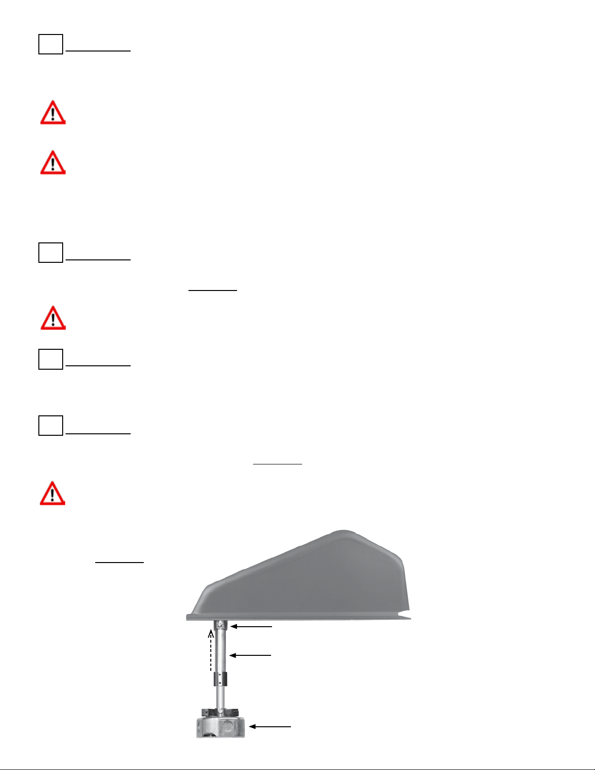
Attach conduit assembly to 3/4” conduit connector mounted below pulley. Once completely inserted,
tighten set screw on conduit connector. See Diagram A.
Never attach or adjust the conduit assembly improperly. is could interfere with the automatic shuto
system and could cause the chandelier to fall, which could cause death, personal injury, and/or property
damage.
ALL200 Ceiling Box
Telescopic Conduit Assembly
3/4” Conduit Connector
Diagram A
STEP 5
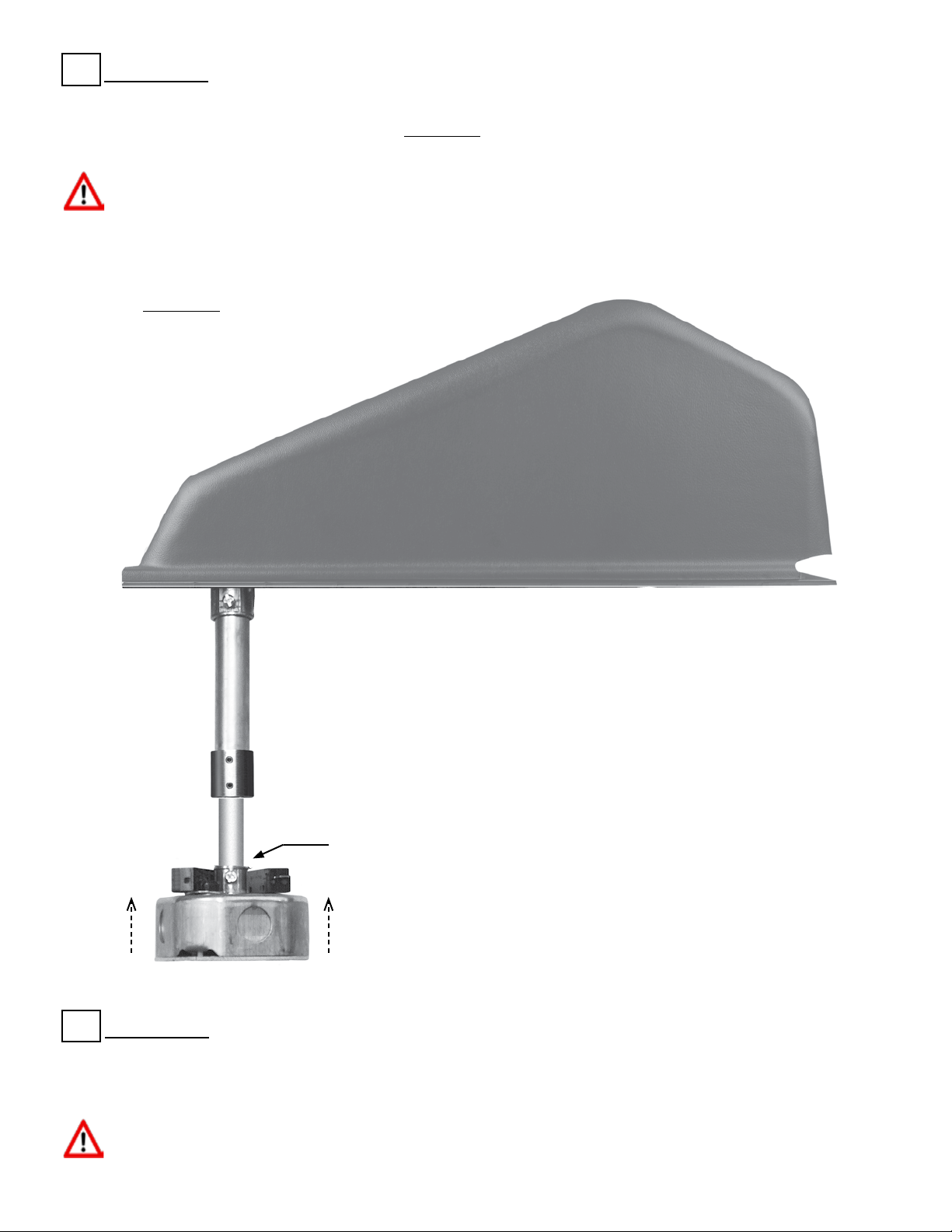
Attach the 1/2” conduit connector on ceiling box to bottom of conduit assembly. Once completely inserted,
tighten set screw on conduit connector. See Diagram B.
Never attach or adjust the conduit assembly improperly. is could interfere with the automatic shuto
system and could cause the chandelier to fall, which could cause death, personal injury, and/or property
damage.
1/2” Conduit Connector
STEP 6
Tighten temporary ve pound weight to xure coupler on bottom contact plate. Make sure jam nut on
weight is tight.
Never install or operate an ALL200 before securing the temporary ve pound weight to the xture
coupler. is could cause the temporary weight to fall, which could cause death, personal injury, and/or
property damage.
Diagram B
STEP 7
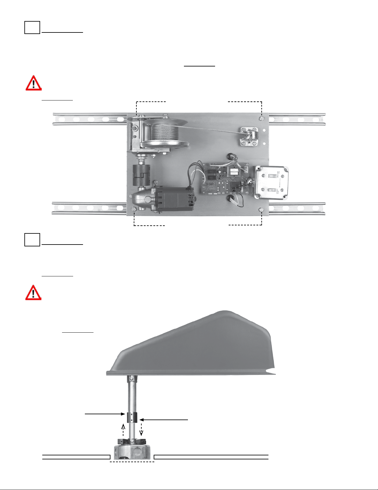
Position ALL200 where ceiling box will be centered in ceiling hole. Weight and bottom contact plate
assembly should hang down through ceiling hole. Adjustments can be made loosening 3/8” channel strut
bolts that hold ALL200 to channel struts. Retighten channel strut bolts after adjustments are made.
Conrm channel strut nuts are seated properly. See Diagram C.
Never adjust the channel struts improperly. is could cause the chandelier to fall, which could cause
death, personal injury, and/or property damage.
Conduit Coupler
Bottom Set Screw
3/32” Allen Wrench
STEP 8
Adjust ceiling box elevation up or down to be ush with sheetrock. Use 3/32” Allen wrench on conduit
coupler to loosen bottom set screw. Conduit assembly is telescopic. e ceiling box should not touch inside
of ceiling hole. Retighten bottom set screw on conduit coupler and conrm top set screw is tight. See
Diagram D.
Never attach or adjust the conduit assembly improperly. is could interfere with the automatic shuto
system and could cause the chandelier to fall, which could cause death, personal injury, and/or property
damage.
Diagram C
3/8” Channel Strut
Adjustment Bolts
3/8” Channel Strut
Adjustment Bolts
Diagram D
4 1/2” Hole
Conduit Coupler
Top Set Screw
3/32” Allen
Wrench
Sheetrock
Sheetrock
 Loading...