

Akura ABLDVD2626W-HDID User's Manual

Model : ABLDVD2626W-HDID
26" Digital LCD TV
with DVD DVBt "Freeview" HDMI
USER'S MANUAL
Customer Helpline: 01422 26 33 13
Website: www.ekey.co.uk

CONTENTS
1
2
3
SAFETY
INFORMATION
SAFETY
PRECAUTIONS
ACCESSORIES
FRONT CONTROLS
4
AND REAR
CONNECTIONS
TV INSTALLATION
5
CONNECTIONS
MAINS LEAD onnectionc
ANTENNA connection
HDMI onnectionc
PC connection
S-VIDEO connection
Y,Pb,Pr onnectionc
SCART onnectionc
AV Connection
CAM (Conditional Access Module)
SERVICE PORT
3
4
5
6
7
7
8
8
9
9
10
10
11
35
REMOTE CONTROL
6
7
MENU
OPERATION
REMOTE CONTROL INSTRUCTIONS in TV mode
R in DTV modeEMOTE CONTROL INSTRUCTIONS
R in TEXT modeEMOTE CONTROL INSTRUCTIONS
REMOTE CONTROL INSTRUCTIONS in DVD mode
REMOTE CONTROL SETUP
TUNING MENU
AUTO TUNING
DTV MANUAL TUNING
ATV MANUAL TUNING
PROGRAM EDIT
PICTURE MENU
SOUND MENU
TIME MENU
OPTION MENU
LOCK MENU
EPG MENU
Fast CHANNEL List
INPUT SOURCE
12
13
14
15
16
17
17
18
18
19
20
21
22
23
24
24
25
25
1

Basic operation
Digital audio/jpeg playback
Function settings
8
DVD
OPERATION
System setup
Screen saver
Password
Rating
Language setup
Audio setup
Audio compression setup
26
26
27
27
28
28
29
30
31
32
TROUBLESHOOTING
9
10
11
12
13
AND ADVICE
DISC CARE
Information
Wall Mounting
SPECIFICATIONS
Useful
33
34
35
35
36
2
1 : Safety Information
Thank you for purchasing this state of the art TV and DVD. Please carefully read this manual before
installing and using the tv. Keep this manual handy for future reference. If the tv is damaged in
transit do not attempt to use it, but contact the supplier immediately.
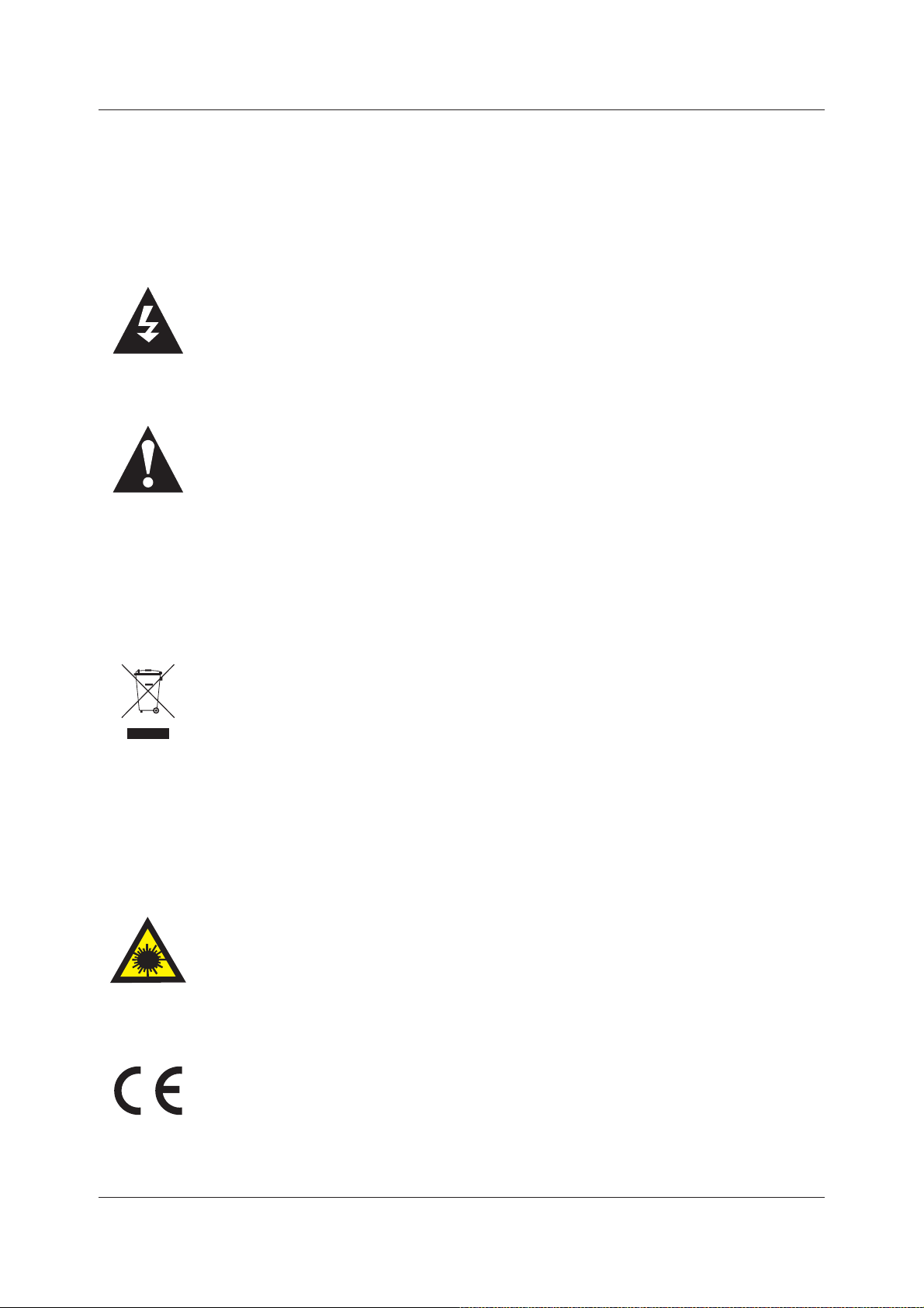
The lightning flash with arrowhead symbol, within an equilateral triangle, is intended
to alert the user to the presence of un-insulated “dangerous voltage” within the
products enclosure that may be of sufficient magnitude to constitute a risk of electric
shock to the persons.
The exclamation point within an equilateral triangle is intend to alert the user to the
presence of important operating and maintenance (servicing) instructions in the
literature accompanying the appliance.
Correct disposal of this Product(Waste Electrical & Electronic Equipment ( WEEE)
The crossed out “Wheelie bin” is intended to show that this appliance must not be
placed with ordinary household waste at the end of its useful life. To prevent possible
harm to the environment or human health from uncontrolled waste disposal, please
keep separate from other household waste and recycle it responsibly to promote
the sustainable reuse of material resources.
Household users should contact either the retailer where you purchased the product,
or their local government office for details of where and how you can take this item
for environmentally safe re-cycling.
Business users should contact their supplier and check the terms and conditions
of the purchase contract. This product must not be mixed with other commercial
wastes for disposal.
This unit is a “CLASS 1” laser product. This product uses a visible laser beam which
could cause hazardous radiation exposure. Ensure the recorder is operated as
instructed. Do not remove any covers or look into the DVD drawer opening whilst
power is applied. Do NOT modify or adjust any controls that may affect laser emissions.
Should the appliance become faulty consult a qualified technician.
This appliance complies with European Safety and Electrical directives
3
2: Safety Precautions
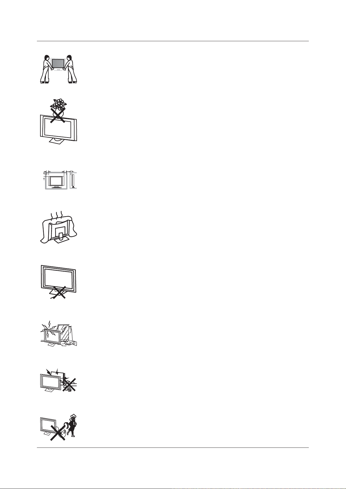
Unpacking and Handling. Open the carton carefully and remove the top
polyfoam packing. Carefully lift the Tv (2 persons) and place onto a firm
stable surface. Lift off the Poly bag and retain all packaging for future use.
Keep all packaging away from small children and animals.
Placing Tv. The tv should be placed on a firm table or shelf. Do not place
in a cabinet unless there is sufficient spacing for air flow and access for the
DVD player opening.
Minimumdistances
10cm
20cm
10cm 5cm
Connections. When connecting the tv to external sources and the mains
supply, do not place wires that can be tripped over. Do not place heavy
objects, bend or trap the mains lead.
Top of Tv. Do not place objects such as vases, candles or other objects
which may spill into the Tv.
Ventilation and Heat Sources. Do not place material over the ventilation
slots, this will cause the tv to overheat and fail. Do not place the Tv in direct
sunlight or near heat sources such as radiators or fires.
Moisture. Do not place the Tv in wet or damp conditions, such as steamy
kitchens, basements or other damp places. Do not allow water or other fluids
to enter the Tv. Do not touch the Mains plug with wet hands. Should moisture
enter the Tv , disconnect from the supply and call the customer help line.
Cleaning. Disconnect the Tv from the mains supply. Use a soft dry cloth,
for stubborn stains use a soft moist cloth with a dilute mild detergent.. Do
NOT use petrol based fluids
Leaving your Tv. Do not leave your tv operating whilst un attended. It is
wise to switch off at the Power switch. To conserve power do not leave the
tv in standby for long periods “overnight”. When leaving the tv for long periods
“holidays” and when local thunderstorms occur, discon- nect the aerial “if
external” and mains supply.
4

3 : Accessories
POWER MUTE SOURCE
PMODE SMODE AUDIO SLEEP
I/II
1234
5678
10
+10
LIST
9
0
TV MENU
EXIT
TEXT
GOTO
OK
ENTER
PROGRAM
DISPLAY
INFO
LCDTVSET
Model : ABLDVD2626W-HDID
26" Digital LCD TV
with DVD DVBt "Freeview" HDMI
V-
DVD SETUP
SUBTITLE HOLD
MIX INDEX
D.MENU
TV/RADIO
P+
V
+
P-
ANGLE REPEAT
A-B
SIZE
REVEAL
D.DIS
SUBPAGE
FAV
ZOOM
EPG
Remote Control
USER'S MANUAL
Customer Helpline:01422 26 3313
Website: www.ekey.co.uk
User's Manual
Power Cord
Should any of the items be missing or damaged. Please contact your point of purchase.
5
4 : Front Controls and Rear Connections
V+
V-
P+
P-
MENU
SOURCE
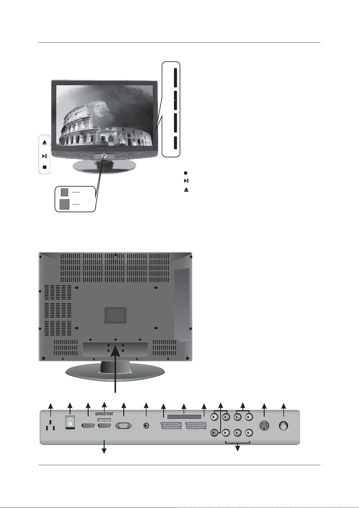
1. Power. Switches Tv from Standby to operate
and back to standby.
2. V+/V- Increases and Decreases volume level.
.
3. P+/P-. Selects TV channels up and down.
4. Menu. Selects operational menu’s
5. Source. Selects input source
6 Led Indicator. Displays status of Tv. Red in
.
.
.
standby, Green in operation.
POWER
6
7. IR. Infra red receiving window for Remote
Control
8. ON/OFF Mains switch
.
.
STOP in DVD mode
.
PLAY/PAUSE in DVD mode
EJECT in DVD Mode
.
.
7
15
AC POWER
SWITCH
1
HDMI2
HDMI1
3
PC IN
4
PC
AUDIO
5
1413
CI PORT
SCART1 SCART2
1. HDMI 2 input
2. HDMI 1 input
3. PC Input (VGA) input
4. PC Audio input
5. SCART 1
6. SCART 2
7. Y Pb Pr Component input
8. Audio L/R. Y Pb Pr input
9. AV composite/ L/R Audio
10. S-VIDEO input
11. Tuner RF input
12. Mains supply Input
13. Engineering connection
14. CI Slot (CAM Module)
15. Mains Switch
67
Pb
YPrVIDEO
L
L
10
S-VIDEO
1112
RF INAC IN
8
R
R
9
6
5 : Tv Installation Connections
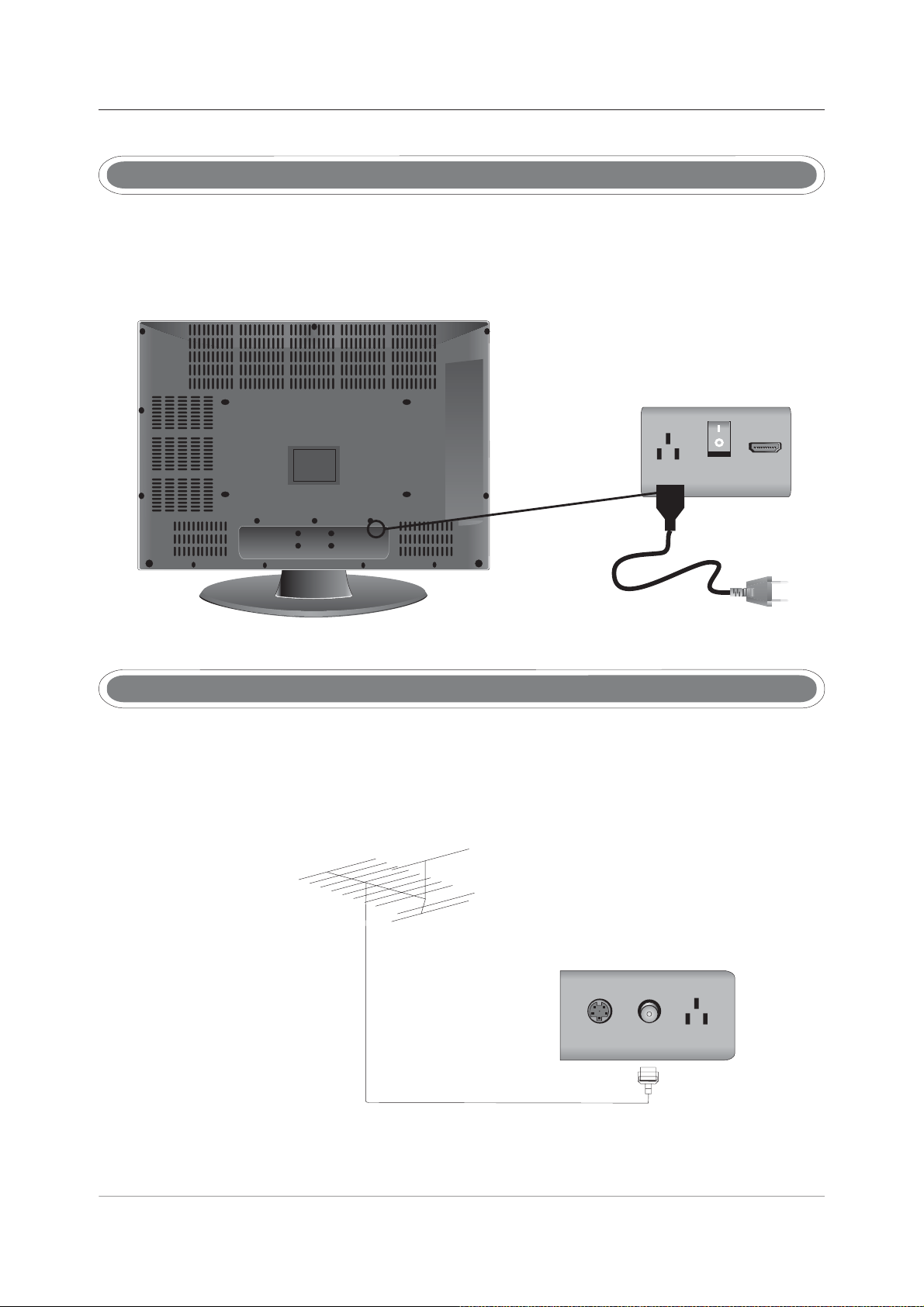
Mains lead Connection
Connect the Mains lead as shown.
Press the POWER switch to turn the Tv on. The LED will change from Red to Green.
AC IN
AC POWER
SWITCH
HDMI2
ConnectionAntennas
Insert the Tv Antenna plug into the rear of the Tv as shown. For best results an external (outdoor)
antenna is recommended. DVBt (digital) signals need to be of high quality. If your antenna system
is old it may need replacing.
UHF ANTENNA
7
S-VIDEO
RF IN
AC IN
75 OHM
ANTENNA
PLUG
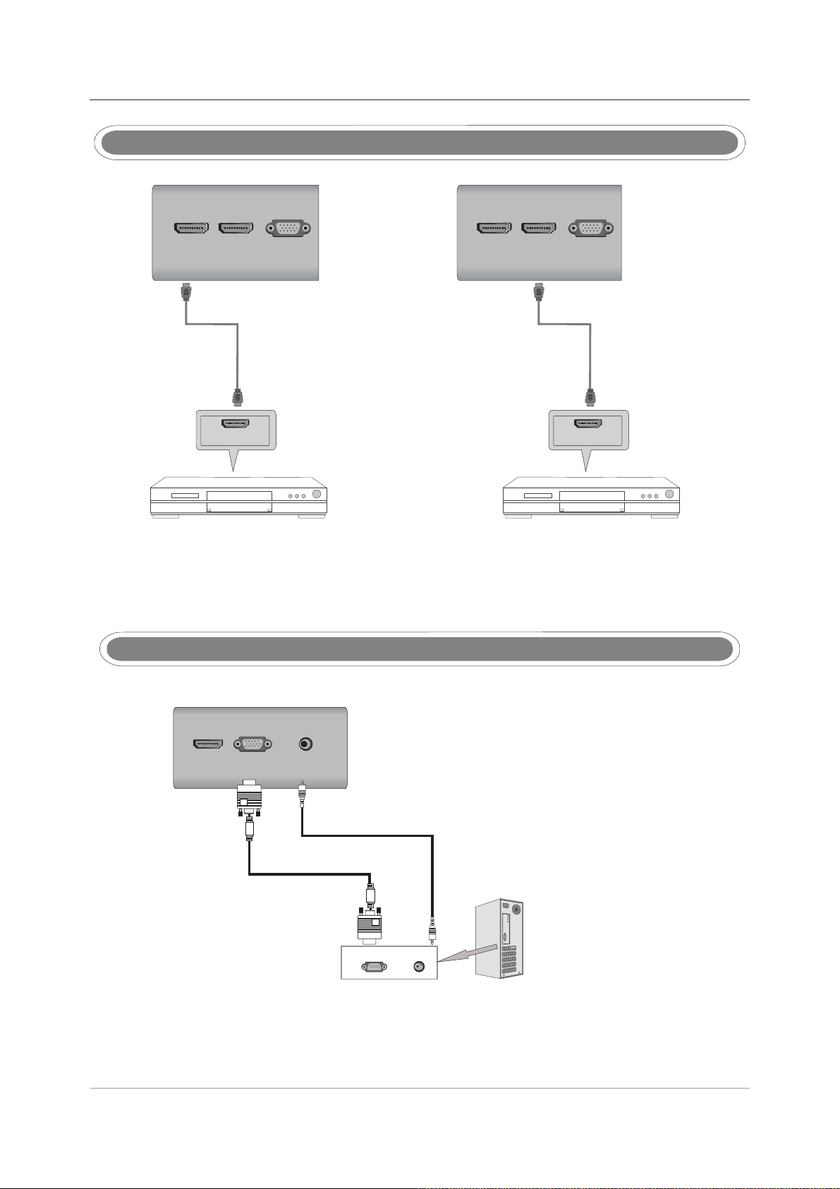
HDMI Connection
HDMI2 PC INHDMI1
TV Back
HDMI Cable
HDMI OUT
DVDorVCR Back
DVD orVCR
HDMI2 PC INHDMI1
TV Back
HDMI Cable
HDMI OUT
DVDorVCR Back
DVD orVCR
Connect HDMI output from DVD/VCR or X box or similar to the tv and use the “SOURCE” button to
select HDMI 1 or 2. (Leads not supplied)
PC Connection
PC INHDMI1
PC
AUDIO
TV Back
Stereo Audio Cable
PC IN
AUDIORGB-PC OUTPUTRGB-PC OUTPUT
Connect the VGA output from your PC to the VGA input of the tv. If you are using sound, connect
the PC audio to the tv PC audio input (leads not supplied). Use the SOURCE button to select VGA
8

S-VIDEO Connection
Pb
VIDEO
Audio Cable
S-VIDEO Cable
AUDIO
DVD or VCR Back
L
R
S-VIDEO
L
R
RF IN
TV Back
DVDorVCR
Connect the S_VIDEO output of the DVD, VCR or other item, to the S-VIDEO input on the tv. The
picture quality will be improved compared with SCART or AV input. Connect the Audio output of the
DVD, VCR or other item to the Audio input sockets on the tv using a stereo RCA cable (not supplied).
Select S-VIDEO using the SOURCE button on the remote control or tv. Do not connect more than
one video cable to each item as this may cause interference on the picture.
YPbPr Connection
Pb
SCART2
YPrVIDEO
RCA Video Cable
RCA Audio Cable
Pr Pb Y
DVD or VCR Back
LR
DVDorVCR
Connect the Y PbPr output of the DVD, VCR or other item to the Y PbPr input on the tv. (lead not
supplied). The picture quality will be improved, compared with SCART or AV input. Connect the
Audio output of the DVD,VCR or other item to the Audio input sockets of the tv, using a stereo RCA
cable , (not supplied). Select HD using the SOURCE button on the remote control or tv. Do not
connect more than one video cable to each item as this may cause interference on the picture.
9
L
R
S-VIDEO
L
R
TV Back
PC
AUDIO
SCART1 SCART2
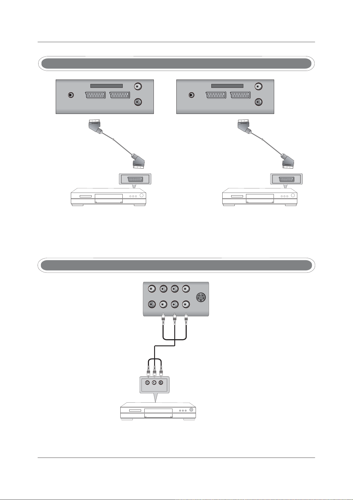
ConnectionSCART
CI PORTCI PORT
Pr
PC
Y
AUDIO
SCART1 SCART2
Pr
Y
Scart cable
DVD or VCR Back
DVDorVCR
TV Back
DVD or VCR Back
TV Back
Scart cable
DVDorVCR
Connect the SCART connector to the external video item and the SCART connector on the tv.
(lead not supplied). The SCART lead operates as an Input/Output connection. If the tv does not
select the SCART input automatically, select SCART using the SOURCE button on the remote
controlortv.
AV Connection
Pb
YPrVIDEO
L
R
S-VIDEO
L
R
TV BackTV Back
1
Video CableVideo Cable
VLRV LR
DVDorVCRBackDVD or VCR Back
DVD or VCRDVD or VCR
Connect the Video and Audio output connections of the external item to the Video and Audio inputs
on the tv. Match the colours correctly, Video is Yellow, Audio Left is White, Audio Right is Red.
Select AV as the Source using the SOURCE button on the remote control or tv.
10
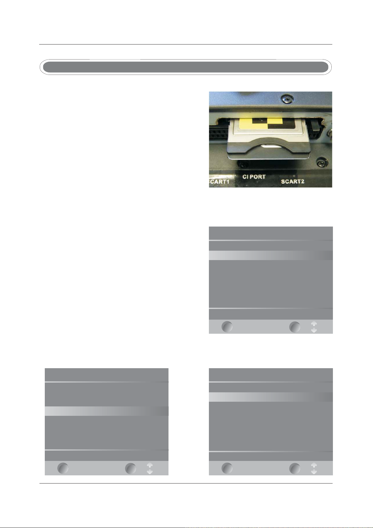
CAM (Conditional Access Module)
Using a CAM (Conditional Access Module) (CI Slot).
This feature allows the user to access digital terrestrial
“pay per view” channels. To use the facility a
conditional access module (CAM) and viewing card
need to be obtained by subscribing to a pay channel
company.
To insert the module, Ensure the TV is fully
disconnected from the power source.
Insert the CAM into the CI slot ensuring that the label
is facing towards the “wall” see Fig 1. A positive stop
should be felt if correctly fitted. DO NOT force the
module.
To release the CAM hold the two sides with fingers and pull gently.
Re connect the TV to the power and switch on. Select
DTV.
Insert your “Pay per view” card, “do NOT touch the
gold contacts”.
Main menu
Press the MENU button and enter the TUNING menu.
Select CI Information and press ENTER. (Fig 2)
Select Module Information and press ENTER (Fig 3)
To see the card information, select Card Information
and press ENTER.
Module information
Smart card information
Language
Software Download
If everything is working satisfactorily you should see
the information similar to Fig 4.
Exit the menu’s by pressing MENU or let the TV time
Press OK to select, or Exit to quit.
out automatically and you are ready to view “pay per
view”.
EXIT
To obtain the CAM and pay per view card, these may
be purchased from good high street stores.
Fig1
Fig2
OK
Smart card information
Serial number: 562443907
TopUp TV 1 16/03/2008 (d/m/y)
ADMIN 16/03/2008 (d/m/y)
Press OK Exit to quit.
EXIT
OK
11
Fig3Fig4
Module information
Module information
Serial number: 11410734415011
SAP number: 904244R10
Manufacturer: SCM Microsystems
SW version: Rop Up TV 1.03.002
FW version: 1.04.03
Mediaguard version: Ver 01.03 R 04(16/11/04)
Download ID: 2
Press Okor Exit to quit.
EXIT
OK
 Loading...