

Page 1

Page 2
Page 3

Dear Aksa Generating Set Users;
First of all, we would like to thank you for your choice of Aksa Generating Set.
It is solid, safe and reliable machine, built according to the latest technology.
This operating and maintenance manual is designed and developed to make you familiar
with the generating system.
Please read the following instructions carefully before starting to use your machine.
This manual gives general information about mounting, operation and maintenance
of the generating set. Tables and diagrams are also available outlining your generating set.
Never operate, maintain or repair your generating set without taking general safety precautions.
Aksa Jeneratör does not assume responsibility for possible errors.
Aksa Jeneratör reserves to make changes without prior notice.
Page 4

1. INTRODUCTION 3
2. GENERAL SAFETY PRECAUTIONS 4
2.1 General 4
2.2 Installation Handling and Towing 4
2.3. Fire and Explosion 4
2.4. Mechanical 5
2.5. Chemical 5
2.6. Noise 5
2.7. Electrical 5
2.8 FIRST AID FOR ELECTRIC SHOCK 6
3. GENERAL DESCRIPTION 7
3.1. Generating Set Description and Identification 7
3.2 Generating Set Main Parts 8
3.3 Diesel engine 9
3.4. Engine Electrical System 9
3.5. Cooling System 9
3.6. Synchronous Alternator 9
3.7. Coupling 9
3.8. Fuel Tank and Base Frame 9
3.9. Vibration Isolation 9
3.10. Silencer and Exhaust System 9
3.11. Control System 10
4. INSTALLATION HANDLING AND STORAGE 10
4.1. General 10
4.2. Canopies 10
4.3. Moving the Generating Set 10
4.4. Location 10
4.5. Base and Foundation 11
4.6. Room design guidance notes 12
5. FUEL SYSTEM 16
5.1. General 16
5.2.
Fuel oil Recommendation 16
5.3. Base Fuel Tank 16
5.4. Bulk Storage Tanks 17
5.5. Without Intermediate Fuel Tank 17
5.6. With Intermediate Fuel Tank 17
5.7. Daily Service Fuel Tank 17
5.8. Determining Pipe Sizes 18
5.9. Fuel Return Lines 18
6. WATER TREATMENT 20
6.1. General 20
6.2. Engine coolant 20
6.3. Engine Warming 20
1
Page 5
2
Page 6
1. INTRODUCTION
This operating and maintenance manual is prepared to assist
the operator in operation and maintenance of the generating
set. Observing the advices and rules in this manual will ensure
that the generating set operates in maximum performance
and efficiency for a long time.
- Care should be taken to perform more frequent maintenance
in dirty and dusty environments in order to keep the generating
set in good working condition.
- Necessary adjustment and repairs should be made only by
authorized and qualified persons.
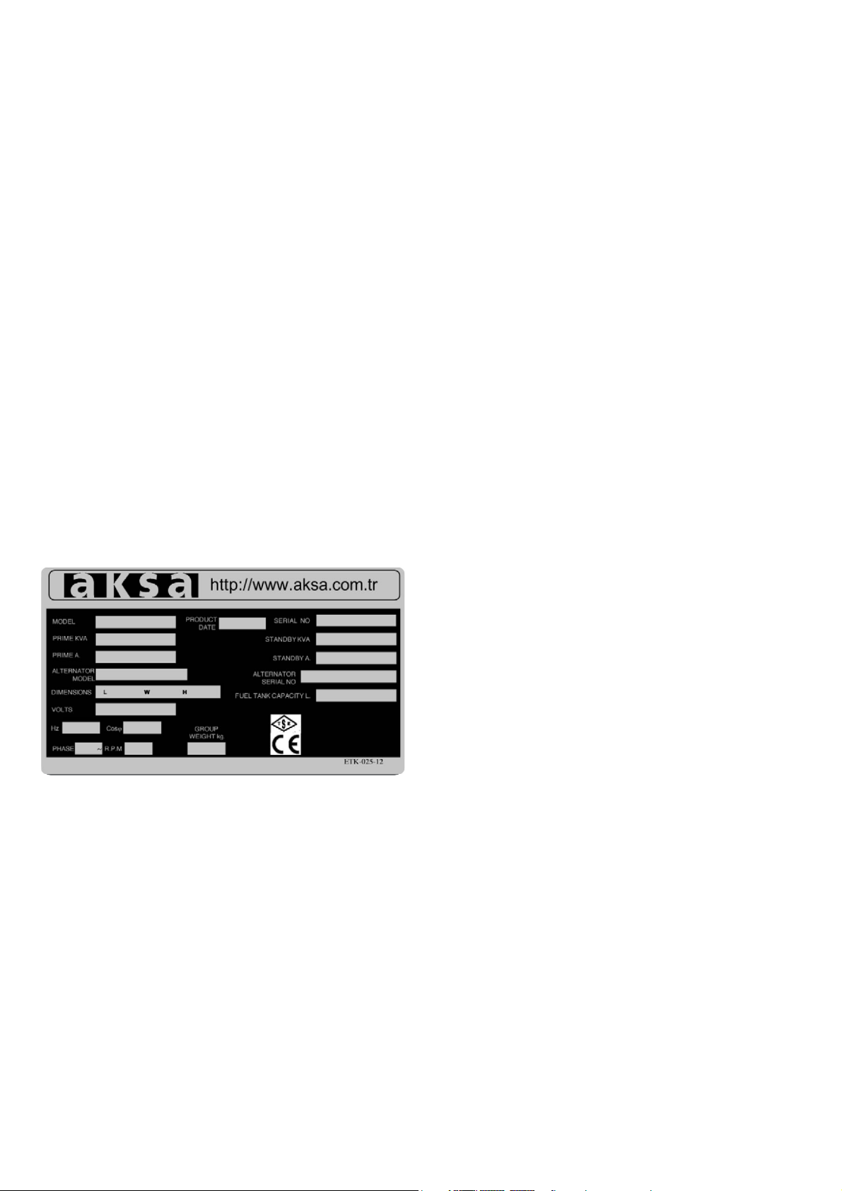
- Each generating set has a model and a serial number indicated
on a label on the base frame. This plate also indicates the
manufacturing date, voltage, current, power in kVA, frequency,
power factor and weight of the generating set. These datas
are necessary in spare part orders, for warranty validity and
Only people that have the right skills should be allowed to
operate, adjust, perform maintenance or repair on Aksa Power
Generation equipment. It is the responsibility of management
to appoint operators with the appropriate training and skill
for each category of job.
Skill level 1 : Operator
An operator is trained in all aspects of operating the unit with
the push- buttons, and trained to know the safety aspects.
Skill level 2 : Mechanical technician
A mechanical technician is trained to operate the unit the
same as the operator. In addition, the mechanical technician
is also trained to perform maintenance and repair, as describe
in the instruction manual, and is allowed to change settings of
the control and safety system. A mechanical technician does
not work on live electrical components.
for service calls.
The generating set is designed to be safe when used in correct
manner. However responsibility for safety rests with the
personnel who install, use and maintain the set. If the following
safety precautions are followed, the possibility of accidents will
be minimized. Before performing any procedure or operating
technique, it is up to the user to ensure that it is safe.
The generating set should only be operated by personnel
who are authorized and trained.
Skill level 3 : Electrical technician
An electrical technician and has the same qualifications as both
the operator and the mechanical technician. In addition, the
electrical technician may carry out electrical repairs within the
various enclosures of the unit. This includes work on live
electrical components.
Skill level 4: Specialist from the manufacturer
This is skilled specialist sent by the manufacturer or its agent
to perform complex repairs or modifications to the equipment.
In general it is recommended that not more than two people
operate the unit, more operators could lead to un safe
operating conditions. Take necessary steps to keep unauthorized
person away from the unit and eliminate all possible source
of danger at the unit.
The manufacturer does not accept any liability for any damage
arising from the use of non-original parts and for modifications,
additions or conversions made without the manufacturer's
approval in writing.
3
Page 7
2. GENERAL SAFETY PRECAUTIONS
WARNING
2.1. GENERAL
1 The owner is responsible for maintaining the unit in a safe
operating condition. Unit parts and accessories must be
replaced if missing or unsuitable for safe operation.
2 Operate the unit only for the intended purpose and within
its rated limits (pressure, temperature, speeds, etc.).
3 Gen-set and equipment shall be kept clean, i.e. as free as
possible from oil, dust or other deposits.
4 To prevent an increase in working temperature, inspect
and clean heat transfer surfaces (cooler fins, intercoolers,
water jackets, etc.) regularly.
5 Take precautions against fire. Handle fuel, oil and anti-freeze
with care because they are inflammable substances. Do
not smoke or approach with naked flame when handling
such substances. Keep a fire-extinguisher in the vicinity.
WARNING
! Make electrical connections in compliance with relevant
Electrical Codes, Standards or other requirements. This includes
requirements for grounding and ground/earth faults.
! For stationary generating sets with remote fuel storage
systems, make sure such systems are installed in compliance
with relevant Codes, Standards or other requirements.
! Engine exhaust emissions are hazardous to personnel. The
engine exhaust for all indoor generating sets must be piped
outdoors via leak-free piping in compliance with relevant
Codes, Standards and other requirements. Ensure that hot
exhaust silencers and piping are clear of combustible material
and are guarded for personnel protection per safety
requirements. Ensure that fumes from the exhaust outlet will
not be a hazard.
! Never lift the generating set by attaching
to the engine or alternator lifting lugs,
! Read and understand all safety precautions and warnings
before operating or performing maintenance
on the generating set.
! Failure to follow the instructions, procedures, and safety
precautions in this manual may increase the possibility of
accidents and injuries.
! Do not attempt to operate the generating set with a known
unsafe condition.
! If the generating set is unsafe, put danger notices and
disconnect the battery negative (-) lead so that it
cannot be started until the condition is corrected.
! Disconnect the battery negative (-) lead prior to attempting
any repairs or cleaning inside the enclosure.
! Install and operate this generating set only in full compliance
with relevant National, Local or Federal Codes, Standards
or other requirements.
instead use the lifting points on the base
frame or canopy.
! Ensure that the lifting rigging and
supporting structure is in good condition and has a capacity
suitable for the load.
! Keep all personnel away from the generating set when it
is suspended.
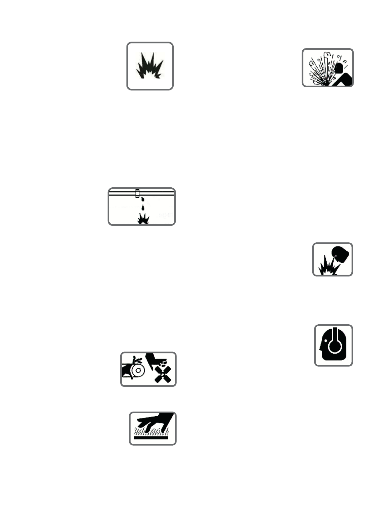
2.3. FIRE AND EXPLOSION
Fuel and fumes associated with generating sets can be flammable
and potentially explosive. Proper care in handling these materials
can dramatically limit the risk of fire or explosion. However,
safety dictates that fully charged BC and ABC fire extinguishers
are kept on hand.
Personnel must know how to operate them.
WARNING
2.2. INSTALLATION, HANDLING AND TOWING
Chapter 4 and 12 of this manual covers procedures for
installation, handling and towing of generating sets. That chapter
should be read before installing, moving and lifting the generating
set or towing a mobile set. The following safety precautions
should be noted:
! Ensure that the generating set room is properly ventilated.
! Keep the room, the floor and the generating set clean.
When spills of fuel, oil, battery electrolyte or coolant occur,
they should be cleaned up immediately.
! Never store flammable liquids near the engine.
! Do not smoke or allow sparks, flames or other sources of
ignition around fuel or batteries.
Fuel vapors are explosive. Hydrogen gas generated by
charging batteries is also explosive.
4
Page 8
! Never store flammable liquids near the engine.
! Wear protective clothing including gloves and hat when
! Do not smoke or allow sparks,
flames or other sources of ignition
around fuel or batteries.
Fuel vapors are explosive.
Hydrogen gas generated by charging
batteries is also explosive.
! Turn off or disconnect the power to the battery charger
before making or breaking connections with the battery.
! To avoiding arcing keep grounded conductive objects
(such as tools) a way from exposed live electrical parts
(such as terminals). Sparks and arcing might ignite fuel or
vapors.
! Avoid refilling the fuel tank while the engine is running.
! Do not attempt to operate
the generating set with any
known leaks in the
fuel system.
working around the generating set.
! Do not remove the radiator filler
cap until the coolant has cooled.
Then loosen the cap slowly to relieve
any excess pressure before removing
the cap completely.
2.5. CHEMICAL
Fuels, oils, coolants, lubricants and battery electrolyte used in
this generating set are typical of the industry. However, they
can be hazardous to personnel if not treated properly.
WARNING
! Do not swallow or allow skin contact with fuel, oil, coolant,
lubricants or battery electrolyte. If swallowed, seek medical
treatment immediately. Do not induce vomiting if fuel is
swallowed. For skin contact, wash with soap and water.
! Do not wear clothing that has been contaminated by fuel
or lube oil.
2.4. MECHANICAL
The generating set is designed with guards for protection from
moving parts. Care must still be taken to protect personnel
and equipment from other mechanical hazards when working
around the generating set.
WARNING
! Do not attempt to operate the generating set with the safety
guards removed. While the generating set is running do not
attempt to reach under or around the guards to do maintenance
or for any other reason.
! Keep hands, arms, long hair, loose
clothing and jewelers away from
pulleys, belts and other moving parts.
Attention: Some moving parts cannot be seen clearly when
the set is running.
! Wear an acid resistant apron and
face shield or goggles when servicing
the battery. If electrolyte is spilled
on skin or clothing, flush immediately
with large quantities of water.
2.6. NOISE
Generating sets that are not equipped with sound attenuating
enclosures can produce noise levels
in excess of 105 dB(A). Prolonged
exposure to noise levels above 85 dB(A) is
hazardous to hearing.
WARNING
Ear protection must be worn when operating or working
around an operating generating set.
! If equipped keep access doors on
enclosures closed and locked when
not required to be open.
! Avoid contact with hot oil, hot coolant, hot exhaust gases,
hot surfaces and sharp edges and corners.
5
Page 9
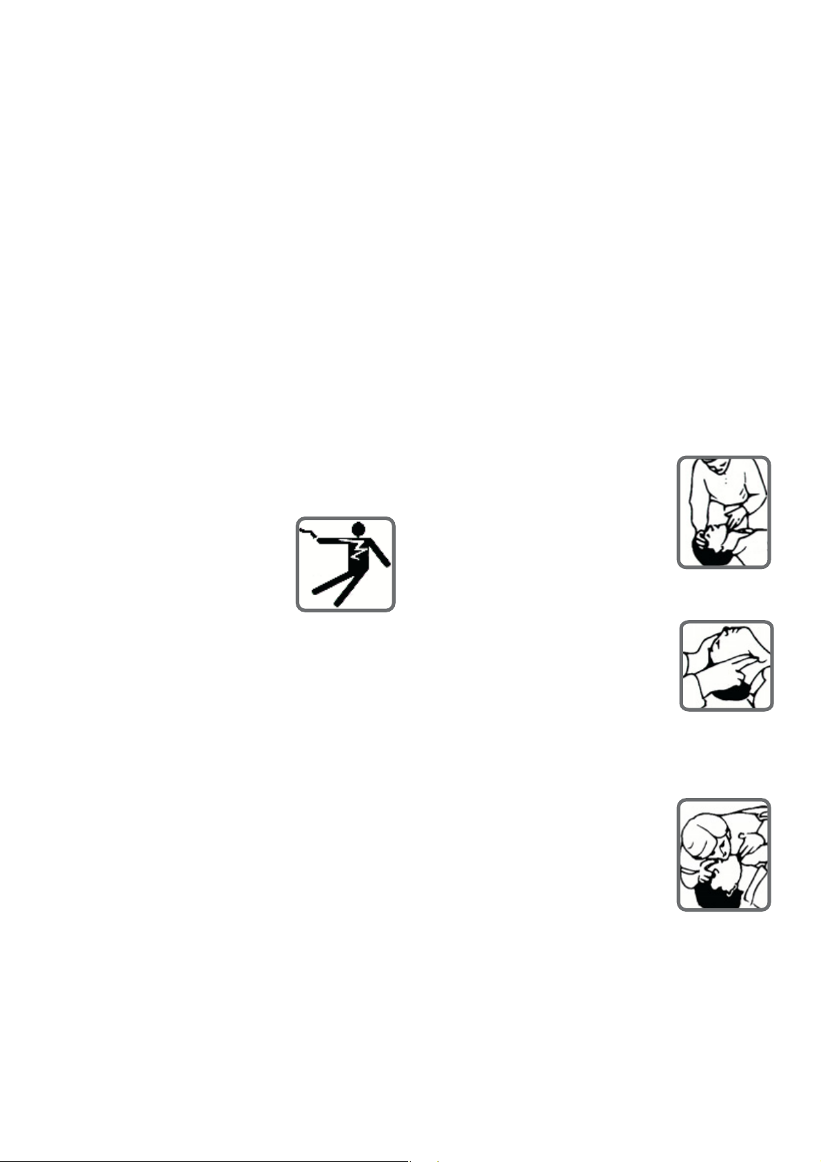
2.7. ELECTRICAL
2.8 FIRST AID FOR ELECTRIC SHOCK
Safe and efficient operation of electrical equipment can be
achieved only if the equipments is correctly installed, operated
and maintained.
WARNING
!
The generating set must be connected to the load
only by trained and qualified electricians who are
authorized to do so, and in compliance with relevant
Electrical Codes, Standards and other regulations.
!
Ensure that the generating set, including a mobile set
is effectively grounded/earthed in accordance with all
relevant regulations prior operation.
!
The generating set should be shutdown with the
battery negative (-) terminal disconnected prior to
attempting to connect or disconnect load connections.
!
Do not attempt to connect or disconnect load
connections while standing in water or on wet or soggy
WARNING
! Do not touch the victim's skin with bare hands until
the source of electricity has been turned off.
! Switch off power if possible other wise pull the plug
or the cable away from the victim.
! If this is not possible, stand on dry insulating material
and pull the victim clear of the conductor, preferably
using insulated material such as dry wood.
! If victim is breathing, turn the victim clear of the
conductor, preferably using insulated material such as
dry wood.
! If victim is breathing, turn the victim into the recovery
position described below. If victim is unconscious,
perform resuscitation as required;
Open the airway
Tilt the victim’s head back and lift
ground.
!
Do not touch electrically energized
parts of the generating set and/or
interconnecting cables or conductors
with any part of the body or with any
non insulated conductive object.
!
Replace the generating set terminal box cover as
soon as connection or disconnection of the load cables
is complete. Do not operate the generating set without
the cover securely in place.
!
Connect the generating set only to loads and/ or
electrical systems that are compatible with its electrical
characteristics and that are within its rated capacity.
!
Keep all electrical equipment clean and dry. Replace
any wiring where the insulation is cracked, cut, abraded
or otherwise degraded. Replace terminals that are worn,
discolored or corroded. Keep terminals clean and tight.
!
Insulate all connections and disconnected wires.
!
Use only Class BC or Class ABC extinguishers on
electrical fires.
the chin upwards. Remove objects
from the mouth or throat
(including false teeth,
tobacco or chewing gum).
Breathing
Check that the victim is
breathing by looking, listening
and feeling for the breath.
Circulation
Check for pulse in the victim’s neck.
If no breathing but pulse is present
Pinch the victim's nose firmly.
Take a deep breath and seal your
lips around the victim's lips.
Blow slowly into the mouth
watching for the chest to rise.
Let the chest fall completely.
Give breaths at a rate of 10 per minute.
If the victim must be left to get help, give 10 breaths
first and then return quickly and continue.
Check for pulse after every 10 breaths. When
breathing restarts, place the victim into the recovery
position described later in this section.
6
Page 10
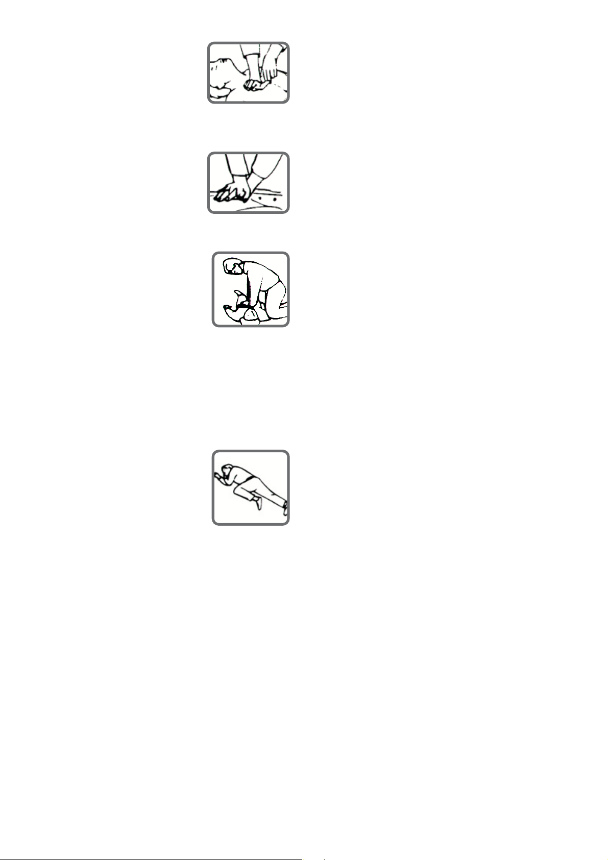
If no breathing and no pulse
Call or telephone for medical help.
Give two breaths and start chest
compression as follows:
Place heel of hand 2 fingers breadth above
ribcage/breastbone junction.
Place other hand on top and
interlock fingers.
3. GENERAL DECRIPTION
3.1. Generating Set Description and Identification
Diesel-electric generating sets are independent units for the
production of electric power; basically, they comprise a constant
voltage synchronous generator driven by an internal combustion, diesel -cycle engine.
The sets are used for two main purposes:
a- Continuous duty sets,
used to produce electric power for countless requirements
(motive power, lighting, heating, etc) in areas where other
Keeping arms straight, press down 4-5 cm at a rate
of 15 times per minute.
Repeat cycle (2 breaths and
15 compressions) until medical
helps takes over.
If condition improves, confirm
pulse and continue with breaths.
Check for pulse after every 10 breaths.
When breathing restarts, place the
victim into the recovery position described below.
3.6. Recovery position
Turn the victim onto the side.
Keep the head tilted with the jaw
forward to maintain the open
airway.
Make sure the victim cannot roll
sources or power are unavailable.
b- Emergency duty sets,
Used during public network failures, when such failures are
liable to cause serious trouble to persons or material or
financial damage (i.e. in hospitals, industrial plants with nonstop operating cycles, etc) or to meet peak energy demands.
According to their application, the sets are further divided
into:
- set for use on land
- set for use at sea
The sets for use on land can be either :
- stationary sets (fixed installation), or
- mobile sets (mobile installation)
forwards or backwards.
Check for breathing and pulse regularly. If either stops,
proceed as above.
WARNING
! Do not give liquids until victim is conscious.
These two types of sets are available in a vast range of versions,
for every operating requirement, the main ones being:
01. hand control generating sets
02. stand-by generating sets
The standard stationary generating set comprises:
- diesel engine
- synchronous generator
- coupling
- metal sub-base with vibration isolators
- starter batteries
- fuel tank within the bed-plate
- instrument panel
- exhaust gas silencer.
7
Page 11
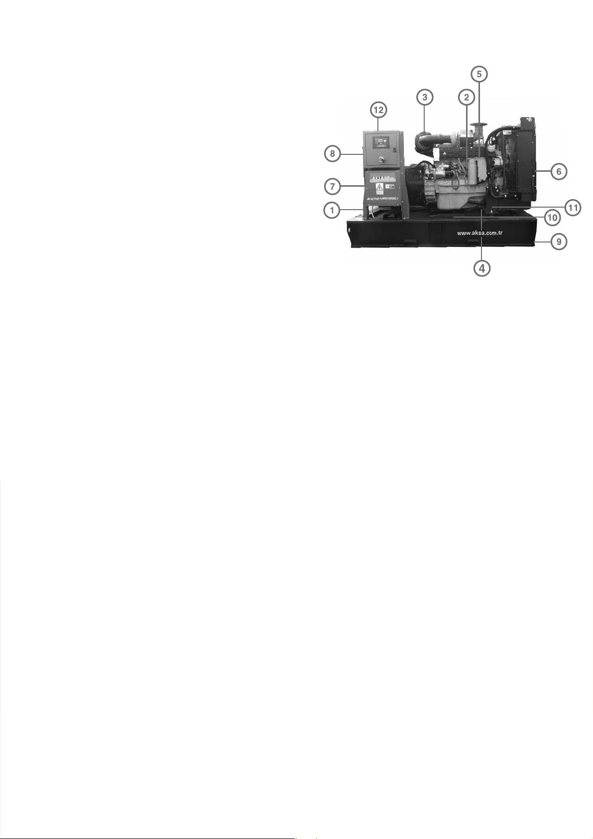
Aksa Generating Set has been designed as a complete package
to provide superior performance and reliability.
Figure 3.1. identifies the major components. This figure is of
a typical generating set. However, every set will be slightly
different due to the size and configuration of the major
components. This section briefly describes the parts of the
generating set. Further information is provided in later sections
of this manual.
Each generating set is provided with a Rating Label (Item 1)
generally fixed to the base frame. This label contains the
information needed to identify the generating set and its
operating characteristics. This information includes the model
number, serial number, output characteristics such as voltage
and frequency, output rating in kVA and kW, product date and
3.2. Generating Set Main Parts
weight.
The model and serial numbers uniquely identify the generating
set and are needed when ordering spare parts or obtaining
service or warranty work for the set.
AC series generating sets are an Alternating Current generator,
built for continuous running at sites where no electricity is
available (some models are excepted) or as stand-by in case
of interruption of the mains.
The generator operates at 230/220 V in line-to-neutral mode
and 400/440 V in line-to-line mode. The AC series generating
set is driven by a water-cooled diesel engine.
Figure 3.1. Typical generating set configuration
No Description
1. Aksa generating set rating label
2. Diesel engine
3. Air filter
4. Battery
5. Battery charging alternator
6. Radiator
7. Alternator
8. Terminal box
9. Base frame
10. Fuel tank (inside the base frame)
11. Vibration isolators
12. Control Panel
8
Page 12

3.3. Diesel Engine
The diesel engine powering the generating set (Item 2)
has been chosen for its reliability and the fact that it has
been specifically designed for powering generating sets.
The engine is of the heavy duty industrial type with 4
stroke compression ignition and is fitted with all
accessories to provide a reliable power supply. These
accessories include, among others, a cartridge type dry
air filter (item 3) and a mechanical or an electronic
engine speed governor. The engine cylinder block is cast
in one piece cast iron, vertical cylinders inline overhead
valves and camshaft in block or V- type, according to the
type.
The cylinder heat is made of special cast iron. The
thermally loaded flame plate is efficiently water cooled.
The crankshaft is forged in one piece in a high tensile
steel.
Lubrication: forced lubrication via gear pump, special
paper cartridge -type filters, lubricant cooling via heat
exchanger on most versions.
The output electrical power is normally produced by
a screen protected and drip-proof, self-exciting, self
regulating, brushless alternator. (Item 7) Fine tuned to
the output of this generating set. Mounted on top of
the alternator is a sheet steel terminal box (item 8)
3.7. Coupling
Engine and alternator are firmly joined by a coupling
cone that guarantees the proper assembly coaxiality
Mono-support machines are also used a special flexible
disk is used in place of a flexible coupling.
3.8. Fuel tank and Base frame
The engine and alternator are coupled together and
mounted on a heavy duty steel base-frame (Item 9).
This base frame includes a fuel tank (Item 10) with
capacity of approximately 8 hours operation under
variable loads. The tank is complete with filling cap and
fuel level gauge and is connected by flexible joints to
the intake piping and to the overflow piping containing
fuel from the injector drain. High power gen-set's fuel
3.4. Engine Electrical System
The engine electrical system is 12 volt or 24 volts DC,
negative ground/earth. This system includes an electric
engine starter, a battery (item 4) and a battery charging
alternator (item 5). For 12 volts electrical system one
battery is given. For 24 volt system two lead-acid batteries
are given. Other types of batteries may be fitted if they
were specified.
3.5. Cooling System
The engine cooling system is water cooled. The water
cooled system is comprised of a radiator (item 6) a
pusher fan and thermostat. The alternator has its own
internal fan to cool the alternator components.
3.6. Synchronous Alternator
Horizontal axle alternator (synchronous three phase),
on rolling bearings, self-ventilated within the room with
low-loss silicon-sheet stator bundle, electrolytic copper
winding with class H insulation.
tank is separate from gen-set.
3.9. Vibration Isolation
The generating set is fitted with vibration isolators (Item
11) which are designed to reduce engine vibration being
transmitted to the foundation on which the generating
set is mounted. These isolators are fitted between the
engine /alternator feet and the base frame.
3.10. Silencer and Exhaust system
Exhaust gases from the turbocharger are discharged
toward atmosphere through a silencer. These should be
vented as high as possible, and must be prevented from
re-entering the engine via the charge air intake, or
polluting the radiator fins.
It is important to note that the turbocharger nozzles
must be always free of loads. Stainless steel exhaust
compensator is delivered with generator set.
Exhaust lines of different engines shall not be mixed in
a common stack, but routed separately in individual
ducts, enclosed in a chimney.
9
Page 13
Suitable material is carbon steel sheet, and recommended
Using for a forklift, the generating set can be lifted or
calculation temperature is 525oC. Rain and condensate
permanent draining shall be provided to prevent water
entering the silencer and the engine.
An exhaust silencer is provided loose for installation
with the generating set. The silencer and exhaust system
reduce the noise emission from the engine and can
direct exhaust system reduce the noise emission from
engine and can direct exhaust gases to safe outlets.
The exhaust silencer is made of a carbon steel receiver
containing sound attenuator and wave de-phasing system
made of perforated steel sheet and heavy rock wool.
It is asbestos-free. The exhaust silencer is delivered in
two configurations with an industrial attenuation and
residential attenuation.
3.11. Control System
carefully pushed/pulled by the base frame directly with
fork. Always use wood between forks and the base
frame to spread the load and prevent damage.
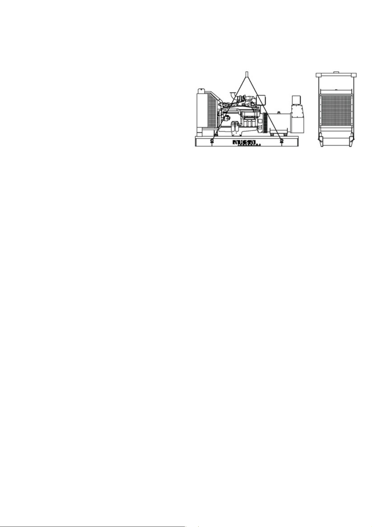
Figure 4.1. Lifting generating set by using a winch
Warning
! Never lift the generating set by attaching to the engine
or alternator lifting lugs.
! Ensure the lifting rigging and supporting structure is
One of several types of control systems and panels
(item 12) may be fitted to control the operation and
output of the set and to protect the set from possible
malfunctions. Section 15 of this manual provides detailed
information on these systems and will aid in identification
of the control system fitted on the generating set.
4.INSTALLATION, HANDLING AND STORAGE
4.1. General
Once the size of the generating set and any associated
control systems or switchgear have been established,
plans for installation can be prepared. This section
discusses factors important in effective and safe installation
of the generating set.
4.2. Canopies
Installation and handling is simplified when the generating
set has been equipped with a canopy. The canopy also
gives protection from the elements and protection from
unauthorized access.
4.3. Moving the Generating Set
The generating set base frame is specifically designed
for ease of moving the set. Improper handling can
seriously damage components.
in good condition and is suitably rated.
! Keep all personnel away from the generating set when
it is suspended.
! If the generating set is going to be lifted, it should be
lifted by the lifting points fitted on canopied sets and
most open sets.
4.4. Location
In order to start to consider the possible layouts for a
site, the following criteria must first be determined:
- The total area available and any restrictions
within that area (i.e. buried or overhead services)
- A forced ventilation system is required for the
equipment, which draws sufficient cooling and aspiration
air into the room at the back of the alternator and
discharges the air from in front of the engine. Dependent
upon the layout of the building, it may be necessary to
install additional ductwork to achieve the airflow required..
- The access into the building, initially for the delivery
and installation of the equipment, and afterwards for
servicing and maintenance of the equipment.
- Protection from the elements such as rain, snow, sleet,
wind driven precipitation, flood water, direct sunlight,
freezing temperatures or excessive heat.
10
Page 14

- Protection from exposure to airborne contaminants
The following formula may be used to calculate the
such as abrasive or conductive dust, lint, smoke, oil mist,
vapors, engine exhaust fumes or other contaminants.
- Protection from impact from falling objects such as
trees or poles, or from motor vehicles or lift trucks.
- Clearance around the generating set for cooling and
access for service: at least 1 meter around the set and
at least 2 meters headroom above the set.
- Access to move the entire generating set into the
room. Air inlet and outlet vents can often be made
removable to provide an access point. Limited access
to unauthorized personnel.
- If it is necessary to locate the generating set outside
of the building, the generating set should be enclosed
in a canopy. A canopy is also useful for temporary
installations inside or outside the building.
4.5. Base and Foundation
minimum foundation depth:
k
t = ---------------
d x w x l
t = thickness of foundation in m
k = net weight of set in kg
d = density of concrete (take 2403 kg/m
2
w = width of foundation in (m)
l = length of foundation in (m)
The foundation strength may still vary depending on
the safe bearing capacity of supporting materials and
the soil bearing load of the installation site, therefore
reinforced gauge steel wire mesh or reinforcing bars or
equivalent may be required to be used.
)
Note: Special foundation are unnecessary.
A level and sufficiently strong concrete floor is adequate.
The responsibility for the foundation (including seismic
considerations) should be placed with a civil or structural
engineer specializing in this type of work.
Major functions of a foundation are to:
Support the total weight of the generating set.
Isolate generator set vibration from surrounding
structures.
To support the structural design, the civil engineer will
need the following details:
- the plant's operating temperatures
- the overall dimensions of the proposed foundation
mass.
- the mounting and fixing arrangements of the generator
bed-frame.
Concrete Foundations
The foundation will require at least seven days between
pouring the concrete and mounting the generating set
to cure. It also essential that the foundation should be
level, preferably within ± 0,5
o
of any horizontal plane
and should rest on undisturbed soil.
11
Page 15

Vibration Isolation
Each generating set is build as a single module with the
engine and alternator coupled together through a
coupling chamber with resilient mounting to form one
unit of immense strength and rigidity. This provides both
accuracy of alignment between the engine and alternator
and damping of engine vibration. Thus heavy concrete
foundations normally used to absorb engine vibration
are not necessary and all the generator requires is a
level concrete floor that will take the distributed weight
of the unit.
any wall, tank or panel within the room.
4.6.2. Inlet and outlet attenuators with weather
louvers
The inlet and outlet attenuators should be installed
within a wooden frame and are based on 100 mm.
Airways with 200 mm. Acoustic modules. The attenuators
should be fitted with weather louvers with a minimum
50 % free area, good airflow profile and afford low
restriction airflow access.
The weather louvers should have bird/vermin mesh
screens fitted on the inside, but these screens must not
Foundation
A reinforced concrete pad provides a rigid support to
prevent deflection and vibration. Typically the foundation
should be 150 mm to 200 mm ( 6 to 8 inches) deep
and at least as wide and long as the generating set. The
ground or floor below the foundation should be properly
prepared and should be structurally suited to carry the
weight of the foundation pad and the generating set. (If
the generating set is to be installed above the ground
floor the building structure must be able to support the
weight of the generating set, fuel storage and accessories).
If the floor may be wet from time to time such as in a
boiler room, the pad should be raised above the floor.
This will provide a dry footing for the generating set
and for those who connect, service or operate it. It will
also minimize corrosive action on the base-frame.
impede the free flow of cooling and aspiration air.
The outlet attenuator should be connected to the
radiator ducting flange with a heat and oil resistant
flexible connection
4.6.3. Combustion Air Inlet
Air for engine combustion must be clean and as cool
as possible. Normally this air can be drawn from the
area surrounding the generating set via the engine
mounted air filter. However, in some cases due to dust,
dirt or heat the air around the set is unsuitable. In these
cases an inlet duct should be fitted. This duct should run
from the source of clean air (outside the building, another
room, etc) to the engine mounted air filter. Do not
remove the air filter and mount it at a remote location
as this can increase the possibility of dirt leaking through
the ductwork and into the engine inlet.
Levelling
A poor foundation may result in unnecessary vibration
of the plant.
Connections
All piping and electrical connections should be flexible
to prevent damage by movement of the plant. Fuel and
water lines, exhaust pipes and conduit can transmit
vibrations at long distances.
4.6. Room Design Guidance Notes
4.6.1. Room size allowance
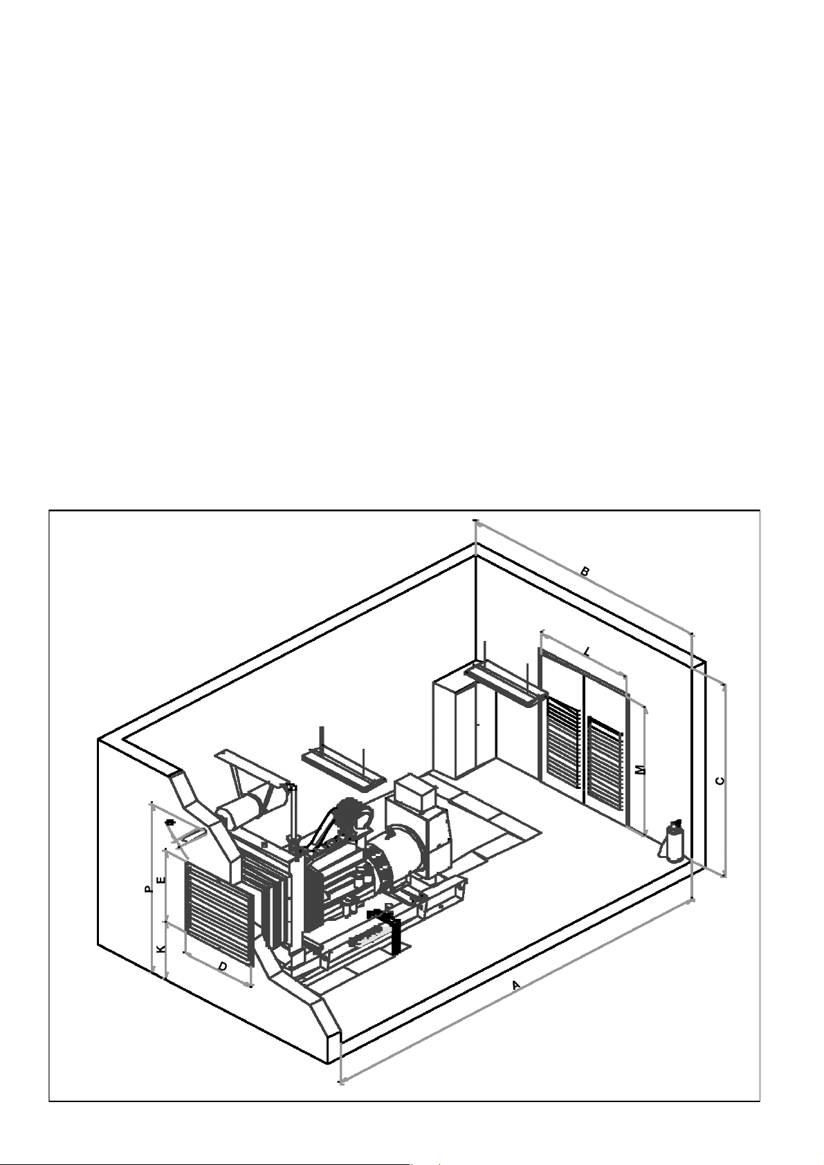
The dimensions as indicated A & B allow for good
maintenance /escape access around the generator. Ideally
you should allow a minimum distance of 1 meter from
4.6.4. Exhaust systems
The exhaust systems shown on the layout drawings are
supported from the ceiling. Should the building
construction be such that the roof supports were unable
to support the exhaust system, a floor standing steel
exhaust stand will be needed. Exhaust pipes should
terminate at least 2,3 m above floor level to make it
reasonable safe for anyone passing or accidentally
touching.
It is recommended that stainless steel bellows be fitted
to the engine exhaust manifold followed by rigid pipe
work to the silencer.
12
Page 16
It is good installation practice for the exhaust system
The air inlet and outlet openings should be large enough
within the generator room to be insulated with a
minimum of 50 mm. of high density, high temperature
mineral insulation covered by an aluminium over clad.
This reduced the possibility of operator burn injury and
reduces the heat being radiated to the operating
generator room.
4.6.5. Cooling and Ventilation
The engine, alternator and exhaust piping radiate heat
which can result in a temperature high enough to
adversely affect the performance of the generating set.
It is therefore important that adequate ventilation is
provided to keep the engine and alternator cool. Proper
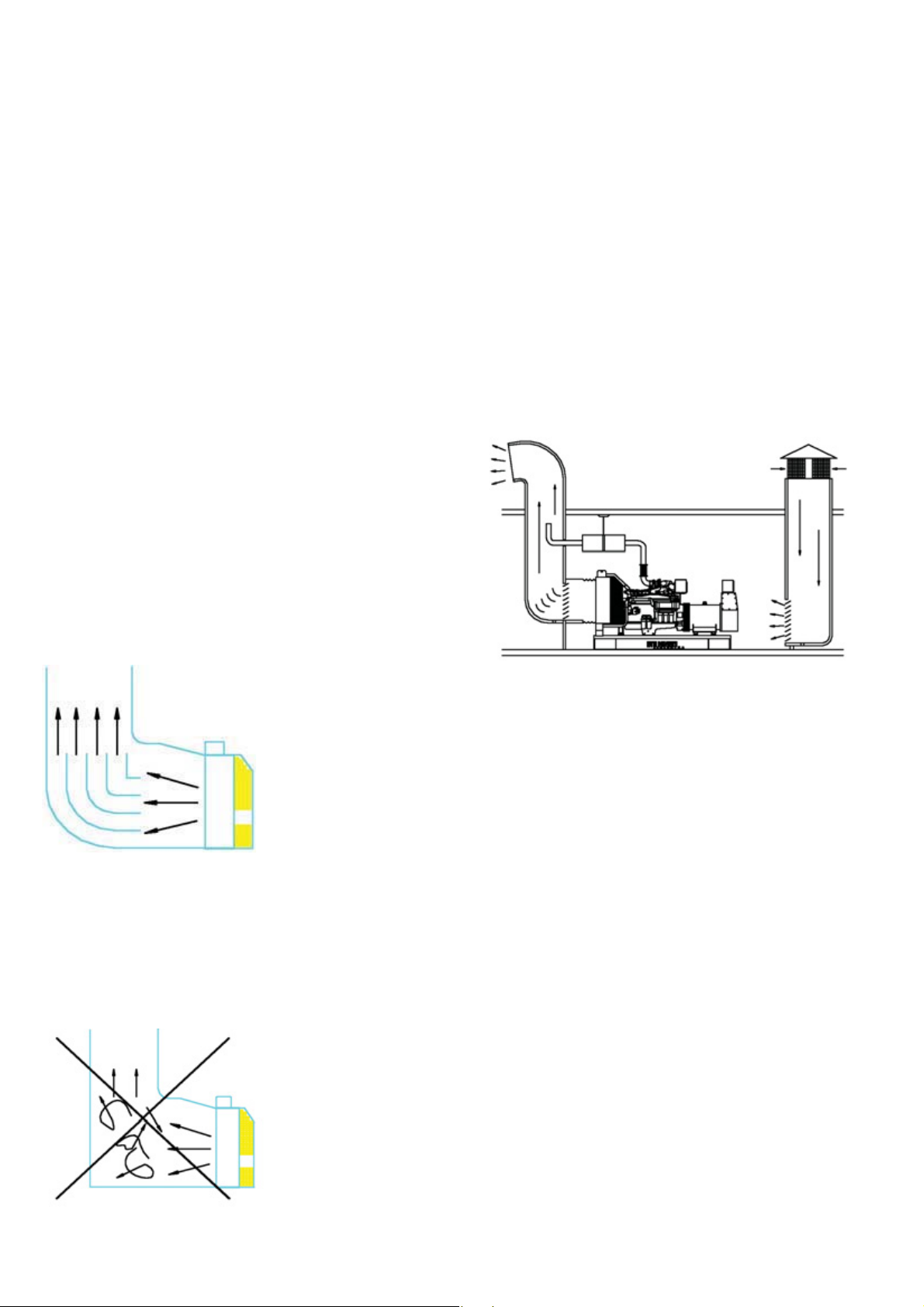
air flow, as shown in Figure 4.4. requires that the air
comes in at the alternator end of the set, passes over
the engine, through the radiator and out of the room
via a flexible exhaust duct. Without the ducting of the
to ensure free flow of air into and out of the room. As
rough guide the openings should each be at least 1,5
times the area of the radiator core.
Both the inlet and outlet openings should have louvers
for weather protection. These may be fixed but preferably
should be movable in cold climates so that while the
generating set is not operating the louvers can be closed.
This will allow the room to be kept warm which will
assist starting and load acceptance. For automatic starting
generating sets. If the louvers are movable they must
be automatically operated. They should be programmed
to open immediately upon starting the engine
hot air outside the room, the fan will tend to draw that
hot air around and back through the radiator, reducing
the cooling effectiveness.
Figure 4.2.
Directing the
air thrown from
the radiator
with deviating wings
Sharp corners on the radiator hot air outlet
channel or its chimney must be avoided.
Some rearrangements to turn thrown air should be
done (Figure 4.2. and 4.3.)
Figure 4.4. Air ventilation
4.6.6. Cable systems
The layout drawings assumes that the change-over,
switch-gear is external to the generator room and
located in the power distribution room. Specific project
requirements can affect this layout.
The power output cables from the generator output
breaker to the distribution panel must be of a flexible
construction.
The flexible power cables as installed should be laid up
in trefoil, placed on support trays/ladder rack in the
trench with the recommended inter-spacing an
Figure 4.3. Weak ventilation
segregated from the system control cables.
The cables should be correctly supported and rated for
the installation/ambient conditions.
The flexible single core power cables when entering
any panel must pass through a non-ferrous gland plate.
4.6.7. Change - over panels
Should the change-over panel with in the generator
room.
13
Page 17
For change-over cubicles up to 400 Amp. rating the wall
Air inlet should be at rear of the alternator to allow
mounting panel of maximum depth 350mm. can be
mounted directly above the cable trench in the side
access area without causing too many problems.
For change-over cubicles from 800 Amp. and above a
floor standing panel is used which needs additional space
to allocated. A minimum of 800 mm for rear access
should be allowed.
4.6.8. Generator Sets
Up to 680 kVA generators include base fuel tanks. Free
standing tanks can be provide but additional room space
will required.
Canvas ducting between the radiator and ductwork or
attenuator should be a minimum of 300 mm.
adequate circulation.
4.6.9. Doors
Doors should always open outwards. Make allowance
for the generator to be moved into the room by using
double doors at the attenuator space.
4.6.10. Inlet and outlet louver s
The inlet and outlet weather louver s should be installed
within a wooden frame with a minimum 50 % free area,
good airflow profile and low restriction airflow access.
The weather louvers should have bird/vermin mesh
screens fitted on the inside, but must not impede the
free flow of cooling and aspiration air.
The outlet weather louver should be connected to the
radiator ducting flange with a heat and oil resistant
flexible connection.
14
Figure 4.5. Generating set room
Page 18
$
OHQJWK
%
:LGWK
&
+HLJKW
'LDPHQWH
ULQFK
3P
$3'$ 11,5
1$ 1$ 1$ 1$ 1$ 1$ 1$ 1$ 1$ 1$ 1$
$3'$ 15,5
1$ 1$ 1$ 1$ 1$ 1$ 1$ 1$ 1$ 1$ 1$
$3'$ 20
$3'$ 25
$3'& 30
$3'$ 33
$3'& 43
$3'$ 44
$3'$ 60
$3'& 66
$3'$ 66
$3'$ 70
$3'$ 93
$3'& 110
$3'& 145
$3'$ 150
$3'& 175
$3'& 200
$3'$ 215
$3'$ 220
$3'&' 275
$3'& 275
$3'$ 275
$3'$ 300
$3'& 330
$3'& 350
$3'& 385
$3'& 412
$3'& 550
$3'& 650
$3'& 680
$3'& 825
h
$3'& 890
h
$3'& 1000
h
$3'& 1100
h
5DGLDWRU+RW
$LU2XWOHW
2SHQLQJV
/RXYHUVP
$LU
,QOHW
2SHQLQJ
V7RWDO
$UHD
5RRPV
'RRU
'LPHQVLRQV
P
*HQVHW
6WDQG
%\
3RZHU
.9$
0RGHO
*HQHUDWLQJ6HW
'LPHQVLRQVP
/HQJWK :LGWK +HLJKW
5RRP'LPHQVLRQP
([KDXVW
'(. P /0
Page 19

5. FUEL SYSTEM
Ash Not to exceed 0,02 mass percent
5.1. General
Dependent upon the specific site layout, the fuel can
be supplied to the engine either from:
1. Directly from sub-base fuel tank located
under the generating set.
2. An intermediate daily service tank located
within the plant room or generator enclosure,
which is automatically refilled from a bulk
storage tank
3. Directly from the bulk storage tank, provided
that the outlet connection from this tank is at
least 500 mm higher than the base on which
the generator is mounted.
It is very important that the fuel oil purchased for use
in any engine be as clean and water-free as possible.
Dirt in fuel the fuel can clog injector outlets and ruin
the finely machined precision parts in the fuel injection
(ASTM D482) (0,05 mass percent with
lubricating oil blending)
Acid Number Not to exceed 0,1 Mg KOH per
(ASTM D664) 100 ML
Lubricity 3100 grams or greater
Diesel Fuel Property Definition
Ash - Mineral residue in fuel. High ash content leads to
excessive oxide build up in the cylinder and/ or injector.
Cetane Number - Ignitability of fuel. The lower the cetan
number, the harder it is to start and run the engine.
Low cetane fuels ignite later and burn slower.
This could lead to explosive detonation by having
excessive fuel in the chamber at the time of ignition.
In cold weather or with prolonged low loads, a higher
cetane number is desirable.
system. Water in the fuel will accelerate corrosion of
these parts.
5.2. Fuel Oil Recommendations
The following fuel oil specification is typical
Fuel oil Recommended Physical Properties
Specifications.
Viscosity 1,3 to 5,8 centi strokes
(ASTM D445) (1,3 to 5,8 mm per second) at
40
Cetane Number 40 Minimum above 0
(ASTM D613) 45 Minimum below 0
o
C (104∞F)
o
C (32oF)
o
C (32oF)
Sulphur Content Not to exceed 0,5 mass percent
(ASTM D129 or 1552)
Water and Sediment Not to exceed 0,05 volume
(ASTM D1796) percent
o
Density 42 to 30
(ASTM D287) (0,816 to 0,876 g/cc at 15
Cloud Point 6
o
C (10oF) below lowest ambient
API gravity at 60oF
o
C)
(ASTM D287) temperature at which the fuel is
expected to operate
Cloud and Pour Points - The pour point is the
temperature at which the fuel will not flow. The cloud
point is the temperature at which the wax crystals
separate from the fuel.
The pour point should be at least 6
o
C ( 10oF ) below
the ambient temperature to allow the fuel to move
through the lines. The cloud point must be no more
than 6oC ( 10oF ) above the pour point so the wax
crystals will not settle out of the fuel and plug the
filtration system.
Sulphur - Amount of sulphur residue in the fuel . The
sulphur combines with the moisture formed during
combustion to form sulphuric acid.
Viscosity - Influences the size of the atomized droplets
during injection. Improper viscosity will lead to detonation,
power loss and excessive smoke.
Fuels that meet the requirements of ASTM or 2.0 diesel
fuels are satisfactory with fuel systems.
5.3. Base Fuel Tank
Up to 680 kVA generating sets can be supplied with or
without base fuel tanks. and the room height allows for
this feature.
16
Page 20
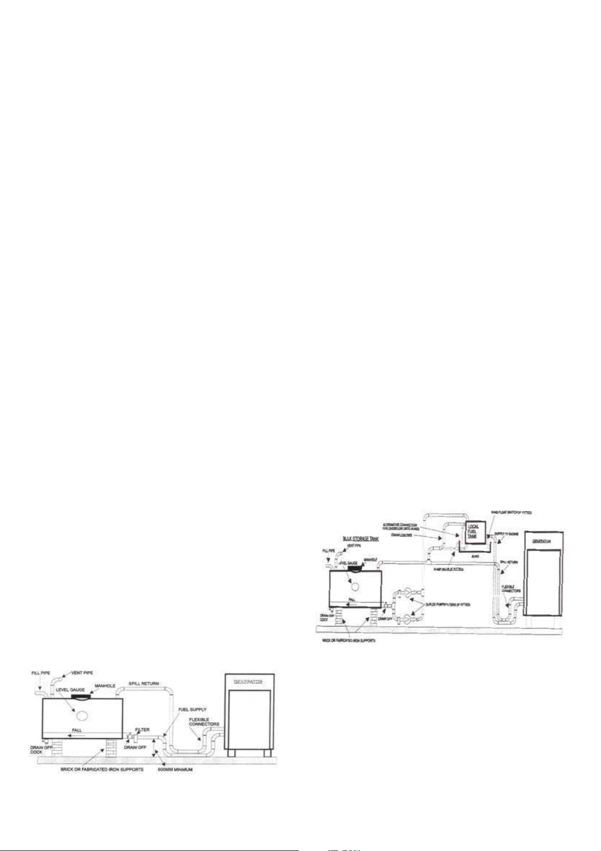
Recommended room layout drawings incorporate base
5.6. With Intermediate Fuel Tank (Fig. 5.2)
fuel tanks on the generators
This provides a self contained installation without the
additional of external fuel lines, trenches and fuel transfer
pumps. Generators with base tanks are delivered fully
connected and ready to run.
5.4.Bulk Storage Tanks
The purpose of the fuel-supply system is to store an
adequate quantity of fuel to suit the application for
which the system is intended. The bulk storage tanks
should be sized accordingly.
The filling of the tanks will be by means of a fill connection
housed in a suitable lockable cabinet located so as to
permit easy access by delivery tanker. This cabinet may
also house a contents gauge and an overfill alarm
connected to the float switch inserted into a manhole
on the tank.
Where, due to site constraints, it is not possible to
supply the engine direct from the bulk tank an
intermediate tank can be located with in the plant
room/generator enclosure which supplies fuel directly
to the engine.
This type of system can be further enhanced by the
addition of the following optional items of equipment:
1. An automatic duplex fuel transfer pump and
primaryfilter system arranged to start the standby pump
should the duty pump fail. The transfer pump(s) must
be sized to cater for the total fuel required by the engine,
i.e. fuel consumed and the spill return volumes (Fig.
5.2.);
2. A fusible link operated dead weight drop valve
designed to cut off the supply of fuel to the
intermediate tank and to transmit a signal in
5.5.Without Intermediate Fuel Tank (Fig. 5.1.)
The simplest arrangement would be to supply the engine
directly from the bulk storage tank and return the injector
spill directly to this tank. A typical arrangement for this
is shown in Fig. 5.1.
The principle limitations of this method are:
In order to gravity feed the engine, the outlet from the
bulk storage tank must be a minimum of 600 mm above
the generator plinth level;
The pressure drop of the spill return pipe work must
not exceed that detailed in the Engine Data sheet
The supply pipe work from the bulk storage tank to
the engine must be sized to allow the total volume of
fuel required by the engine to flow under gravity.
the vent of fire;
3. A fusible link operated dump valve, arranged
to dump the contents of the local tank back
into the bulk tank in the event of a fire within
the generator enclosure.
The connection details for these additional items of
equipment are indicated. See Fig. 5.2.
Fig. 5.2. With Intermediate Fuel Tank
Fig. 5.1. Without Intermediate Fuel Tank
5.7. Daily Service Fuel Tank
Separate daily service tank can be 500 litres, 1250 litres
or 2000 litres and a transfer system arranged to
automatically feed from the bulk storage tank electric
motor driven pump(s) operating from signals from a
level sensing float switch. Fuel tanks should not be made
from galvanized iron as diesel fuel oil reacts against zinc.
17
Page 21

A vent pipe should be extended to the highest point
is warm,the fuel lines should be insulated to prevent
of the fuel system installation. The diameter of the pipe
should at least match that of the fill connection. Provision
should be made to prevent the ingress of dirt.
The overflow from the daily service intermediate tank
can either be:
1.Piped directly back to the bulk storage tank;
2. Piped into the bund of the intermediate tank with a
bund level alarm system arranged to cut off the fuel
transfer pump system on detection of a spillage;
3. Piped to overflow into the bunded area.
The feed connection on the thank should not be lower
than 600 mm above the level on which the engine sits
in order to maintain a gravity feed to the engine. When
the intermediate tank is located at a lower level than
the bulk storage tank it is essential that a solenoid valve
be incorporated into the transfer line. All final connections
to the engine should be in flexible hose to restrict
vibration transmission through the pipe.
the fuel and piping from picking up any excess heat. All
pipes should be inspected for leaks and general condition,
including cleanliness before installation. Back flush all
lines to the tank before start-up to avoid pulling excess
dirt into the engine and fuel piping system. After
installation, the air should be bled from the fuel system.
A petcock should included at some high point in the
system to allow air removal.
Use plugged tees, not elbows, to make piping bends.
This will allow for cleaning by removing the plugs and
flushing out the lines. All threaded pipe fittings must be
sealed with a suitable paste.
Caution: Do not use tape to seal fuel line fittings. Pieces
of tape could shear off an jam in the pump or injectors.
5.9. Fuel Return Lines
Fuel return lines take the hot excess fuel not used in
the engine cycle a way from the injectors and back to
either the fuel storage tank or the day tank. The heat
5.8. Determining Pipe Sizes
Minimum pipe sizes are determined by the size of the
inlet to the fuel transfer pump. The pipe inner diameter
must be a least as large as the transfer pump inlet. If the
piping must carry the fuel over long distances, the pipe
size must be increased. An auxiliary transfer pump at
the tank outlet may also be needed to avoid high suction
pressure within the piping. In all cases, excessive fuel line
suction pressures must be avoided. At high suction
pressures the fuel vaporize in the piping and the fuel
supply to the engine will be decreased. When sizing
piping, always remember to account for pressure drop
across filters, fittings and restriction valves. A flex connector
must be added to isolate the engine vibration from the
fuel piping. If this vibration is not isolated, the piping
could rupture and leak. The flexible connector must be
as close to the engine transfer pumps as possible.
Any expanse of exposed piping must be properly
supported to prevent piping ruptures. Use pipe hangers
to isolate vibration from the system. Exposed fuel piping
must never run near heating pipes, furnaces, electrical
wiring or exhaust manifolds. It the area around the piping
from the excess fuel is dissipated in the tank.
Caution: Never run a fuel return line directly back to
the engine fuel supply lines. The fuel will overheat and
break down.
The fuel return lines should always enter the storage
or day tank above the highest fuel level expected. This
statement is true for all Cummins powered engines with
the PT fuel system (NT, K range). However with sets
using the B series, C series engines drain lines for fuel
will cause siphoning back through the supply line and
result in hard starting if installed above the fuel level.
The fuel return line should never be less than one pipe
size smaller than the fuel supply line.
WARNING!
- The fuel must be clean and must not contain any water
- Fuel pipes must best made of black pipe, not galvanized
pipe.
- When the engine stops, there should not be any
gravitational free flow in the fuel pipes towards of the
engine.
18
Page 22
- The fuel temperature is a critical factor for appropriate
- In fuel system line, using the water filter separators will
working conditions of the engine. Fuel temperature
o
above 71
C, due to expansion of the fuel, will decrease
prevent the injectors and fuel pump and it usefull for
healthy working of the engine.
the engine output power.
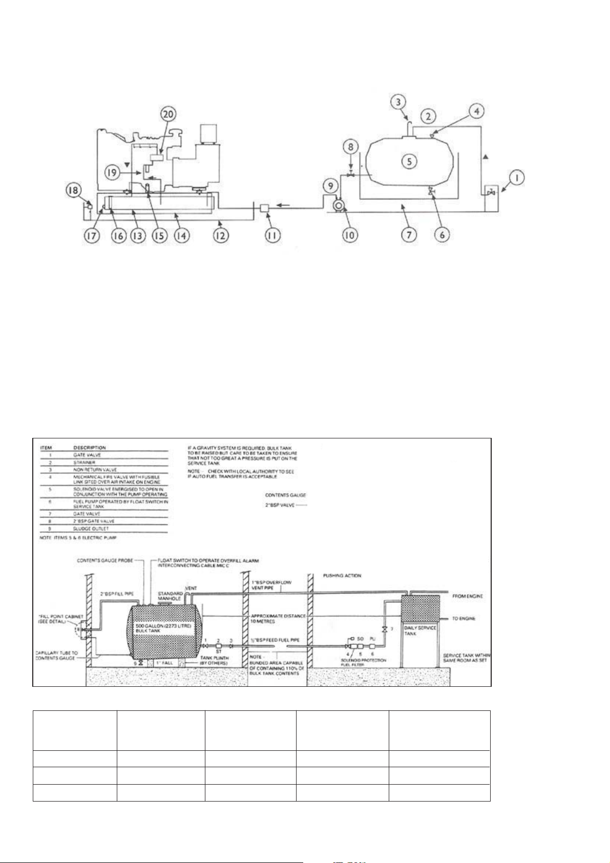
Figure 5.3. Typical fuel installation using a base tank fed from a bulk tank
1. Fill cabinet with overfill alarm and gauge
2.Tank fill line
3. Vent line
4. Contents gauge
5. Bulk storage tank
6. Sludge drain
7. Bund tank
8. Outlet valve
9. Supply line to day tank
10. Electric fuel transfer pump
11. Electrical fuel shut off valve
12. Optional band
13. Day tank incorporated in base frame
14. Float Control switches
15. Manuel fill and vent
16. Level gauge
17. Drain
18. Leakage alarm unit (optional)
19. Fuel filter
20. Engine fuel pump
Figure 5.4. Suggested Installation for Bulk and Set Tanks
Generating Set
Stand by Power
40 - 800
800 - 1500
1500 - 2200
Maximum Fuel Pipe
Length (m)
6
6
6
Maximum Ver tical
Height (m)
0.9
0.9
0.9
Table 5.1 Recommendations for fuel piping
Maximum Pipe
Fittings Quantity (m)
6
6
6
19
Recommended Pipe
Diameter
(inch)
1”
1 1/2”
2”
Page 23

6. WATER TREATMENT
6.1. General
The engine cooling system is subject to rust and cavitation
attacks. To minimize the severity of this condition an
anti-corrosive agent can be added to totally clean and
limpid coolant water.
An antifreeze solution is also required to prevent freezing
of the coolant in the cold weather.
6.2. Engine Coolant
Water for coolant should be clean and free from any
corrosive chemicals such as chlorides, sulphates and
acids. It should be kept slightly alkaline with a pH value
in the range 8,5 to 10,5
Generally, any water which is suitable for drinking can
be used, with treatment as described below.
6.3. Engine Warming
Where thermostatically controlled immersion heaters
operating from the mains supply are fitted in cooling
system these maintain the temperature of the coolant
in cold weather.
A heater alone, fitted in the radiator will not be adequate
for starting or preventing freezing, so an antifreeze
mixture should be used.
7. EXHAUST SYSTEM
7.1. Sizing
An exhaust system should be designed to dispel the
exhaust gases to atmosphere at the nearest convenient
point in an installation. The length of the run and the
number of changes in direction should be kept to a
minimum to avoid exceeding optimum.
Protection against corrosion
Supplemental Coolant Additive is required to protect
the cooling system from fouling, solder blooming and
general corrosion.
The use of antifreeze is also recommended as DCA4
concentrations are dependent upon the presence of
antifreeze. Antifreeze also interacts with DCA4 to
provide greater corrosion and cavitation protection.
Procedure for Treating Coolant
1. Add the required amount of water to mixing container
and dissolve in the required quantity of DCA.
2. Add the required amount of antifreeze, if used, to the
water solution and mix thoroughly.
3. Add the coolant to the cooling system
Cold Weather Protection
The calculation of the effect on the back pressure is
based upon the restriction through the straight lengths
of pipe, the bends and the silencers. The smaller the
bore of the pipe, the greater its length and the more
times it changes its direction, the greater is its resistance
to flow.
The back pressure limit for most Cummins engines is
3 ins Hg (76 mm Hg)
Take an estimate of the size of the pipe by starting with
the bore of the exhaust flange off the manifold and
increasing the size by 1” for each 20 ft length or 3 x
90∞ bends.
7.2. Routing
Once the final size and route of the pipe work and the
silencer have been established, the exhaust route can
Antifreeze must be added to the coolant where there
is any possibility of freezing to protect the engine from
damage due to coolant freezing.
A 50% antifreeze / 50 % water mixture is recommended
because DCA4 concentrations are dependent upon
the presence of antifreeze. The dosage of DCA4 must
be increased to higher concentration if antifreeze is not
added to the coolant. A low- silicate antifreeze is
recommended.
be determined, taking into account the following factors:
A flexible bellows unit must be fitted on the engine
connection to allow the engine to move on its mountings;
If the silencer is to be located within the plant room,
due to its physical size and weight need to be supported
from the floor;
It may be necessary to install expansion joints at each
change of direction to compensate for the thermal
growth in the pipe during operation;
20
Page 24
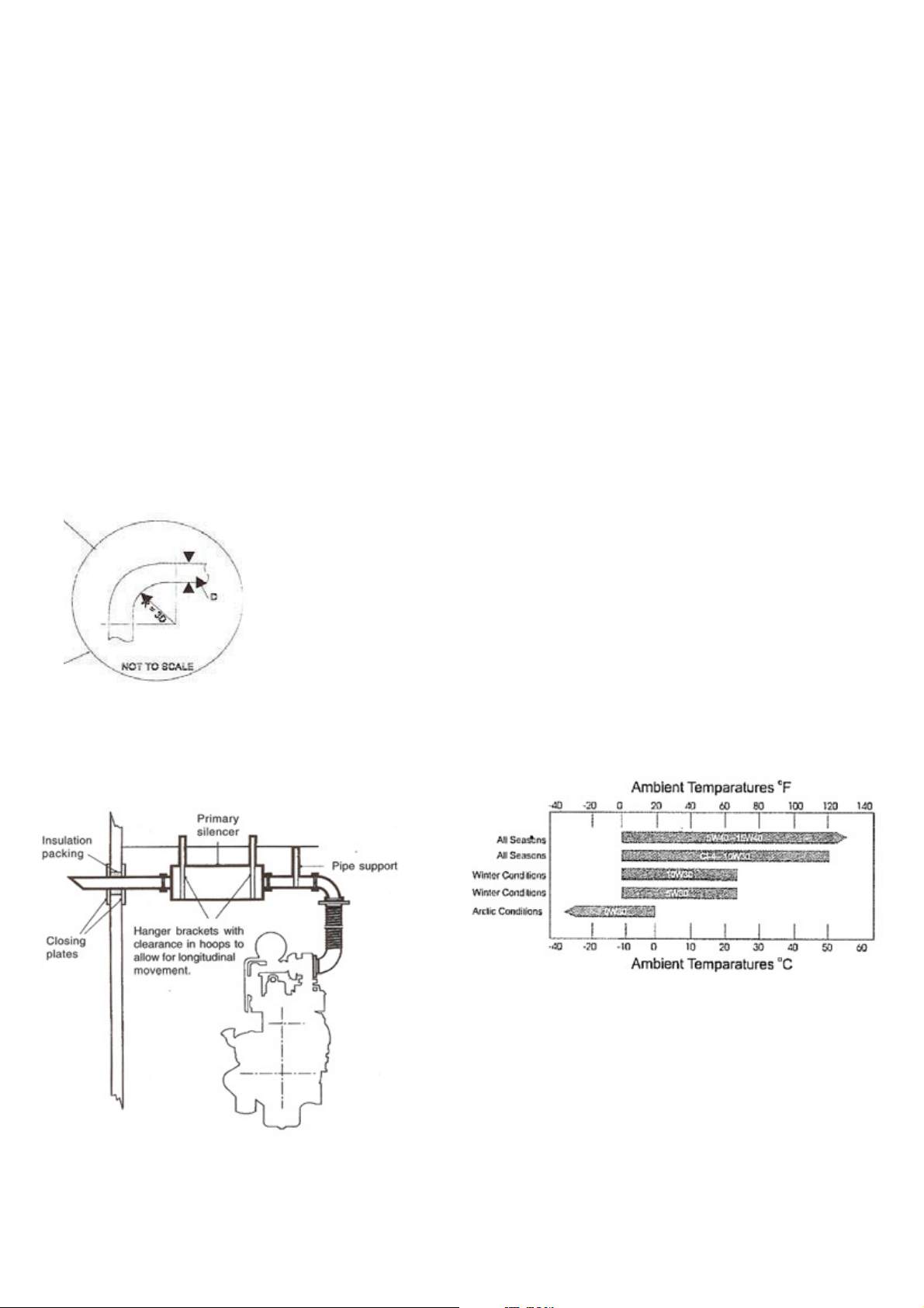
The inner radius of a 90o bend should be 3 times the
diameter of the pipe; Fig. 7.1.
The primary silencer should be mounted as close as
possible to the engine;
The termination point should not be directed at
combustible materials/structures, into hazardous
atmospheres containing flammable vapors, where there
8. LUBRICATING OIL
Oil system of diesel engine is one of the most important
elements of the engine. Correctly made engine overhaul
( this subject includes oil change periods, filter change
periods, paying attention about selecting the true type
of oil ) prolongs the life cost of the engine.
is a danger that the gases will re-enter the plant room
through the inlet air vent, or into any opening to other
buildings in the locality.
All rigid pipe work should be installed in such a manner
that the engine's exhaust outlet is not stressed. Pipes
should be routed so that they are supported by fixtures
to the building fabric or by existing structural steelwork
where such methods are acceptable;
8.1. Oil Performance Properties
The American Petroleum Institute (API) the American
Society for Testing and Materials (ASTM) and Society
of Automotive Engineers (SAE) has developed and
preserved a system in order to classify the lubrication
oils for their performance categories.
8.2. Lubrication Recommendations for Engine
Aksa recommends that high quality multi grade SAE
15W/40 high service engine oil in diesel engines are
o
used. At ambient temperatures above -15
C is 15W40.
The minimum API oil quality levels recommended for
use is CH / CI-4, CH or CI-4 can be used in areas
where CF4 oil is not yet available, but the oil interval
must be reduced API CA, CB, CC, CD, CE, CG4
categories not recommended, do not use.
Fig. 7.1. Exhaust bend and radius
Fig. 7.2. Exhaust system
Figure: 8.1. Recommended SAE Oil Viscosity
Grades v.s. Ambient Temperatures
21
Page 25
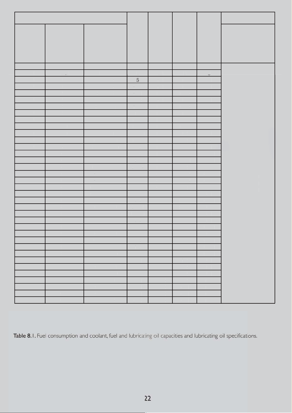
3RZHU
N9$ /+ /LWHU /LWHU /LWHU
$3'$ 11,5 CZ380
$3'$ 15,5 CZ480
$3'$ 20 CY485D
$3'$ 25 CY490D
$3'& 30 4B3,9G2
$3'$ 33 CY490ZD
$3'& 43 4BT3,9G2
$3'$ 44 YC4108D
$3'$ 60 YC4108ZD
$3'& 66 4BTA3,9G2
$3'$
$3'$ 70
TD226B-4D
$3'$ 93 4M3L-D60EF
$3'& 110 6BT5.9G2
$3'& 145 6BTAA5.9G2
$3'$
$3'& 175 6CTA8.3G2
$3'& 200 6CTA8.3G2
$3'$ 215
WD615.68D-15
$3'$ 220
LR6S4L-D60EF
$3'&' 275 6LTAA8.9G2
$3'& 275 MTA11G2A
$3'$ 275
LR6S4L-D60AEF
$3'$ 300
WD618-42D
$3'& 330 NTA855G1A
350 MTAA11G3
$3'& 350 NTA855G1B
$3'& 385 NTA855G2A
$3'& 412 NTAA855G7
$3'& 550 KTA19G4
$3'& 650 KTAA19G6
$3'& 680 KTAA19G6A
$3'& 825 KTA38G2
$3'& 890 KTA38G2A
$3'& 1000 KTA38G2A
$3'& 1100 KTA38G5
2LOVHSFLILFDWLRQ
*HQHUDWLQJ 6HW
)XHO
&
)XOOORDG
)XHO7DQN
&DSDFLW\
&RRODQW
&DSDFLW\
2LO&DSDFLW\
0RGHO (QJLQH0RGHO
1RW/XEULFDWLQJRLO
YLVFRVLW\OHYHOZLOO
EHFKRRVHQIURP7DEOH
DFFRUGLQJWRWKH
DPELHQWWHPSHUDWXUH
,
$
20
C
D
$
25
CY490D
&
30
4B3,
$
33
CY490
&
3
4BT
$3'$
08D
$
60YC4108ZD
&
6
$
66
L
3Z
$
70
TD22
$
93
4
F
&
0
6BT5
2
&
5
2
$
T
D
&
75
6CT
2
&
6CT
$
215
WD615.68
5
$
220
LR6S
F
&'
75
6LT
&
5
$
275
F
$
300
2D
&
330
NTA855G
&
3
&
350
855G
&
385
N
&
2
N
&
KTA19G4
&
650
9G6
&
680
K
9G6
&
825
K
2
&
890
&
&
00
K
+
$
6
$3'
$3'
$3'
$3'
$3'
$3'
$3'
$3'
$3'
$3'
$3'
$3'
$3'
$3'
$3'
$3'
$3'
$3'
$3'
$3'
$3'
$3'
$3'&
$3'
$3'
$3'
$3'
$3'
$3'
$3'
$3'
$3'
$3'
$3'
Y485
9G2
4
44 YC41
6 4BTA3,9G2
66 LR4B3Z
11
14
150
150
1
200
2
27
50 MTAA11G3
41
1
3,9G2
R4B
6B-4D
M3L-D60E
.9G
6BTAA5.9G
BD226B-6
TBD226B-6D
A8.3G
A8.3G2
4L-D60E
AA8.9G2
MTA11G2A
LR6S4L-D60AE
WD618-4
NTA
TA855G2A
TAA855G7
KTAA1
TAA1
TA38G
KTA38G2A
KTA38G2A
TA38G5
ZD
D-1
1A
1B
$3,&+
$3,&
$3,&,
$3,&,
$3,&)
3,&)
A
Page 26

9. ELECTRIC STARTING SYSTEMS
Electric starting systems are generally used on all gensets. The power source for electric starting systems is
a 12 or 24 VDC battery system. The starting voltage is
determined by engine size, 24 VDC being used for
larger engines to reduce starting current and hence
Ensure that your battery is not uncharged.
9.4. Maintenance Free Batteries
Ensure that all battery connections are correct and
batteries are always charged. After that there is not any
procedure for this batteries.
cable size. Control of starting is via a start solenoid
which is controlled by the gen-set control system.
9.1. Battery Systems
Batteries are of two types - lead acid and NiCad. Lead
acid batteries are generally used, being the least
expensive. NiCad batteries are used where longer life,
etc., is required.
9.2. Maintenance Batteries
Warning
- Do not smoke or allow sparks, flames or other sources
of ignition around batteries. Hydrogen gas generated
by charging batteries is explosive.
- Wear an acid resistant apron and face shield or goggles
when servicing the battery. If electrolyte is spilled on
skin or clothing, flush immediately with large quantities
9.5. Starting Aids
It is customary to maintain coolant temperatures above
o
40
C min. To promote quick starting on an emergency
generating plant. Thermostatically controlled immersion
heaters, deriving their supply from the primary source
of power are fitted in the engine cooling system to
provide this heating.
10. ELECTRICAL CONNECTION
Only full qualified and experienced electrical technicians
should carry out electrical installation, service and repair
work.
Warning:
- Make electrical connections in compliance with relevant
Electrical Codes, Standards or other requirements.
of water.
- Take out the metallic things in your wrist and protect
your wrist and hand.
- Disconnect the battery negative (earth) lead first and
reconnect last.
- Always ensure that battery charging is carried out in
a well ventilated area.
The starting batteries should be located as close as
possible to the generating set while still being accessible
for servicing. This will prevent electrical losses
9.3. Battery Maintenance
Keep the top of the battery and its terminals clean.
Cover the battery terminals and its connections with
Vaseline.
Tighten the terminals but not tighten it hardly.
Control the electrolyte level periodically. It must be
10 mm above the plates.
Control the abrasion in the charge alternator belt
and check periodically the belt tension according to
producer' recommendation.
10.1. Cabling
Due to movement of generating sets on their vibration
mounts, the electrical connection to the set should be
made with flexible cable.
The cable must be suitable for the output voltage of
the generating set and the rated current of the set. In
determining the size, allowances should be made for
ambient temperature. Method of installation, proximity
of other cables. etc.
All connections should be carefully checked for integrity.
Current carrying capacity of power cables that will be
given in table 10.1 and the cable cross sections which
must be used according to the generating set power
has been given in table 10.2. On the other hand, there
is a one more important point while cable cross sections
are being selected. If the distance between load and
generator is too length, voltage falling at the load side
can be too much at the transient current duration. The
voltage drop across a cable can be determined as
follows:
23
Page 27
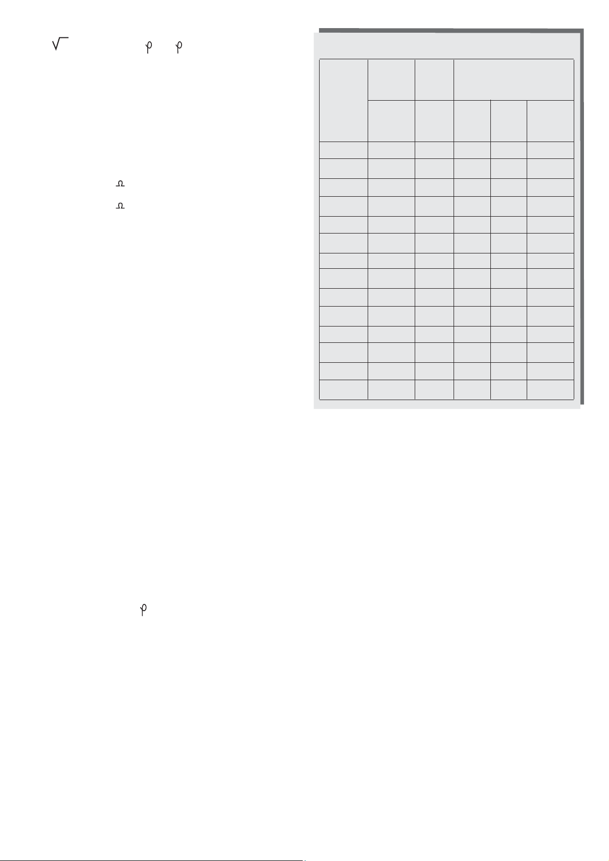
3 x L x I x (R Cos +Sin )
e = ----------------------------------------- 1000
e = Voltage drop (V)
I = Rated current (A)
L = Length of conductors (m)
R = Resistance ( /km to VDE 0102)
X = Reactance ( /km to VDE 0102)
10.2. Protection
The cables connecting the generating set with the
distribution system are protected by means of a circuit
breaker to automatically disconnect the set in case of
overload or short circuit. (Manual models only)
Cable
Section
mm2
Soil
Multiple
Core
25oC
at Air
Multiple
Core
Multiple
Core
40oC
at Air
Multiple
Core
2,5 36 25 22 25 21
4 46 34 30 33 28
6 58 44 38 42 36
10 77 60 53 57 50
16 100 80 71 76 67
25 130 105 94 101 88
35 155 130 114 123 110
50 185 160 138 155 138
70 230 200 176 191 170
95 275 245 212 228 205
HO07RN-F
10.3. Loading
When planning the electrical distribution system, it is
important to ensure that a balanced load is presented
to the generating set. If loading on one phase is
substantially higher than the other phases it will cause
over heating in the alternator windings, imbalance in
the phase output voltage and possible damage to
sensitive 3 phase equipment connected to the system.
Ensure that no individual phase current exceeds the
current rating of the generating set. For connection to
existing distribution system, it may be necessary to
reorganize the distribution system to ensure these
loading factors are met.
10.4. Power Factor
The power factor (Cos ) of the connected load should
be determined. Power factors below 0,8 lagging
(inductive) can over load the generator. The set will
provide its kilowatt rating and operate satisfactorily
from 0,8 lagging to unity power factor (1.0) Particular
attention must be given to installations with power
factor correction equipment such as capacitors to
ensure that a leading power factor is never present.
This will lead to voltage instability and may result in
damaging over voltages. Generally whenever the
generating set is supplying the load any power factor
correction equipment should be switched off.
120 315 285 248 267 245
150 355 325 283 305 271
185 400 370 322 347 310
240 465 435 380 .... ....
Table 10.1. Current carrying capacity of power cables
(PVC - isolated YVV, NYY, 0.6/1 kV, VDE and TSE norms)
10.5. Grounding / Earthing Requirements:
The frame of the generating set must be connected to
an earth ground. Since the set is mounted on vibration
isolators, the ground connection must be flexible to
avoid possible breakage due to vibration. Ground
connection cables or straps should have at least full
load current carrying capacity and meet applicable
regulations.
10.6. Insulation Test:
Before starting the generating set after installation, test
the insulation resistance of the windings. The Automatic
Voltage Regulator (AVR) should be disconnected and
the rotating diodes either shorted out with temporary
links or disconnected. Any control wiring must also be
disconnected.
A 500 V Megger or similar instrument should be used.
Disconnect any earthing conductor connected between
neutral and earth and megger an output terminal to
earth.
24
Page 28
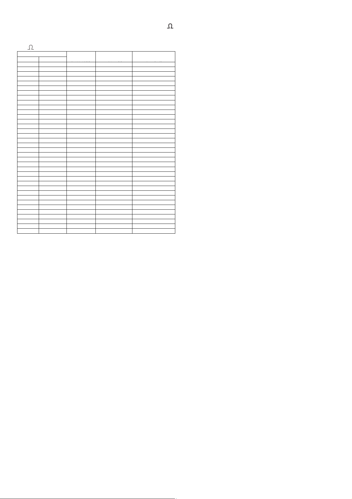
The insulation resistance should be in excess of 1M
6WDQG%\
$3'$ 11.5
$3'$ 15.5
$3'$ 20
$3'$ 25
$3'& 30
$3'$ 33
$3'& 43
$3'$ 44
$3'$ 60
C
$3'& 66
$3'$ 66
$3'$ 70
$3'$ 93
$3'& 110
$3'& 145
$3'$ 150
$3'& 175
h
$3'& 200
h
$3'$ 215
h
$3'$ 220
h
$3'&' 275
h
$3'& 275
h
$3'$ 275
h
$3'$ 300
h
$3'& 330
h
$3'& 350
h
$3'& 350
h
$3'& 385
h
$3'& 412
h
$3'& 550
h
$3'& 650
h
$3'& 680
h
$3'& 825
h
$3'& 890
h
$3'& 1000
h
$3'& 1100
h
)XOOORDG
&XUUHQWDW
&DEOHFXUUHQW
FDSDFLW\DWć
&DEOHVHFWLRQ<:6LQJOH
FRUHIRUHDFK
12. TOWING (Mobile Generating Sets)
to earth. Should the insulation resistance be less than
1M winding must be dried out.
*HQHUDWLQJ6HW
0RGHO
12.1. Preparing to Tow:
Inspect all components of the coupling equipment on
the towing vehicle and the generating set for defects
such as excessive wear, corrosion, cracks, bent metal,
or loose bolts.
Inspect tyres for condition and proper inflation. Check
that all tail lights, if equipped, are operating properly
and that all reflectors are clean and functional.
12.2. Towing:
Whenever towing a mobile generating set, remember
that manoeuvrability and stopping distance will be
affected by the weight of the trailer.
WARNING
! When mobile generating set, observe all Codes,
Standards or other regulations and traffic laws. These
include those regulations specifying required equipment
Table 10.2. Recommended single core cable cross
section at 40 oC ambient.
11. ACOUSTIC SILENCING
Control of generating set noise is becoming very
important in most installations. There is range of
components available to control the noise level.
WARNING!
Ear protection must be worn when operating or working
around an operating generating set.
11.1. Exhaust Silencers:
As discussed in Section 3.10. the exhaust silencer will
decrease sound level from the engine.
11.2. Canopies:
Section 4.2. discusses sound attenuating canopies that
lower the noise level of the entire generating set.
and maximum and minimum speeds.
! Do not permit to ride on the mobile generating set.
Do not permit personnel to stand or ride on the
drawbar or to stand or walk between the generating
set and towing vehicle.
! Avoid gradients and avoid potholes, rocks or other
obstructions and soft or unstable terrain.
! Ensure the area behind and under the mobile set is
clear before reversing.
12.3. Parking:
Park the set on a dry level area that can support it's
weight. If it must be located on a slope, park it across
the grade so that it does not tent to roll downhill. Do
not park the set on grades exceeding 15∞ .
13. STORAGE
Long term can have detrimental effects on both the
engine and alternator. These effects can be minimized
by properly preparing and storing the generating set.
11.3. Other Sound Attenuation:
For installation in buildings there are other types of
equipment such as acoustic louvers, splitter vents and
fan silencers, as well as sound absorbing wall coverings,
that can be used to reduced the noise levels of generating
sets.
13.1. Engine Storage:
The engine should be put through an engine
“preservation” procedure that includes cleaning the
engine and replacing all the fluids with new or preserving
fluids.
Page 29

13.2. Alternator Storage:
When an alternator is in storage, moisture tends to
order to avoid oxidation.
Open the battery caps and check the liquid level in
condense in the windings. To minimize condensation,
store the generating set in a dry storage area. If possible
use space heaters to keep the windings dry.
After removing the generating set from storage, perform
an insulation check as discussed in Section 10.6.
13.3. Battery Storage:
While the battery is stored, it should receive a refreshing
charge every 8 weeks up to a fully charged condition.
14. GENERAL PRECAUTIONS AND CONTROLS
WHICH MUST BE DONE BEFORE STARTING UP
THE GENERATING SET.
Make a general visual inspection on the engine and
alternator. Check if there is any breakage, crack,
indentation, leakage or looseness. Never operate the
generating set before removing any fault, if any.
Take out foreign materials such as keys, tools, cleaning
wool, papers etc. on the engine and the alternator.
Check the fuel level in day tank. Refill with fuel if it is
the cells for maintenance type battery. Add distilled
water, if necessary, so as to be 1 cm higher than the
separation. Never fill the cells with tap water, acid water
or acid.
Check if the circuit breaker outlet switch is in OFF
position.
Make sure that the emergency stop button is not
pressed.
15. GENERATING SET CONTROL SYSTEMS
To control and monitor the generating set, an electronic
control system has been used. P 300 model control
system is fitted from 20 kVA to 200 kVA. P 2020 control
system is fitted from 250 kVA to 1000 kVA. Control
panel provides a means of starting and stopping the
generating set, monitoring its operation and output and
automatically shutting down the set in the event of
critical condition arising such as low oil pressure or high
engine temperature.
low.
Check the oil level on the dipstick. Refill with an
appropriate oil if it is low. Oil level normally must be
close to the maximum level line.
Look at the water level by opening the radiator tap.
If it is inadequate add more water. Water level must be
30 mm lover than the water filling neck.
Engine cooling water must include antifreeze
according to the coolest weather conditions in the area.
A mixture of 50% antifreeze and 50% water provides
a good protection in all area.
Inspect the radiator air outlet hood, open if clogged
and clear away all obstructions in front of the air outlet.
Check the air filter gauge. Clean or replace air filter,
if necessary.
Keep the inlet opening open.
Make sure that the generating set can easily take air
from the environment.
Check the battery connection cables. Take care to
tighten the loosened battery terminals with spanner
and, cover with special substance and keep clean in
15.1. P 300, Control System with Automatic Mains
Failure
DSE, model 720 module controls generating set system.
Module has been designed to monitor the mains (utility)
supply.
15.1.1. Operation
Manual Mode of Operation
This mode activated by pressing the pushbutton. A
LED indicator beside the button confirms this action.
Press the button to begin the start sequence (There
is no Start Delay in this mode of operation). After the
fuel solenoid is energized, then the starter motor is
engaged. The engine is cranked for 10 sec. If the engine
fails to fire during this cranking attempt then the starter
motor is disengaged for 10 sec. This sequence should
continue beyond the 3 cranking attempts, the start
sequence will be terminated and Fail to Start
fault will be displayed. When the engine fires, the
starter motor is disengaged and locked out. Delayed
alarms (under speed, low oil pressure etc) will be
monitored after the end of the Safety On delay.
26
Page 30
The generator will continue to run on load
On the return of the mains supply, the Stop delay
regardless of the state of the mains supply.
If Auto mode is selected, and the mains supply is
healthy then the Remote Stop Delay Timer begins,
after which the load is transferred to the mains.
The generator will then run off load allowing the
engine a cooling down period.Selecting stop deenergises the fuel solenoid, bringing the generator
to a stop.
Automatic Mode of operation
This mode is activated by pressing the push
button. A LED indicator beside the button confirms
this action.
Should the mains (utility) supply fail outside the
configurable limits for longer than the period of
the delay start timer, the mains healthy indicator
will extinguish.
timer is initiated, once it has timed out, the load
is transferred back to the mains (utility). The
cooling timer is than initiated, allowing the engine
a cooling down period (180 sec) off load before
shutting down. Once the cooling timer expires
the fuel solenoid is de-energised, bringing the
generator to a stop. Selecting Stop de-energises
the fuel solenoid, bringing the generator to a
stop.
Test Mode of Operation
This mode is activated by pressing the push
button. A LED indicator beside the button confirms
this action. Press the button to begin the test
sequence. After the Fuel Solenoid is energised,
1
/2 second later, the Starter Motor is engaged.
then
The engine is cranked for 10 second. If the engine
Additionally, while in AUTO mode, the remote
start input is monitored. Whether the start
sequence is initiated by mains failure or by remote
start input, the following sequence is followed:
To allow for short term mains supply transient
conditions or false remote start signals, the start
delay timer is initiated. After the Fuel Solenoid is
energized, then
1
/2 second later, the starter motor
is engaged.
The engine is cranked for 10 second. If the engine
fails to fire during this cranking attempt than the
starter motor is disengaged for 10 second. Should
this sequence continue beyond the 3 cranking
attempts, the start sequence will be terminated
and Fail to Start fault will be displayed.
When the engine fires, the starter motor is
fails to fire during this cranking attempt then the
starter motor is disengaged for 10 second. Should
this sequence continue beyond the 3 cranking
attempts, the start sequence will be terminated
and Fail to Start fault will be displayed.
When the engine fires, the starter motor is
disengaged and locked out. Delayed alarms (under
speed, low oil pressure etc) will be monitored
after the end of the Safety On delay. The load
will be transferred to the generator and the set
will run on load until Auto mode is selected or
Stop is pressed.
Selecting Stop de-energises the fuel solenoid,
bringing the fuel solenoid, bringing the generator
to a stop.
disengaged and locked out.
Delayed alarms (under speed, low oil pressure
etc) will be monitored after the end of the Safety
On Delay.
If the remote start is being used and has been
configured to Remote Start is on load, or the
mains failed, the load will be transferred to the
generator.
Figure 15.1. DSE model 720 Control Module
27
Page 31
15.2. P 2020, Control System with Automatic
Mains Failure
DSE, model 5220 module controls generating set
system. Module has been designed to monitor
the mains (utility) supply.
15.2.1. Operation
Manual Mode of Operation
Check the precautions and controls starting up
the generating set.
NOTE: If a digital input configured to panel lock
is active, the LCD will display the icon. When
in panel lock, changing modules will not be
possible. Viewing the instruments and event
logs is not affected by panel lock.
To initiate a start sequence in Manual press the
pushbutton. When (the controller is in manual
button) pressing the Start button will initiate
the start sequence.
If Close generator has been selected as a control
source, the appropriate auxiliary output will then
activate.
The generator will continue to run on load
regardless of the state of the mains supply or
remote start input until the Auto mode is selected.
If Auto mode is selected, and the mains supply is
healthy with the remote start on load signal not
active, then the Remote Stop Delay Timer begins,
after which the load is disconnected. The generator
will then run off load allowing the engine a cooling
down period.
Selecting Stop bringing the generator to a stop.
Automatic Mode of Operation
NOTE: If a digital input configured to panel lock
is active, the LCD will display the icon. When
Note: There is no Start Delay in this mode of
operation.
The Fuel Solenoid is energized then the Starter
Motor is engaged.
The engine is cranked for a preset time period.
If the engine fails to fire during this cranking
attempt then the starter motor is disengaged
continue beyond the set number of attempts, the
start sequence will be terminated and fail to start
fault will be displayed accompanied by a
flashing shutdown indicator
When the engine fires, the starter motor
disengaged and locked out at a pre-set frequency
from the Alternator output. Rising oil pressure
can also be used to disconnect the starter motor,
however it canot be used for under speed or
over speed detection.
in panel lock, changing modules will not be
possible. Viewing the instruments and event
logs is not affected by panel lock.
This mode is activated by pressing the push
button. A LED indicator beside the button confirms
this action.
Should the mains (utility) supply fall outside the
configurable limits for longer than the period of
the mains transient delay timer, the mains (utility)
available Green indicator LED extinguishes.
Additionally, while in AUTO mode, the remote
start input (if configured) is monitored. If active,
the Remote Start Active indicator illuminates (if
configured)
Whether the start sequence is initiated by mains
(utility failure) or by remote start input, the
follow sequence is followed:
After the starter motor has disengaged, the Safety
On timer is activated, allowing Oil Pressure, High
Engine Temperature, Under-speed, Charge Fail
and any delayed Auxiliary fault inputs to stabilise
without triggering the fault.
The generator will run off load, unless the mains
supply fails or a Remote Start signal is applied.
After the start delay the Fuel Solenoid is
energized, then one second later, the Starter
Motor is engaged.
The engine is cranked for a pre-set time period.
If the engine fails to fire during this cranking
attempt then the starter motor is disengaged for
the pre-set period.
28
Page 32
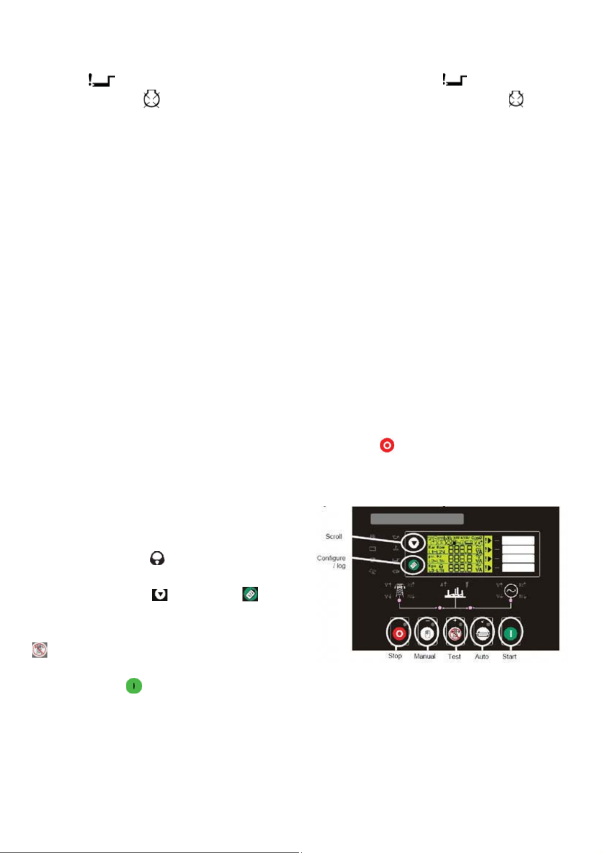
Should this sequence continue beyond the set number
starter motor is disengaged continue beyond the set
of attempts, the star t sequence will be terminated and
fail to start fault will be displayed accompanied
by a flashing shutdown symbol.
When the engine fires, the starter motor disengaged
and locked out at a pre-set frequency from the Alternator
output. Rising oil pressure can also be used to disconnect
the starter motor, however it canot be used for under
speed or over speed detection.
After the starter motor has disengaged, the Safety On
timer is acivated, allowing Oil Pressure, High Engine
Temperature, Under-speed, Charge Fail and any delayed
Auxiliary fault inputs to stabilise without triggering the
fault.
If an auxiliary output has been selected to give a load
transfer signal, this would then activate.
On the return of the mains supply, (or removal of the
Remote Start signal if the set was started by remote
number of attempts, the start sequence will be
terminated and fail to start fault will be displayed
accompanied by a flashing shutdown indicator
When the engine fires, the starter motor disengaged
and locked out at a pre-set frequency from the Alternator
output. Rising oil pressure can also be used to disconnect
the starter motor, however it canot be used for under
speed or over speed detection.
After the starter motor has disengaged, the Safety On
timer is activated, allowing Oil Pressure, High Engine
Temperature, Under-speed, Charge Fail and any delayed
Auxiliary fault inputs to stabilise without triggering the
fault.
The generator will continue to run on load regardless
of the state of the mains supply or remote start input
until the Auto mode is selected.
If Auto mode is selected, and the mains supply is healthy
signal), the Stop delay timer is initiated, once it has timed
out, the load Transfer signal is de-energised, removing
the load. The Cooling timer expires the Fuel Solenoid
is de-energised, bringing the generator to a stop.
Should the mains supply fail outside limits again during
the cooling down period, the generating set will return
to a on load condition.
Test Operation
NOTE: If a digital input configured to panel lock is active,
the LCD will display the icon. When in panel lock,
changing modules will not be possible.
Viewing the instruments and event logs is not
affected by panel lock.
To initiate a start sequence in Test, press the
pushbutton. When the controller is in the test mode
with the remote start on load signal not active, then
the Remote Stop Delay Timer begins, after which the
load is disconnected. The generator will then run off
load allowing the engine a cooling down period.
Selecting Stop de-energises the fuel solenoid, bringing
the generator to a stop.
(indicated by an LED indicator beside the button),
pressing the Start button will initiate the start
sequence.
Note: There is no Start Delay in this mode of operation.
The Fuel Solenoid is energized then the Starter Motor
is engaged.
The engine is cranked for a preset time period. If the
engine fails to fire during this cranking attempt then the
Figure 15.2. Description of Controls on DSE
5220 module
29
Page 33
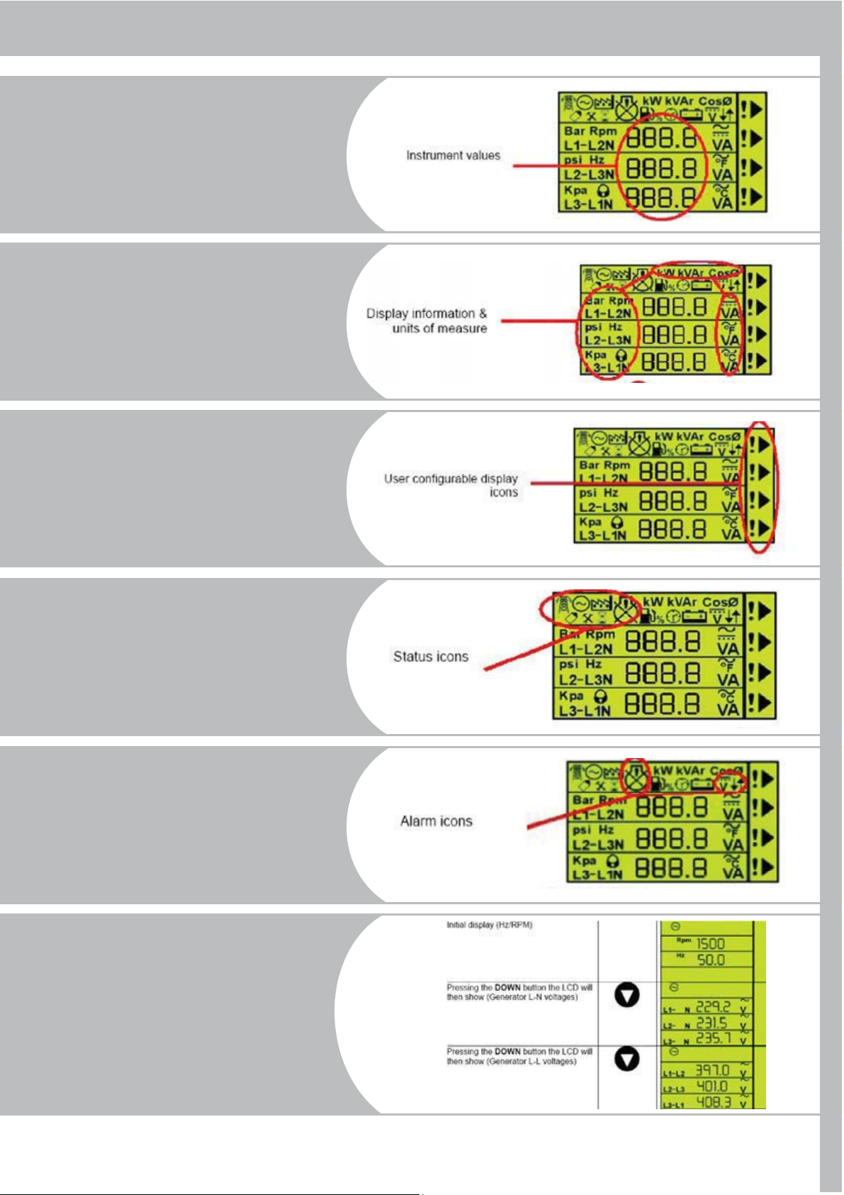
15.2.2 LCD Display Areas
Instruments
Values
Display
information
units of measure
User
Configurable
icons
Status icons
Alarm icons
Manually
Selecting
an Instruments
30
Page 34
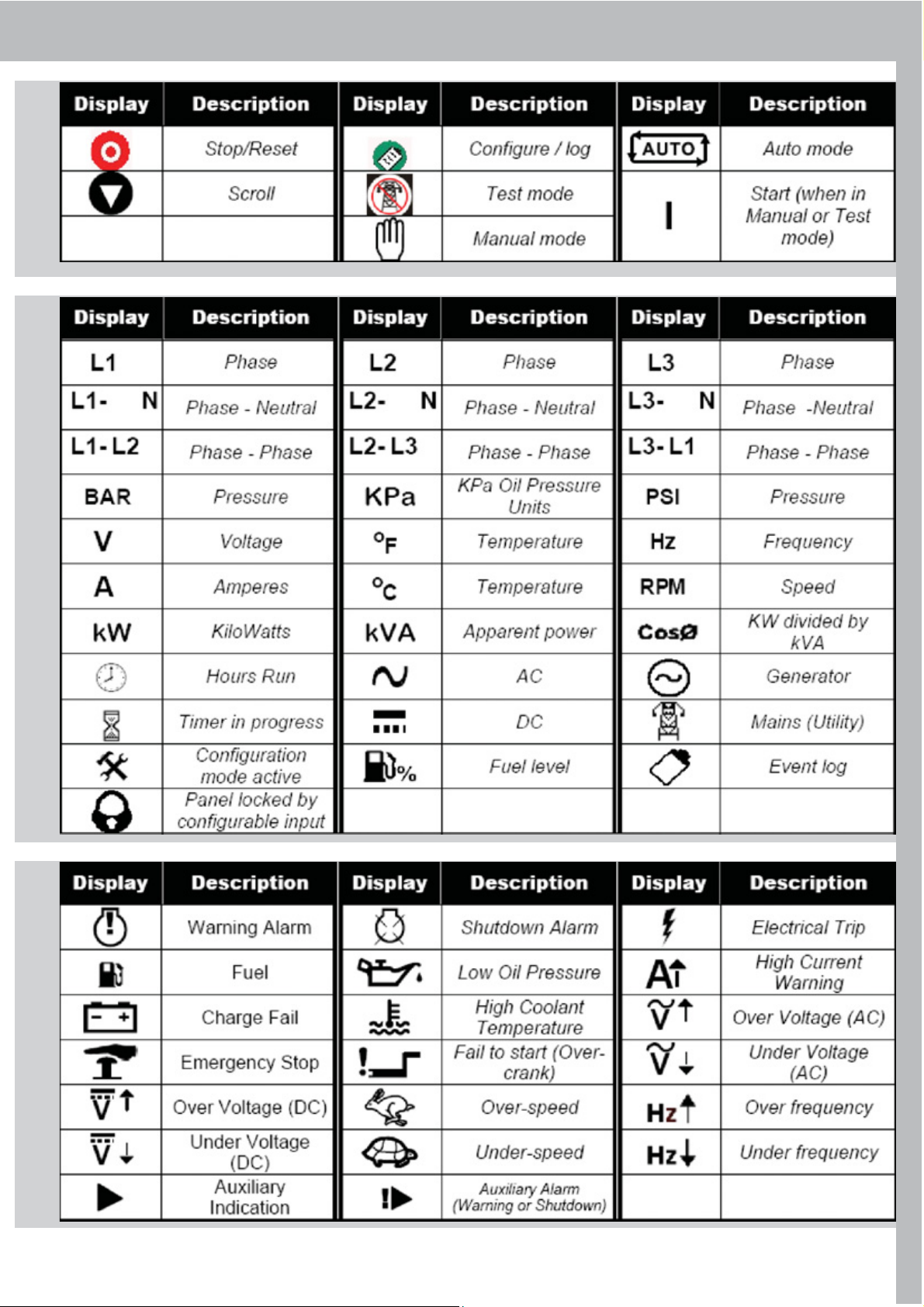
15.3. ICONS and LCD IDENTIFICATION
15.3.1. Push Buttons15.3.2. Status / Measurement Units
15.3.3. Alarm Indications
31
Page 35
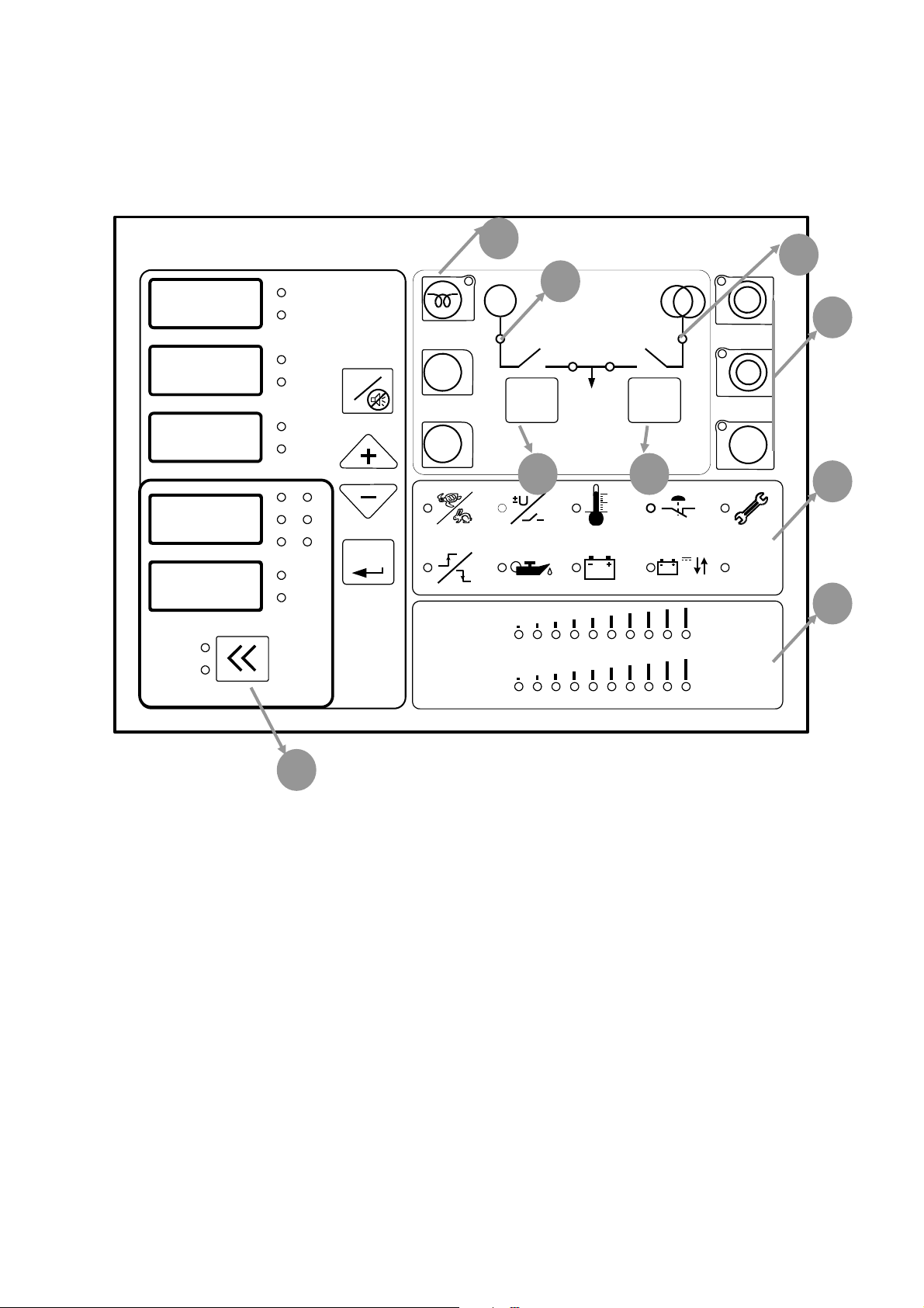
AMF 4.0 AUTOMATIC MAINS FAILURE UNIT
,
Esc
9
7
6
8
2
3
4
1
5
USER MANUAL
(AMF 4.0)
AMF 4.0
MAINS
GEN
I
R
Oil press
I
S
Temp
I
T
Battery
V
V
R
V
V
S
V
V
T
Engine
hour
Freq
Automatic Mains Failure
G
START
I / 0 I / 0
STOP
OFF
RS
ST
TR
MENU
V
122 0 F
Critical
Level
TEMPERATURE LEVEL
OIL LEVEL
100
212
Max.
Level
0
C50 0 C
0
F
A
TEST
AUX.
DESCRIPTION
AMF 4.0 genset control unit provides the functions, required in automatic mains failure applications
of gensets. It can be operated in automatic, test and manual modes. It contains digital displays
providing functions of all analog displays needed in generator panels. Device digital displays show 3
phase mains and generator voltages, 3 phase generator currents, main sand generator frequencies,
battery voltage, oil pressure (bar), engine temperature and engine hour. Generator is monitored
constantly and when generator or mains values exceed the limits adjusted in the parameter menu,
necessary actions are taken and alarm is activated. Last ten alarms are recorded in the device
memory. All operating modes and timings can be adjusted in the parameter menu. This flexibility is
provided for different kinds of generator applications.
FUNCTIONS
• Manual engine starting and stopping
• Mains monitoring, automatic start, stop and transfer switch functions
• True RMS voltage and current measurements
• Failures monitoring
• Preheating
Page 36

• Manuel, automatic and test modes
• Cost effective digital measurement displays
• Recording of last 10 failure
• Engine hour measurement and periodic service time warning
• Manuel and automatic control of mains and generator contactors
• Analog engine temperature and oil pressure measurement capability
• Adjustable operating modes and timings via parameter menu
• Analog bar graph, engine temperature and oil pressure displays
• Adjustable measurement calibrations
• Remote Start
INPUT / OUTPUTS ALARMS
• 3 phase mains and generator voltage inputs • Engine start/stop failure
• 3 phase generator current inputs • Under/over speed failure
• 12 or 24 V battery supply input • Under/over speed failure
• Oil pressure and temperature analog inputs • Under/over voltage failure
• Charge alternator input • Over current failure
• Cranking relay output • High temperature failure
• Preheat relay output • Charge fails warning
• Fuel solenoid relay output • Low oil pressure failure
• Mains contactor relay output • Periodic service time warning
• Generator contactor relay output • Periodic service time warning
• Alarm relay output • Auxiliary failure
• 2 programmable auxiliary relay output
• 2 programmable auxiliary input
PreHeat Button (1): When genset doesn’t start in cold weathers, engine can be preheated with
this button. Button function can be set as “button must be held down to preheat” or
“Preset preheats time when you press button”. Preheat button can be used in manual mode and
when engine is not running.
Start Button: This button is used to start genset . Panel will stop cranking when it detects engine
running signals. Button function can be set as “button must be held down to crank” or“preset
cranking time when you press button”. Start button can be used in manual mode and when engine
is not running. Panel will display “Str” message during cranking.
Stop Button: This button is used to stop the genset. When you pressed this button first time
panel switched to manual mode and if generator contactor is used before, genset is switched to
cooling mode. If you pressed second time genset stops immediately. Second function of this button
when you press more than 3 seconds panel will switch to off mode.
Generator Contactor (2): This button is used to transfer load to genset. When genset is
running this button can be used. Led lamp above the button shows contactor status. When the led
lamp is lit, contactor is closed. Generator contactor cannot be closed when the mains contactor is
closed. To close generator contactor, you must open the mains contactor first. In engine running
condition, when you press stop button, generator contactor will open immediately.
9
Page 37

Mains Contactor (3): This button is used to control mains contactor. It cannot be closed if
generator contactor is closed.
Generator Status Led Lamp (4):
• It is off, if engine isn’t running.
• It is on, if engine is running
• It is blinking, if genset is in engine stabilization, cooling or stopping. These topics will be explained
later
Mains Status Led Lamp (5):
• It is off, if mains voltage is outside the limits of preset values.
• It is on, if mains voltage is inside the limits of preset values.
• It is blinking in transition times (mains failure delay and mains return delay) if mains change the
state from normal to failure or failure to normal state
Alarm Led Lamps (6): From the upper left corner, high and low generator speeds, high and low
generator voltage, high coolant temperature, over current and service alarms. From lower left
corner start and stop failure, low oil pressure, charge failure, battery voltage failure and auxiliary
alarms. Detailed description will be given in the following chapters.
Oil Pressure and Coolant Temperature bar graphs (7): Analog oil pressure and coolant
temperatures can be seen in bar graphs. In temperature bar graph temperature can be seen from
50° C/ 112 °F to 100 °C/212 °F. In oil press bar graph, oil press can be seen from oil pressure
failure level to maximum oil press sender level. Display Leds: These leds are in the right side of
numerical displays. Leds indicates meaning of the value in the displays. Values in the displays can be
changed by up, down and menu buttons.
Measuring Mode Button (8): The button selects the displayed values at lower 2 numerical
display. These displays can show generator voltage and frequency or mains voltage and frequency.
Esc Button: This button has multiple tasks. These are listed below,
• In alarm condition, first press stops the horn and second press clears the alarm.
• It is used to exit parameter menu. For this process button must be held down 3 seconds.
• In the process of changing parameter when you enter invalid values you can cancel by this button.
Menu Button (Enter): This button has multiple tasks. These are listed below
• It is used to select the values in the numerical displays. When you press first time led will be lit on
the right of the display that is in selection mode. If you press up and down buttons before stop
blinking you can change the value shown in display. If the display that is wanted to change mode is
different you can press menu button and change the display in selection mode.
• If you press this button 3 seconds, you will enter the parameter menu. In parameter menu you
can use menu button to change selected parameter. You can change the active digit. After all active
digits are set last press will write value to parameter memory. Detailed information will be given in
parameters section.
Up, Down Buttons (+, -): This button has two tasks. These are listed below.
• It is used to select the values in the numerical displays. When you press first time led will be lit on
the right of the display that is in selection mode. If you press second time you can change the value
of display that is in selection mode.
Page 38

• In parameter menu you can press menu button to change selected parameter. You can change the
number of active digit.
Running Mode Buttons (9): These are manual (hand mark), automatic (A letter) and test
buttons. These buttons set running mode of genset. There is mode indication leds near each of
these buttons. When panel is in off mode you can press these buttons to wake up panel and genset
will run in selected mode.
RUNNING MODES
Automatic Mode: If you press automatic button marked “A” genset will switch to automatic
mode. In this mode panel controls mains voltages and if mains is outside the limits that you
programmed, Panel will open the mains contactor and starts the genset. After “engine stabilization
time” and “generator contactor delay” load transferred to the generator. Panel controls all the
engine values to detect possible failures after engine stabilization time. If mains come to normal
condition, mains are controlled during “mains return delay” for stabilization. If mains are normal
“after mains return delay”, generator contactor opens and mains contactor closes. Genset is
stopped after cooling period. In automatic mode, if panel is in engine off state and detects an engine
running signal. Panel will stop the engine.
Test Mode: If you press test button at the right side of front panel. Genset will be switched to test
mode. In test mode engine starts immediately. After “engine stabilization time” if parameter”test
mode” is test off load genset waits for mains failure in running condition. When mains failure occur
mains contactor opens and generator contactor closes. In same way when mains returns, panel
waits”mains return delay” and switch back to mains. If parameter“test mode” is test on load. After
engine starting, generator contactor closes and genset supply the load. If operator wants to stop
the engine in test mode panel must be returned to automatic or manual mode. In manual mode you
can stop the engine by stop button.
Manual Mode: If you press the manual button genset will be switched to manual mode. In manual
mode all start stop and preheat operations, contactor control fulfilled by panel buttons.
PANEL RUNNING PHASES
1. Generator is still: In this condition engine running signals must be absent. These are oil
pressure, charging alternator warning lamp signal, generator voltage and frequency. In manual mode
panel doesn’t react to this signal but in automatic mode panel will try to stop engine. If electricity
panel of genset has manual control and these are wanted to beused. Electronic panel must be
switched to manual mode.
2. PreHeating: In cold weathers preheating of engine can be necessary. Engine must be still during
preheating. If parameter “preheating time” is not zero, preheating is accomplished before starting
process by panel.
3. Cranking: In this stage engine is cranking. All engine signals must be absent and engine must be
still before cranking. If one of the engine signal is detected before cranking, panel switch to start and
stop alarm. Panel will show which signal is detected with engine start stop alarm. If oil pressure
signal is detected before cranking panel will wait for it to decrease to zero. If “before cranking oil
pressure delay” is elapsed and oil pressure is not zero panel will switch to start and stop alarm. In
Page 39

cranking stage all engine signals, alternator frequency, alternator voltage, charge alternator voltage
and oil pressure is controlled. If one of the signals is detected, Panel detects engine is running, crank
disconnects and switch to engine stabilization time. Generator status led starts to blink. During
cranking, “Str” message is shown in the display. Oil pressure can rise before engine running so
when oil pressure is detected, crank disconnected after “crank“disconnect oil pressure delay”.
4. Stabilization: After generator running signals detected panel waits for engine signals to
stabilize. After engine stabilization time, all alarms are activated.
5. Running: After stabilization time genset is in running condition. If genset in manual and test
modes, alternator contactor time is waited and alternator contactor is closed. In manual mode
operator can close the generator contactor by generator contactor button. In running mode
generator status led is lit.
6. Cooling: If a stop condition occurs by operator or mains status. Generator is switched to
cooling period and engine is cooled during “cooling time”. During this time engine status led is
blinking. If alternator contactor hasn’t been closed since last start cooling period is bypassed. If
mains failure occurs during cooling process generator is switched back to running mode and
alternator contactor is closed. After cooling process generator is switched to stopping condition.
7. Stopping: After cooling stage, generator switches to stopping stage. If fueling system is
operating solenoid, operating solenoid is de-energized. If fueling system is stop solenoid selenid
energizes until engine stops. If one of the engine running signals is detected stopping period doesn’t
ends. Alternator frequency and voltage, charge alternator warning lamp signal and oil pressure must
be absent. If panel detects engine signals after “fail to stop delay” panel will switch to start stop
alarm.
8. Generator shutdown: Generator is stopped because of a red alarm. Generator cannot be
started if alarm is not cleared.
ALARMS
Alarms are divided to red and yellow alarms. Yellow alarms are for warning purposes and
don’t stop the generator. Red alarms are serious and if occur generator contactor is opened
and generator is stopped immediately.
High and low speed (RED ALARM): If alternator frequency is higher than “generator over
frequency failure” or is lower than “generator under frequency failure” “ panel switches to this
alarm. Alarm is activated after “generator frequency failure delay”.
High and low alternator voltage (RED ALARM): If alternator voltage is higher than
“generator over voltage failure” or is lower than “generator under voltage failure” “ panel switches
to this alarm. Alarm is activated after “generator voltage failure delay”
High coolant temperature (RED ALARM): If temperature that is read from temperature
sender is higher than “high coolant temperature level” or if temperature switch sends alarm to
panel. Panel switches to high coolant temperature alarm.
Over current failure (RED ALARM): If currents values read from current transformers is
higher than “over current level”. Generator contactor is opened and generator switches to cooling.
After cooling stage generator stops. Alarm is activated if condition continues for “over current
Page 40

alarm delay”
Periodic service: When periodic service time elapsed after last periodic service. Alarm is
displayed. Only service personnel can reset alarm.
Fail to start stop: If this alarm occurs that means panel couldn’t start or stop engine. All engine
signals must be absent and engine must be still before cranking. If one of the engine signals is
detected, before cranking, panel switch to start and stop alarm. Panel will show which signal is
detected with engine start stop alarm. If oil pressure signal is detected before cranking panel will
wait for it to decrease to zero. If “before cranking oil pressure delay” is elapsed and oil pressure is
not zero panel will switch to start and stop alarm. In automatic and test modes if generator couldn’t
be started after user defined crank attempts, panel switches to fail to start stop alarm. In engine
stopping stage if panel still detects engine signals after “fail to stop delay”. Panel switches to fail to
start stop alarm. Alarm led lamps indicates which engine signal is still present and causes fail to start
stop alarm.
Low oil pressure (RED ALARM): If oil pressure that is read from oil pressure sender is lower
than “low oil pressure level” or if oil pressure switch sends alarm to panel. Panel switches to low oil
pressure alarm.
Charge Failure (YELLOW ALARM): If charge voltage read from charge alternator warning
lamb terminal decreases, panel switches to this alarm. This alarm doesn’t stop generator.
Battery high and low voltage (YELLOW ALARM): If battery voltage is higher than “battery
high alarm level” or is lower than “battery low alarm level” panel switches to this alarm. This alarm
doesn’t stops engine.
AUX. Auxiliary input (YELLOW or RED ALARM): When an auxiliary input alarm occur. This
led is lit and A1, A2, A3 or A4 message is written to display. A1 means auxiliary input1 alarm.
Mains failure: If mains voltage is lower than “mains under voltage failure” or is higher than “mains
over voltage failure” mains failure occur and in automatic
mode generator is started. If mains comes to normal condition (higher than “under voltage return”
and lower than “over voltage return”) generator is stopped in automatic condition.
Emergency stop: If auxiliary input is adjusted for emergency stop and user presses emergency
stop button. “StP” message is shown in the display, generator contactor opens and engine stops
immediately. To clear this alarm user must pull emergency stop button and clear the alarm.
Sensor failure: If cable connected to sender terminal of oil pressure and temperature senders
breaks. Sensor failure alarm is given. For oil pressure sender “oSn” message and for coolant
temperature sender “tSn” message is shown in the display. Alarm is activated if condition continues
for 4 seconds. If “analog oil pressure sender usage” and “analog coolant temperature sender usage”
parameters are set to 0, sender will be used for display purposes and no alarm is given in sensor
failure condition.
EEProm Failure: When this alarm occurs “EEP” message is written to display and you must call
service. Genset mustn’t be started.
Page 41

16. GENERAL PRECAUTIONS AND CONTROLS
17.1. Control System P 300 Panel Specifications
WHICH MUST BE DONE AFTER STARTING UP THE
GENERATING SET
Check for any abnormal noise or vibration on the
generating set.
Check if the exhaust system has any leakage.
Monitor the generating set operation by means of
the control module LCD display. Check the
engine temperature and oil pressure
Oil pressure must reach the normal value 10
seconds after the generating set operation.
Monitor the generating set outlet voltage and
frequency by means of the control module LCD display.
Check the voltage, if the voltage between
phases is 400 V. and between phase and neutral is
230 V. Check that the frequency is 51 - 52 Hz on
generating sets with mechanical governors and 50
Hz on generating sets with electronic governors.
If an engine block water heater is not available, run
the generating set at no-load for 8 minutes and when
the engine warm than apply on load (for manual
models)
Apply load to the generating set as follows:
Set the alternator outlet circuit breaker on the panel
to ON position.
Set the load circuit beakers (or fuses) on the
distribution panel to ON position one by one. This
way, the generating set cannot be suddenly put
under full load. Otherwise, the engine stalling or
alternator winding insulation of formation or burning
can occur.
Set the alternator outlet circuit breaker on the circuit
to OFF position before stop the generating set.
Continue to run the unloaded engine for purpose of
cooling period for 5 minutes and then stop.
Never operate the generating set before removing
any fault, if any.
17. CONTROL PANELS
Control, supervision and protection panels are mounted
on the generator base frame.
Equipments:
- DSE 720, Automatic Mains Failure module
- Static battery charger
- Emergency stop push button
DSE 720 Module Features
- To monitoring AC mains supply
- Automatic controls generating set, start and stop
- Provide signal to change over switch
- Scrolling digital LCD display
- Front panel configuration of timers and alarm trip
points
- Easy push button control
STOP/RESET - MANUAL - AUTO - TEST - START
Metering via LCD display
- Generator Volt (L - N)
- Generator Ampere (L1, L2, L3)
- Generator Frequency (Hz)
- Mains Volt (L - L / L - N)
- Engine cooling temperature
- Engine oil pressure
- Engine speed
- Engine hours run
- Engine battery volt
Alarms
Over current
Over speed
Under / Over mains volt
Under / Over mains frequency
Low oil pressure
High engine temperature
Low battery volt
Charge fail
Start failure
Emergency stop
LED indication
Mains available
Mains on load
Generator available
Generator on load
32
Page 42
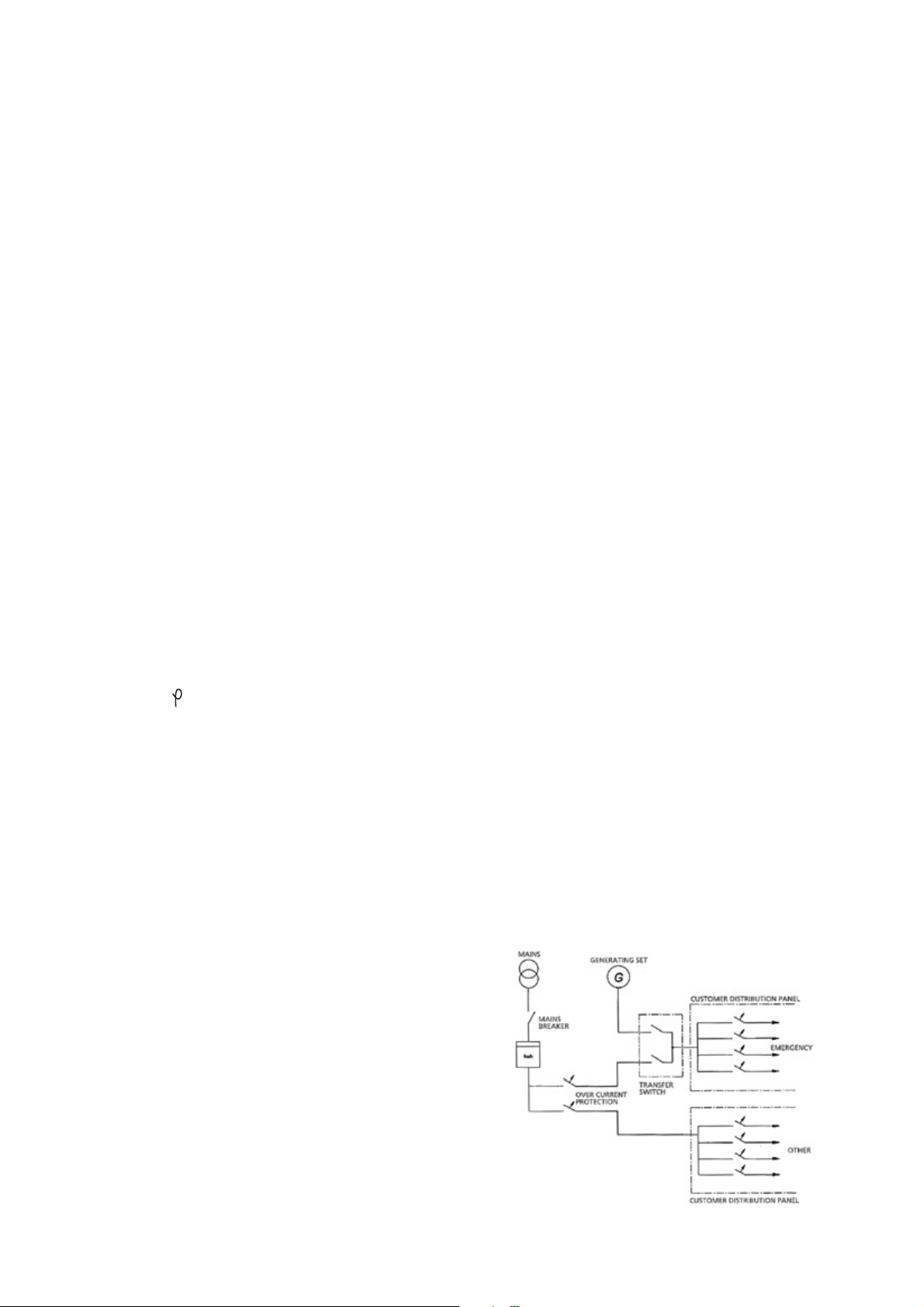
17.2. Control System P 5220
Equipments:
- DSE 5220, Automatic Mains Failure module
- Static battery charger
- Emergency stop push button
DSE 5220 Module Features
- To monitoring AC mains supply
- Automatic controls generating set, start and stop
- Provide signal to change over switch
- Scrolling digital LCD display
- Remote communication via RS232 port or RS 485
mod bus output.
- Event logging of shutdown alarms.
- Front panel configuration of timers and alarm trip
points
- Easy push button control
STOP/RESET - MANUAL - AUTO - TEST - START
Metering via LCD display
- Generator Volts (L-L / L - N)
- Generator Ampere (L1, L2, L3)
- Generator Frequency (Hz)
- Generator kVA
- Generator kW
- Generator Cos
- Mains Volt (L - L / L - N)
- Mains Frequency (Hz)
- Engine cooling temperature (
o
C & oF)
- Engine oil pressure (PSI & Bar)
- Engine speed (RPM)
- Engine hours run
- Plant battery volt
Multiple Alarms
Under / Over generator volts; Pre-alarm and
Shutdown
Under / Over generator frequency Pre-alarm and
Shutdown
Under / Over mains volts
Under / Over mains frequency
Over current; Shutdown
Low oil pressure; Pre-alarm and Shutdown
High engine temperature; Pre-alarm and Shutdown
Under/over speed; Shutdown
Low coolant level; Shutdown
Fail to start; Shutdown
Fail to stop; Warning
Low/High battery volts; Warning
Charge fail; Warning
Emergency stop; Shutdown
Can Data Fail; Shutdown
Can ECU Fail; Pre-Alarm and Shutdown
The Event Log
5220 control module maintains a log the last 15 shutdown
alarms to enable the operator or engineer to view the
past alarms history.
18. THE PLACEMENT AND INTALLATION OF
TRANSFER SWITCH
The placement of the transfer switch and its mountings:
Position the transfer switch near the emergency
power panel.
Locate the transfer switch in a place where it is
clean, not over- heated, and having a good
ventilation. If the environment temperature is above
o
40
C, breakers will open more easily. There must be
enough working place around the transfer switch.
Having breaker between the generating
set and the transfer switch is optional.Current from the
generating set must be distributed equally to the three
phase if possible.
Current from one phase should not exceed the
nominal current.
If the transfer switch panel is apart from the
generating set, transfer switch must be placed as
close possible to the distributor panel.
In this case power cables are drawn from generating
set, mains panel and emergency power panel.
Furthermore 8x2,5 mm2 control cable must be drawn
from the generating set control panel.
15.3.3. Typical emergency power system installation
33
Page 43

19. ENGINE TROUBLESHOOTING
The starter motor turns the engine too slowly:
Battery capacity to low
Bad electrical connection
Faulty in starter motor
Wrong grade of lubricating oil
The engine does not start or difficult to start:
Starter motor turns engine too slowly
Fuel tank empty
Faulty in fuel control solenoid
Restriction in a fuel pipe
Faulty in fuel lift pump
Dirty fuel filter element
Air in fuel system
Faulty in atomisers
Colt start systems used incorrectly
Fault in cold start system
Restriction in fuel tank vent
Wrong type or grade of fuel used
Restriction in exhaust pipe
Not enough power:
Restriction in a fuel pipe
Faulty in fuel lift pump
Dirty fuel filter element
Air in fuel system
Restriction air filter/cleaner or induction system
Restriction in exhaust pipe
Fault in atomisers or atomisers of an incorrect type
Restriction in fuel tank vent
Wrong type or grade of fuel used
Restricted movement of engine speed control
Engine temperature is too high or low
Misfire
Restriction in a fuel pipe
Faulty in fuel lift pump
Dirty fuel filter element
Air in fuel system
Fault in atomisers or atomisers of an incorrect type
Fault in cold start system
Engine temperature is too high
Incorrect valve tip clearances
The pressure of the lubrication oil is too low:
Wrong grade of lubrication
Not enough lubrication oil in sump
Defective gauge
Dirty lubrication oil filter element
High fuel consumption:
Restriction air filter/cleaner or induction system
Fault in atomisers or atomisers of an incorrect type
Fault in cold start system
Wrong type or grade of fuel used
Restricted movement of engine speed control
Restriction in exhaust pipe
Engine temperature is too low
Incorrect valve tip clearances
Black exhaust smoke:
Restriction air filter/cleaner or induction system
Fault in atomisers or atomisers of an incorrect type
Fault in cold start system
Wrong type or grade of fuel used
Restriction in exhaust pipe
Engine temperature is too low
In correct valve tip clearances
Engine over load
Blue or white exhaust smoke
Wrong grade of lubrication
Fault in cold start system
Engine temperature is too low
The engine knocks:
Faulty in fuel lift pump
Fault in atomisers or atomisers of an incorrect type
Wrong type or grade of fuel used
Fault in cold start system
Engine temperature is too high
In correct valve tip clearances
The engine runs erratically:
Fault in fuel control
Restriction in a fuel system
Faulty in fuel lift pump
34
Page 44

Dirty fuel filter element
Restriction air filter/cleaner or induction system
Air in fuel system
Fault in atomisers or atomisers of an incorrect type
Fault in cold start system
Restriction in fuel tank vent
Restricted movement of engine speed control
Engine temperature is too high
In correct valve tip clearances
Vibration
Fault in atomisers or atomisers of an incorrect type
Restricted movement of engine speed control
Engine temperature is too high
Fan damaged
Faulty in engine mounting or flywheel housing
The engine temperature is too high:
Restriction air filter/cleaner or induction system
Fault in atomisers or atomisers of an incorrect type
Fault in cold start system
Restriction in exhaust pipe
Fan damaged
Too much lubrication oil in sump
Restriction in air or water passage of radiator
Insufficient coolant system
20. GENERATİNG SET MAINTENANCE
A good maintenance program is the key to long
generating set life. Maintenance and service should only
be carried out by qualified technicians. The maintenance
and service which are done must be recorded to the
Maintenance Record Form. In general, the generating
set should be kept clean. Do not permit liquids such as
fuel or oil film to accumulate on any internal or external
surfaces. Wipe down surfaces using an aqueous industrial
cleaner.
20.1. Maintenance Schedule for Generator Sets
A. Daily or every 20 hours
Check
Visually inspect engine, generator, transfer switch and
control panel.
For, Oil, Water and Fuel leaks.
For, Coolant level, Oil level, Fuel level
Battery charge level
Operation of coolant heater
Drain Fuel/Water separator
Inspect the engine fan blades
Inspect the drive belt
B. Weekly
Repeat Daily
Crankcase pressure:
Restriction in breather pipe
Vacuum pipe leaks or fault in exhauster
Bad compression:
Restriction air filter/cleaner or induction system
Incorrect valve tip clearances
The engine starts and stops:
Dirty fuel filter element
Restriction air filter/cleaner or induction system
Air in fuel system
The engine shuts down after approximately 15 seconds:
Bad connection towards oil pressure switch/coolant
temperature switch
Check
Fuel System
Fuel level in main tank
Day tank float switch
Fuel transfer pump operation
Fuel lines and connections
Cooling System
Adequate fresh air to engine
Hose and connections
Battery charging alternator belts
Lubricating System
Oil level (Governor Housing)
Exhaust System
Exhaust leaks
Tighten connections
Output voltage and frequency
35
Page 45

Transfer Switch
Operation under load
No unusual sounds
Terminals and connections normal colour
Doors closed securely
C. 6 Months or 200 Hours
Repeat Weekly
Lubricating System
Change lubricating oil
Change lubricating oil filters
Clean crankcase breather
Fuel System
Change fuel filters
Drain sediment from main tank
Governor
Change lubricating oil
Cooling System
Check antifreeze
Change water filter
Inspect
Magnetic pick-up and adjust
Circuit breakers and fuse holders
Generator
Measure/record generator winding resistance
with Megger
Perform full load test at Nameplate kW
D. 24 Months or 2,000 Hours
Check
Turbocharger bearing clearance
Exhaust restriction
The valves settings
The injectors settings
Vibration damper
Change
Coolant and antifreeze and flush system
Clean
Turbocharger compressor wheel and diffuser.
Engine safety controls
Check operating alarms and safeties
C. 12 Months or 800 Hours
Repeat Maintenance “C”
Check the valves setting
Fuel System
Analyze/replace diesel fuel
Cooling System
Clean exterior of radiators
Check coolant treatment
Check anti-freeze solution
Check water pumps and circulating pumps
Examine duck work
Clean/check motor operated louvers
Intake System
Check air cleaner element and change at 635
mm H2O
Clean
The engine
Generator rotor and stator with compressed air
36
Page 46

GENERAL PRECAUTIONS ABOUT WARRANTY
DEAR AKSA GENERATING SET OPERATOR,
PLEASE TAKE CARE TO THE FOLLOWING IN ORDER TO PREVENT THE GENERATING SET WARRANTY TO BECOME INVALID BEFORE
THE TERMINATION OF THE WARRANTY PERIOD AND TO ENSURE TROUBLE-FREE OPERATION OF THE GENERATING SET WITH A
LONG LIFE!
o MAINTENANCE AND REPAIR WORKS WILL NOT BE COVERED BY THE WARRANTY UNLESS THE WARRANTY CERTIFICATE, INVOICE OR DELIVERY
CERTIFICATE OF THE GENERATING SET IS SUBMITTED.
o THE WARRANTY OF THE GENERATING SET WILL BECOME INVALID IN CASE OF ANY INTERVENTION OF ANY PERSON OTHER THAN
AUTHORIZED AKSA SERVICES OR BY PRIOR WRITTEN APPROVAL FROM AKSA POWER GENERATION ON THE GENERATING SET FOR ANY
REASON.
o CONTROLAND MAINTENANCE WORKS INDICATED IN THE PERIODICAL MAINTENANCE SCHEDULE AND THE OPERATING MANUAL MUST BE
CARRIED OUT COMPLETELY AND TIMELY THE FAILURES DUE TO INCOMPLETE OR UNTIMELY MAINTENANCE ARE NOT COVERED BY THE
WARRANTY.
o GENERATING SET SHOULD BE MOUNTED AS INDICATED IN THE OPERATING MANUAL OTHERWISE, THE PROBLEMS WHICH ARE
LIKELY TO OCCUR WILL NOT BE COVERED BY THE WARRANTY CUSTOMER IS RESPONSIBLE FOR THE FAILURES WHICH ARE LIKELY TO
OCCUR IN CASE THAT THE DIESEL OIL USED CONTAINS DIRT OR WATER.
o THE OIL TYPE INDICATED IN THE OPERATING MANUAL SHOULD BE USED IN THE ENGINE. OTHERWISE, THE FAILURES WHICH ARE
LIKELY TO OCCUR WILL NOT BE COVERED BY THE WARRANTY.
o BATTERIES WILL NOT BE COVERED BY THE WARRANTY IF THEY ARE SUBJECTED TO BREAKAGE, EXCESSIVE ACID FILL OR HARDENING BY LEAVING
UNCHARGED.
o ON MANUAL GENERATING SETS, NEVER START OR STOP THE DIESEL ENGINE WHEN THE GENERATING SET IS UNDER LOAD. ENGINE
SHOULD BE STARTED AND STOPPED AFTER LOAD IS DISCONNECTED AND THE GENERATING SET IS AT IDLE CONDITION. OTHERWISE,
THE VALVES CAN BE SEIZED, THE VOTAGE REGULATOR. TRANSFORMER AND DIODES CAN BE BROKEN DOWN. THESE CONDITIONS ARE NOT
COVERED BY THE WARRANTY.
o OUR COMPANY DOES NOT TAKE THE RESPONSIBILITY OF THE DAMAGES ON THE MAINS SUPPLY CONTACTOR OF THE AUTOMATIC
GENERATING SETS DUE TO OVERCURRENT, LOW OR HIGH VOLTAGE.
o NEVER REMOVE THE BATTERY TERMINALS VVHILE THE GENERATING SET IS IN USE. EVEN A MOMENT OF DISCONNECTION CAN CAUSE A
DAMAGE ON THE ELECTRONIC CLOSING RELAY OF THE CHARGE ALTERNATOR AND ON THE ELECTRONIC ENGINE SPEED CONTROL CIRCUIT
THESE CONDITIONS ARE NOT COVERED BY THE WARRANTY.
o FAILURES DUE TO OVERLOAD AND UNBALANCED LOAD IN EXCESS OF THE GENERATING SET POWER (SUCH AS ALTERNATOR AND
CONTACTOR FAILURES) ARE NOT COVERED BY THE WARRANTY.
o FAILURES DUE TO OVERLOAD AND UNBALANCED LOAD IN EXCESS OF THE GENERATING SET POWER (SUCH AS ALTERNATOR AND CONTACTOR
FAILURES) ARE NOT COVERED BY THE WARRANTY.
o WHEN THE MANUAL GENERATING SET IS STARTED UP, IT SHOULD BE WARMED BY OPERATING AT IDLE FOR 5 MINUTES. VVHEN STOPPING
THE DIESEL ENGINE, IT SHOULD BE UNLOADED AND THEN CONTINUED TO BE OPERATED FOR COOLING FOR 10 MINUTES BEFORE STOPPING.
OTHERWISE. PROBLEMS WHICH ARE LIKELY TO OCCUR VVILL NOT BE COVERED BY THE WARRANTY.
o WARRANTY PERIOD IS 1 YEAR BEGINNING FROM THE PURCHASE DATE.
36
Page 47
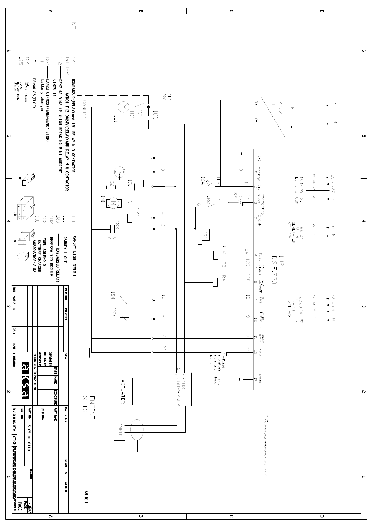
Page 48
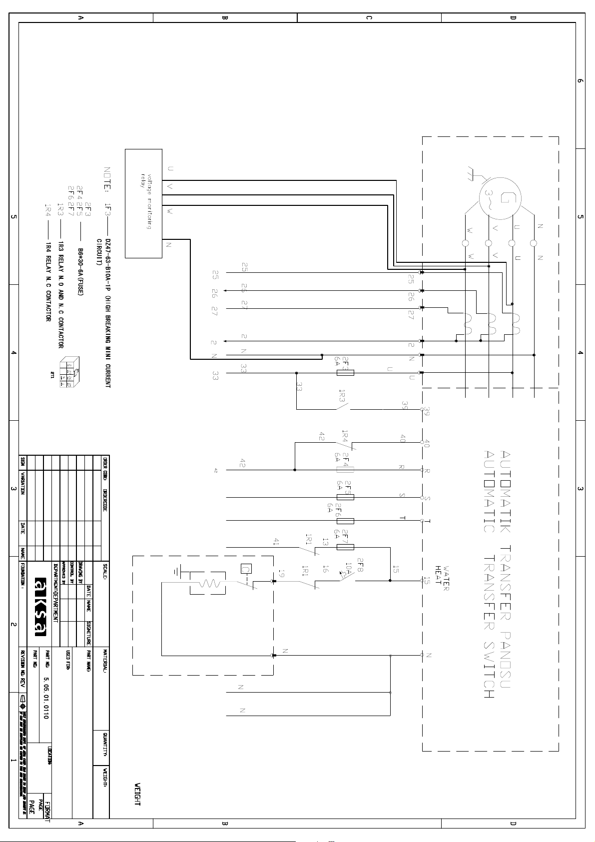
Page 49
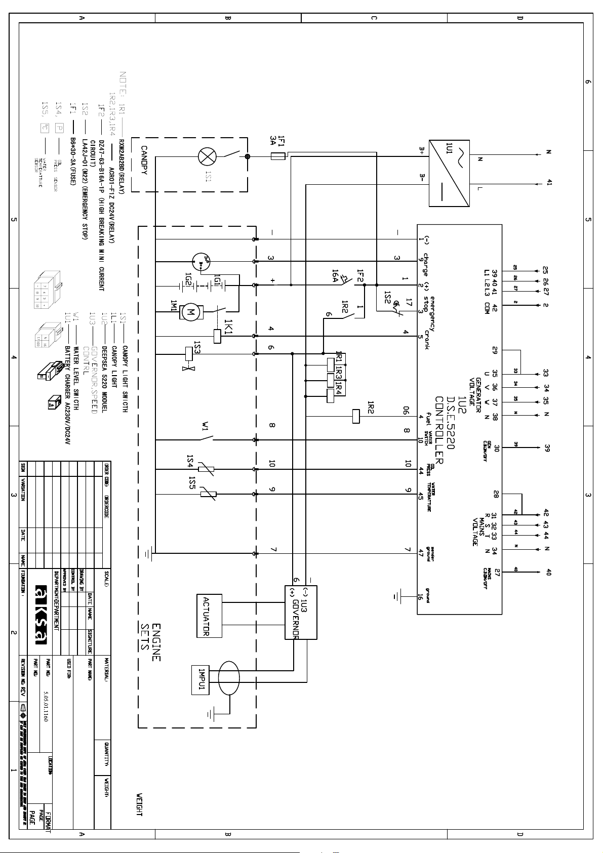
Page 50
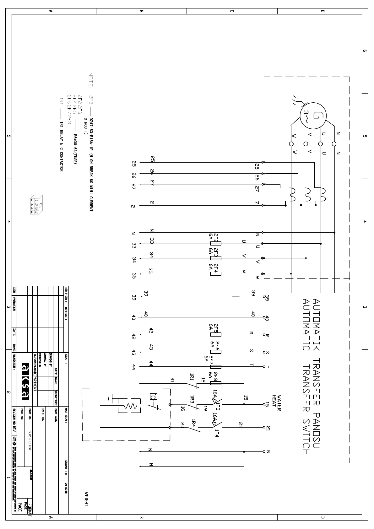
Page 51

Page 52
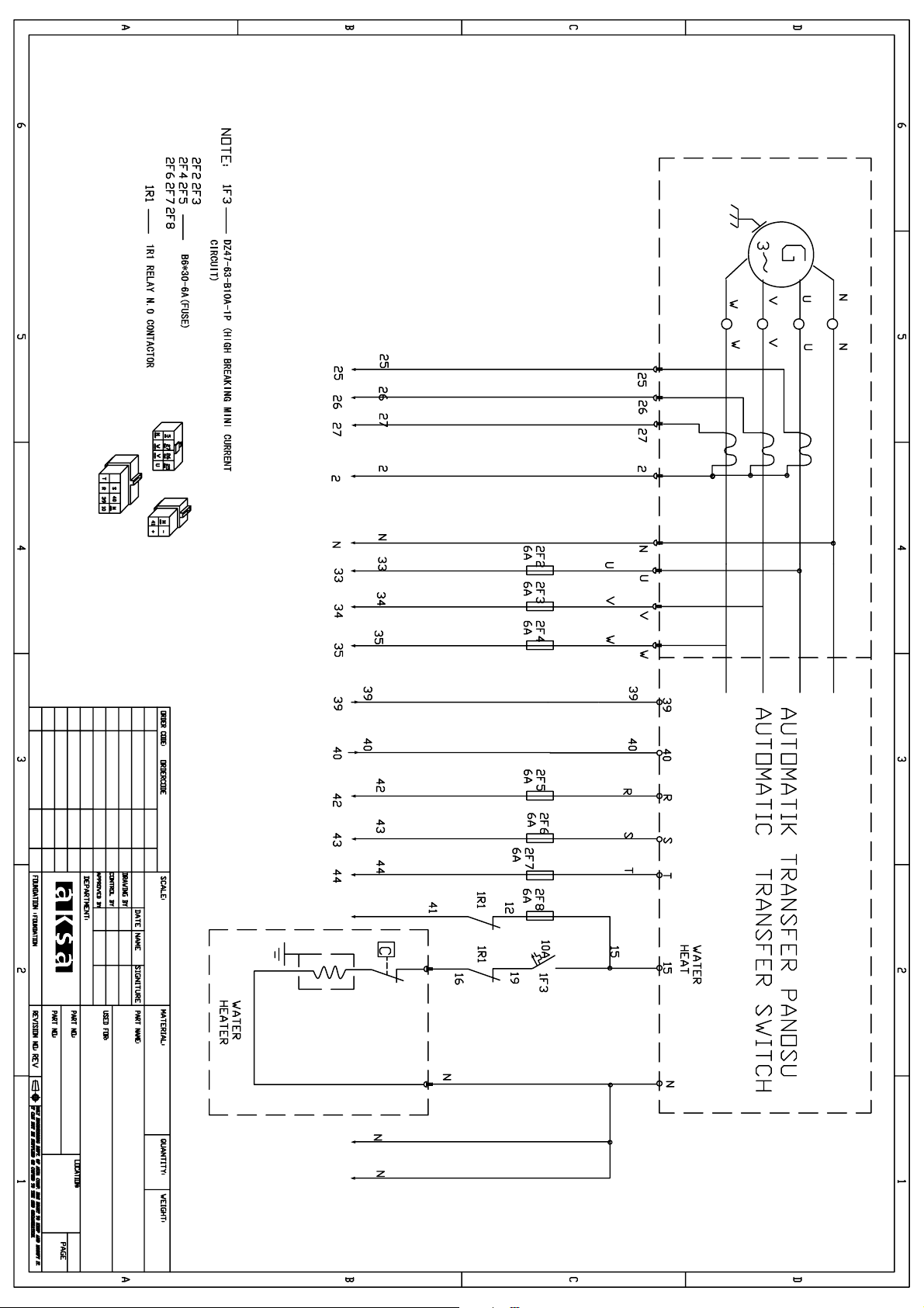
Page 53

NOTES
Page 54

NOTES
Page 55

 Loading...