

Page 1
WMS 400 Quick guide to build a channel
POWER
1
DC IN
12V 500mA
FIRST/SINGLE CHANNEL.
5
2x
7
OK
SELECT GROUP
SELECT NAME OF COUNTRY *
AT, BE, CH, D1-5, DN, U1, U2, GB, IS,
LI, LU, PT, SE
2 a2 a 2 a2 b
6
NUMBER OF
CHANNELS
1 -13x OK
8
3
4
ALTERNATIVE
ON
UNLOCK 3 SEC.
e.g. 3x
OK
9
OK
HT 400
OFF -> MUTE
10 sec. time to transmit
RETRY 2x
10
OK
>>>>> 5 11
3-9 cm
13
OK
14
OK
15
OK
ALTERNATIVE
PT 400
12
OFF -> MUTE
10 sec. time to transmit
2x
DISPLAYS SELECTED CHANNEL 1...12
NO
3-9 cm
ALTERNATIVE
>>> PERFORMANCE
* AT - AUSTRIA, BE - BELGIUM, CH - SWITZERLAND, D1-5 - GERMANY, DN - DENMARK, U1 - UHF CHANNEL SHARED, U2 - UHF CHANNEL SHARED, GB - UNITED KINGDOM, IS - ISLAND,
LI - LIECHTENSTEIN, LU - LUXEMBURG, PT - PORTUGAL, SE - SWEDEN PLEASE CHECK YOUR LOCAL DEALER TO FULFIL REGULATION NEEDS!
Page 2
NEXT/MULTI CHANNEL.
1 2
1x
SELECT CHANNEL
4 5
OK OK OK
SELECT GROUP
OF FIRST CHANNEL
6
OK
ALTERNATIVE
PT 400
7
8
OFF -> MUTE
10 sec. time to transmit
9
NO
OK
3
OK
SELECT NEXT CHANNEL 2...12
3-9 cm
HT 400
OFF -> MUTE
10 sec. time to transmit
SELECT NAME OF COUNTRY *
AT, BE, CH, D5, DN, U1, U2, GB, IS,
LI, LU, PT, SE
>>> 1
OK
3-9 cm
1 -13x
OK
RETRY 2x
ALTERNATIVE
10
OK
11
1x
DISPLAYS SELECTED CHANNEL 2...12
>>> PERFORMANCE
WMS 400 System optimize
HT GAIN. PT GAIN.
11
UNLOCK 3 SEC.
HT 400 C
3
7.. 9 10
2
3x OK
HT 400 D
4
OK
ALTERNATIVE
1x
11
OK
OK
* AT - AUSTRIA, BE - BELGIUM, CH - SWITZERLAND, D1-5 - GERMANY, DN - DENMARK, U1 - UHF CHANNEL SHARED, U2 - UHF CHANNEL SHARED, GB - UNITED KINGDOM, IS - ISLAND,
LI - LIECHTENSTEIN, LU - LUXEMBURG, PT - PORTUGAL, SE - SWEDEN PLEASE CHECK YOUR LOCAL DEALER TO FULFIL REGULATION NEEDS!
3x
Page 3

Explanation to Quick Guide Menu for
WMS400 Wireless Microphone System
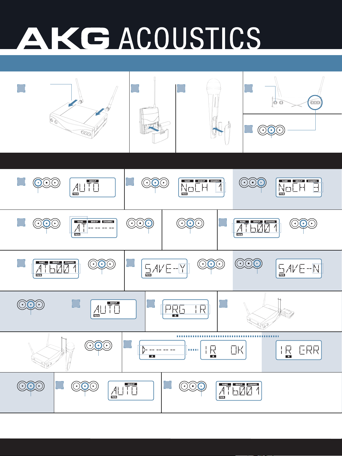
Activate SR400 power switch and unlock controls (fig. 1-4 WMS400 Quick
guide). Attach antenna and power supply to receiver and install batteries into the
transmitter(s). Once the receiver is powered on, the receiver must be switched from
LOCK mode to SETUP mode in order to change internal settings. To do so, hold
down the enter button (O) located on the right side of the receiver front panel for
about 1 1/2 seconds. The LOCK indicator will disappear from the panel display when
switched to SETUP mode. Once in SETUP mode, use the left and right arrow keys
(< or >) buttons to find the parameter you want to change. There are three set up
screens for selecting the receiving frequency (Auto Group, Auto Channel and Preset).
For single channel set up, it is recommended to use the AUTO group screen.
Select AUTO group (fig. 5, 6). Using the arrow buttons, find AUTO group. Press
the enter button briefly. Again, use the arrow keys to choose the number of channels
to be used. Press enter. The receiver will automatically find a Group with the
selected number of clean frequencies within the selected Preset and tune to the first
clean frequency. Name should now be flashing.
Select Name (fig. 7-10). The banks of internal channel presets are specific to
certain countries. The two letter abbreviation indicates the country in which the unit
is to be used. The receiver comes programmed for country code AT (Austria). Using
the arrow keys find US. Press enter. Name, Group and Channel should now be
flashing. Press enter. When prompted to save the settings (Save-Y), press enter
again or use the right arrow key to select Save-N and press enter to go back and
change settings. Once settings have been saved, the receiver will flash PROG IR.
Program IR (fig. 11-15). Note: HT400 and PT400 transmitters can not be placed in
Program IR mode from the on position. If the transmitter is already powered on,
switch it to Off, then to Mute/Prg. The infrared sensor on the SR400 receiver is
within a rectangle located on the right side of the face above the arrow keys. The IR
sensor on the HT400 handheld transmitter is located just above the LCD display and
behind the letters “IR”. The IR sensor on the PT400 is located on top of the unit next
to the antenna. At this point, the transmitter must be programmed to match the
receiver channel setting. Be sure that the battery is properly installed in the
transmitter. Switch the transmitter from the off position to the MUTE/Prg (middle)
position. Hold the transmitter so that the IR sensor is 3-4 inches from the receiver IR
sensor and briefly press the receiver enter button. If programming of the
transmitter is successful, the receiver will display IR OK. If not, the receiver display
will read IR ERR. Pressing the receiver enter button will allow for another attempt.
1
Page 4

(If the transmitter has been powered on, first, shut it off. Then, select the Mute/Prg
position.) While the RETRY prompt is flashing, position the transmitter in front of
the receiver IR sensor. Press the receiver enter button. Once the receiver displays
IR OK and the transmitter display shows pro6 IR you can lock the controls by
holding down the enter button until the lock indicator illuminates. The wireless
system is now ready for use.
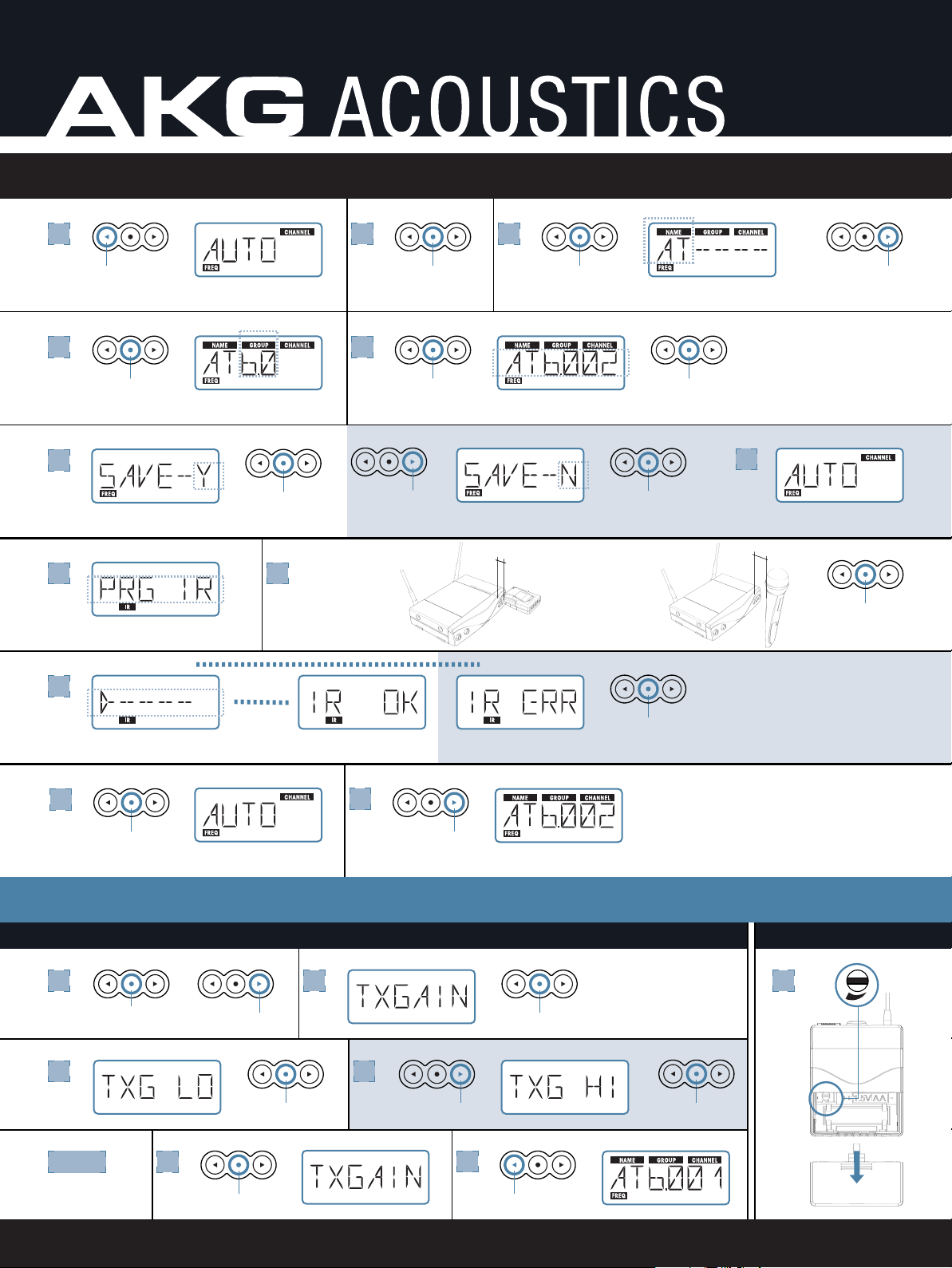
Additional Wireless Systems (fig. 1-6 NEXT/MULTI CHANNEL). Leave the
previous transmitter and receiver powered on. Power on the next SR400 receiver
and unlock the controls the same as was done on the first receiver. Press the left
arrow key one time to display the AUTO channel screen. Press the enter button
again. Name and the two letter country code will now be flashing. Use the arrow
keys to select US. Then, press enter. Group will now be flashing. Using the arrow
keys, select the same group used by the first receiver. Press enter. Select the next
channel in succession (2-12) and press enter. When prompted to save the settings
(Save-Y), press enter again or use the right arrow key to select Save-N and press
enter to go back to AUTO channel and change settings.
Program IR (fig. 7-11). Once the AUTO channel settings have been saved, PRG
IR will be displayed. Repeat the IR programming as described for the first unit.
Once programming is complete, hold down the receiver enter button until the display
is locked. Leave all previously programmed systems powered on and repeat AUTO
channel programming for subsequent wireless systems.
Optimize system performance (fig. 1-11 WMS400 System Optimize). In order to
get the maximum performance from the WMS400 wireless microphone system the
receiver must be programmed to match the gain from the various transmitter styles.
Press and hold the receiver’s enter button until the word lock is no longer visible on
the receiver LCD display. Press the right arrow button three times to display
TXGAIN. Press the enter button briefly. The display will now read TXG LO or TXG
HI. Use the left or right arrow buttons to choose the proper gain. For the HT400/C
select TXG LO. For the HT400/D select TXG HI. Either gain setting may be used
with the PT40 pocket transmitter depending on the qualities of the mic being used
with it. The PT40 also has a gain trim control located in the battery compartment.
WMS400 Quick Start Menu September 26, 2003
AKG Acoustics, U.S. – 914 Air Park Center Drive – Nashville, TN 37217
PH: 615/620-3820 FAX: 615-620-3875
www.akgusa.com
2
Page 5

TECHINCAL BULLETIN
WMS400 COUNTRY CODES
The WMS400’s system has the ability to be legally used in other
countries than the United States. In its presets of inter-modulation
free frequency groups you will find country codes. For example, the
SR400 receiver preset group screen will display “AT 1.0 01” and this
represents:
• “AT”. This represents a preset for Austria.
• GROUP is “1.0”. This represents frequency group 1 of a preset
for Austria.
• Channel is “01”. This represents channel 1 of frequency group 1
of a preset for Austria.
Set the country code to “US” for optimum operation when using the
system in the United States. Using the “US” presets will always
ensure the WMS400 system provides the maximum number of
channels used at one time with optimum frequency coordination.
AT – Austria
CH – Switzerland
DE – Germany
F1 – France 1
F2 – France 2
F3 – France 3
GB – United
Kingdom
IE – Ireland
IS – Island
IT – Italy
LI – Liechtenstein
LU – Luxemburg
NL – Netherlands
PT – Portugal
SE – Sweden
US – USA
CA – Canada
AR – Argentina
CR – Korea
J1 – Japan 1
J2 – Japan 2
WMS400 Tech Bulletin 001 September 26, 2003
AKG Acoustics, U.S. – 914 Air Park Center Drive – Nashville, TN 37217
PH: 615/620-3820 FAX: 615-620-3875
www.akgusa.com
 Loading...