


PT 81
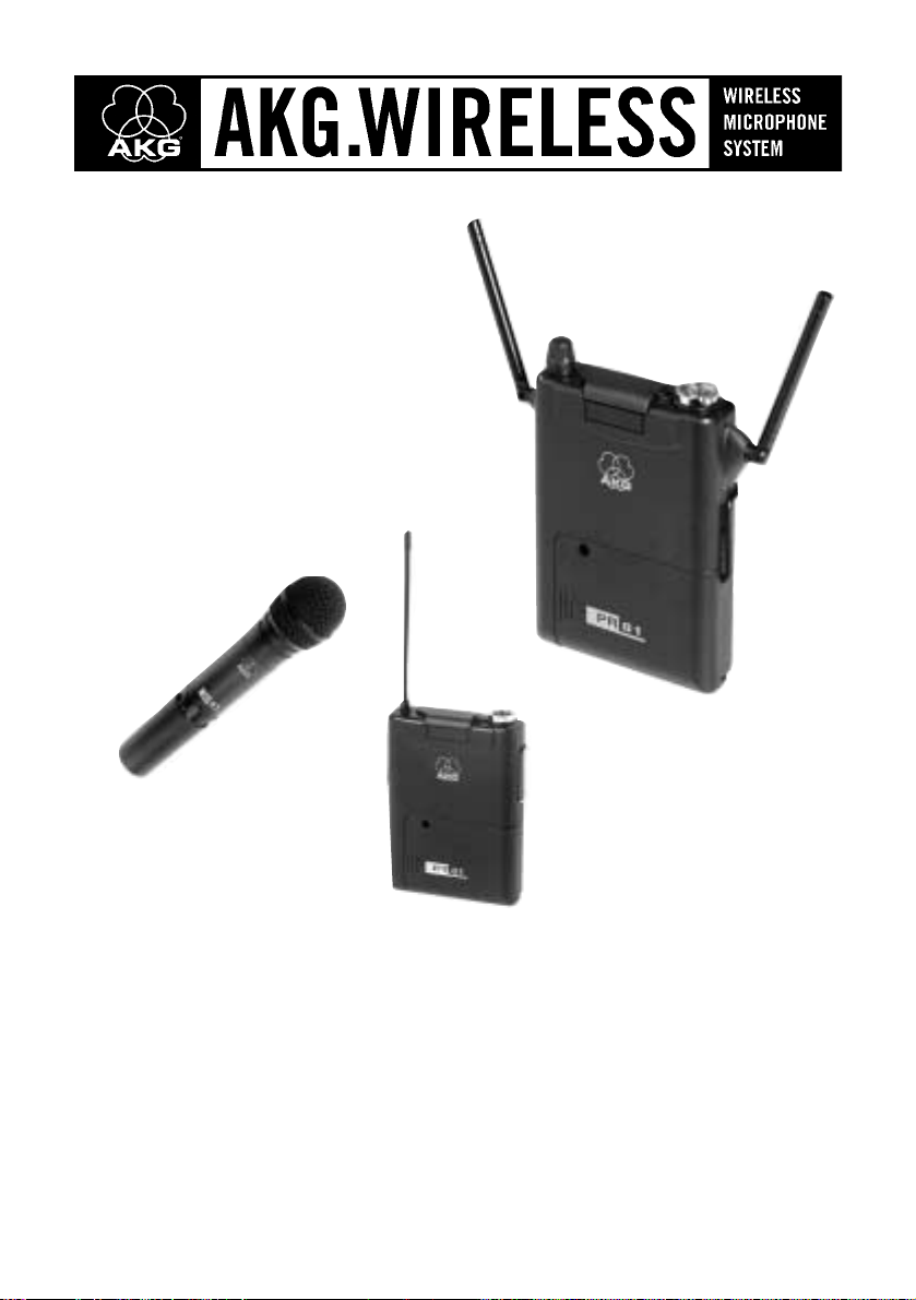
PR 81
HT 81
PT 81
User Instructions
Please read the manual before using the equipment!

Page
PART I: GENERAL . . . . . . . . . . . . . . . . . . . . . . . . . . . . . . . . . . . . . . . . . . . 18
0 FCC Statement . . . . . . . . . . . . . . . . . . . . . . . . . . . . . . . . . . . . . . . . . . . . 18
1 Safety and Environment . . . . . . . . . . . . . . . . . . . . . . . . . . . . . . . . . . . . 18
1.1 Safety . . . . . . . . . . . . . . . . . . . . . . . . . . . . . . . . . . . . . . . . . . . . . 18
1.2 Environment . . . . . . . . . . . . . . . . . . . . . . . . . . . . . . . . . . . . . . . . 18
2 Description . . . . . . . . . . . . . . . . . . . . . . . . . . . . . . . . . . . . . . . . . . . . . . . 18
2.1 Introduction . . . . . . . . . . . . . . . . . . . . . . . . . . . . . . . . . . . . . . . . 18
2.2 Unpacking . . . . . . . . . . . . . . . . . . . . . . . . . . . . . . . . . . . . . . . . . 19
2.3 Optional Accessories . . . . . . . . . . . . . . . . . . . . . . . . . . . . . . . . . 19
2.4 Frequencies . . . . . . . . . . . . . . . . . . . . . . . . . . . . . . . . . . . . . . . . 20
2.5 Ordering Transmitters and Receivers. . . . . . . . . . . . . . . . . . . . . . 20
PART II: PR 81 RECEIVER. . . . . . . . . . . . . . . . . . . . . . . . . . . . . . . . . . . . . 20
1 Description . . . . . . . . . . . . . . . . . . . . . . . . . . . . . . . . . . . . . . . . . . . . . . . 20
1.1 General. . . . . . . . . . . . . . . . . . . . . . . . . . . . . . . . . . . . . . . . . . . . 20
1.2 Controls . . . . . . . . . . . . . . . . . . . . . . . . . . . . . . . . . . . . . . . . . . . 20
1.3 Audio Output . . . . . . . . . . . . . . . . . . . . . . . . . . . . . . . . . . . . . . . 21
2 Setting Up . . . . . . . . . . . . . . . . . . . . . . . . . . . . . . . . . . . . . . . . . . . . . . . . 21
2.1 Selecting the Receiving Frequency . . . . . . . . . . . . . . . . . . . . . . . 21
2.2 Powering . . . . . . . . . . . . . . . . . . . . . . . . . . . . . . . . . . . . . . . . . . 22
2.3 Mounting the Receiver on a Camera . . . . . . . . . . . . . . . . . . . . . . 23
2.4 Using the Belt Clip . . . . . . . . . . . . . . . . . . . . . . . . . . . . . . . . . . . 23
2.5 Audio Connection . . . . . . . . . . . . . . . . . . . . . . . . . . . . . . . . . . . 23
2.6 Connecting Headphones. . . . . . . . . . . . . . . . . . . . . . . . . . . . . . . 24
2.7 Connecting to a Camera and Headphones . . . . . . . . . . . . . . . . . 24
2.8 Aligning the Antennas . . . . . . . . . . . . . . . . . . . . . . . . . . . . . . . . . 24
2.9 Color Code . . . . . . . . . . . . . . . . . . . . . . . . . . . . . . . . . . . . . . . . . 24
PART III: HT 81 HANDHELD TRANSMITTER . . . . . . . . . . . . . . . . . . . . . . 25
1 Description . . . . . . . . . . . . . . . . . . . . . . . . . . . . . . . . . . . . . . . . . . . . . . . 25
1.1 Controls . . . . . . . . . . . . . . . . . . . . . . . . . . . . . . . . . . . . . . . . . . . 25
1.2 Interchangeable Microphone Elements . . . . . . . . . . . . . . . . . . . . 25
2 Setting Up . . . . . . . . . . . . . . . . . . . . . . . . . . . . . . . . . . . . . . . . . . . . . . . . 26
2.1 Selecting the Carrier Frequency . . . . . . . . . . . . . . . . . . . . . . . . . 26
2.2 Microphone Element . . . . . . . . . . . . . . . . . . . . . . . . . . . . . . . . . . 26
2.3 Inserting and Testing Batteries . . . . . . . . . . . . . . . . . . . . . . . . . . 26
2.4 Color Code . . . . . . . . . . . . . . . . . . . . . . . . . . . . . . . . . . . . . . . . . 26
PART IV: PT 81 BODYPACK TRANSMITTER . . . . . . . . . . . . . . . . . . . . . . 27
1 Description . . . . . . . . . . . . . . . . . . . . . . . . . . . . . . . . . . . . . . . . . . . . . . . 27
1.1 Controls . . . . . . . . . . . . . . . . . . . . . . . . . . . . . . . . . . . . . . . . . . . 27
1.2 Microphones. . . . . . . . . . . . . . . . . . . . . . . . . . . . . . . . . . . . . . . . 27
2 Setting Up . . . . . . . . . . . . . . . . . . . . . . . . . . . . . . . . . . . . . . . . . . . . . . . . 27
2.1 Selecting the Carrier Frequency . . . . . . . . . . . . . . . . . . . . . . . . . 27
2.2 Inserting and Testing Batteries . . . . . . . . . . . . . . . . . . . . . . . . . . 28
2.3 Connecting and Using Microphones . . . . . . . . . . . . . . . . . . . . . . 28
2.4 Color Code . . . . . . . . . . . . . . . . . . . . . . . . . . . . . . . . . . . . . . . . . 28
PART V: OPERATING NOTES. . . . . . . . . . . . . . . . . . . . . . . . . . . . . . . . . . . 28
1 Adjusting Transmitter and Receiver . . . . . . . . . . . . . . . . . . . . . . . . . . 28
1.1 Adjustments . . . . . . . . . . . . . . . . . . . . . . . . . . . . . . . . . . . . . . . . 28
1.2 Multichannel Systems . . . . . . . . . . . . . . . . . . . . . . . . . . . . . . . . . 29
2 Cleaning . . . . . . . . . . . . . . . . . . . . . . . . . . . . . . . . . . . . . . . . . . . . . . . . . 29
PART VI: APPENDIX. . . . . . . . . . . . . . . . . . . . . . . . . . . . . . . . . . . . . . . . . . 30
1 Troubleshooting . . . . . . . . . . . . . . . . . . . . . . . . . . . . . . . . . . . . . . . . . . . 30
2 Specifications . . . . . . . . . . . . . . . . . . . . . . . . . . . . . . . . . . . . . . . . . . . . . 31
3 Frequency List . . . . . . . . . . . . . . . . . . . . . . . . . . . . . . . . . . . . . . . . . . . . 92
17
Table of Contents
1.1 Safety
1.2 Environment
2.1 Introduction
1. Spill no liquids on the equipment and do not drop any objects
through the ventilation slots in the equipment.
2. Do not place the equipment near heat sources such as radiators,
heating ducts, or amplifiers, etc. and do not expose it to direct sun-
light, excessive dust, moisture, rain, mechanical vibrations, or
shock.
1. Be sure to dispose of used batteries as required by local waste dis-
posal rules. Never throw batteries into a fire (risk of explosion) or
garbage bin.
2. When scrapping the equipment, remove the batteries, separate the
case, circuit boards, and cables, and dispose of all components in
accordance with local waste disposal rules.
Dear Customer:
Thank you for purchasing an AKG product. This Manual contains important instruc-
tions for setting up and operating your equipment. Please take a few minutes to
read the instructions below carefully before operating the equipment. Please
keep the Manual for future reference. Have fun and impress your audience!
18
PART I: GENERAL
I
FCC Statement
This equipment has been tested and found to comply with the limits for a Class B digital device, pursuant to
Parts 74, 15, and 90 of the FCC Rules. These limits are designed to provide reasonable protection against harm-
ful interference in a residential installation. This equipment generates, uses, and can radiate radio frequency ener-
gy and, if not installed and used in accordance with the instructions, may cause harmful interference to radio
communications. However, there is no guarantee that interference will not occur in a particular installation. If this
equipment does cause harmful interference to radio or television reception, which can be determined by turning
the equipment off and on, the user is encouraged to try to correct the interference by one or more of the follo-
wing measures:
• Reorient or relocate the receiving antenna.
• Increase the separation between the equipment and the receiver.
• Connect the equipment into an outlet on a circuit different from that to which the receiver is connected.
• Consult the dealer or an experienced radio/TV technician for help.
Shielded cables and I/O cords must be used for this equipment to comply with the relevant FCC regulations.
Changes or modifications not expressly approved in writing by AKG Acoustics may void the user’s authority to
operate this equipment.
This device complies with Part 15 of the FCC Rules. Operation is subject to the following two conditions: (1) this
device may not cause harmful interference, and (2) this device must accept any interference received, including
interference that may cause undesired operation.
1 Safety and Environment
2 Description
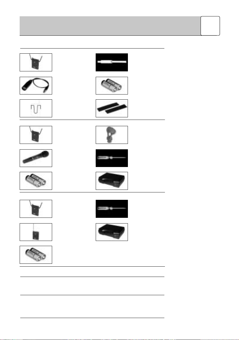
2.2 Unpacking
2.2.1 PR 81 Receiver
2.2.2 Handheld System
2.2.3 Bodypack System
2.3 Optional
Accessories
2.3.1 PR 81
2.3.2 HT 81
The PR 81 portable receiver is available separately or as a complete system with
an HT 81 handheld transmitter or PT 81 bodypack transmitter.
Please check that the package contains all the components listed above for your
system. If anything is missing contact your AKG dealer immediately.
PA 81 supply adapter for supply voltages between 5 V DC and 18 V DC
MK HP connecting cable for headphones
MK HP/C connecting cable for cameras and headphones
W 880 foam windscreen for D 880 WL1
W 3001 foam windscreen for D 3700 WL1 and C 5900 WL1
W 23 foam windscreen for C 535 WL1
CC 60 Color Coding Kit
19
PART I: GENERAL
I
1 PR 81 receiver
1 mini XLR to XLR
connecting cable
1 belt clip
1 screwdriver
2 AA size 1.5 V bat-
teries
Velcro tape for
camera mounting
1 PR 81 receiver
with
accessories
1 HT 81 handheld
transmitter
2 AA size 1.5 V bat-
teries for the
handheld trans-
mitter
1 SA 43 stand
adapter
1 screwdriver
1 carrying case
1 PR 81 receiver
with
accessories
1 PT 81 bodypack
transmitter
2 AA size 1.5 V bat-
teries for the
bodypack trans-
mitter
1 screwdriver
1 carrying case
2.3.3 PT 81
2.4 Frequencies
2.5 Ordering
Transmitters and
Receivers
1.1 General
1.2 Controls
1.2.1 Top Panel
Refer to section 1.3 Audio
Output.
CB 40 bag
Color Coding Kit
The PR 81 portable receiver, HT 81 handheld transmitter, and PT 81 bodypack
transmitter have been factory programmed for up to 15 selectable carrier fre-
quencies. A carrier frequency label on the receiver, on the handheld transmitter,
or on the bodypack transmitter indicates the Frequency Set the unit uses and all
available carrier frequencies.
For currently available Frequency Sets and frequencies suited for intermodulati-
on-free simultaneous operation, refer to the Frequency Lists in Part VI.
If you wish to order additional transmitters or receivers operating on the same set
of frequencies as your original equipment, be sure to state the designation of your
original Frequency Set and the serial number of the original device. We need this
information to make sure your new equipment will be compatible with the original
units.
The PR 81 is a portable diversity receiver you can wear on the belt or in a shirt or
jacket pocket. You may also use the supplied Velcro fastener to mount the
receiver on a camcorder. The PR 81 operates in a UHF band from 710 MHz to
860.9 MHz using a switching subband that is up to 3 MHz wide. Subject to local
frequency allocations, you can switch the PR 81 to one of up to 15 different carrier
frequencies.
1a POWER I/O: on/off switch.
1b POWER LED: indicates battery status:
LED flashes momentarily on switching power ON and extinguishes: batteries
are O.K.
LED does not illuminate on switching power ON: no or dead batteries are in
the battery compartment.
LED constantly lights brightly: batteries will be dead in about 60 minutes.
1c RF LED: Indicates the field strength of the received signal and the squelch
status:
LED lighting green: optimum signal strength.
LED lighting red: the received signal is muted because the squelch is engag-
ed or the receiver has been set to a different channel than the transmitter.
LED does not light: power to the receiver is OFF, no batteries are in the bat-
tery compartment, or the batteries are dead.
1d AF LED: Indicates the received audio level:
LED lighting green and flashing red on peaks: optimum audio level.
LED lighting red: audio section is overloaded.
LED does not light: audio level is too low.
1e Rotary control: Sets the volume level of the headphone output.
1f Security cover: This rotatable cover prevents the POWER switch (1a) from
being actuated unintentionally. The indicator LEDs will remain visible even if
the security cover is closed.
20
PART I: GENERAL
I
PART II: PR 81 RECEIVER
II
1 Description

1.2.2 Front Panel
1.2.3 Rear Panel
1.3 Audio Output
Important:
2.1 Selecting the
Receiving Frequency
1g Antennas: Being a diversity receiver, the PR 81 uses two antennas in order
to receive the transmitter signal at two different points in space. The diversity
circuit will automatically activate the antenna that provides the better signal.
1h Color code platelet: If you use the receiver within a multichannel system,
you can remove the black plastic platelet and replace it with a different color
platelet from the optional Color Coding Kit. This allows you to identify the
various channels clearly and easily.
1i Battery compartment: Accepts the supplied 1.5 V dry batteries, recharge-
able batteries of the same size (not supplied), or the optional PA 81 supply
adapter.
1j SQUELCH: The squelch will mute the receiver if the received signal is too
weak so the related noise or the self-noise of the receiver will not become
audible when the transmitter is switched OFF. Set the SQUELCH control to
minimum before switching power to the receiver ON for the first time. (For
details, refer to Part V, section 1.)
1k CHANNEL: This rotary switch selects the desired receiving frequency.
1l Battery compartment cover.
1m
Screwdriver: A detachable screwdriver is provided on the inside of the bat-
tery compartment cover (1l) for adjusting the SQUELCH and CHANNEL
controls.
1n Carrier frequency table: Sticker indicating the available carrier frequencies
and the frequency set for which your receiver has been programmed.
1o Approval marks.
1p Belt clip for fixing the receiver on your belt.
The AUDIO OUT 3-pin mini XLR connector (1r) on the receiver top panel provides
a fixed-level line output and an adjustable mono headphone output. The rotary
control (1e) lets you adjust the volume level of the headphones output.
The AUDIO OUT connector (1c) is wired as follows:
Pin 1: ground
Pin 2: line output (fixed level)
Pin 3: headphone output (adjustable)
In order to avoid overloading the headphone amplifier, do not connect head-
phones with an impedance of less than 16 Ω to the headphone output.
Prior to inserting batteries into the receiver, set the transmitter and the receiver to
the same carrier frequency. The carrier frequency tables on the transmitter (2h, 3k)
and receiver (1I) indicate the channel numbers corresponding to the various car-
rier frequencies.
1. If the belt clip (1p) is attached to the receiver, remove the belt clip (1p) first so
you can open the battery compartment (1I):
Use a screwdriver as a lever to lift both ends of the belt clip (1p) out of the
fixing holes in the receiver side panels.
2. To open the battery compartment (1I), press down on the arrow symbol on the
battery compartment cover (1l) and push the battery compartment cover (1l)
in the direction of the arrow away from the receiver.
3. Remove the screwdriver (1m) from the battery compartment cover (1l).
4. Use the screwdriver (1m) to set the CHANNEL selector (1k) to the desired
channel.
5. Set the transmitter to the same channel referring to section 2.1 in Part III:
HT 81 Handheld Transmitter or Part IV: PT 81 Bodypack Transmitter.
21
PART II: PR 81 RECEIVER
II
2 Setting Up
 Loading...