

Page 1
WMS 40
Service Manual
*
Feb., 2007
Last modifications:
New part number pos. 15 page 6
Correction of part number's page 6
New part number pos.17 page 12
Part number for XL1, page 20
Designation of KR3 crystal corrected from 19115330 to 19115530
Page 22 connector: remark added
HT40: parts added
Page 20: CF1,3 part number corrected from 17001073 to 17201073
Crystals and ceramic filters for HT, PT and SR added
___________________________________________________________________________
AKG Acoustics GmbH, A Harman International Company, Lemböckgasse 21 - 25, A-1230 Wien Austria
Tel.: +(43 1) 86654 - 0; Fax.: +(43 1) 86654 - 1514; service@akg.com
Page 1 of 24
Page 2
a Harman international company
WMS 40
The complete WMS 40 system:
The actual frequency is not differentiated by item number!
WMS 40 HT/US – Set with US power supply: 7611X0001
WMS 40 HT/EU – Set with EU power supply: 7612X0001
WMS 40 HT/UK – Set with UK power supply: 7613X0001
WMS 40 PT/US – Set with US power supply: 7611X0002
WMS 40 PT/EU – Set with US power supply: 7612X0002
WMS 40 PT/UK – Set with US power supply: 7613X0002
WMS 40 PT/US/Aerobic – Set with C444 and US power supply: 7611X0003
WMS 40 PT/EU/Aerobic – Set with C444 and EU power supply: 7612X0003
HT 40, handheld transmitter only: 7600X0001
PT 40, bodypack transmitter only: 7600X0002
SR40/US, receiver only with US power supply: 7601X0003
SR40/EU, receiver only with EU power supply: 7602X0003
SR40/UK, receiver only with UK power supply: 7603X0003
General remarks
This manual contains technical information on the system functions and
design. Exploded views and lists of all available mechanic parts and electronic
assemblies are added. Further a list of electronic components for one specific
frequency for both handheld and bodypack transmitters and receiver is added
for better technical understanding and trouble shooting. However we do not
stock or sell electronic components contained in those electronic components
lists. When ordering frequency depending boards please state part number
plus required frequency.
All measurement values are nominal if not otherwise specified. All
data subject to change without prior notice . All rights reserved. The
contents of this manual shall be used for service purposes only. Any
use of the information given herewith by third parties without
permission of the copyright owner is strictly forbidden!
© 2000 by AKG Acoustics GmbH, A Harman International Company,
A-1230 Wien, Austria.
Contacts:
e-mail: service@akg.com
Page 2 of 26
Page 3

a Harman international company
a Harman international company
WMS 40
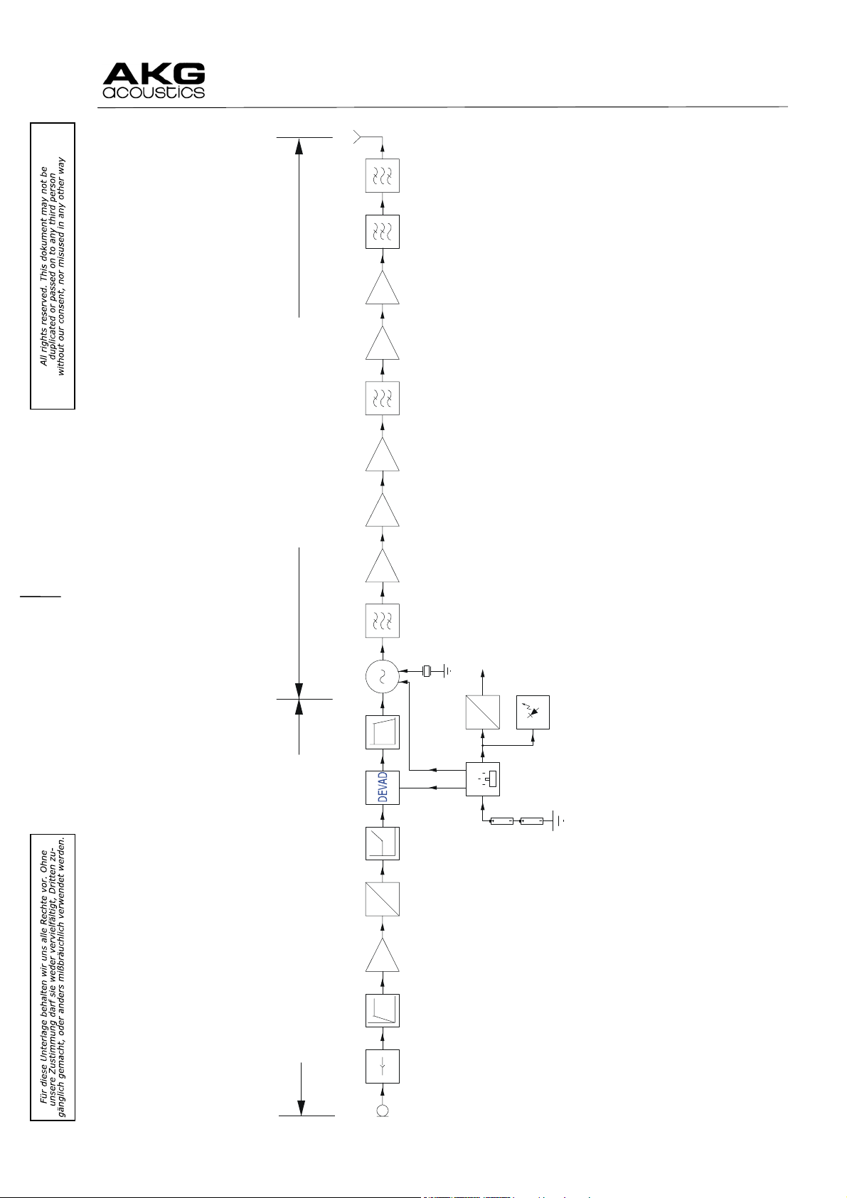
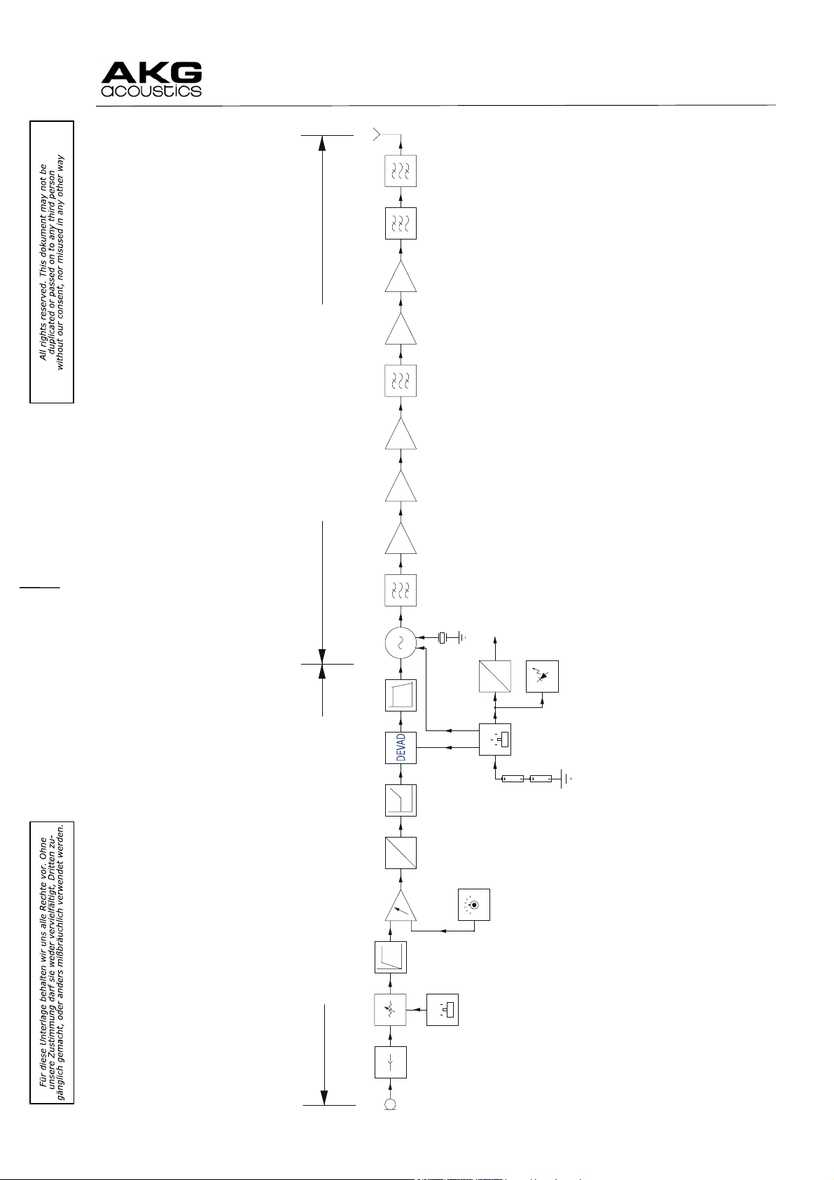
Short description Transmitter HT40:
Audio part:
The dynamic unit (D880) is connected via L1-L2-C6-C7 (RF-filter), to the MICAMP
The MICAMP is built as an amplifier, which is a part of the NE575- integrated circuit and has
a gain of 8.8dB. It also forms the LOCUT
ressor.
COMP
filter at 30 Hz. Then the signal is fed to the
Here the dynamic of the amplitude is reduced to its half value, expressed in dB. This
compressor is built with the integrated circuit NE575 from Signetics. In the feedback loop of
the amplifier (Pin 12 and 14) there is the variable gain cell inserted. The variable gain cell
is controlled by the rectified output voltage of the amplifier. C60 smoothes the rectified
signal an controls the variable gain cell. C60 defines the so called time constant of the
compressor. This feedback loop leads in an compression of the input signal. R7-R8-C10
build the DC path in the feedback loop.
The second amplifier is used to build the PREEM
phasis circuit, which boosts the higher
frequencies with an time constant of 50usec and a fixed gain of 7.9dB at the lower
frequencies.
The DEV
iation ADjustment is realized with the potentiometer R16. Here at an input level of
100mV/1kHz the deviation is adjusted to 15kHz, which is the nominal modulation. Also at
MUTE-position of the main switch, the signal is here shorted.
Q2 with the additional parts form the HICUT
filter at app. 25 kHz/3rd order.
Via C29-R28-C30-R30 the signal modulates the CCO.
RF part:
The UHF Signal is generated by a crystal controlled oscillator CCO
stages (AMP1
The third harmonic of the CCO is filtered by BPF1
filtered by BPF2
filter BPF3
, AMP2, AMP3, AMP4).
, after 3 doubler stages Ftransmit/2 is
. After the output amplifier AMP5 the signal is filtered by LPF and a ceramic
.
and multiplier amplifier
SETCode Transmitter Frequency Cryst all Frequency Color
US54 710,400MHz 14,800MHz reddish brown
US58 734,600MHz 15,304MHz purple
EU62 802,525MHz 16,719MHz warm red
EU63 812,800MHz 16,933MHz yellow
UK69A 854,900MHz 17,810MHz violet
UK69B 858,200MHz 17,879MHz green
ISM1 863,100MHz 17,981MHz melon yellow
ISM2 864,375MHz 18,008MHz cool gray
SP1 848,750 MHz 17,6822 MHz skyblue
SP2 851,750 MHz 17,7447 MHz yellow green
KR3 745,650 MHz 15,5344 MHz mintgreen
KR4 750,900 MHz 15,6438 MHz dark grey
Power supply:
The internal voltage of 3.9V is generated from 2 AA size batteries with a DC/DC
converter.
stage.
Page 3 of 24
Page 4
a Harman international company
ANT
LPF
Ftransmit
AMP3 AMP4AMP2MICAMP BPF1 BPF2 BPF3
WMS 40
HT40-block schematics
UHF-frequency rangeAF-frequency 40Hz ... 20KHz
doubler doubler doubler doubler
Ftransmit/16 Ftransmit/2 Ftransmit
XT2
3.9V
CCO AMP1 AMP5 LPF
HICUTLOCUT
COMP PREEMWIRE
OFF
23KHz
Order3
MUTE
Order1
3.1KH z
1
2
Ftransmit/48
DC
DC
DC/DC
UBat t
OFF
MUTE
ON
SWITCH
LOWBATT
BATTERY
Order
2
40Hz
2 wires
MIC
Page 4 of 26
Page 5
a Harman international company
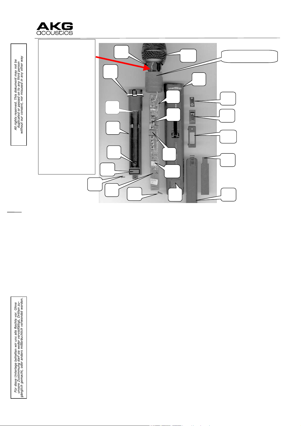
4
2
16
13 10 11 15 14 18 16 19
Attention: Before
reassembly twist
stranded wires
leading to capsule
in counterdirection to the
way of screwing in
the threaded
sleeve. Otherwise
the wires will
break.
Achtung: Vor dem
Zusammenbau die
Litzen zur Kapsel
im Gegensinn zur
Schraubrichtung
der Gewindehülse
verdrillen, da sonst
die Anschlüsse
abreissen!
WMS 40
Part nbr. :31404010
8
7
3
5
12
6
17
20
1
9
Page 5 of 26
Page 6
a Harman international company
WMS 40
Printed circuit main board, complete, tested 80004012 1
Printed circuit dc/dc board, complete, tested 80004013 2
ON/MUTE/OFF switch 92100400 3
Crystal 14.8003MHz (For US54, 710.400MHz) reddish brown
Crystal 14.8128MHz (For US54B, 711,000MHz) skyblue 19114811 4
Crystal 15.3045MHz (For US58, 734.600MHz) purple 19115301 4
Crystal 15.354MHz (For US58B, 736.975MHz) yellowgreen 19115350 4
Crystal 15.602 MHz (For US60A, 748.875MHz) green 19115600 4
Crystal 15.6576MHz (For US60B, 751.550MHz) dark purple 19115650 4
Crystal 16.7196MHz (For EU62, 802.525MHz) warm red 19116710 4
Crystal 16.7732MHz (For EU62B, 805.100MHz) pink 19116772 4
Crystal 16.9336MHz (For EU63, 812.800MHz) yellow 19116930 4
Crystal 16.9399MHz (For EU63B, 813.100MHz) light red 19116931 4
Crystal 17.8107MHz (For UK69A, 854.900MHz) violetblue 19117810 4
Crystal 17.8795MHz (For UK69B, 858.200MHz) green 19117871 4
Crystal 17.9815MHz (For ISM1, 863.100MHz) melon yellow 19117980 4
Crystal 18.0081MHz (For ISM2, 864.375MHz) cool gray 19118000 4
Crystal 18.0180MHz (For ISM3, 864.850MHz) violet 19118011 4
Crystal 15.5344MHz (For KR3, 745.650MHz) mint green 19115530 4
Crystal 15.6438MHz (For KR4, 750.900MHz) dark gray 19115640 4
Crystal 17.6822MHz (For SP1, 848.750MHz) 19117680 4
Crystal 17.7447MHz (For SP2, 851.750MHz) 19117740 4
Crystal 16.846MHz (For JP1, 808.625MHz) greenbrown 19116840 4
Crystal 16.857MHz (For JP2, 809.125MHz) light blue 19116850 4
Ceramic Filter 710.151MHz (For US54) 19307100 20
Ceramic Filter 734.151MHz (For US58) 19307340 20
Ceramic Filter 747.141MHz (For KR3) 19374710 20
Ceramic Filter 750.141MHz (For KR4) 19307500 20
Ceramic Filter 802.151MHz (For EU62) 19308020 20
Ceramic Filter 812.151MHz (For EU63) 19308120 20
Ceramic Filter 854.151MHz (For UK69A) 19308540 20
Ceramic Filter 858.151MHz (For UK69B) 19308580 20
Ceramic Filter 864.152MHz (For ISM1) 19308640 20
Ceramic Filter 864.152MHz (For ISM2) 19308640 20
Ceramic filters for further frequencies on request 20
Battery compartment 24200010 5
Battery contact (helical spring) 36304010 6
Battery contact (plate) 36205150 7
Housing tube, printed 27004010 8
Antenna cover, black 21504010 9
Antenna cover, orange 21504013 9
Antenna cover, yellow 21504014 9
Antenna cover, red 21504012 9
Antenna cover, brown 21504011 9
Antenna cover, pink 21504017 9
Antenna cover, green 21504015 9
Antenna cover, violet 21504016 9
Antenna cover, grey 21504018 9
ON/MUTE/OFF label with LED lens 22004010 10
ON/MUTE/OFF slider 25204010 11
Frame for ON/MUTE/OFF slider 22204010 12
Battery door 20104040 13
Capsule 2610Z0034 14
Top grill (39004010) new 9999N07180 15
Housing screw 33002060 16
Rubber plate 65045140 17
Ring 36104010 18
Cover 30818090 19
Stand adapter 23200010 --
Description Part number Item
19114801 4
Short description Transmitter PT40:
Audio part:
The input signal is connected at Pin2 via L13L14C44C72 (RFfilter), to the MICAMP
(with Pin1 = ground). The supply voltage of 3.9V for the microphones is connected via R68
at pin 3 of the connector . For microphone application Pin2 and Pin3 has to be shorten in
the connector of the microphone. The MICAMP is built as an amplifier, which is a part of the
NE575 integrated circuit and has a variable gain of 0dB to 21dB. It also forms the LOCUT
filter at 30 Hz and the MIC/LINE switch is situated here, which reduces the input signal by
app. 14dB at line position.
Then the signal is fed to the COMP
ressor. Here the dynamic of the amplitude is reduced to
its half value, expressed in dB. This compressor is built with the integrated circuit NE575
from Signetics. In the feedback loop of the amplifier (Pin 12 and 14) is the variable gain
cell inserted. The variable gain cell is controlled by the rectified output voltage of the
stage
Page 6 of 26
Page 7
a Harman international company
WMS 40
amplifier. C18 smoothes the rectified signal an controls the variable gain cell and is the so
called timeconstant of the compressor. This feedback loop leads in an compression of the
input signal. R45R46C24 build the dcpath in the feedback loop.
The second amplifier is used to build the preemphasis circuit, which boosts the higher
frequencies with an time constant of 50usec and a fixed gain of 7.9dB for the lower
frequencies.
The deviationadjustment is realized with the potentiometer VR3. Here at an inputlevel of
300mV at 1kHz (and the inputgain set to 0dB=minimumgain) the deviation is adjusted to
15kHz, which is the nominal modulation. Also at MUTEposition of the main switch, the
signal is here shorted.
Q7with the additional parts form the HICUTfilter at app. 25 kHz / 3. order.
Via C25R69C26R17 the signal modulates the CCO.
RF part:
The UHF Signal is generated by a crystal controlled oscillator CCO
stages (AMP1
The third harmonic of the CCO is filtered by BPF1
filtered by BPF2
filter BPF3
, AMP2, AMP3, AMP4).
, after 3 doubler stages Ftransmit/2 is
. After the output amplifier AMP5 the signal is filtered by LPF and a ceramic
.
and multiplier amplifier
Power supply:
The internal voltage of 3.9V is generated from 2 AA size batteries with a DC/DC
converter.
Page 7 of 26
Page 8
a Harman international company
WMS 40
ANT
LPF
Ftransmit
AMP3 AMP4AMP2
UHF-frequency rangeAF-frequency 40Hz ... 20KHz
PT40-block schematics
doubler doubler doubler do ubler
BPF1 BPF2 BPF3
CCO AMP1 AMP5 LPF
HICUT
COMP PREEM
40Hz
LOCUT
Ftransmit/16 Ftransmit/2 Ftransmit
XT2
3.9V
Ftransmit/48
OFF
23KHz
Order3
MUTE
Order1
3.1KHz
1
2
MICAMP
GC
Order
2
DC
DC
DC/DC
UBatt
OFF
MUTE
ON
SWITCH
-22...0d B
LOWBATT
BATTERY
GAINPOT
ATT
CON
MIC
0dB -14dB
MIC/LINE
3 Pins
Page 8 of 26
Page 9

a Harman international company
3
13 11
WMS 40
15
2
16
1
7
4
6
5
14
12
10
8
9
Description Part number Item
Printed circuit board, complete, tested 80000402 1
Antenna 83200820 2
ON/MUTE/OFF switch 92100700 3
MIC/LINE switch 92100190 4
Sensitivity trimmer potentiometer 11001043 5
Crystal: see parts list for HT40, Pos 4 6
Housing, bottom shell 21600400 7
Housing, top shell, printed 20300400 8
Battery door 20100400 9
Battery contact (single helical spring) 36300400 10
Battery contact (plate) 36200400 11
Battery contact (plate with helical spring) 36003340 12
Belt clip 36400151 13
Housing screw 33026120 14
Mic socket 90605030 15
Ceramic Filter: see parts list for HT40, Pos 20 16
Page 9 of 26
Page 10

a Harman international company
WMS 40
Short description Receiver SR40:
The SR40 is a stationary non diversity receiver applying a double conversion conception.
The receiver is non switchable, his reception frequency in the UHF range is:
SET CODE FRx: F
US54 710,400MHz 654,400MHz 36,356MHz 56,0MHz
US58 734,600MHz 678,600MHz 37,700MHz 56,0MHz
EU62 802,525MHz 746,525MHz 41,474MHz 56,0MHz
EU63 812,800MHz 756,800MHz 42,044MHz 56,0MHz
UK69A 854,900MHz 798,900MHz 44,383MHz 56,0MHz
UK69B 858,200MHz 802,200MHz 44,567MHz 56,0MHz
ISM1 863,100MHz 807,100MHz 44,839MHz 56,0MHz
ISM2 864,375MHz 808,375MHz 44,910MHz 56,0MHz
LO1: XT1: FIF1: FLO2=XT2: FIF2:
45,3MHz 10,7MHz
45,3MHz 10,7MHz
45,3MHz 10,7MHz
45,3MHz 10,7MHz
45,3MHz 10,7MHz
45,3MHz 10,7MHz
45,3MHz 10,7MHz
45,3MHz 10,7MHz
The elements determining the reception frequency are the band pass filter BPF1 and the
crystal of local mixer oscillator XT1
RFPart:
The front end consists of a ceramic pass band filter BPF1
and a low pass filter LPF. The 1st MIXER1 converts the RF signal to the 1st
AMP1
intermediate frequency of 56MHz, the 2
intermediate (demodulation) frequency 10.7MHz.
nd
The 2
the input of the demodulator IC (LIMAMP
The 1
harmonic is filtered out by BPF4
filtered by BPF5, BPF6
The 2
intermediate frequency is band pass filtered (BPF2,3), amplified (AMP2) and gets to
st
mixer oscillator (CCO1) is designed as a crystal controlled oscillator (the 3rd
) and multiplier amplifiers AMP3 and AMP4. The LO signal is
nd
mixer oscillator (CCO2) is crystal controlled too, his frequency is 45,3MHz.
and is 56MHz below the reception frequency.
nd
MIXER2 converts the signal to the 2nd
and DEMOD).
, a bipolar transistor amplifier
AudioPart:
The audio signal from DEMOD
ulator (BA4110IFdemodulator) is amplified by AFAMP with
U11Pin123. Here the output signal is adjusted to 500mV/1kHz at 15kHz deviation.
Then the signal runs to the MUTE
stage, which is the second half of U11. Muting is realized
with Q29, which shortens the feedback path. Q29 is controlled by the RSSI signal.
The RSSIsignal comes from the IFcircuit BA4110. U7 forms an COMPARATOR
, which
switches the MUTEtransistor Q29 at RSSIlevel lower than 98dBm. This value can be
adjusted via SQUELCH
Q25 builds an HICUT
phasis circuit. The frequencies above 3 kHz are decreased with first order
DEEM
potentiometer VR1.
filter at 20 kHz/2nd order. Amplifier Pin17/18/19 of NE575 forms the
(timeconstant 50 µsec).
Then the signal is expanded with the EXP
ander circuit NE575. Here the original level
behavior of the input signal at the transmitter input is restored. The expander time
constant is defined by C48.
The second free amplifier of NE575 is used as buffer before the volume control section.
With VR2 (VOLUME)
(35mV). The next stage is a amplifier with a gain of 3.9dB OUTAMP
C39 separates the dcvoltage from the signal and then the signal is fed to the XLR
6.3mm
JACK. Q31 and Q32 build a CLICKSUPPRessioncircuit. In the OFFposition of the
the output level can be adjusted from line level (500mV) to mic. level
.
and
main switch this transistors are turned on. If the receiver is turned ON, the transistors
remain ON for a short time (by C50), so the clicksignals caused by the amplifiers is
suppressed.
The balanced output has symmetrical impedance, which is built by R84/R87 and R88/R89.
The receiver is powered by an external device which is to be connected at the rear panel (DC
jack POWER
internal used voltage (+8V) is stabilized by the DC circuitry (VREG
) and can be turned on and off by a switch at the front panel (ON/OFF). The
).
Page 10 of 26
Page 11

a Harman international company
XLR
BAL
OUTAMP
1
UNBAL
GC
2
JACK
6.3mm
35mV..500mV
CLICKSUPPR
VOLUME
+8VDC
VREG
3.1KHz
Order1
DEEM EXP
20k
Order2
RFLED
Controll
MUTE HICUT
POWER
ON/OFF
12V
DC
300mA
AF-frequency 40Hz ... 20KHz
AFAMP
GC
AF
IF
COMPARATOR
DEMOD
-98..-70dBm
SQUELCH
WMS 40
SR40-block schematics
RSSI
10.7MHz
AMP2 LIMAMP
FLO2
XT2
FIF1 FIF2
56MHz
FRx
LPF
LPF
CCO2
FLO1
45.3MHz
FLO1
AMP1 MIXER1 MIXER2
BPF5
FLO1/3
BPF1 BPF2 BPF3
UHF-frequency range
ANT
doubler
BPF4 BPF6
FLO1/6
XT1
FLO1/18
CCO1 AMP3 AMP4
Page 11 of 26
Page 12

a Harman international company
6 7
11 12 13 8 18 17 16 15 14 19 20 21
23 24 25
WMS 40
4
22
1.1
1.2
1
9
5
10
2
26
Description Part number Item
Tuner, complete, tested PLEASE STATE REQUIRED FREQUENCY!!! 80004010 1
Crystal 45,300 MHz 19204530 1.1
Crystal 36.3556MHz (For US54, 710.400MHz) 19236350 1.2
Crystal 37.7000MHz (For US58, 734.600MHz) 19237700 1.2
Crystal 41.4736MHz (For EU62, 802.525MHz) 19241470 1.2
Crystal 42.0444MHz (For EU63, 812.800MHz) 19242040 1.2
Crystal 44.3833MHz (For UK69A, 854.900MHz) 19244380 1.2
Crystal 44.5667MHz (For UK69B, 858.200MHz) 19244560 1.2
Crystal 44.8389MHz (For ISM1, 863.100MHz) 19244830 1.2
Crystal 44.9097MHz (For ISM2, 864.375MHz) 19244900 1.2
Crystal 38.3139MHz (For KR3, 745.650MHz) 19238310 1.2
Crystal 38.6056MHz (For KR4, 750.900MHz) 19238600 1.2
Crystal 44.0416MHz (For SP1, 848.750MHz) 19244040 1.2
Crystal 44.2083MHz (For SP2, 851.750MHz) 19244200 1.2
Crystals for further frequencies on request
Main board, complete, tested 80000400 2
Antenna 33398010 4
Power switch 92301900 5
Power switch knob 25100090 6
Volume potentiometer 11200061 7
Volume potentiometer knob 25000060 8
LED green 16531245 9
LED red 16551242 10
Squelch potentiometer 11001042 11
XLR socket 90400081 12
1/4" jack socket 90106470 13
Power supply socket 90000140 14
Tension relief bracket 25300400 15
Screw driver holder 24400121 16
Screw driver 309232000 17
Housing (bottom shell) 21100400 18
Housing (top cover) 20000400
Front panel, printed 22000400 19
Front panel foil, printed 30100400 20
Side panel, left, right 22300400 21
Screw 2,6x5 33026051 22
Screw 3x8 33030830 23
Screw 2,6x7 33026070 24
Screw 2x6 33002060 25
Screw 2,5x30 33025300 26
Power supply 230 volts Europe version 94014250
Power supply 230 volts UK version 94015930
Power supply 117 volts US version 94014260
Page 12 of 26
Page 13

a Harman international company
WMS 40
The following parts lists refer to the WMS40 with 863.100 MHz. Crystals and ceramic filters see
parts list of HT40, PT40 and SR40
MICROPHONE HT40 Freq. 863.100MHz
R1, 24 Carbon 10 ohm
R4, 19 Carbon 1 kohm
R13, Carbon 10 kohm
R28 Carbon 3.9 kohm
R5, 20, 27, 83 Carbon 10 kohm
R82 Carbon 1.2 kohm
R17 Carbon 12 kohm
R40 Carbon 150 kohm
R15 Carbon 18 kohm
R18 Carbon 220 ohm
R33 Carbon 2.2 kohm
R11 Carbon 22 kohm
R29 Carbon 22 kohm
R3, 31, 35 Carbon 220 kohm
R7, 8 Carbon 30 kohm
R21, 39 Carbon 33 kohm
R37, 38, 40 Carbon 330 kohm
R25 Carbon 4.7 kohm
R30 Carbon 47 kohm
R32 Carbon 470 kohm
R6 Carbon 5.6 kohm
R2 Carbon 56 kohm
R81 Carbon 68 ohm
R80 Carbon 680 ohm
R22 Carbon 68 kohm
R23 Carbon 680 kohm
R14 Carbon 8.2 kohm
R41 Carbon 82 kohm
R16
C24
C13 Electrolytic
C52 Ceramic 0,3 pF 50V
C39, 40 Ceramic
C43, 44, 45, 53,
57, 58
C42, 54
C11 Ceramic
Ceramic
C41, 68 Ceramic
C6, 14, 67 Ceramic
C31, 33 Ceramic
C32, 38, 66 Ceramic
C16, Ceramic
20K, POZ3AN51203N ±30% SMT
Metallized
Polyester Film
Ceramic 2 ρF 50V ±0.25ρF NPO 13100023
Ceramic 3 ρF
0.0068μF
22 μF
1 ρF
4.7 ρF
5 ρF
10 ρF
15 ρF
30 ρF
50 ρF
68 ρF
±5%
±5%
±1%
±5%
±5%
±5%
±1%
±5%
±1%
±1%
±5%
±1%
±5%
±5%
±5%
±5%
±5%
±5%
±5%
±5%
±5%
±5%
±5%
±5%
±5%
±5%
±1%
±5%
63V
6.3V 12522031
50V
50V ±0.25ρF NPO 13100033
50V
50V
50V
50V
50V
50V
50V
SMT 10310003
SMT 10310023
SMT 10310031
SMT
SMT
SMT 10312023
SMT 10312031
SMT
SMT 10318031
SMT 10322011
SMT 10322023
SMT 10322031
SMT 10322033
SMT 10322043
SMT 10330033
SMT 10333033
SMT 10333043
SMT 10347023
SMT 10347033
SMT 10347043
SMT 10356023
SMT 10356033
SMT 10368003
SMT 10368013
SMT 10368033
SMT 10368043
SMT 10382021
SMT 10368033
±5%
±0.25ρF
±0.25ρF
±0.25ρF
±0.25ρF
±0. 5ρF
±5%
±5%
±5%
±5%
12306820
NPO
NPO 13100013
NPO 13100042
NPO 13100053
NPO 13100103
NPO 13100153
NPO 13100303
NPO 13100503
NPO 13100683
10310033
11302030
Page 13 of 26
Page 14

a Harman international company
C7, 18 Ceramic 100 ρF 50V ±5% NPO 13101003
C48, 49, 50, 56,
69, 70, 81
C22 Ceramic 2200 pF 50V
C36, 37, 88 Ceramic
C3, 4 Ceramic
C60 Ceramic
C28, 82, 84, 85,
86, 87
C8, 23 Ceramic
C2 Ceramic
Tantalum
C1, 10, 26, 27, 34,
35, 83
C17, 21, 29, 30 Tantalum
C5, 9, 25, 61 Tantalum
C51, 55 210P TZVY2Z100A110 13520100
L3, 4, 5, 6 LQP11A15nG00T1M SMT 14715000
L10 LQP11A22nG14 SMT 14722000
L11 LQN21A100n SMT
L8
L1, 2 82 nH
U2 Philips NE575D SMT 15105750
U1 3V SIKEO, S81230SGUPDQBT1 15181230
Q1 CTR, FMW1, T148 SMT 15301480
Q13 ROHM 2SD2098 15320980
Q2, 3, 14 Toshiba 2SC2712GR, SMT 15327120
Q4, 5, 6, 8 Toshiba 2SC2714Y 15327140
Q7, 9 NEC 2SC3356 15333560
D1 LED
D2 VARACTOR Toshiba 1SV161 16201610
D5 ZENER ROHM 3V9 16603900
D6 ROHM RB451 16904510
T2, 3 A294SNST1191Z 19011910
T4 A294SNST1192Z 19011920
T5 A294SNST1388Z 19013880
T1 A294SNST1414Z 19014140
T6 H054444168 19041680
L7
SW1 Slide Switch, SS019P223MAmHPA3 92100400
XT1 NIC17.9815MHz 19117980
J107, 109 3 P (2mm) 61003PASG1 90300032
Ceramic 0.001 μF 50V ±10% X7R 13101023
±10%
0.01 μF
0.047 μF
1 μF
Ceramic
Tantalum 10 μF 10V ±20% SMT 13401063
Center Freq. 864MHz 3dB Band Width ±1.5MHz
10 μF
220 ρF
470 ρF
0.1 μF
2.2 μF
4.7 μF
100 μH
3φ, Red
50V
25V
16V
50V +80%20% 13101066
50V
50V
35V
16V
16V
±10%
±10%
±10%
±5%
±5%
±20%
±20%
±20%
TDK NL3225221R2K 14710100
TDK NL322522082J 14782001
16530012
X7R
X7R 13101033
X7R 13114733
X7R 13101051
NPO 13102203
NPO 13104703
SMT 13401043
SMT 13402253
SMT 13404753
19308640
WMS 40
Page 14 of 26
Page 15

a Harman international company
TRANSMITTER PT40 Freq. 863.100MHz
R47, 55 Carbon 10 ohm
R36, 50, 66 Carbon 1 kohm
R67 Carbon 100 ohm
R53 Carbon 10 kohm
R69 Carbon 3.9 kohm
R18, 38, 73 Carbon 10 kohm
R57 Carbon 100 kohm
R43 Carbon 1.2 kohm
R62 Carbon 22 kohm
R6 Carbon 1.5 kohm
R41 Carbon 150 kohm
R61 Carbon 56 kohm
R20 Carbon 220 ohm
R29 Carbon 2.2 kohm
R35 Carbon 22 kohm
R44, Carbon 22 kohm
R25, 51, 70, 71 Carbon 220 kohm
R45, 46 Carbon 30 kohm
R56 Carbon 33 kohm
R32, 40 Carbon 330 kohm
R4, 68 Carbon 4.7 kohm
R17, 59 Carbon 47 kohm
R72 Carbon 470 kohm
R54 Carbon 56 kohm
R34 Carbon 68 ohm
R33, 52 Carbon 680 ohm
R37, 39 Carbon 68 kohm
R63 Carbon 680 kohm
R1 Carbon 8.2 kohm
R42 Carbon 82 kohm
±5%
±5%
±5%
±1%
±5%
±5%
±5%
±5%
±1%
±5%
±5%
±1%
±1%
±5%
±1%
±5%
±5%
±5%
±5%
±5%
±5%
±5%
±5%
±5%
±5%
±5%
±5%
±5%
±1%
±5%
SMT 10310003
SMT 10310023
SMT 10310013
SMT 10310031
SMT
SMT 10310033
SMT 10310043
SMT 10312023
SMT
SMT 10315023
SMT
SMT
SMT 10322011
SMT 10322023
SMT 10322031
SMT 10322033
SMT 10322043
SMT 10330033
SMT 10333033
SMT 10333043
SMT 10347023
SMT 10347033
SMT 10347043
SMT 10356033
SMT 10368003
SMT 10368013
SMT 10368033
SMT 10368043
SMT 10382021
SMT 10368033
VR2 Panasonic 10 kohm MATEVND8YA03B24 11001043
VR3
C19
C6 Electrolytic
C7 Electrolytic
C10, 35 Ceramic 0,3 pF 50V
Ceramic
C45, 47, 53, 56, 57
C39, 49
C62 Ceramic
Ceramic
C70 Ceramic
C42 Ceramic
C40 Ceramic
20K, POZ3AN51203N ±30% SMT
Metallized
Polyester Film
Ceramic 2 ρF
Ceramic 3 ρF
0.0022μF
100 μF
22 μF
1 ρF
4.7 ρF
5 ρF
7 ρF
10 ρF
12 ρF
63V
6.3V 12501071
6.3V 12522031
50V
50V ±0.25% NPO 13100023
50V ±0.25% NPO 13100033
50V
50V
50V
50V
50V
±5%
±0.25%
±0.25%
±0.25%
±0.25%
±0.25%
±0. 5%
±5%
11302030
NPO
NPO 13100013
NPO 13100042
NPO 13100053
NPO 13100073
NPO 13100103
NPO 13100123
WMS 40
Page 15 of 26
Page 16

a Harman international company
C50, 72 Ceramic 15 ρF 50V ±5% NPO 13100153
C38, 52 Ceramic
C35, 37, 43 Ceramic 50 ρF 50V ±5% NPO 13100503
C59, 64 Ceramic
C44, 63 Ceramic 100 ρF 50V ±5% NPO 13101003
C29, 46, 54, 65, 66
C28 Ceramic 2200 pF 50V ±10% X7R
C33, 41, 48, 58,
67, 69, 76
C51, 61 Ceramic
C18 Ceramic
C1, 3, 4, 23, 75 Ceramic
C68 Ceramic
C60 Ceramic
Tantalum
C13 Tantalum
C2, 9, 11, 15, 16,
24, 73, 74,
C12, 20, 21, 25, 26 Tantalum
C8, 17 Tantalum
C14, 71 210P TZVY2Z100A110 13520100
L5, L8 LQP11A10nG14 SMT 14710000
L6, 7 LQP11A15nG00T1M SMT 14715000
L3, 11, 12 LQP11A22nG14 SMT 14722000
L13 LQN21A100n SMT
L4
L13, 14 82 nH
U1 Philips NE575D SMT 15105750
U2 3V SIKEO, S81230SGUPDQBT1 15181230
Q19 CTR, FMW1, T148 SMT 15301480
Q4 ROHM 2SD2098 15320980
Q7, 8, 23 Toshiba 2SC2712GR, SMT 15327120
Q2, 10, 11, 21 Toshiba 2SC2714Y 15327140
Q12, 16 NEC 2SC3356 15333560
D3 LED
D6 VARACTOR Toshiba 1SV161 16201610
D2 ZENER ROHM 3V9 16603900
D8 RECTIFIER ROHM 1SR154400 16701541
D1 ROHM RB451 16904510
T1, 4 A294SNST1191Z 19011910
T6 A294SNST1388Z 19013880
T2 A294SNST1192Z 19011920
T3 A294SNST1414Z 19014140
L1 H054444168 19041680
L2
SW1 Slide Switch, SS019P022BBmPA7 92100190
SW2 Slide Switch, SS070P823MBbPB6 92100700
30 ρF
68 ρF
Ceramic 0.001 μF
Ceramic 0.01 μF 50V ±10% X7R 13101033
0.047 μF
1 μF
10 μF
220 ρF
330 ρF
0.1 μF
1 μF
Tantalum 10 μF 10V ±20% SMT 13401063
2.2 μF
4.7 μF
100 μH
3φ, Red
Center Freq. 864MHz 3dB Band Width ±1.5MHz
50V
50V
50V ±10% X7R 13101023
25V
16V
50V
35V
16V
16V
16V
±5%
±5%
±10%
±10%
V +80%20% 13101066
±5%
X7R 13103303
±20%
±20%
±20%
±20%
TDK NL3225221R2K 14710100
TDK NL322522082J 14782001
16530012
NPO 13100303
NPO 13100683
NPO 13114733
X7R 13101051
NPO 13102203
SMT 13401043
SMT 13401053
SMT 13402253
SMT 13404753
19308640
WMS 40
Page 16 of 26
Page 17

a Harman international company
XLT1 NIC17.9815MHz 19117980
Antenna Fixed Plate 34600400
J3 PCB Jack 2 P 90200022
WMS 40
Page 17 of 26
Page 18

a Harman international company
RECEIVER SR40 Freq. 863.1MHz
R69 Carbon 10 ohm
R87, 88 Carbon 100 ohm
R1 Carbon 100 ohm
R3, 8, 9, 56, 57,
77, 116
R40, 120 Carbon 10 kohm
R49, 59 Carbon 10 kohm
R34, 35, 39, 54, 82
R18, 32, 73 Carbon 120 kohm
R4 Carbon 1.5 kohm
R29, 30 Carbon 15 kohm
R61 Carbon 18 kohm
R6 Carbon 22 ohm
R62 Carbon 220 ohm
R12, 22 Carbon 2.2 kohm
R20, 46, 74 Carbon 22 kohm
R55, 67, 107 Carbon 220 kohm
R72 Carbon 2.2 Mohm
R44 Carbon 27 kohm
R2, 5, 47 Carbon 330 ohm
R43 Carbon 3.3 Kohm
R10, 11, 38, 118 Carbon 47 ohm
R117 Carbon 470 ohm
R15, 51, 78, 79,
80, 81
R65, 66, 85, 86 Carbon 47 kohm
R84, 89 Carbon 560 ohm
R83 Carbon 560 ohm
R26 Carbon 5.6 kohm
R68 Carbon 56 kohm
R119 Carbon 680 ohm
R7 Carbon 6.8 kohm
R76 Carbon 68 kohm
VR1 Carbon 10KΩ Panasonic EVND2YA03B14 11001042
VR2 Carbon 10 KA RK09K1110452 11200061
VR3 Carbon 20KΩ Panasonic MATEVND8YA03B24 11002040
VR4 Carbon 100KΩ Panasonic MATEVND8YA03B15 11001050
C14 Polyester
C32 Electrolytic
C31, 45 Electrolytic
C10, 25, 28, 36, 44
C49, 53 Electrolytic
C4,33 43 Electrolytic
C9 Electrolytic
C11 Electrolytic
Carbon 1 kohm
Carbon 100 kohm
Carbon 4.7 Kohm
0.0027 μF
Electrolytic 10 μF
2200 μF
0.1 μF
1 μF
100 μF
2.2 μF
220 μF
±5%
±1%
±5%
±5% 0603 10310023
±1%
±5%
±5% 0603 10310043
±5%
±5%
±5%
±1%
±5%
±5%
±5%
±5%
±5%
±5%
±1%
±5%
±5%
±5%
±5%
±5% 0603 10347023
±5%
±1%
±5%
±5%
±5%
±5%
±5%
±5%
50V
50V
50V
16V ±20% 12401063
16V
50V
16V
25V
0603 10310003
0603 10310011
0603 10310013
0603 10310031
0603 10310033
0603 10312043
0603 10315023
0603 10315033
0603 10318031
0603 10322003
0603 10322013
0603 10322023
0603 10322033
0603 10322043
0603 10322053
0603 10327031
0603 10333013
0603 10333023
0603 10347003
0603 10347013
0603 10347033
0603 10356011
0603 10356013
0603 10356023
0603 10356033
0603 10368013
0603 10368023
0603 10368033
±5%
±20%
±20%
±20%
±20%
±20%
±20%
12202726
12401046
12401056
12401073
12402256
12402273
12402294
WMS 40
Page 18 of 26
Page 19

a Harman international company
WMS 40
C19, 35, 37, 38,
39, 46
C50, 51, 52 Electrolytic
C2, 3, 15, 26, 27
C22 Ceramic
C75, 78, 103 Ceramic
C5, 12, 20, 24, 34,
55, 80
C1, 8, 107 Ceramic
C76, 77, 110, 111 Ceramic
C13, 17, 18, 21,
23, 73, 82, 102
C16, 84, 85 Ceramic
C74 Ceramic
C83 Ceramic
C48 Ceramic
L1
L2
L3
L4
U3 Rohm BA4110 15041100
U10 Philips NE575D SMT 15105750
U7 Rohm BA10393F 15110390
U9, 11 Rohm BA4558FEZ 15145580
Q30 Rohm CTR, IMX2 15300020
Q31 Rohm CTR, FMW1 15301480
Q18 Rohm 2SB1188R 15311880
Q16, 23, 25, 27,
29, 32
D7, D8 Silicon 1N4001 Hitachi 16140010
D1 LED
D2 LED
D6 Zener ROHM 5V1 SMT 16605101
D3 Zener ROHM 8V2 SMT 16608200
Q24, 28 ROHM DAN212K 16902120
Q17 ROHM DAN217 16902170
CF1 CDA10.7MA18A 17201073
J5 AF Output 6.3 mm
J4 DC Jack 2 mm
Balanced Jack 94M008P1 90400081
SW1 SPPJ22NE01 2P 92301900
Electrolytic 4.7 μF 50V ±20% 12404756
47 μF
Ceramic 27 ρF
50 ρF
100 ρF
Ceramic 0.001 μF 50V X7R 13101023
0.01 μF
220 ρF
Ceramic 0.022 μF 50V 10% X7R 13102233
680 ρF
470 ρF
0.0015 μF
1 μF
KOA LFC32 1 μH ±5%
TDK NL322522 100 μH ±5%
TDK NL3225226R8J 6.8 μH ±5%
Toshiba 2SC2712GR 15327120
4.7φ
4.7φ
50V
50V NPO 13100503
50V NPO 13101003
50V X7R 13101033
50V NPO 13102203
50V X7R 13106803
50V 13104703
50V X7R 13101523
16V 10% X7R 13101051
5.6 μH ±5%
RED 16504702
GREEN 16504705
±20%
NPO 13100273
14405600
90106470
90000140
12404765
14701000
14710100
14706800
Page 19 of 26
Page 20

a Harman international company
TUNER
R24 Carbon 0 ohm
R3, 6, 27, 39, 43
R23, 36 Carbon 2.2 kohm
R4, 5, 29 Carbon 4.7 kohm
R30 Carbon 5.6 kohm
R14 Carbon 10 ohm
R1, 2, 25 Carbon 10 kohm
R11 Carbon 47 ohm
R28, 38, 40, 42 Carbon 47 kohm
R26, 31 Carbon 82 kohm
R9, 10, 12, 13 Carbon 100 ohm
R8, 22
R35 Carbon 220 kohm
R7 Carbon 330 ohm
R41 Carbon 390 ohm
R12, 20 Carbon 560 ohm
C33, 45 Ceramic
C50 Ceramic
C54, 111 Ceramic
C12, 37 Ceramic
C52, 110 Ceramic
C51 Ceramic
C32, 35 Ceramic
C10, 31, 55 Ceramic
C13 Ceramic
C1, 26 Ceramic
C47 Ceramic
C30,40, 44, 49
C2, 27 Ceramic
C43 Ceramic
C53 Ceramic
C25, 36, 88 Ceramic
C3, 29, 34, 42, 46,
48, 84, 85
C28 Ceramic
C4, 5, 6, 8, 41, 73 Ceramic
C39, 47 Ceramic
C7, 38 Ceramic
L14 1.3GHz B69610G1307B412 4x4mm 14400130
L19 LQP11A10nG14 SMT 14710000
L17, 19 LQP11A15nG00T1M SMT 14715000
L16, 22 LQP11A22nG14 SMT 14722000
L15 LQP11A33nG00T1M SMT 14733000
L1, 9
±5%
Carbon 1 kohm
Carbon 100 kohm
1 ρF
1.5 ρF
3 ρF
4 ρF
5 ρF
7 ρF
8 ρF
10 ρF
12 ρF
15 ρF
20 ρF
Ceramic 27 ρF
30 ρF
50 ρF
68 ρF
100 ρF
Ceramic 0.001 μF 50V 10% X7R 13101023
0.01 μF
0.022 μF
220 ρF
470 ρF
1μH
±5% 0603
±5%
±5%
±5%
±5%
±5%
±5%
±5%
±5%
±5%
±5% 0603
±5%
±5%
±5%
±5%
50V
50V
50V
50V
50V
50V
50V
50V
50V
50V
50V
50V ±5% NPO 13100273
50V
50V
50V
50V
50V 10% X7R 13101033
50V 10% X7R 13102233
50V
50V
TDK NL3225221R0J 14701001
0603 10300003
10310023
0603 10322023
0603 10347023
0603 10356023
0603 10310003
0603 10310033
0603 10347003
0603 10347033
0603 10382033
0603 10310013
10310043
0603 10322043
0603 10333013
0603 10339013
0603 10356013
±5%
±5%
±5%
±5%
±5%
±5%
±5%
±5%
±5%
±5%
±5%
±5%
±5%
±5%
±5%
±5%
±5%
NPO 13100013
NPO 13100011
NPO 13100033
NPO 13100043
NPO 13100053
NPO 13100073
NPO 13100083
NPO 13100103
NPO 13100123
NPO 13100153
NPO 13100203
NPO 13100303
NPO 13100503
NPO 13100683
NPO 13101003
NPO 13102203
NPO 13104703
WMS 40
Page 20 of 26
Page 21

a Harman international company
WMS 40
L17 3.3 nH
L12 5.6 nH
L20 100nH
L2
L21 8.2 μH
L3, 5 0.47 nH
Q1, 2, 4, Toshiba 2SC2714Y 15327140
Q5 NEC 2SC3356 15333560
Q3 FieldEffect Toshiba FET 3SK151Y 15401510
VC1 6CTC10 4.5~20 RED TZBX4R200BA110 13520010 1R0.5K
CF1, 3 E10.7MH 17201073
BPF
L4, 10 A294SNST1192Z 19011920
L13 A294SNST1407Z 19014070
J1 2 P P2.54mm 90300023
J4 4 P P2.54mm 90300043
XL1 NIC45.3000MHz 19204530
XL2 NIC44.8389MHz 19244830
Center Freq. 864MHz 3dB Band Width ±1.5MHz
0.82 μH
LQG11A3N3S00 14700033
LQG11A5N6S00 14700056
TDK NL322522TR10J 14700100
KOA LFC320.82μH
KOA LFC328.2μH 14708200
TDK NL322522TR47J 14704710
14700820
19308640
Page 21 of 26
Page 22

Page 23

Page 24

Page 25

Page 26

 Loading...