

Page 1

A
Wireless In-Ear Monitoring System
Live Sound / Club Music
Theater
Rental
House of Worship
• Audio quality without any compromise
• Reference audio with ultra linear frequency response
• Diversity Receiver with two matched antennas ensures rel iable transmission
• Stable signal due to a new reference radio electronic desig n with narrow filter
• Quick frequency change function to support monitor engineers
• Manual radio signal attenuator for a robust radio q uality and more RF dynamic
IVM 4500 IEM Set
In-Ear Monitoring System
KG IVM 4500 IEM in-ear monitoring provides higher level audio quality without compromising reference capability and caters
to all needs of engineers with leading edge reference audio technology.
IVM 4500 IEM offers a highly diversified system, which includes high-end radio electronic and a manual radio signal attenuator
for more RF dynamic. Antenna diversity, with two matched antennas and a new reference radio electronic design
contribute to the stable signals of the receiver.
The enhanced frequency setup shows the number of free channels, and new preset groups supp ort TV channels. A quick
frequency change function supports monitor engineers throughout performances to make their projects easily adju stable.
With 30 MHz tuning range you can select 1200 frequencies and operate with up to 14 channels simultaneously within the
same frequency band. Receivers are powered by two AA size Alkaline (LR6), Lithium (FR6), AKG BP 4000 µC controlled
battery pack or Ni-MH rechargeable (HR6) battery and provide up to 10 hours of continuous operation.
Included in the IVM 4500 IEM system are the SPR 4500 IEM diversity receiver, the SST 4500 IEM transmitter and the IP 2
ear-channel headphones. The SPC 4500 antenna combiner, the SR A 2 W directional antenna and the RA 4000 W omnidirectional antenna complete the system.
Page 2
Wireless In Ear Monitoring System Wireless In-Ear Monitoring System
Live Sound / Club Music
Theater
Rental
House of Worship
• Stereo Transmitter with patented digital MPX generation
• Adjustable radio output power of 10, 20, 50 and 100 mW (country de pendent)
• Ultra linear frequency response
• Premium SNR
• Reference audio dynamic
• dbx professional digital signal processing
Low cut, compressor, equalizer and unique binaural room simulations for a natural listening experience
• Rugged half 19” metal housing diversity receiver
• Up to 14 pre-programmed frequenci es pe r group
• PC control optional HUB 4000 Q
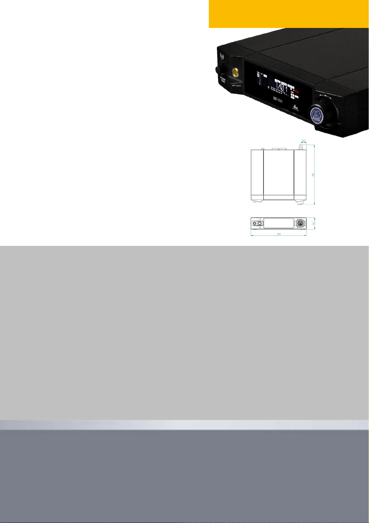
SST 4500 IEM
SST 4500 IEM Stereo Transmitter Specifications
Carrier frequency range Band 1: 650.1 to 680.5 MHz Band 5-TH: 790.1 to 805.9 MHz
Band 3-A: 720 to 750.5 MHz Band 5-IL: 794.1 to 805.9 MHz
Band 3-K: 740.1 to 751.9 MHz Band 7: 500.1 to 530.5 MHz
Band 4: 759.5 to 789.9 MHz Band 8: 570.1 to 600.5 MHz
Band 5-A: 790.1 to 819.9 MHz Band 9: 600.1 to 605.9 & 614.1 to 630.5 MHz
Band 5-JA: 797.125 to 805.875 MHz Band 9-U: 600.1 to 630.5 MHz
Switching bandwidth ≤ 30.5 MHz (country dependent)
Output Power 10, 20, 50 and 100mW selectable (country dependent)
Modulation FM, MPX Stereo
Audio bandwidth 35 – 20 000 Hz (± 3 dB)
T.H.D. ≤ 0.5 %
Audio Inputs 2 x combined XLR balanced / TS ¼” jack sockets unbalanced
Audio Outputs 2 x Loop TS ¼” jack sockets unbalanced
1 x Line TS ¼” jack sockets balanced
Headphones Output 1 x TS ¼” jack sockets balanced
Dimensions ½ 19 inch 1U rack, 200 mm (7.8 in.) × 44 mm (1 .7 in.) × 216 mm (8 .5 in.)
Net Weight 1070 g (2.36 lbs.)
Standard Accessories 1 UHF antennas, power supply, rack mount kit
Item number: SST 4500 3095H00..
Architects’ and Engineers’ Specifications
The stereo stationary transmitter shall operate over a 30 MHz UHF frequency range in one of 7 bands from 500 MH z to 823 MHz. The transmitter shall offe r up to
1200 discrete operating frequencies within that band. The transmitter shall provide a rugged half-rack metal case with backlit LC color display. An integrated signal
processor shall provide an adjustable low cut filter, equalizer-, binaural room simulati on-, and compressor presets. The transmitter shall provide indicators for
audio input level, gain reduction of compressor/limiter, activated audio-processing blocks, actual transmitting power, device name, frequ ency group und channel.
Rear panel BNC socket shall allow either the supplied antenna or a complex antenna network to be connected to the transmitter. The transmitter radio output
power shall be software adjustable up to 100mW. The squelch threshold shall be adjustable betw een –82 and –100 dBm. The transmitter’s audio bandwidth shall
be 35 Hz to 20 kHz; S/N 90 dB(A); THD <0.8% at 1 kHz and stereo, mono and dual function shall provided as well as a SR4500 fu nction for a stationary
transmission to a SR4500 receiver. Audio inputs shall comprise a XLR/jack hybrid connector with ±20 d B adjustable input gain. The transmitter shall provide two
1/4" TS jack audio loop outputs for flexible mix setups, a 1/4" TS stereo jack output for line signal and a 1/4" TS stereo jack output for headphones. A RJ11 data
port for connecting HUB 4000 Q communicating with Harman System Architect PC software shall be provided. The transmitter shall provide a lockable DC input
for the supplied 12 V DC power supply. The transmitter shall measure 200 x 216 x 44 mm (W x D x H) and weigh 1070 g. The transmitter shall be the AKG SST
4500 or equivalent.
Page 3

g
Wireless In-Ear Monitoring System
Live Sound / Club Music
Theater
Rental
House of Worship
• Diversity bodypack receiver with rugged metal housing
• Reference audio quality with ultra linear frequency response
• High-end and powerful headphon e amplifier
• Two matched antennas and a new reference radio electronic design ensure reliable transmission
• Enhanced automatic setup shows number of free channels
• Preset groups support TV channels
• Manual radio signal attenuator
• Quick change of individual programmed frequencies for monitor engineer s
• Stereo, Mono and Dual mode for individual mix
• Operates for up to ten hours off two AA size dry lithium batteries, six hours off two AA size dry
alkaline batteries and 7 hours off optional BP 4000 battery pack with µC controlled battery
management
SPR 4500 IEM
SPR 4500 IEM Transmitter Specifications
Carrier frequency range Band 1: 650.1 to 680.5 MHz Band 5-TH: 790.1 to 805.9 M Hz
Band 3-A: 720 to 750.5 MHz Band 5-IL: 794.1 to 805.9 MHz
Band 3-K: 740.1 to 751.9 MHz Band 7: 500.1 to 530.5 M Hz
Band 4: 759.5 to 789.9 MHz Band 8: 570.1 to 600 .5 MH z
Band 5-A: 790.1 to 819.9 MHz Band 9: 600.1 to 605.9 & 614.1 to 630.5 MHz
Band 5-JA: 797.125 to 805.875 MHz Band 9-U: 600.1 to 630.5 MHz
Switching bandwidth ≤ 30.5 MHz (country dependent)
Output Power 10, 20, 50 and 100mW selectable (country dependent)
Modulation FM, MPX Stereo
Channel separation > 40 dB(A)
Audio bandwidth 35 – 15 000 Hz (± 3 dB)
T.H.D. ≤ 0.8 %
SNR (A-weighted) typ. >90 dB(A)
Audio Output 3.5mm jack socket, 150 mW (rms)/16 Ohm
Battery life 6 bis 10 Stunden volume dependent, 2 Batteries AA or BP 4000
Dimensions 70 x 91 x 25 mm (2.8 x 3.5 x 1 in.)
Net Weight 165 g (0.36 lbs.)
Patents Remainin
Item number: SPR 4500 3096H00xx0
battery life (Patent no. AT 408.280, GB 2.349.230, US 6,344,730)
Architects’ and Engineers’ Specifications
The diversity bodypack receiver shall operate over a 30 MHz UHF frequency range in one of 7 b ands from 500 MHz to 823 MHz. The receiver shall offer up to 1,200
discrete operating frequencies within that band. The receiver shall operate on a diversity principle and shall be housed in a rugged metal case. The receiver shall provide
intermodulation-free frequencies from an integrated frequency database and an automatic function for finding an available frequency. Total harmonic distortion at 1 kHz
for rated deviation shall be no greater than 0.8% and stereo, mono and dual function for individual mix shall provided. The receiver shall provide a manual squelch
adjustment and a manual radio signal attenuator for optimum system operation. Headphone output shall be a 3.5 mm stereo jack connector. The bodyback receiver shall
be controlled by a jog and shall provide a backlit display with automatic power saving as well as a programmable LED (red/green) showing the overall system status.
The display shall indicate the transmitter battery capacity, as well as the radio signal input level, frequency, frequency group and chann el. The audio bandwidth of the
receiver shall be 35 Hz to 15 kHz; S/N 90 dB(A); THD at 1 kHz <0.8%. The receiver shall operate with a companding system that is complemented by the transmitter.
The diversity receiver shall provide a quick change of individual programmed frequencies to support monitor engineers. Charging contacts on the bottom panel shall
allow the easy charging of a battery pack inside the transmitter. The receiver shall operate off two AA size LR6 dry batteries, two AA size NiMH rechargeable batteries or
a µC controlled battery pack or two AA size FR6 lithium batteries. The receiver shall measure 70 x 91 x 25 mm an d weigh 165 g. The diversity bodypack receiver shall
be the AKG SPR 4500 IEM or equivalent.
Page 4

Wireless In-Ear Monitoring System
Live Sound / Club Music
Theater
Rental
House of Worship
• Stationary 4:1 combiner
• Powers transmitters via antenna lines
• Rugged half 19” all metal case
• Combines antenna signals of up to four SST 4500 IEM stereo transmitters
SPC 4500
SPC 4500 Combiner Specifications
Carrier frequency range 500 to 865 MHz
Max. Input Power 3 to 4 x 20mW inputs or 2 x 50mW inputs
System Gain 0 dB
Audio bandwidth 35 – 20 000 Hz (± 3 dB)
T.H.D. ≤ 0.5 %
Radio Signal Inputs 4 x BNC socket, 50 Ohm
Radio Signal Output 1 x BNC socket, 50 Ohm
Dimensions ½ 19 inch 1U rack, 200 mm (7.8 in.) × 44 mm (1 .7 in.) × 216 mm (8 .5 in.)
Net Weight 1193 g (2.6 lbs.)
Standard Accessories Power supply, rack mount kit
Item number: SPC 4500 3098H00010
Architects’ and Engineers’ Specifications
The 4:1 antenna combiner shall comprise a stackable, active wideband antenna booster an d antenna distribution system within a half-rack metal case and include
a rack mounting kit. The antenna combiner shall operate in a carrier frequency range of 500 to 865 MHz. The antenna combiner shall provide the following inputs,
outputs, controls, and indicators: 4 x 50 ohm BNC antenna input sockets, 1 x 50 ohm BNC antenna output socket. Green, orange and red status LED shall indicate
correct or incorrect function of the combiner. The transmitters connected to the antenna combiner shall be powered via the ap pro priate antenna cable. Unused
antenna outputs shall be automatically terminated with a 50 ohm terminal. A power supply for up to 4 SST 4500 IEM transmitter shall be available as an optional
accessory. The antenna combiner shall operate from 12 VDC and provide a lockable DC input for the supplied 12 V DC power supply. The combiner shall
measure 200 x 216 x 44 mm (7.8 x 8.5 x 1.7 in.), and weigh 1193 g (2.6 lbs.). The antenna combiner shall be the AKG SP C 4500 or equivalent.
Page 5

pply
IVM 4500 Components
IVM 4500 Set
• SST 4500 Stationary Transmitter
• SPR 4500 Bodypack Receiver
• IP 2 Ear Channel Headphones
• 19“ Rack Mount Kit
• 2x AA size LR6 Battery
• 12V EU/US/UK Power Supply
• ¼-Wave Antenna
Item number:
3097H00xx0
Antenna
SRA 2 W
• Passive Directional Antenna
• 50 Ohm
• 4-6 dB Gain
For use with short cable runs
RG58: <10 m/30 ft
RG213 or low loss cable: <20 m/60 ft
Item number:
3009H00150
RA 4000 W
• Passive Omni-Directional Antenna
• 50 Ohm
• 1-2 dB Gain
For use with short cable runs
RG58: <5 m/30 ft
RG213 or low loss cable: <10 m/30 ft
Item number:
2632H00310
SST 4500
• SST 4500 Stationary Transmitter
• 19“ Rack Mount Kit
• 12V EU/US/UK Power Supply
• ¼-Wave Antenna
Item number:
3095H00xx0
Wireless In-Ear Monitoring System
SPR 4500 Set
• SPR 4500 Bodypack Receiver
• IP 2 Ear Channel Headphones
• 2x AA size LR6 Battery
Item number:
3096H00xx0
Power Su
AC12 EU/US/UK 2000mA
• Wall Plug 12V/2A Power Supply
• EU connector
• US connector
• UK connector
One high current 12V/2A DC output feed
sthe power to SPC 4500 antenna splitter.
(Attention: SPC 4500 needs 2x 12V/2A!)
Via SPC 4500 four SST 4500 transmitter
sget the power through the antenna cable.
Item number:
7601H00110
SPC 4500
• SPC 4500 Stationary 1:4 Combiner
• 19“ Rack Mount Kit
• 12V EU/US/UK Power Supply
Item number:
3098H00010
PSU 4000
• PSU 4000 Stationary Power Supply
• 19“ Rack Mount Kit
• IEC Power Cable (optional)
• 3x lockable DC cable
Three high current 12V/2A DC outputs feed
the power to SPC 4500 antenna splitter.
(Attention: SPC 4500 needs 2x 12V/2A!) Via
SPC 4500 four SST 4500 transmitters get
the power through the antenna cable.
Item number:
2997H000x0
Architects’ and Engineers’ Specifications
SRA 2 W
The antenna shall be a passive directional antenna operating in the UHF range. The antenna gain of 4 dB shall allow for the use of RG 58 cables up to 10 m long or RG
213 cables up to 20 m long. The antenna shall feature an integrated, swivelling 3/8" stand adapter thread, and 50-ohm BNC connectors. The carrier frequency range of
the antenna shall be 500 MHz to 865 MHz, its antenna gain 4 dB. The passive directional antenna shall be the SRA 2 W from AKG.
RA 4000 W
The antenna shall be an passive omni-directional antenna operating in the UHF range. The antenna shall feature an 50-ohm BNC connectors, and include an SA 63
stand adapter. The carrier frequency range of the antenna shall be 500 MHz to 865 MHz, its antenna gain 1 dB. The omni-directional antenna shall be the RA 4000 W
from AKG.
Page 6

Wireless In-Ear Monitoring System
4 Channel IVM 4500 System
SRA 2 W
Directional Antenna
PSU 4000 - Power Supply Unit
Mixer
8 x XLR cable
4 Channel System Part List
• 4 x 3097H00xx0 IVM 4500 IEM (3095H00xx0 - SST 4500 IEM + 3096H00xx0 - SPR 4500 IEM)
• 1 x 3098H00xx0 SPC 4500
• 1 x 3009H00150 SRA 2 W or 1 x 2632H00310 RA 4000 W
• 4 x 6000H02060 MK PS – RG58 cable 0.65m
• 1 x 2455Z00620 MK A5 – RG58 cable 5m
• 2 x 7601H00110 AC12 EU/US/UK 2 000mA or 1 x 2997H000x0 PSU 4000
SST 4500 – Transmitter
SST 4500 – Transmitter
SST 4500 – Transmitter
SST 4500 – Transmitter
 Loading...