

AKG HUB-4000 Owners manual
Bedienungsanleitung . . . . . . . . . . . . . . . S. 2
Bitte vor Inbetriebnahme des Gerätes lesen!
User Instructions. . . . . . . . . . . . . . . . . . . p. 6
Please read the manual before using the equipment!
Mode d’emploi. . . . . . . . . . . . . . . . . . . . p. 10
Veuillez lire cette notice avant d’utiliser le système!
Istruzioni per l’uso . . . . . . . . . . . . . . . . p. 14
Prima di utilizzare l’apparecchio, leggere il manuale
Modo de empleo . . . . . . . . . . . . . . . . . . p. 18
¡Sirvase leer el manual antes de utilizar el equipo!
Instruções de uso . . . . . . . . . . . . . . . . . p. 22
Por favor leia este manual antes de usar o equipamento!
HUB 4000
WMS4000
wireless microphone system
network concentrator

1 Sicherheit und Umwelt
1.1 Sicherheit
1.2 Umwelt
2.1 Einleitung
Siehe Fig. 3.1 und 3.2. Details siehe
Bedienungsanleitung SR 4000.
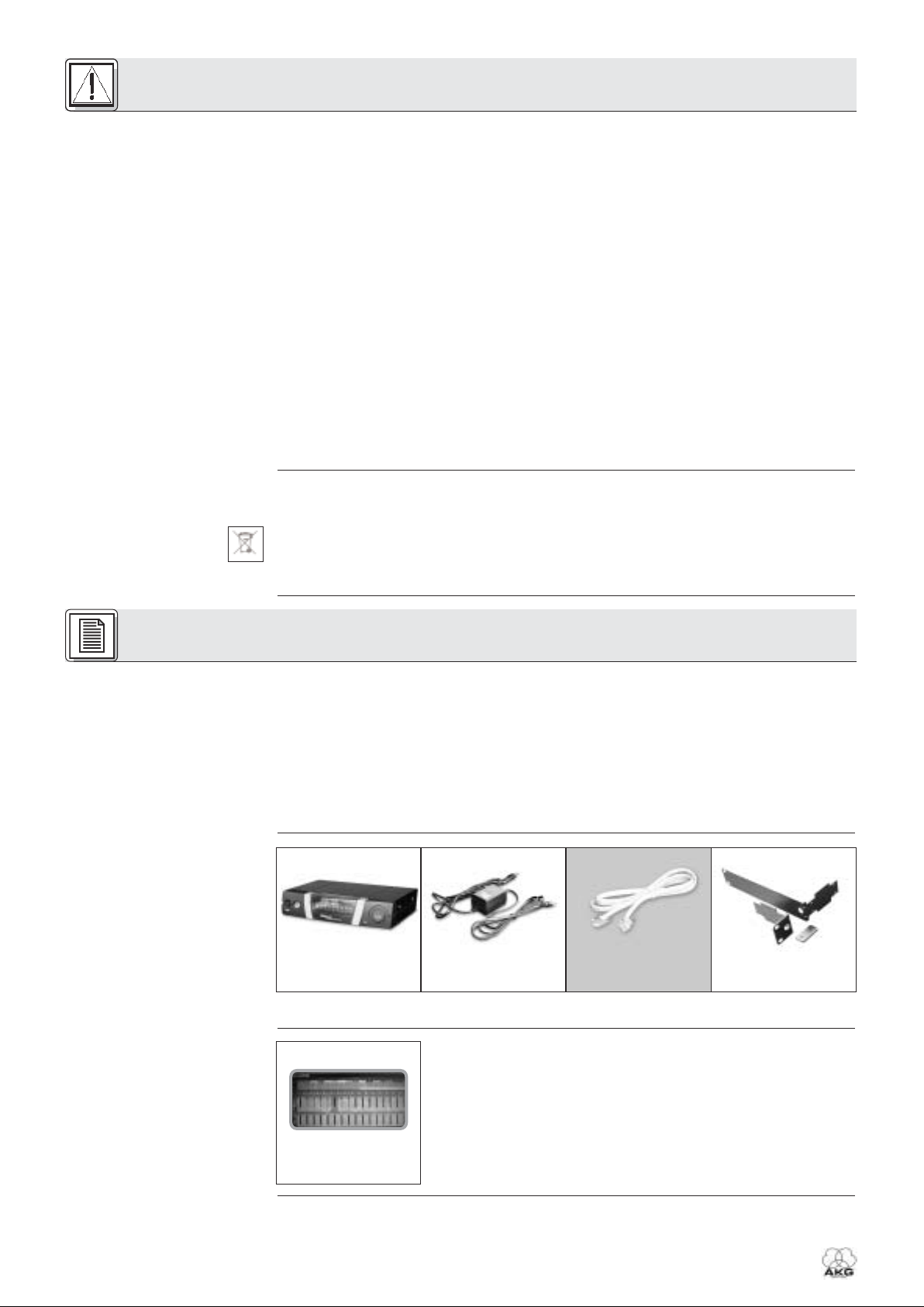
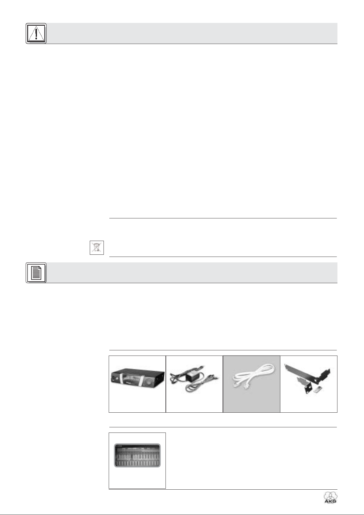
2.2 Lieferumfang
2.3 Optionales Zubehör
2
HUB 4000
1. Schütten Sie keine Flüssigkeiten auf das Gerät und lassen Sie keine sonstigen Gegenstände durch
die Lüftungsschlitze in das Gerät fallen.
2. Das Gerät darf nur in trockenen Räumen eingesetzt werden.
3. Das Gerät darf nur von autorisiertem Fachpersonal geöffnet, gewartet und repariert werden. Im
Inneren des Gehäuses befinden sich keinerlei Teile, die vom Laien gewartet, repariert oder ausgetauscht werden können.
4. Prüfen Sie vor Inbetriebnahme des Gerätes, ob die auf dem mitgelieferten Netzgerät angegebene
Betriebsspannung der Netzspannung am Einsatzort entspricht.
5. Betreiben Sie das Gerät ausschließlich mit dem mitgelieferten Netzgerät mit einer Ausgangsspannung
von 12 V DC. Andere Stromarten und Spannungen könnten das Gerät ernsthaft beschädigen!
6. Brechen Sie den Betrieb der Anlage sofort ab, wenn ein fester Gegenstand oder Flüssigkeit in das
Geräteinnere gelangen sollte. Ziehen Sie in diesem Fall sofort das Netzkabel des Netzgeräts aus der
Steckdose und lassen Sie das Gerät von unserem Kundendienst überprüfen.
7. Ziehen Sie das Netzkabel des Netzgeräts bei längerer Nichtverwendung aus der Steckdose. Bitte
beachten Sie, dass bei angestecktem Netzgerät das Gerät nicht vollständig vom Netz getrennt wird,
wenn Sie es ausschalten.
8. Stellen Sie das Gerät nicht in der Nähe von Wärmequellen wie z. B. Radiatoren, Heizungsrohren,
Verstärkern, usw. auf und setzen Sie es nicht direkter Sonneneinstrahlung, starker Staub- und
Feuchtigkeitseinwirkung, Regen, Vibrationen oder Schlägen aus.
9. Verlegen Sie zur Vermeidung von Störungen bzw. Einstreuungen sämtliche Leitungen, speziell die der
Mikrofoneingänge, getrennt von Starkstromleitungen und Netzleitungen. Bei Verlegung in Schächten oder
Kabelkanälen achten Sie darauf, die Übertragungsleitungen in einem separaten Kanal unterzubringen.
10.Reinigen Sie das Gerät nur mit einem feuchten, aber nicht nassen Tuch. Ziehen Sie unbedingt das
Netzkabel des Netzgeräts vorher aus der Steckdose! Verwenden Sie keinesfalls scharfe oder scheuernde Reinigungsmittel sowie keine, die Alkohol oder Lösungsmittel enthalten, da diese den Lack
sowie die Kunststoffteile beschädigen könnten.
11.Verwenden Sie das Gerät nur für die in dieser Bedienungsanleitung beschriebenen Anwendungen. Für
Schäden infolge unsachgemäßer Handhabung oder missbräuchlicher Verwendung kann AKG keine
Haftung übernehmen.
1. Das Netzgerät nimmt auch bei ausgeschaltetem Gerät einen geringen Strom auf. Um Energie zu sparen, ziehen Sie daher das Netzkabel des Netzgeräts von der Netzsteckdose ab, wenn Sie das Gerät
längere Zeit nicht benützen.
2. Wenn Sie das Gerät verschrotten, trennen Sie Gehäuse, Elektronik und Kabel und entsorgen Sie alle
Komponenten gemäß den dafür geltenden Entsorgungsvorschriften.
3. Die Verpackung ist recyclierbar. Entsorgen Sie die Verpackung in einem dafür vorgesehenen
Sammelsystem.
Vielen Dank, dass Sie sich für ein Produkt aus dem Hause AKG entschieden haben. Bitte lesen Sie die
Bedienungsanleitung aufmerksam durch, bevor Sie das Gerät benützen, und bewahren Sie die
Bedienungsanleitung sorgfältig auf, damit Sie jederzeit nachschlagen können. Wir wünschen Ihnen viel
Spaß und Erfolg!
Der HUB 4000 ist ein von AKG entwickelter Ethernet-Hub mit Netzwerkanschluss zum Steuern von bis
zu 8 Empfängern SR 4000 von einem PC aus. Die dazu erforderliche Software MCS 4000 ist separat
erhältlich und läuft unter Mac OS, Windows und LINUX. (Die genauen Systemvoraussetzungen finden Sie
im MCS 4000 Handbuch.)
Für größere Anlagen mit mehr als 8 Kanälen können Sie die entsprechende Anzahl HUB 4000 mittels handelsüblicher Ethernet-Hubs kaskadieren.
Sie können das Gerät entweder freistehend aufstellen oder mit dem mitgelieferten 19"-Montageset in ein
19"-Rack einbauen.
Kontrollieren Sie bitte, ob die Verpackung alle oben angeführten Teile enthält. Falls etwas fehlt, wenden
Sie sich bitte an Ihren AKG-Händler.
2 Beschreibung
1 Ethernet-Hub
HUB 4000
1 Inline-Netzgerät
(wenn
auf der Verpackung angekreuzt)
8 Datenkabel 1 Rackmontageset
Steuersoftware
MCS 4000
2.4 Bedienelemente
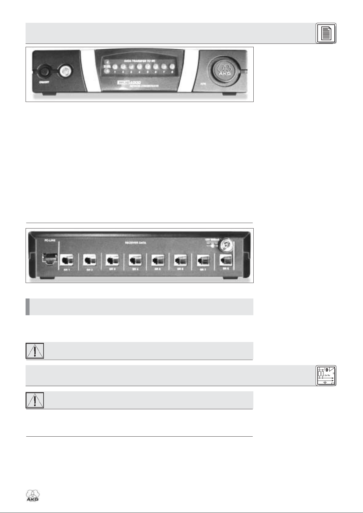
2.4.1 Frontplatte
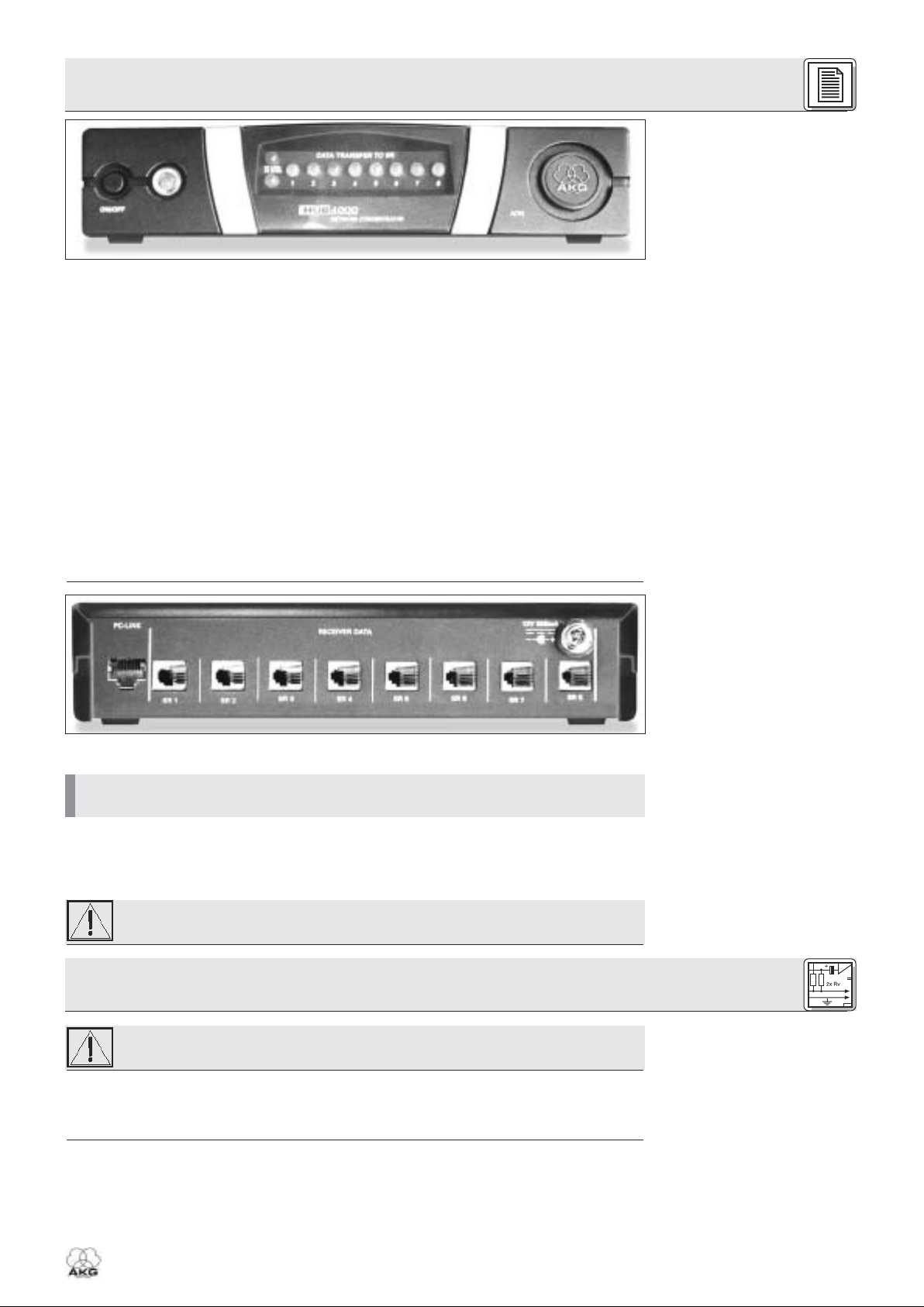
Fig. 1: Frontplatte des HUB 4000
Siehe Fig. 1.
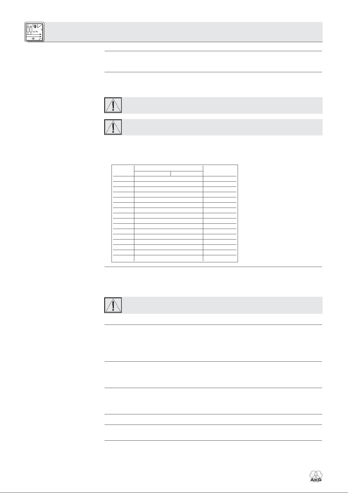
2.4.2 Rückseite
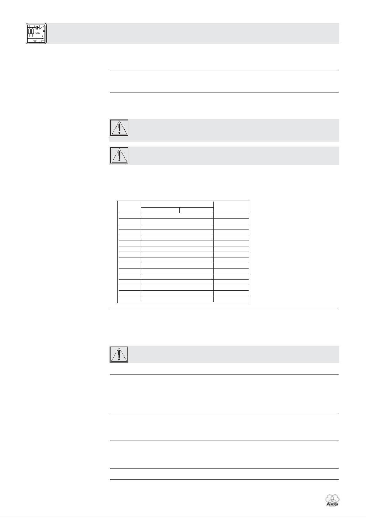
Fig. 2: Rückseite des HUB 4000
Siehe Fig. 2.
Hinweis:
Warnung!
Wichtig!
3.1 Datenverbindungen
3.1.1 Direkte Verbindung zum
PC
Siehe Fig. 4.
3.1.2 Verbindung zum PC via
Ethernet-Hub
Siehe Fig. 5.
ON/OFF: Ein/Ausschalttaste mit Kontroll-LED. Wenn das Gerät eingeschaltet ist, leuchtet die Kontroll-
LED grün.
PC LINK: Diese grüne LED leuchtet konstant, wenn das Gerät an ein Ethernet-Netzwerk angeschlossen
ist.
PC DATA: Diese grüne LED blinkt, wenn das Gerät Daten empfängt oder sendet.
DATA TRANSFER TO SR 1-8: Diese blauen LEDs zeigen den Datenaustausch zwischen dem HUB 4000
und den angeschlossenen Empfängern SR 4000 an. Jedem Datenanschluss SR 1 bis SR 8 an der
Rückseite des Geräts ist eine LED zugeordnet.
Jede LED zeigt folgende Betriebszustände an:
LED blinkt: Zwischen dem entsprechenden Datenanschluss am HUB 4000 und dem angeschlossenen Empfänger SR 4000 werden Daten ausgetauscht.
LED blinkt langsam (ca. 1 Mal in 3 Sekunden): Es treten Kommunikationsprobleme zwischen dem
entsprechenden Datenanschluss am HUB 4000 und dem zugeordneten Empfänger auf. (Hard- oder
Softwarefehler, Datenkabel defekt o.ä.)
LED dunkel: Am entsprechenden Datenanschluss ist kein Empfänger angeschlossen oder die
Verbindung wurde getrennt.
ADR: Unter der Abdeckung mit dem AKG-Logo befindet sich eine Gruppe von 4 DIP-Schaltern zum
Einstellen der IP-Adresse des Geräts.
PC LINK: RJ 45-Buchse zum Anschluss des Verbindungskabels zum PC.
Das Verbindungskabel ist nicht im Lieferumfang enthalten. Wenn Sie das Gerät direkt an einen PC
anschließen, benötigen Sie ein ausgekreuztes Netzwerkkabel. Wenn Sie das Gerät an ein StandardEthernet-Hub anschließen, benötigen Sie ein nicht ausgekreuztes Netzwerkkabel.
RECEIVER DATA SR 1 - SR 8: RJ 11-Buchsen zum Anschluss von bis zu 8 Empfängern SR 4000.
12 V/500 mA: Verschraubbare DC-Eingangsbuchse zum Anschluss des mitgelieferten Netzgeräts (12 V
DC, 500 mA).
Betreiben Sie das Gerät ausschließlich mit dem mitgelieferten Netzgerät mit einer
Ausgangsspannung von 12 V DC, 500 mA. Andere Stromarten und Spannungen könnten
das Gerät ernsthaft beschädigen!
Bevor Sie das Gerät in Betrieb nehmen, kontrollieren Sie, ob die am mitgelieferten Netzgerät
angegebene Netzspannung mit der Netzspannung am Einsatzort übereinstimmt. Der Betrieb
des Netzgeräts an einer anderen Netzspannung kann zu Schäden am Gerät führen.
1. Wenn Sie das Gerät direkt mit einem PC verbinden wollen, benötigen Sie ein ausgekreuztes
Netzwerkkabel.
2. Verbinden Sie die PC LINK-Buchse am HUB 4000 mit dem Netzwerkeingang am PC oder an der
Ethernet-Karte. (Näheres dazu entnehmen Sie bitte dem Handbuch des PCs.)
Ein HUB 4000 erlaubt Ihnen, bis zu 8 Empfänger SR 4000 von einem PC aus zu steuern. Mittels eines
oder mehrerer handelsüblicher Ethernet-Hubs können Sie mehrere HUB 4000 kaskadieren und ebenfalls
vom PC aus steuern. Wie viele Empfänger Sie tatsächlich am PC steuern können, wird letztlich von der
Größe und Auflösung des Bildschirms abhängen.
3
HUB 4000
2 Beschreibung
3 Inbetriebnahme
3.1.3 Empfänger anschließen
Siehe Fig. 4 oder 5.
3.2 IP-Adresse(n) vergeben
Siehe Fig. 6.
Wichtig!
Wichtig!
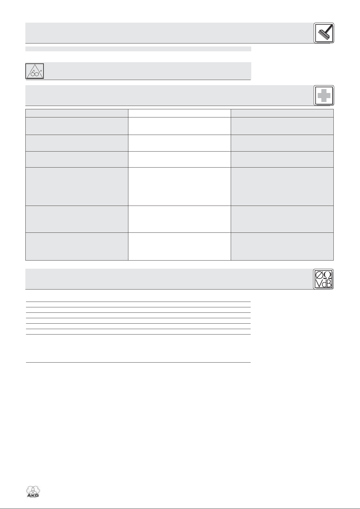
Siehe Tabelle 1.
Tabelle 1: IP-Adressen für 16 Hubs.
3.2.1 IP-Adressen einstellen
Siehe Tabelle 1.
Wichtig!
3.3 Netzanschluss
Siehe Fig. 4.
3.4 Ein- und Ausschalten
3.5 PC konfigurieren
3.6 Hubs testen
4
HUB 4000
1. Verbinden Sie das Ethernet-Hub entsprechend den Anweisungen im Handbuch des Ethernet-Hubs
und/oder PCs mit dem PC.
2. Stecken Sie an die PC LINK-Buchse jedes HUB 4000 ein nicht ausgekreuztes Netzwerkkabel an.
3. Stecken Sie das andere Ende jedes Netzwerkkabels an einen Ausgang des(der) Ethernet-Hubs an.
1. Verwenden Sie ausschließlich die mitgelieferten Datenkabel mit RJ 11-Steckern.
2. Verbinden Sie die DATA-Buchse an jedem Empfänger SR 4000 mit einer der RECEIVER DATABuchsen SR 1 bis SR 8 am HUB 4000.
• Jedes Gerät im Netzwerk benötigt eine eigene, eindeutige IP-Adresse.
• Die werksseitig eingestellte IP-Adresse des HUB 4000 lautet 192.168.0.4. Die entsprechende
Kombination der ADR-DIP-Schalter ist "1111".
Bevor Sie das Gerät mit dem Stromnetz verbinden, vergewissern Sie sich, dass die IPAdresse (ADR-Kombination) des Geräts mit keiner anderen bereits vergebenen IPAdresse innerhalb des Netzwerks übereinstimmt. Mehrfach vergebene IP-Adressen verursachen Probleme bei der Datenübertragung.
Wenn Sie mehrere HUB 4000 kaskadieren, achten Sie darauf, den einzelnen Hubs aufeinanderfolgende IP-Adressen in aufsteigender Reihenfolge zuzuordnen, um sicherzustellen, dass alle HUB 4000 vom PC richtig erkannt und gesteuert werden.
• Sie können die IP-Adresse jenes HUB 4000, der direkt mit dem PC verbunden ist (Hub Nr. 1) zwischen
192.168.0.4 und 192.168.0.19 frei wählen. Vergeben Sie an den jeweils nächsten HUB 4000 in Ihrer
Kette die jeweils nächsthöhere IP-Adresse gemäß Tabelle 1. Geben Sie die gewählte IP-Adresse des
ersten HUB 4000 auch im Steuerprogramm MCS 4000 ein, damit das Programm die Hubs richtig
ansteuern kann.
1. Nehmen Sie die Abdeckung der ADR-Schaltergruppe ab.
2. Kontrollieren Sie, ob die eingestellte IP-Adresse bereits an ein anderes Gerät im Netzwerk vergeben
ist.
3. Wenn die eingestellte IP-Adresse bereits an ein anderes Gerät im Netzwerk vergeben ist, stellen Sie
eine neue, noch nicht vergebene, IP-Adresse ein.
Wenn Sie eine neue IP-Adresse eingestellt haben, schalten Sie das Gerät aus und wieder
ein. Die neue Adresse wird erst dann wirksam, wenn Sie das Gerät wieder einschalten.
4. Stecken Sie die Abdeckung wieder auf die ADR-Schaltergruppe auf.
1. Kontrollieren Sie, ob die am mitgelieferten Netzgerät angegebene Netzspannung mit der
Netzspannung am Einsatzort übereinstimmt. Der Betrieb des Netzgeräts an einer anderen
Netzspannung kann zu irreparablen Schäden am Gerät führen.
2. Stecken Sie das Versorgungskabel des mitgelieferten Netzgeräts an die 12 V 500 mA-Buchse an der
Rückseite des HUB 4000 an und schrauben sie den Stecker fest.
3. Stecken Sie das Netzkabel des Netzgeräts an eine geeignete Netzsteckdose an.
1. Drücken Sie die ON/OFF-Taste, um das Gerät einzuschalten.
Die Kontroll-LED neben der ON/OFF-Taste leuchtet auf, die blauen DATA TRANSFER-LEDs leuchten
von innen nach außen auf und erlöschen. Damit ist das Gerät initialisiert und betriebsbereit.
2. Zum Ausschalten drücken Sie nochmals die ON/OFF-Taste.
Achten Sie darauf, der Netzwerkkarte des PCs, an die Sie den/die HUB 4000 angeschlossen haben, eine
eindeutige IP-Adresse zuzuteilen, die an keinem der angeschlossenen HUB 4000 eingestellt ist, jedoch
im selben Netzwerksegment liegt, am besten 192.168.0.1. Die Subnetzmaske (subnet mask) des HubNetzwerksegments ist immer 255.255.255.0.
Verwenden Sie zum Testen der Hubs den Befehl ping <ip-adresse>, z. B. ping 192.168.0.4.
3 Inbetriebnahme
Hub Nr. Positionen der ADR-Schalter IP-Adresse
0 … unten 1 … oben
1 1111 192.168.0.4
2 1110 192.168.0.5
3 1101 192.168.0.6
4 1100 192.168.0.7
5 1011 192.168.0.8
6 1010 192.168.0.9
7 1001 192.168.0.10
8 1000 192.168.0.11
9 0111 192.168.0.12
10 0110 192.168.0.13
11 0101 192.168.0.14
12 0100 192.168.0.15
13 0011 192.168.0.16
14 0010 192.168.0.17
15 0001 192.168.0.18
16 0000 192.168.0.19
3.7 Betrieb des Netzwerks
Wichtig!
Wichtig!
Zum Steuern des gesamten Netzwerks (Hubs und angeschlossene Empfänger) vom PC aus benötigen
Sie die optionale Software MCS 4000. Lesen Sie dazu im MCS 4000 Handbuch nach.
1. Ziehen Sie den Netzstecker aus der Steckdose.
2. Reinigen Sie die Oberflächen des Gerätes mit einem mit Wasser befeuchteten, aber nicht nassen
Tuch.
Verwenden Sie keinesfalls scharfe oder scheuernde Reinigungsmittel sowie keine, die
Alkohol oder Lösungsmittel enthalten, da diese den Lack sowie die Kunststoffteile
beschädigen könnten.
5
HUB 4000
3 Inbetriebnahme
4 Reinigung
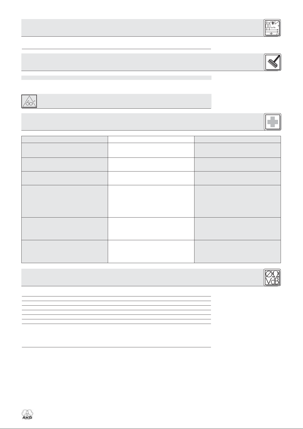
5 Fehlerbehebung
Alle LEDs bleiben nach dem Einschalten
dunkel.
PC LINK-LED bleibt nach dem Einschalten
dunkel.
DATA TRANSFER TO SR-LED(s) bleibt
(bleiben) dunkel.
DATA TRANSFER TO SR-LED(s) leuchtet
(leuchten) konstant.
DATA TRANSFER TO SR-LEDs blinken ca.
alle 2 Sekunden von innen nach außen.
POWER-, PC LINK- und PC DATA-LED
leuchten nach dem Einschalten konstant.
• Netzgerät ist nicht an HUB 4000 bzw.
Netzsteckdose angeschlossen.
• HUB 4000 ist nicht an PC/EthernetKarte/Ethernet-Hub angeschlossen.
• Kein Empfänger angeschlossen.
1. Datenkabel während Datenübertragung
abgezogen.
2. Datenkabel defekt.
• Interner Fehler.
• Interner Fehler.
• Netzgerät an HUB 4000 und Netz anstecken.
• HUB 4000 an PC/Ethernet-Karte/EthernetHub anschließen.
• Empfänger anschließen.
1. HUB 4000 ausschalten, Datenkabel anstecken, HUB 4000 einschalten.
2. HUB 4000 ausschalten, Kabel ersetzen,
HUB 4000 einschalten.
Falls der Fehler wieder auftritt, wenden Sie
sich an Ihre AKG-Servicestelle.
• Gerät ausschalten, 10 Sekunden warten,
Gerät wieder einschalten.
Falls der Fehler wieder auftritt, wenden Sie
sich an Ihre AKG-Servicestelle.
• Gerät ausschalten, 10 Sekunden warten,
Gerät wieder einschalten.
Falls der Fehler wieder auftritt, wenden Sie
sich an Ihre AKG-Servicestelle.
Fehler Mögliche Ursache Behebung
6 Technische Daten
Stromversorgung 12 V DC ±2 V
Stromverbrauch 65 mA ±20 mA
Umgebungstemperatur -10°C bis 60°C
Buchsen zum Anschluss der SR 4000 RJ11
Ethernet Anschluß RJ45
Abmessungen 200 x 190 x 44 mm
Gewicht ca. 970g
Dieses Gerät entspricht folgenden europäischen Normen:
EN 300422-2 V1.1.1
EN 301489-9 V1.3.1
EN 60065:2002
1 Safety and Environment
1.1 Safety
1.2 Environment
2.1 Introduction
Refer to figs. 3.1 and 3.2. See
SR 4000 manual for details.
2.2 Unpacking
2.3 Optional Accessories
6
HUB 4000
1. Do not spill any liquids on the equipment and do not drop any objects through the ventilation slots in
the equipment.
2. The equipment may be used in dry rooms only.
3. The equipment may be opened, serviced, and repaired by authorized personnel only. The equipment
contains no user-serviceable parts.
4. Before connecting the equipment to power, check that the AC mains voltage stated on the supplied
power supply is identical to the AC mains voltage available where you will use the equipment.
5. Operate the equipment with the included power supply with an output voltage of 12 VDC only. Using
adapters with an AC output and/or a different output voltage may cause serious damage to the unit.
6. If any solid object or liquid penetrates into the equipment, shut down the sound system immediately.
Disconnect the power supply from the power outlet immediately and have the equipment checked by
AKG service personnel.
7. If you will not use the equipment for a long period of time, disconnect the power supply from the
power outlet. Please note that the equipment will not be fully isolated from power when you set the
power switch to OFF.
8. Do not place the equipment near heat sources such as radiators, heating ducts, or amplifiers, etc. and
do not expose it to direct sunlight, excessive dust, moisture, rain, mechanical vibrations, or shock.
9. To avoid hum or interference, route all audio lines, particularly those connected to the microphone
inputs, away from power lines of any type. If you use cable ducts, be sure to use separate ducts for
the audio lines.
10.Clean the equipment with a moistened (not wet) cloth only. Be sure to disconnect the power supply
from the power outlet before cleaning the equipment! Never use caustic or scouring cleaners or cleaning agents containing alcohol or solvents since these may damage the enamel and plastic parts.
11.Use the equipment for the applications described in this manual only. AKG cannot accept any liability for damages resulting from improper handling or misuse.
1. The power supply will draw a small amount of current even when the equipment is switched off. To
save energy, disconnect the power supply from the power outlet if you will leave the equipment
unused for a long period of time.
2. When scrapping the equipment, separate the case, circuit boards, and cables, and dispose of all components in accordance with local waste disposal rules.
3. The packaging of the equipment is recyclabe. To dispose of the packaging, make sure to use a collection/recycling system provided for that purpose and observe local legislation relating to waste disposal and recycling.
Thank you for purchasing an AKG product. This Manual contains important instructions for setting up and
operating your equipment. Please take a few minutes to read the instructions below carefully before
operating the equipment. Please keep the Manual for future reference. Have fun and impress your audience!
The HUB 4000 is an Ethernet hub designed by AKG with network I/Os for controlling up to eight SR 4000
receivers from a single computer. The required optional MCS 4000 software runs under Mac OS,
Windows, and LINUX. (For detailed system requirements, refer to the MCS 4000 manual.)
For larger systems with more than eight channels, you can use commercial Ethernet hubs to daisy-chain
the required number of HUB 4000s.
You can use the HUB 4000 as a standalone unit or install it in a 19" rack using the supplied rack mounting kit.
Check that the packaging contains all of the components listed above. Should anything be missing,
please contact your AKG dealer.
2 Description
1 HUB 4000
Ethernet hub
1 in-line power supply (if
checked on the packaging)
8 data cables 1 rack mounting kit
MCS 4000
control software
2.4 Controls
2.4.1 Front Panel
Fig. 1: Front panel controls.
Refer to fig. 1.
2.4.2 Rear Panel
Fig. 2: HUB 4000 rear panel.
Refer to fig. 2.
Note:
Warning!
Important!
3.1 Data Connections
3.1.1 Direct Connection to the
Computer
Refer to fig. 4.
3.1.2 Connecting to the
Computer via an Ethernet Hub
Refer to fig. 5.
ON/OFF: Switches power to the unit on and off. The status LED next to the ON/OFF key will be lit green
to indicate power is on.
PC LINK: This green LED will be lit constantly to indicate the unit is connected to an Ethernet network.
PC DATA: This green LED will flash to indicate the unit is receiving or sending data.
DATA TRANSFER TO SR 1-8: These blue LEDs indicate the status of data exchange between the
HUB 4000 and the SR 4000 receivers connected to it. Each LED is assigned to one of the rear panel
SR 1 through SR 8 data ports.
Each LED indicates the following conditions:
LED flashing: Data is being exchanged between the assigned data port on the HUB 4000 and the
connected SR 4000 receiver.
LED flashing slowly (approx. once every 3 seconds): There is a communication problem between the
assigned data port on the HUB 4000 and the connected SR 4000 receiver (hard or software error,
defective data cable, etc.).
LED is dark: No receiver is connected to the assigned data port or the connection has been interrupted.
ADR: Located beneath the cover with the AKG logo is a bank of four DIP switches for setting the IP
address of the HUB 4000.
PC LINK: This RJ 45 socket accepts the connecting cable to the computer.
The connecting cable is not supplied with the unit. To connect the unit directly to a computer, use a
crossover Ethernet cable. To connect the unit to a standard Ethernet hub, use a straight-through
Ethernet cable.
RECEIVER DATA SR 1 - SR 8: RJ 11 sockets for connecting up to eight SR 4000 receivers.
12 V/500 mA: Locking DC input for connecting the included power supply (12 VDC, 500 mA).
Operate the equipment with the included power supply with an output voltage of 12 VDC,
500 mA only. Using adapters with an AC output and/or a different output voltage may
cause serious damage to the unit.
Prior to setting up the unit, check that the AC mains voltage stated on the included power
supply is identical to the AC mains voltage available where you will use your system.
Using the power supply with a different AC voltage may cause damage to the unit.
1. Use a crossover Ethernet cable to connect the HUB 4000 to a computer.
2. Connect the PC LINK socket on the HUB 4000 to a network input on the computer or Ethernet card.
(For details refer to the manual of your computer.)
A single HUB 4000 allows you to control up to eight SR 4000 receivers from a computer. You can use
one or more commercial Ethernet hubs to daisy-chain several HUB 4000s and control the entire setup
from the computer. The number of receivers you can actually control on your computer will ultimately
depend on the size and resolution of your monitor.
1. Connect the Ethernet hub to the computer referring to the manual(s) of the Ethernet hub and/or computer.
2. Plug a straight-throughEthernet cable into the PC LINK socket of each HUB 4000.
7
HUB 4000
2 Description
3 Setting Up
3.1.3 Connecting Receivers
Refer to fig. 4 or 5.
3.2 Assigning IP Addresses
Refer to fig. 6.
Important!
Important!
Refer to Table 1.
Table 1: IP addresses for 16 hubs.
3.2.1 Setting IP addresses
Refer to Table 1.
Important!
3.3 Connecting to Power
Refer to fig. 4.
3.4 Powering Up/Down
3.5 Setting Up the Computer
3.6 Testing the Hubs
3.7 Operating the Network
8
HUB 4000
3. Plug the other end of each network cable to an unused output on (one of) your Ethernet hub(s).
1. Be sure not to use any cables other than the supplied data cables with RJ 11 connectors.
2. Connect the DATA socket on each SR 4000 receiver to one of the RECEIVER DATA sockets SR 1 to
SR 8 on the HUB 4000 rear panel.
• Each unit within the network needs its own, unambiguous IP address.
• The IP address of each HUB 4000 is factory-set to 192.168.0.4. The related combination of the ADR
DIP switches is "1111".
Before connecting the unit to power, check that the IP address (ADR combination) of the
unit is not identical to any other IP address previously assigned within the network. IP
addresses assigned to multiple units may cause data transmission problems.
If you daisy-chain several HUB 4000s, remember to assign to the hubs consecutive IP
addresses in ascending order to make sure the computer will correctly identify and control all HUB 4000s.
• You may assign any IP address between 192.168.0.4 and 192.168.0.19 to the HUB 4000 directly connected to the computer (hub no. 1). Assign the next higher IP address to the next HUB 4000 in your
chain referring to Table 1. Enter the selected IP address of the first HUB 4000 in the MCS 4000 control program to enable the program to control the hubs correctly.
1. Remove the cover of the ADR switch bank.
2. Check that the current IP address has not been assigned to any other unit within the network yet.
3. If the current IP address has been assigned to another unit within the network, set a new IP address
that has not been assigned to any other unit.
Upon having set a new IP address, switch power to the unit off and back on. The new IP
address will not become active before you have switched power back on.
4. Replace the ADR switch bank cover.
1. Check that the AC mains voltage stated on the included power supply is identical to the AC
mains voltage available where you will use your system. Using the power supply with a different AC voltage may cause damage to the unit.
2. Plug the DC cable on the included power supply into the 12 V/500 mA socket on the HUB 4000 rear
panel and screw down the DC connector.
3. Plug the power cable on the power supply into a convenient power outlet.
1. To switch power to the unit on, press the ON/OFF key.
The status LED next to the ON/OFF key will be lit, the blue DATA TRANSFER LEDs will illuminate starting from the center and extinguish to indicate the unit is initialized and ready to operate.
2. To switch power to the unit off, press the ON/OFF key again.
Make sure to assign an unambiguous IP address to the network card on the computer to which you connected the HUB 4000(s). Select a network card address that differs from any HUB 4000 IP address in the
network but is within the same network segment, preferably 192.168.0.1. The subnet mask of the hub
network segment is always 255.255.255.0.
To test the hubs, use the ping <ip address> command, e.g., ping 192.168.0.4.
To control the entire network (hubs and connected receivers) from your computer, you will need the
optional MCS 4000 software. Refer to the MCS 4000 manual.
3 Setting Up
Hub no. ADR switch positions IP address
0 .. down 1 … up
1 1111 192.168.0.4
2 1110 192.168.0.5
3 1101 192.168.0.6
4 1100 192.168.0.7
5 1011 192.168.0.8
6 1010 192.168.0.9
7 1001 192.168.0.10
8 1000 192.168.0.11
9 0111 192.168.0.12
10 0110 192.168.0.13
11 0101 192.168.0.14
12 0100 192.168.0.15
13 0011 192.168.0.16
14 0010 192.168.0.17
15 0001 192.168.0.18
16 0000 192.168.0.19
9
HUB 4000
4 Cleaning
Important!
Important!
1. Disconnect the power supply from the power outlet.
2. Use a cloth moistened (not wet!) with water to clean the surfaces of the equipment.
Never use caustic or scouring cleaners or cleaning agents containing alcohol or solvents
since these may damage the enamel or plastic parts.
Power supply 12 VDC ±2 V
Current consumption 65 mA ±20 mA
Ambient temperature -10°C to +60°C
Connectors for SR 4000 receivers RJ11
Ethernet connector RJ45
Size 200 x 190 x 44 mm (7.8 x 7.5 x 1.7 in.)
Weight approx. 970g (2.2 lbs.)
This equipment fulfills the following European standards:
EN 300422-2 V1.1.1
EN 301489-9 V1.3.1
EN 60065:2002
5 Troubleshooting
All LEDs remain dark on powering up.
PC LINK LED remains dark
on powering up.
DATA TRANSFER TO SR LED(s)
remain(s) dark
DATA TRANSFER TO SR LED(s)
is (are) lit constantly.
DATA TRANSFER TO SR LEDs flash
from center outward
approx. every 2 seconds.
POWER, PC LINK, and PC DATA LEDs are
lit constantly after power-up.
• Power supply is not connected to
HUB 4000 and/or power outlet.
• HUB 4000 is not connected to
computer/Ethernet card/Ethernet hub.
• No receiver connected.
1. Data cable(s) disconnected during data
transfer.
2. Data cable(s) defective.
• Internal error.
• Internal error.
• Connect power supply to HUB 4000
and/or power outlet.
• Connect HUB 4000 to computer/Ethernet
card/Ethernet hub.
• Connect receiver(s).
1. Switch HUB 4000 OFF, connect data
cable, switch HUB 4000 back ON.
2. Switch HUB 4000 OFF, replace data cable,
switch HUB 4000 back ON.
Should the problem persist, contact your
nearest AKG Service Center.
• Switch unit OFF, wait for 10 seconds,
switch unit back ON.
Should the problem persist, contact your
nearest AKG Service Center.
• Switch unit OFF, wait for 10 seconds,
switch unit back ON.
Should the problem persist, contact your
nearest AKG Service Center.
Problem Possible Cause Remedy
6 Specifications
1 Sécurité et environnement
1.1 Sécurité
1.2 Environnement
2.1 Introduction
Voir Fig. 3.1 et 3.2. Pour plus de
détails, voir la notice du SR 4000.
2.2 Fournitures d’origine
2.3 Accessoires optionnels
10
HUB 4000
1. Faites attention de ne pas renverser de liquide sur l’appareil et à ce que rien ne tombe à l’intérieur par
les fentes d’aération.
2. Cet appareil ne doit en aucun cas être utilisé dans un local humide.
3. Cet appareil ne peut être ouvert, entretenu et réparé que par le personnel technique autorisé. On ne
trouve à l’intérieur du boîtier aucun élément pouvant être entretenu, réparé ou remplacé par un profane.
4. Avant de mettre l’appareil en service, vérifiez si la tension de service indiquée sur le bloc secteur fourni correspond bien à la tension secteur sur le lieu d’utilisation.
5. N’utilisez jamais l’appareil avec une alimentation autre que le bloc secteur pour courant alternatif et
tension sortie de 12 V c.c. fourni avec l’appareil. Tout autre type de courant ou de tension risqueraient
de provoquer de sérieux dégâts sur l’appareil !
6. S’il arrivait qu’un objet quelconque ou du liquide pénètre à l’intérieur de l’appareil, mettez immédiatement la chaîne hors service. Débranchez aussitôt le bloc secteur et faites réviser l’appareil par notre
service après-vente.
7. Lorsque vous avez l’intention de rester quelque temps sans utiliser l’appareil, débranchez le bloc secteur. Tant que l’adaptateur est branché sur la prise secteur, l’appareil n’est pas entièrement coupé du
secteur lorsque vous le mettez hors tension.
8. Ne placez jamais l’appareil à proximité d’une source de chaleur (radiateur, tuyaux de chauffage, amplificateurs, etc.) ni à un endroit où il risque d’être exposé directement au soleil, à une atmosphère poussiéreuse, à l’humidité, à la pluie, aux vibrations ou aux secousses.
9. Pour éviter les parasites et les interférences, posez tous les fils, en particulier ceux des entrées micro,
séparément des câbles de puissance et des lignes de secteur. En cas de pose dans un puits ou une
conduite pour câbles, les câbles de transmission devront toujours être posés dans une conduite séparée.
10.Pour nettoyer l’appareil, utilisez un chiffon légèrement humide, jamais un chiffon mouillé. N’oubliez
surtout pas de débrancher auparavant le bloc secteur ! N’utilisez jamais de produits de nettoyage
mordants ou abrasifs, non plus que des produits contenant de l’alcool ou un solvant qui risqueraient
d’abîmer la laque et les éléments en plastique.
11.N’utilisez jamais l'appareil pour une application autre que celles indiquées dans le mode d’emploi.
AKG décline toute responsabilité concernant les dégâts qui résulteraient d’une manipulation inappropriée ou d’une utilisation non conforme.
1. Le bloc secteur consomme toujours un peu de courant même lorsque l’appareil est hors tension. Pour
économiser le courant, pensez donc à débrancher le bloc secteur lorsque l’appareil restera un certain
temps sans être utilisé.
2. Si vous mettez l’appareil à la ferraille, enlevez les piles ou les accus, séparez le boîtier, l’électronique
et les câbles et éliminez les différents éléments conformément aux règlements en vigueur.
3. L'emballage est recyclable. Déposez l'emballage dans un récipient de collecte prévu à cet effet.
Nous vous remercions d’avoir choisi un produit AKG. Lisez très attentivement ce mode d’emploi avant
la mise en service de l’appareil. Conservez soigneusement le mode d’emploi pour pouvoir le consulter
lorsque vous vous posez des questions. Nous vous souhaitons beaucoup de succès.
Le HUB 4000 est un concentrateur Ethernet développé par AKG, qui permet de gérer jusqu’à 8 récepteurs SR 4000 depuis un ordinateur personnel. Le logiciel nécessaire MCS 4000, compatible Mac OS,
Windows et LINUX, est fourni séparément. (Pour les conditions exactes devant être remplies par le système, veuillez vous reporter au manuel MCS 4000.)
Pour les chaînes comportant plus de 8 canaux, il est possible de cascader le nombre de HUB 4000 voulu
à l’aide de concentrateurs Ethernet courants.
L’appareil convient aussi bien pour l’installation volante que pour le montage en rack 19", qui s’effectue
à l’aide du kit de montage 19" fourni.
Vérifiez si l’emballage contient bien tous les éléments énumérés ci-dessus. Si les fournitures ne sont pas
complètes veuillez le signaler à votre revendeur AKG.
2 Description
1 Concentrateur
Ethernet HUB 4000
1 Bloc secteur Inline (si mar-
qué d’une croix sur l’emballage)
8 Câble données
1 Kit de montage en
rack
Logiciel de pilotage
MCS 4000
 Loading...