

Page 1

WMS40
wireless microphone system
Bedienungshinweise . . . . . . . . . . . . . . . . . . S. 2
Bitte vor Inbetriebnahme des Gerätes lesen!
User Instructions . . . . . . . . . . . . . . . . . . . . p. 11
Please read the manual before using the equipment!
Mode d’emploi . . . . . . . . . . . . . . . . . . . . . . p. 20
Veuillez lire cette notice avant d’utiliser le système!
Istruzioni per l’uso . . . . . . . . . . . . . . . . . . . p. 29
Prima di utilizzare l’apparecchio, leggere il manuale!
Modo de empleo . . . . . . . . . . . . . . . . . . . . p. 38
Antes de utilizar el equipo, sírvase leer el manual!
Instruções de uso . . . . . . . . . . . . . . . . . . . p. 47
Favor leia este manual antes de usar o equipamen
to!
HT 40 handheld transmitter
Page 2
1 Sicherheit und
Umwelt
1.1 Sicherheit
1. Setzen Sie das Gerät nicht direkter
Sonneneinstrahlung, starker Staubund Feuchtigkeitseinwirkung, Regen,
Vibrationen oder Schlägen aus.
1.2 Umwelt
1. Entsorgen Sie verbrauchte Batterien
und Akkus immer gemäß den jeweils
geltenden Entsorgungsvorschriften.
Werfen Sie Batterien oder Akkus
weder ins Feuer (Explosionsgefahr)
noch in den Restmüll.
2. Wenn Sie das Gerät verschrotten, entfernen Sie die Batterien bzw. Akkus,
trennen Sie Gehäuse, Elektronik und
Kabel und entsorgen Sie alle
Komponenten gemäß den dafür geltenden Entsorgungsvorschriften.
2
2 Beschreibung
2.1 Einleitung
Vielen Dank, dass Sie sich für ein
Produkt aus dem Hause AKG entschieden haben. Bitte lesen Sie die
Bedienungsanleitung aufmerksam
durch, bevor Sie das Gerät benützen,
und bewahren Sie die Bedienungsanleitung sorgfältig auf, damit Sie jederzeit nachschlagen können. Wir wünschen Ihnen viel Spaß und Erfolg!
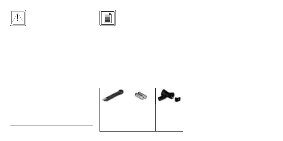
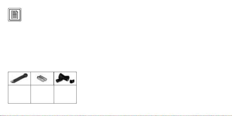
2.2 Lieferumfang
1 Handsender
HT 40
2 Batterien
1,5 V,
Größe AA
1 Stativ-
anschluss
SA 43, Farbcode-Clip,
schwarz
Kontrollieren Sie bitte, ob die Verpackung alle oben angeführten Teile enthält. Falls etwas fehlt, wenden Sie sich
bitte an Ihren AKG-Händler.
2.3 Empfohlenes Zubehör
Schaumstoff-Windschutz W 880
2.4 Beschreibung
Der Handsender HT 40 arbeitet auf einer
fixen, quarzstabilisierten Trägerfrequenz
im UHF-Trägerfrequenzbereich von 710
bis 865 MHz und ist mit einer im
Gehäuse integrierten Antenne ausgestattet.
Der mit dem Sender fix verbundene
Mikrofonkopf ist akustisch identisch mit
dem Vokalmikrofon D 880 von AKG.
Dieses Mikrofon besitzt ein eingebautes
Wind- und Popfilter zur Unterdrückung
von Pop- und Atemgeräuschen und
zeichnet sich durch geringe
Handgeräuschempfindlichkeit, gute
Page 3
Rückkopplungsunterdrückung und bril-
ON
MUTE
OFF
lante Übertragungsqualität aus.
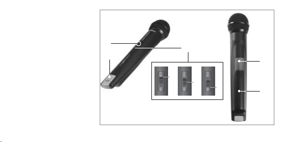
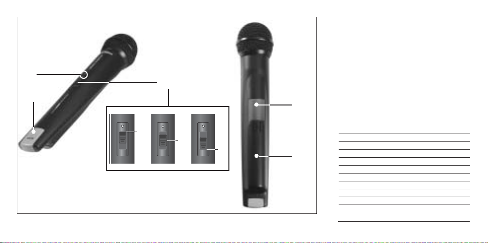
2.5 Bedienelemente (siehe Abb. 1)
1Ein/Ausschalter: Dieser
Schiebeschalter hat drei
Stellungen, die jeweils im
Sichtfenster angezeigt werden:
ON: Die Spannungsversorgung für
den Sender ist eingeschaltet.
MUTE: Das vom Mikrofonkopf
kommende Audiosignal ist
stummgeschaltet, Spannungsversorgung und HF-Trägerfrequenz bleiben jedoch eingeschaltet. Dadurch wird der
Empfänger trotz abgeschaltetem Mikrofon nicht durch andere
Sender gestört.
OFF: Die Spannungsversorgung für
den Sender ist ausgeschaltet.
2 Kontroll-LED: Diese LED zeigt den
Ladezustand der Batterien an.
2
3
Abb. 1: Bedienelemente HT 40
1
5
4
3
Page 4
LED leuchtet beim Einschalten kurz
auf und erlischt wieder: Batterien in
Ordnung.
LED leuchtet: Batterien in ca. 50
Minuten erschöpft.
3 Farbcode: Die Farbe dieses
Kunststoffclips entspricht der
Trägerfrequenz Ihres Senders.
Empfänger mit derselben Trägerfrequenz sind mit derselben Farbe
gekennzeichnet (s. Kapitel 2.6
Farbcode-Tabelle). Der Farbcodeclip des HT 40 ist abnehmbar und
kann durch den mitgelieferten
schwarzen Clip ersetz werden.
4 Batteriefachdeckel: Siehe Ka-
pitel 3.2 Batterien einlegen.
5Trägerfrequenzetikette: Ober-
halb des Batteriefachs ist eine
Haftetikette mit der Trägerfrequenz
des Senders angebracht.
4
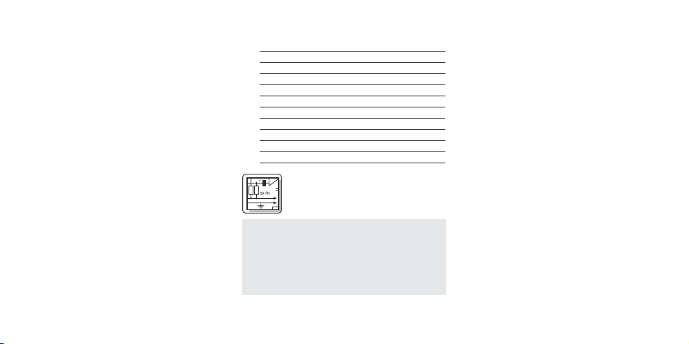
2.6 Farbcode-Tabelle
Frequenz Farbe
US54: 710.400 MHz rotbraun
US58: 734.600 MHz purpur
KR3: 745.650 MHz mintgrün
KR4: 750.900 MHz dunkelgrau
EU62: 802.525 MHz bordeauxrot
EU63: 812.800 MHz gelb
UK69A: 854.900 MHz violett
UK69B: 858.200 MHz grün
ISM1: 863.100 MHz melonengelb
ISM2: 864.375 MHz grau
3 Inbetriebnahme
Wichtig: Bevor Sie Ihr WMS 40 in
Betrieb nehmen, kontrollieren Sie, ob
Sender und Empfänger auf derselben
Frequenz arbeiten. Am leichtesten
können Sie dies anhand des
Farbcodes überprüfen.
3.1 Empfänger positionieren
Reflexionen des Sendersignals an
Metallteilen, Wänden, Decken, etc. oder
Abschattungen durch menschliche
Körper können das direkte Sendersignal
schwächen bzw. auslöschen.
Stellen Sie den Empfänger daher wie
folgt auf:
1. Positionieren Sie den Empfänger
immer in der Nähe des
Aktionsbereiches (Bühne), achten Sie
jedoch auf einen Mindestabstand
zwischen Sender und Empfänger von
3 m bis optimal 5 m.
2. Voraussetzung für optimalen
Empfang ist Sichtverbindung zwischen Sender und Empfänger.
3. Positionieren Sie den Empfänger in
einem Abstand von mehr als
1,5 m von großen metallenen Gegenständen, Wänden, Bühnengerüsten,
Decken, u.ä.
Page 5
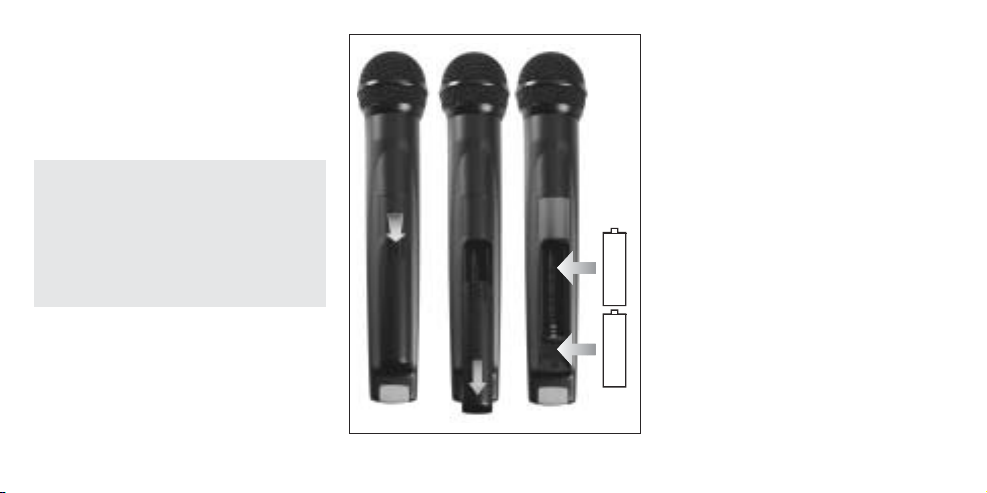
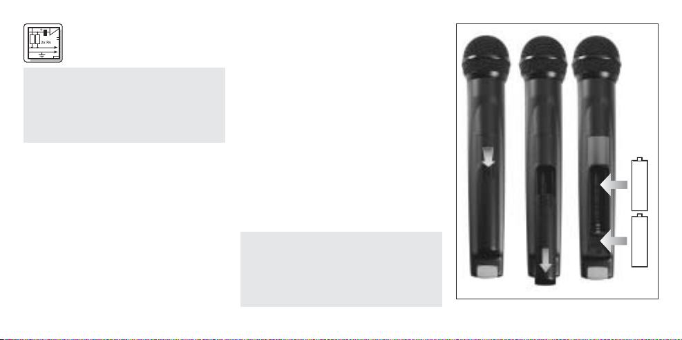
3.2 Batterien in den Sender einlegen und testen (siehe Abb. 2)
1. Drücken Sie den Schnapphaken am
Batteriefachdeckel (4) nach unten.
2. Ziehen Sie den Batteriefachdeckel (4)
nach unten vom Sender ab.
Wichtig: Der Schaumstoffpolster an der
Innenseite des Batteriefachdeckels
fixiert die Batterie in ihrer Position.
Entfernen Sie den Schaumstoffpolster nicht, da die Batterie ansonsten nicht richtig im Batteriefach
fixiert ist und Klappergeräusche verursachen kann.
3. Legen Sie die mitgelieferten Batterien
in das Batteriefach ein und achten
Sie dabei auf die richtige Polarität der
Batterien.
Wenn Sie die Batterien falsch einlegen, wird der Sender nicht mit Strom
versorgt.
Abb. 2: Batterien einlegen
2 x
1. 5 V
+
–
+
–
4. Schalten Sie den Sender ein, indem
Sie den Ein/Aus-Schalter (1) auf “ON”
stellen.
Die Kontroll-LED (2) blitzt kurz auf.
Wenn die Batterien in gutem Zustand
sind, erlischt die Kontroll-LED (2) wieder.
Wenn die Kontroll-LED (2 zu leuchten
beginnt, sind die Batterien in ca. 50
Minuten erschöpft. Tauschen Sie die
Batterien möglichst bald gegen frische aus.
Wenn die Kontroll-LED (2) nicht aufblitzt, sind die Batterien erschöpft.
Legen Sie neue Batterien ein.
5. Schließen Sie das Batteriefach,
indem Sie den Batteriefachdeckel (4)
von unten auf das Batteriefach aufschieben, bis der Schnapphaken einrastet.
3.3 Sender in Betrieb nehmen
1. Schalten Sie den Empfänger ein und
5
Page 6
kontrollieren Sie die Stellung des
VOLUME-Reglers:
Empfänger mit Mikrofoneingang
verbunden = linker Anschlag,
Empfänger mit Line-Eingang ver-
bunden = rechter Anschlag.
2. Schalten Sie den Handsender ein,
indem Sie Sie den Ein/Aus-Schalter
(1) auf ”ON” stellen.
Da der Handsender HT 40 speziell für
den eingebauten Mikrofonkopf ausgelegt ist, ist keine Pegeleinstellung
am Handsender erforderlich. Der
Handsender besitzt daher auch keinen Pegel- oder ”Gain”-Regler.
3. Schalten Sie Ihre PA-Anlage bzw.
Ihren Verstärker ein.
4. Sprechen oder singen Sie in das
Mikrofon und stellen Sie die
Lautstärke der PA-Anlage bzw. des
Verstärkers wie in deren Bedienungsanleitung beschrieben oder nach
Gehör ein.
6
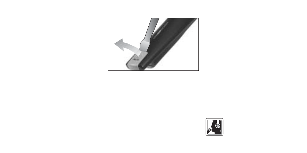
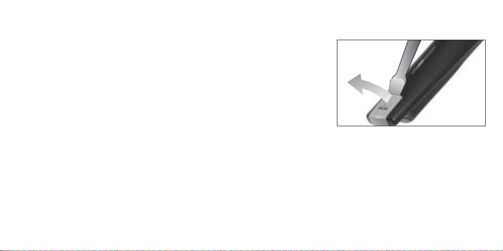
3.4 Farbcode-Clip tauschen
Abb. 3: Farbcode-Clip tauschen
1. Heben Sie den Farbcode-Clip mit
einem Schraubenzieher am oberen
Ende an.
2. Ziehen Sie den Farcode-Clip ab.
3. Stecken Sie den mitgelieferten
schwarzen Clip auf den Handsender
so auf, dass er hörbar einrastet.
3.5 Vor dem Soundcheck
1. Schreiten Sie den Bereich ab, in dem
(s. Abb. 3)
Sie den Sender einsetzen werden.
Achten Sie dabei auf Stellen, wo die
Feldstärke absinkt und daher der
Empfang kurzzeitig gestört wird
(“Dropouts”).
Solche Dropouts können Sie beheben, indem Sie den Empfänger
anders positionieren. Hat dies keinen
Erfolg, vermeiden Sie diese kritischen
Stellen.
2. Wenn am Empfänger die RF-LED
erlischt, bedeutet dies, dass kein
Signal empfangen wird oder der
Squelch aktiv ist.
Schalten Sie den Sender ein und/oder
gehen Sie näher zum Empfänger, bis
die RF-LED am Empfänger aufleuchtet.
4 Mikrofontechnik
Ein Gesangsmikrofon bietet
Ihnen viele Möglichkeiten, den
Page 7
Klang Ihrer Stimme, wie er durch die
Beschallungsanlage wiedergegeben
wird, zu gestalten.
Beachten Sie bitte die folgenden
Hinweise, um Ihren Handsender HT 40
optimal einsetzen zu können.
4.1 Besprechungsabstand und
Naheffekt
Grundsätzlich wird Ihre stimme umso
voller und weicher wiedergegeben, je
kürzer der Abstand zwischen den Lippen
und dem Mikrofon ist, während bei
größerer Mikrofondistanz ein halligeres,
entfernteres Klangbild zustande kommt,
da die Akustik des Raumes stärker zur
Geltung kommt.
Sie können daher Ihre Stimme aggressiv,
neutral oder einschmeichelnd klingen
lassen, indem Sie den Mikrofonabstand
verändern.
Der Naheffekt tritt im unmittelbaren
Nahbereich der Schallquelle (weniger als
5 cm) auf und bewirkt eine starke
Betonung der Tiefen. Er verleiht Ihrer
Stimme einen voluminöseren, intimen,
bassbetonten Klang.
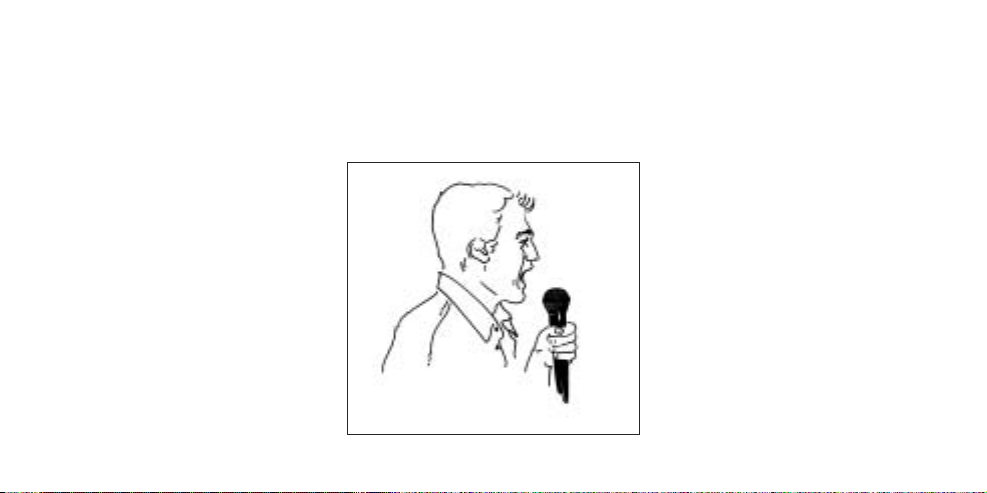
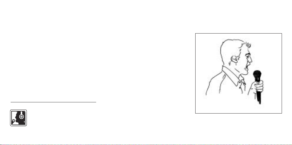
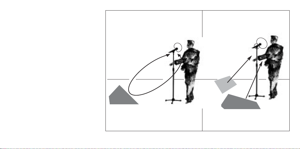
4.2 Schalleinfallswinkel (s. Abb. 4)
Abb. 4: Schalleinfallswinkel
Singen Sie seitlich auf das Mikrofon oder
über den Mikrofonkopf hinweg. So
erhalten Sie einen ausgewogenen,
naturgetreuen Klang.
Wenn Sie direkt von vorne auf das
Mikrofon singen, werden nicht nur
Atemgeräusche mitübertragen, sondern
auch Verschlusslaute (p, t) und Zischlaute (s, sch, tsch) unnatürlich hervorgehoben.
4.3 Rückkopplung (s. Abb. 5, S. 8)
Die Rückkopplung kommt dadurch
zustande, dass ein Teil des von den
Lautsprechern abgegebenen Schalls
vom Mikrofon aufgenommen und verstärkt wieder den Lautsprechern zugeleitet wird. Ab einer bestimmten
Lautstärke (der Rückkopplungsgrenze)
läuft dieses Signal gewissermaßen im
Kreis, die Anlage heult und pfeift und
kann nur durch Zurückdrehen des
7
Page 8
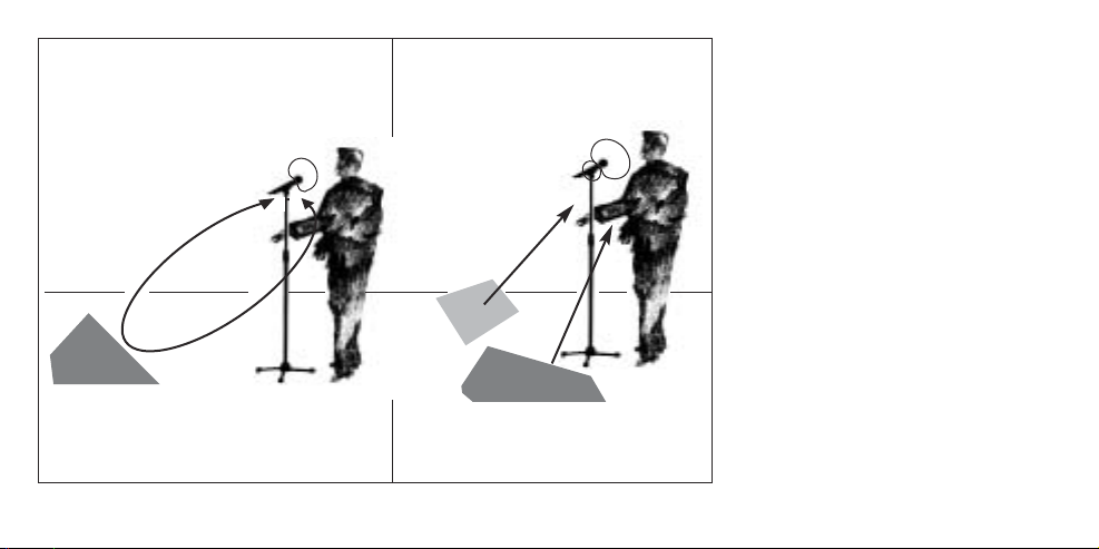
Abb. 5: Rückkopplung
8
Lautstärkereglers wieder unter Kontrolle
gebracht werden.
Um dieser Gefahr zu begegnen, hat das
Mikrofon des Handsenders HT 40 eine
supernierenförmige Richtcharakteristik.
Das bedeutet, dass es für Schall, der
von vorne einfällt (die Stimme) am empfindlichsten ist, während es auf seitlich
einfallenden Schall oder Schall, der von
hinten auftrifft (z.B. von Monitorlautsprechern), kaum anspricht.
Minimale Rückkopplungsneigung erreichen Sie, indem Sie die PALautsprecher vor den Mikrofonen (am
vorderen Bühnenrand) aufstellen.
Wenn Sie Monitorlautsprecher verwenden, lassen Sie Ihr Mikrofon nie direkt
auf die Monitore oder die PALautsprecher zeigen.
Rückkopplung kann auch durch
Resonanzerscheinungen (als Folge der
Raumakustik), besonders im unteren
Frequenzbereich, ausgelöst werden,
Page 9

also indirekt durch den Naheffekt. In diesem Fall brauchen Sie oft nur den
Mikrofonabstand zu vergrößern, um die
Rückkopplung zum Abreissen zu bringen.
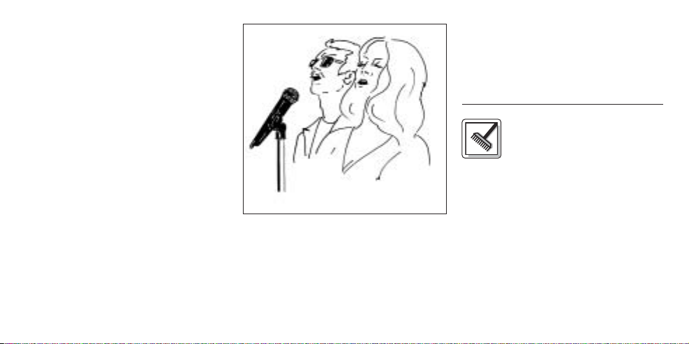
4.4 Begleitchor (s. Abb. 6)
Abb. 6: Begleitchor
1. Lassen Sie nie mehr als zwei
Personen in ein gemeinsames
Mikrofon singen.
2. Achten Sie darauf, dass der
Schalleinfallswinkel nie größer als 35°
ist.
Das Mikrofon ist für seitlich einfallenden Schall sehr unempfindlich. Wenn
die beiden VokalistInnen aus einem
größeren Winkel als 35° auf das
Mikrofon singen, müssten Sie den
Pegelregler des Mikrofonkanals so
weit aufziehen, dass die Rückkopplungsgefahr zu groß würde.
4.5 Fehlerbehebung
Hinweise zur Fehlerbehebung finden
Sie in der Bedienungsanleitung Ihres
Empfängers.
5 Reinigung
5.1 Oberflächen
Zum Reinigen der Oberflächen
des Senders verwenden Sie am besten ein
mit Wasser befeuchtetes weiches Tuch.
5.2 Innenwindschutz
1. Schrauben Sie die Gitterkappe des
Handseners gegen den Uhrzeigersinn vom Handsender ab.
2. Nehmen Sie Windschutz (Schaum-
stoffeinlage) aus der Gitterkappe heraus.
3. Waschen Sie den Windschutz in stark
verdünnter Seifenlauge.
4. Sobald der Windschutz trocken ist,
legen Sie ihn wieder in die Gitterkappe ein und schrauben Sie die
Gitterkappe im Uhrzeigersinn auf den
Handsender auf.
9
Page 10

6 Technische Daten
Trägerfrequenz 710 - 865 MHz
Audioübertragungsbandbreite 40 - 20.000 Hz
Frequenzstabilität (-10°C bis +50°C) ±15 kHz
Nennhub 15 kHz
Klirrfaktor bei 1 kHz typ. 0,8%
Kompander integriert
Signal/Rauschabstand typ. 103 dB(A)
HF-Ausgangsleistung typ. 10 mW
Stromaufnahme typ. 70 mA
Spannungsversorgung 2 x 1,5 V-Batterien Größe AA
Betriebszeit typ. 30 h
Audio-Eingangspegel für Nennhub 100 mV/1 kHz
Eingangsimpedanz 220 kΩ
Abmessungen (L x ø) 258 x 40 mm
Nettogewicht 245 g
Dieses Produkt entspricht den Normen EN60065:1998,
EN301 489-9 v.1.1.1 (09-2000) und EN300 422-2 v.1.1.1 (07-2000).
10
Modulation FM
Page 11

This equipment has been tested and
FCC Statement
found to comply with the limits for a Class
B digital device, pursuant to Parts 74, 15,
and 90 of the FCC Rules. These limits are
designed to provide reasonable protection against harmful interference in a residential installation. This equipment generates, uses, and can radiate radio frequency energy and, if not installed and
used in accordance with the instructions,
may cause harmful interference to radio
communications. However, there is no
guarantee that interference will not occur
in a particular installation. If this equipment does cause harmful interference to
radio or television reception, which can
be determined by turning the equipment
off and on, the user is encouraged to try
to correct the interference by one or more
of the following measures:
• Reorient or relocate the receiving
antenna.
• Increase the separation between the
equipment and the receiver.
• Connect the equipment into an outlet
on a circuit different from that to
which the receiver is connected.
• Consult the dealer or an experienced
radio/TV technician for help.
Shielded cables and I/O cords must be
used for this equipment to comply with
the relevant FCC regulations.
Changes or modifications not expressly
approved in writing by AKG Acoustics
may void the user’s authority to operate
this equipment.
This device complies with Part 15 of the
FCC Rules. Operation is subject to the
following two conditions: (1) this device
may not cause harmful interference, and
(2) this device must accept any interference received, including interference
that may cause undesired operation.
1 Safety and
Environment
1.1 Safety
1. Do not expose the equipment to
direct sunlight, excessive dust, moisture, rain, mechanical vibrations, or
shock.
1.2 Environment
1. Be sure to dispose of used batteries
as required by local waste disposal
rules. Never throw batteries into a fire
(risk of explosion) or garbage bin.
2. When scrapping the equipment,
remove the batteries, separate the
case, circuit boards, and cables, and
dispose of all components in accordance with local waste disposal rules.
11
Page 12
2 Description
2.1 Introduction
Thank you for purchasing an AKG
product. This Manual contains important
instructions for setting up and operating
your equipment. Please take a few
minutes to read the instructions below
carefully before operating the equip-
ment. Please keep the Manual for future
reference. Have fun and impress your
audience!
2.2 Unpacking
1 HT 40
12
Dear Customer:
Handheld
Transmitter
2 AA size
1.5 V dry
batteries
1 SA 43 stand
adapter,
black color
code clip
Check that the package contains all the
parts listed above. If anything is missing,
please contact your AKG dealer.
2.3 Optional Accessories
W 880 foam windscreen
2.4 Description
The HT 40 handheld transmitter operates on one fixed, quartz stabilized frequency in the 710 MHz to 865 MHz UHF
carrier frequency range and uses an
antenna integrated in the body.
The microphone element permanently
mounted on the transmitter is acoustically identical to the D 880 vocal microphone from AKG. This microphone features a built-in wind and pop filter to
reduce wind and breath noise and provides low handling noise sensitivity, high
gain before feedback, and brilliant sound
quality.
2.5 Controls (See fig. 1 on page 13)
1 On/Off switch: This slide switch
provides three positions indicated
in the display window:
ON: Power to the transmitter is on.
MUTE: The signal delivered by the
microphone element is muted
while power and the RF carrier
frequency remain on. This prevents the receiver from responding to interference from other
transmitters.
OFF: Power to the transmitter is off.
2 Status LED: Indicates battery status.
LED flashes momentarily upon
switching ON and extinguishes:
batteries are OK.
LED lights constantly: batteries will
be dead in about 50 minutes.
3Color Code: The color of this plastic
clip indicates the carrier frequency of
your transmitter. Receivers tuned to
the same frequency are marked with
Page 13
ON
MUTE
OFF
2
3
Fig. 1: HT 40 controls.
the same color (refer to section 2.6).
You can remove the color code clip
on the HT 40 and replace it with the
supplied black clip.
4 Battery Compartment Lid: Refer
to section 3.2.
5 Carrier Frequency Label: The
1
label above the battery compartment
indicates the carrier frequency and
5
approval marks of your transmitter.
2.6 Color Code Table
Frequency Color
US54: 710.400 MHz reddish brown
US58: 734.600 MHz purple
4
KR3: 745.650 MHz mint green
KR4: 750.900 MHz dark gray
EU62: 802.525 MHz Bordeaux red
EU63: 812.800 MHz yellow
UK69A: 854.900 MHz violet
UK69B: 858.200 MHz green
ISM1: 863.100 MHz melon yellow
ISM2: 864.375 MHz gray
13
Page 14
3 Setting Up
Important: Prior to setting up your
WMS 40, check that the transmitter
and receiver are tuned to the same
frequency. The easiest way to do this
is to compare the color codes on the
transmitter and receiver.
3.1 Placing the Receiver
Reflections off metal parts, walls, ceilings, etc. or the shadow effects of musicians and other people may weaken or
cancel the direct transmitter signal.
For best results, place the receiver as
follows:
1. Place the receiver near the performance area (stage). Make sure, though,
that the transmitter will never get any
14
closer to the receiver than 10 ft (3 m).
Optimum separation is 16 ft. (5 m).
2. Check that you can see the receiver
from where you will be using the
transmitter.
3. Place the receiver at least 5 ft. (1.5 m)
away from any big metal objects,
walls, scaffolding, ceilings, etc.
3.2 Inserting and Testing Batteries
Refer to fig. 2)
1. Depress the snap hook on the battery
compartment lid (4).
2. Pull the battery compartment lid (4)
down to remove it from the transmitter.
Important: The foam pads on the inside
of the battery compartment lid holds
the batteries in place. Do not remove
the foam pad. If you do, the batteries
will not be held in place properly and
may cause a rattling noise.
2 x
1. 5 V
+
–
+
–
Fig. 2: Inserting the batteries.
Page 15
3. Insert the supplied batteries into the
battery compartment conforming to
the polarity marks.
The transmitter will not function with
incorrectly inserted batteries.
4. Set the on/off switch (1) to “ON” to
switch the power to the transmitter on.
The status LED (2) will flash momentarily. If the batteries are in good condition, the status LED (2) will extinguish.
If the status LED (2) illuminates the
batteries will be dead within about 50
minutes. Replace the batteries with
new ones as soon as possible.
If the status LED (2) fails to flash
momentarily the batteries are dead.
Insert new batteries.
5. To close the battery compartment,
slide the battery compartment
lid (4) onto the battery compartment
from below to the point that it will
click shut.
3.3 Setting Up the Transmitter
1. Switch power to the receiver on and
check the setting of the VOLUME
control:
Fully CCW if you connected the
receiver to a microphone input.
Fully CW if you connected the
receiver to a line input.
2. Set the on/off switch (1) to “ON” to
switch power to the transmitter on.
Since the HT 40 handheld transmitter
has been designed specifically for
the integrated microphone element,
there is no need to set gain on the
handheld transmitter. Therefore, the
handheld transmitter has no level or
gain control.
3. Switch power to your sound system
or amplifier on.
4. Talk or sing into the microphone and
set the levels on your mixer or amplifier referring to the appropriate
instruction manual or by ear.
3.4 Replacing the Color Code Clip
(Refer to fig. 3)
Fig 3: Replacing the color code clip.
1. Use a screwdriver to lift the upper
end of the color code clip.
2. Pull the color code clip off the transmitter case.
3. Slide the supplied black clip onto the
transmitter to the point that it snaps
into place with an audible click.
15
Page 16
3.5 Before the Soundcheck
1. Move the transmitter around the area
where you will use the system to
check the area for "dead spots", i.e.,
places where the field strength seems
to drop and reception deteriorates.
If you find any dead spots, try to eliminate them by repositioning the
receiver. If this does not help, avoid
the dead spots.
2. The RF LED on the receiver going out
means no signal is being received or
the squelch is active.
Switch power to the transmitter ON
and/or move closer to the receiver, to
the point that the RF LED on the
receiver will come back on.
4 Microphone
Technique
A handheld vocal microphone
provides many ways of shaping
16
the sound of your voice as it is heard
over the sound system.
The following sections contain useful
hints on how to use your HT 40 handheld transmitter for best results.
4.1 Working Distance and Proximity
Effect
Basically, your voice will sound the
bigger and mellower, the closer you hold
the microphone to your lips. Moving
away from the microphone will produce
a more reverberant, more distant sound
as the microphone will pick more of the
room’s reverberation.
You can use this effect to make your voice
sound aggressive, neutral, insinuating, etc.
simply by changing your working distance.
Proximity effect is a more or less
dramatic boost of low frequencies that
occurs when you sing into the microphone from less than 2 inches. It gives
more “body” to your voice and an
intimate, bass-heavy sound.
4.2 Angle of Incidence (See fig. 4)
Fig. 4: Angle of incidence
Sing to one side of the microphone or
above and across the microphone’s top.
Page 17
This provides a well-balanced, natural
sound.
If you sing directly into the microphone,
it will not only pick up excessive breath
noise but also overemphasize “sss”,
“sh”, “tch”, “p”, and “t” sounds.
4.3 Feedback (Refer to fig. 5)
Feedback is the result of part of the sound
projected by a speaker being picked up by a
microphone, fed to the amplifier, and projected again by the speaker. Above a specific
volume or “system gain” setting called the
feedback threshold, the signal starts being
regenerated indefinitely, making the sound
system howl and the sound engineer desperately dive for the master fader to reduce the
volume and stop the howling.
To increase usable gain before feedback, the microphone element of the
HT 40 handheld transmitter has a supercardioid polar pattern. This means that
the microphone is most sensitive to
Fig. 5: Feedback
17
Page 18
sounds arriving from in front of it (your
voice) while picking up much less of
sounds arriving from the sides or rear
(from monitor speakers for
instance).main (“FOH”) speakers in front
of the microphones (along the front edge
of the stage). If you use monitor speakers, be sure never to point any microphone directly at the monitors, or at the
FOH speakers.
Feedback may also be triggered by
resonances depending on the acoustics
of the room or hall. With resonances at
low frequencies, proximity effect may
cause feedback. In this case, it is often
enough to move away from the microphone a little to stop the feedback.
4.4 Backing Vocals (Refer to fig. 6)
1. Never let more than two persons
share a microphone.
2. Ask your backing vocalists never to
sing more than 35 degrees off the
18
Fig. 6: Backing vocals.
microphone axis.
The microphone is very insensitive to
off-axis sounds. If the two vocalists
were to sing into the microphone from
a wider angle than 35 degrees, you
may end up bringing up the fader of
the microphone channel far enough to
create a feedback problem.
4.5 Troubleshooting
For troubleshooting hints, refer to the
instruction manual of your receiver.
5 Cleaning
5.1 Surfaces
To clean the transmitter case,
use a soft cloth moistened with water.
5.2 Internal Windscreen
1. Unscrew the wire-mesh cap of the
handheld transmitter CCW and remove the wire-mesh cap from the transmitter.
2. Remove the windscreen (foam sheet)
from the wire-mesh cap.
3. Wash the windscreen in mild soap
suds.
Page 19

4. As soon as the windscreen has dried,
replace it in the wire-mesh cap and
screw the wire-mesh cap onto the
transmitter CW.
6 Specifications
Carrier frequency range 710 to 865 MHz
Modulation FM
Audio bandwidth 40 to 20,000 Hz
Frequency stability (-10°C to +50°C) ±15 kHz
Rated deviation 15 kHz
T.H.D. at 1 kHz typ. 0.8%
Compander integrated
Signal/noise ratio 103 dB(A) typ.
RF output 10 mW typ.
Current consumption 70 mA typ.
Power requirement 2 x 1.5-V AA size batteries
Battery life 30 hours typ.
Audio input level for rated deviation 100 mV/1 kHz
Input impedance 220 kΩ
Size length: 258 mm (10 in.);
dia.: 40 mm (1.6 in.)
Net weight 245 g (8.7 oz.)
This product complies with the following standards:
EN60065:1998, EN301 489-9 v.1.1.1 (09-2000), and EN300 422-2 v.1.1.1 (07-2000).
19
Page 20

1 Sécurité et
écologie
1.1. Sécurité
1. Ne placez jamais l’appareil à un
endroit où il risque d’être exposé
directement au soleil, à une atmosphère poussiéreuse, à l’humidité, à la
pluie, aux vibrations ou aux secousses.
1.2. Ecologie
1. Conformez-vous aux règlements en
vigueur pour la mise au rebut des
piles usées. Ne mettez jamais des
piles ni au feu (risque d’explosion) ni
aux ordures ménagères.
2. Si vous mettez l'appareil à la ferraille,
enlevez les piles ou les accus, séparez le boîtier, l'électronique et les
câbles et éliminez les différents éléments conformément aux règlements
en vigueur.
20
2 Description
2.1 Introduction
choisi un produit AKG.
Pour profiter au maximum des avantages
que vous offre le WMS 40, lisez très attentivement ce mode d’emploi avant la mise
en service de l’appareil. Conservez soigneusement le mode d’emploi pour pouvoir le consulter lorsque vous vous posez
des questions. Nous vous souhaitons
beaucoup de succès.
2.2. Equipement fourni
1 émetteur à
Nous vous remercions d’avoir
main
HT 40
2 piles de
1,5 V,
dimension
AA
1 adaptateur
pour pied
SA 43, clip
code couleur, noir
Contrôlez si le carton contient bien tous
les éléments énumérés ci-dessus. Si ce
n’est pas le cas, veuillez contacter votre
distributeur AKG.
2.3 Accessoires optionnels
Bonnette antivent en mousse W 880
2.4 Description
L’émetteur à main HT 40 fonctionne sur
une fréquence porteuse fixe, stabilisée
par cristal, dans la gamme UHF de
710 MHz à 865 MHz.
La tête de microphone montée à demeure sur l’émetteur est acoustiquement
identique au microphone AKG pour la
voix D 880. Ce micro, qui possède un filtre antivent et antipops incorporé, se
distingue par sa faible sensibilité aux
pops, aux bruits de souffle et de manipulation, une bonne protection contre le
Page 21

larsen et une reproduction sonore bril-
ON
MUTE
OFF
lante.
2.5 Eléments de commande
1 Interrupteur marche/arrêt : Ce
curseur a trois positions auxquelles
correspondent les affichages sur le
voyant :
ON : L’émetteur est sous tension.
MUTE : Le signal audio venant de
la tête de microphone est sur
muet mais l’alimentation et la
fréquence porteuse HF sont
maintenues. Bien que le microphone soit coupé, le récepteur
n’est pas perturbé par d’autres
émetteurs.
OFF : L’alimentation de l’émetteur
est coupée.
2 LED témoin : cette LED indique
l’état des piles.
La LED s’allume et s’éteint aussitôt:
les piles sont chargées.
(voir Fig. 1)
2
3
Fig. 1: Eléments de commande du HT 40
1
5
4
21
Page 22

La LED reste allumée : les piles ont
encore environ 50 minutes d’autonomie.
3 Code couleur : La couleur du clip
de plastique correspond à la fréquence porteuse de votre émetteur.
Les récepteurs fonctionnant sur la
même porteuse ont un repère de
même couleur (voir chapitre 2.6
Tableau des codes couleur). Le clip
code couleur du HT 40 est détachable et peut être remplacé par le
clip noir fourni.
4 Couvercle du compartiment
des piles : Voir point 3.2 Mise en
place des piles.
Etiquette fréquences porteuses :
5
une étiquette collée au-dessus du
compartiment des piles indique la
fréquence porteuse de l’émetteur.
22
2.6 Tableau des codes couleur
Fréquence Couleur
US54: 710.400 MHz brun rouge
US58: 734.600 MHz pourpre
KR3: 745.650 MHz menthe
KR4: 750.900 MHz gris foncé
EU62: 802.525 MHz bordeaux
EU63: 812.800 MHz jaune
UK69A: 854.900 MHz violet
UK69B: 858.200 MHz vert
ISM1: 863.100 MHz jaune melon
ISM2: 864.375 MHz gris
3 Mise en service
Important: Vérifiez si l’émetteur et
récepteur fonctionnent sur la même
fréquence porteuse avant de mettre
en service votre système WMS 40.
L’émetteur et le récepteur doivent
avoir le même code couleur.
3.1 Lieu d’installation
Les réflexions du signal de l’émetteur
sur les surfaces métalliques, les murs, le
plafond, etc. de même que l’écran du
corps humain risquent d’affaiblir voire
supprimer le signal direct de l’émetteur.
Veillez donc aux points suivants:
1. Placez toujours le récepteur à proximité du lieu d’action (scène) en respectant toutefois une distance minimum de 3 m à 5 m (distance optimale) entre émetteur et récepteur.
2. Le contact visuel entre les points
d’installation de l’émetteur et du
récepteur est une condition indispensable pour avoir une réception
optimale.
3. Placez le récepteur à plus de 1,5 m
des objets métalliques volumineux,
des murs, des décors, du plafond,
etc.
Page 23

3.2 Pour mettre les piles dans
l’émetteur et les essayer (voir Fig. 2)
1. Poussez le fermoir à déclic du couvercle du compartiment des piles (4)
vers le bas.
2. Tirez le couvercle (4) par le bas.
Important: Le coussinet de mousse à
l’intérieur du couvercle maintient les
piles en position. N’enlevez donc
jamais ce coussinet; les piles ne
seraient pas imobilisées et risqueraient de taper contre le boîtier.
3. Placez les piles fournies avec le
système dans le compartiment des
piles en veillant à ne pas intervertir
les pôles.
Si les piles ne sont pas mises correctement l’émetteur ne sera pas alimenté.
4. Mettez l’émetteur sous tension en
poussant l’interrupteur marche/arrêt (1)
sur “ON”.
Fig. 2 : Mise en place des piles
2 x
1. 5 V
+
–
+
–
Le voyant LED (2) lance un seul éclair
lorsque les piles sont en bon état.
Lorsque le voyant LED (2) se met à
briller, il reste encore environ 50
minutes d’autonomie. Remplacez
alors les piles dès que possible par
des piles fraîches.
Si le voyant LED (2) n’est pas allumé,
les piles sont épuisées. Mettez des
piles neuves.
5. Fermez le compartiment des piles en
faisant glisser le couvercle (4), introduit
par le bas, jusqu’au déclic du fermoir.
3.3 Pour mettre l’émetteur en service
1. Mettez le récepteur sous tension et
contrôlez la position du bouton de
réglage de VOLUME :
Récepteur raccordé à une entrée
micro = bouton tourné à fond à
gauche ; récepteur raccordé à une
entrée ligne = bouton tourné à
fond à droite.
23
Page 24

2. Mettez l’émetteur à main sous tension en faisant occuper à l’interrupteur
marche/arrêt (1) la position “ON”.
L’émetteur à main HT 40 étant spécialement conçu pour la tête de
microphone intégrée, il n’y a pas de
réglage de niveau à effectuer sur l’émetteur à main. L’émetteur à main
n’a donc ni réglage de niveau, ni
réglage de gain.
3. Mettez votre sono ou votre amplificateur sous tension.
4. Parlez ou chantez devant le micro et
réglez le volume de la sono ou de
l’ampli comme indiqué dans leur
mode d’emploi ou à l’oreille.
3.4 Remplacement du clip code couleur
(voir Fig. 3)
1. Soulevez le clip par le haut à l’aide
d’un tournevis.
2. Enlevez le clip.
3. Glissez le clip noir fourni sur l’émetteur à main jusqu’au déclic.
24
Fig. 3: Remplacer le clip code couleur
3.5 Avant d’essayer le son
1. Parcourez la zone dans laquelle vous
utiliserez l’émetteur pour trouver les
points où l’intensité de champ est
insuffisante pour une bonne réception (décrochages).
Vous pouvez éviter les décrochages
en plaçant le récepteur à un autre
endroit. Si ceci ne donne pas de
résultats, évitez ces points critiques.
2. L’extinction de la LED RF du récepteur
signifie qu’aucun signal n’arrive au
récepteur ou que le squelch est actif.
Mettez l’émetteur sous tension et/ou
rapprochez-vous du récepteur jusqu’à ce que le témoin RF du récepteur s’allume.
4 Technique du
micro
Un microphone pour le chant
offre de nombreuses possibilités d’influer sur la façon dont le son de
votre voix sera restitué par l’installation
de sonorisation.
Voici quelques consignes qui vous permettront d’obtenir un résultat optimal
avec votre émetteur à main HT 40.
Page 25

4.1 Ecart du micro et effet de proximité
Plus l’écart entre le micro et la bouche
est petit et plus la sonorité de la voix est
pleine et moëlleuse. Vous obtiendrez
une sonorité plus froide et plus ”reverbérante” en vous éloignant, au fur et à
mesure que l’acoustique de la salle se
met en valeur.
La voix peut encore prendre un ton plus
agressif, neutre ou sous entendu, etc. …
selon la musique d’accompagnement
simplement en changeant l’écart par
rapport à la bouche.
L’effet de proximité apparait lorsque la
source est très proche (moins de 5 cm).
Des basses fréquences sont renforcées,
ce qui donne à la voix plus de corps et
plus de chaleur.
4.2 Angle d’incidence (voir Fig. 4)
Pour obtenir un son naturel, bien équili-
Fig. 4 : Angle d’incidence
bré, nous vous conseillons de ne jamais
chanter directement dans le microphone
afin d’éviter le souffle et les sifflantes.
Il est mieux de chanter dans le microphone en le tenant de côté ou en se
plaçant au dessus de la tête du micro.
4.3 Réaction acoustique
L’effet Larsen prend naissance quand
une partie du son émis par les haut-parleurs est captée par le microphone, est
amplifiée, puis est projetée à nouveau
par les haut-parleurs. La réaction acoustique se développe à partir d’un certain
niveau (seuil d’accrochage) qui correspond à une sorte de bouclage du circuit.
Le système se met alors à siffler. Pour
l’interrompre, il faut réduire le volume.
Le microphone de l’émetteur HT 40 a
une courbe de réponse polaire du type
supercardioïde. Cela veut dire qu’il est
très sensible aux sons venant de l’avant
(la voix), peu sensible à ceux venant des
côtés et pratiquement pas à tout ceux
qu’il reçoit de l’arrière (des retours de
scène).
En plaçant les haut-parleurs de chant
devant les microphones, donc sur le bord
latéral de la scène on obtient la meilleure
protection contre l’effet de Larsen.
(Fig. 5, p. 26)
25
Page 26

Fig. 5 : Réaction acoustique
26
Lorsque vous utilisez des retours de
scène, ne dirigez jamais votre micro
directement sur les retours ou les hautparleurs de la sono.
Certains phénomènes de résonance
(tels qu’ils sont déterminés par l’acoustique d’une salle) peuvent également
provoquer un Larsen, et cela surtout
dans la partie inférieure du spectre
sonore; c’ést donc – indirectement – l’effet de proximité qui en est responsable.
Dans ce cas il suffit souvent d’augmenter la distance du microphone pour faire
disparaître le Larsen.
4.4 Chanteurs d’accompagnement
(voir Fig. 6 sur page 27)
1. Ne laissez jamais plus de deux personnes chanter dans un seul microphone.
2. Faites attention que l’angle d’incidence n’excéde pas 35°.
Page 27

Fig. 6 : Chanteurs d’accompagnement
Le microphone est extrêmement peu
sensible aux sons arrivant sur le côté.
Si la voix des deux chanteurs arrivait
sur le micro sous un angle supérieur
à 35°, ils seraient obligés d’augmenter le niveau du canal micro jusqu’à
un point où le risque de larsen serait
excessif.
4.5 Dépannage
Vous trouverez les instructions relatives
au dépannage dans le mode d’emploi de
votre récepteur.
5 Nettoyage
5.1 Surfaces
Nettoyez les surfaces de l’émetteur avec un chiffon souple humecté
d’alcool à brûler ou d’alcool.
5.2 Ecran antivent interne
1. Dévissez le bouchon grillagé de l’é-
metteur à main, dans le sens inverse
de la montre.
2. Sortez l’écran antivent (en mousse)
du bouchon grillagé.
3. Lavez l’écran antivent à l’eau légère-
ment savonneuse.
4. Dès que l’écran est sec, remettez-le
dans le bouchon grillagé et vissez ce
dernier, dans le sens de la montre,
sur l’émetteur à main.
27
Page 28

6 Caractéristiques techniques
Fréquence porteuse 710 - 865 MHz
Bande passante audio 40 - 20.000 Hz
Stabilité de fréquence (entre -10°C et +50°C) ±15 kHz
Excursion nominale 15 kHz
Distorsion typ. (par harmonique) pour 1 kHz 0,8 %
Compresseur-expanseur intégré
Rapport signal sur bruit typ. typ. 103 dB (A)
Puissance sortie HF typ. typ. 10 mW
Consommation typ. typ. 70 mA
Alimentation 2 piles de 1,5 V, dimension AA
Autonomie > typ. 30 h
Niveau d’entrée audio pour l’excursion nominale 100 mV/1kHz
Impédance d’entrée 20 kΩ
Dimensions 258 x ø 40 mm
Poids net 245 g
Ce produit est conforme aux normes EN60065:1998, EN301 489-9 v.1.1.1 (09-2000)
et EN300 422-2 v.1.1.1 (07-2000).
28
Modulation FM
Page 29

1 Sicurezza ed
ambiente
1.1 Sicurezza
1. Non esponete l’apparecchio direttamente al sole, alla polvere e all'umidità,
alla pioggia, a vibrazioni o a colpi.
1.2 Ambiente
1. Smaltite le batterie usate e gli accumulatori usati sempre conformemente alle norme di smaltimento rispettivamente vigenti. Non gettate le batterie o gli accumulatori nel fuoco
(pericolo di esplosione) o nei rifiuti
residui.
2. Se rottamate l’apparecchio, togliete
le batterie risp. gli accumulatori,
separate scatola, elettronica e cavi e
smaltite tutti i componenti conformemente alle norme di smaltimento
vigenti per essi.
2 Descrizione
2.1 Introduzione
prodotto dell‘AKG. Leggete per favore
attentamente le istruzioni per l’uso
prima di usare l’apparecchio e conservate le istruzioni per l’uso per poterle
consultare in caso di necessità. Vi auguriamo buon divertimento e molto successo!
2.2. In dotazione
Controllate per favore se la confezione
contiene tutti i componenti di cui sopra.
Vi ringraziamo di aver scelto un
1 tramettitore
a mano
HT 40
2 batterie da
1,5 V,
dimensione
AA
1 adattatore
SA 43, clip
codice nero
Se manca qualcosa rivolgetevi al vostro
rivenditore AKG.
2.3 Accessori raccomandati
Protezione antivento in schiuma W 880
2.4 Descrizione
ll trasmettitore a mano HT 40 opera su
una frequenza portante fissa, stabilizzata al quarzo, nella gamma delle frequenze portanti UHF da 710 MHz fino a
865 MHz ed è dotato di un’antenna integrata nella scatola.
La testa microfonica collegata in modo
fisso al trasmettitore è acusticamente
identica al microfono vocale D 880
dell’AKG. Questo microfono è dotato di
un filtro antivento e antipopping integrato per sopprimere i rumori pop e i rumori causati dal respiro e si dinstingue per
la sua ridotta sensibilità ai rumori prodotti dalle mani, per la buona soppressione del feedback e per la brillante qualità di trasmissione.
29
Page 30

2.5 Elementi di comando (vedi fig. 1)
ON
MUTE
OFF
1 Interruttore on/off: questo inter-
ruttore a scorrimento ha tre posizioni che vengono indicate rispettivamente sul display.
ON: l’alimentazione del trasmettito-
re è inserita.
MUTE: il segnale audio proveniente
dalla testa microfonica è silenziato, l’alimentazione e la frequenza
portante RF rimangono comunque inserite. In tal modo, il ricevitore non viene disturbato da altri
trasmettitori, anche quando il
microfono è disinserito.
OFF: l’alimentazione del trasmetti-
tore è disinserita.
2 LED di controllo: questo LED indica
lo stato di carica delle batterie.
Al momento dell’inserzione, il LED
si accende brevemente e poi si
spegne: batterie a posto.
Il LED si accende e rimane acceso:
30
2
3
Fig. 1: Elementi di comando dell’HT 40
1
5
4
Page 31

le batterie saranno esauste tra 50
minuti circa.
3 Codice a colori: il colore di questo
clip in materia sintetica corrisponde
alla frequenza portante del vostro
trasmettitore. I ricevitori della stessa frequenza portante sono contrassegnati con lo stesso colore.
(Vedi capitolo 2.6 Tabella codice a
colori). Il clip codice a colori dell’
HT 40 può essere staccato e venir
sostituito col clip nero in dotazione.
4 Coperchio comparto batterie: v.
capitolo 3.2 Come inserire le batterie.
5 Etichetta frequenze portanti: al
di sopra del compartimento batterie
è disposta un’etichetta adesiva
recante l’indicazione della frequenza portante del trasmettitore.
2.6 Tabella codice a colori
Frequenza Colore
US54: 710.400 MHz rosso-marrone
US58: 734.600 MHz porpora
KR3: 745.650 MHz verde menta
KR4: 750.900 MHz grigio scuro
EU62: 802.525 MHz rosso bordeaux
EU63: 812.800 MHz giallo
UK69A: 854.900 MHz viola
UK69B: 858.200 MHz verde
ISM1: 863.100 MHz giallo melone
ISM2: 864.375 MHz grigio
3 Messa in funzione
Importante: Prima di mettere il WMS 40
in esercizio, controllate se il trasmettitore e il ricevitore operino sulla stessa frequenza portante. Il ricevitore ed
il trasmettitore devono portare lo
stesso codice a colore.
3.1 Posizionamento del ricevitore
Le riflessioni del segnale su parti metalliche, pareti, soffitti ecc. oppure le ombre
prodotte dall'interposizione del corpo
umano possono indebolire rispettivamente spegnere il segnale diretto del
trasmettitore.
Posizionate quindi il ricevitore come
segue:
1. Posizionate il ricevitore sempre nelle
vicinanze del luogo d'impiego
(palco), facendo attenzione a mantenere una distanza minima tra trasmettitore e ricevitore di 3 m fino a 5 m
(distanza ottimale).
2. Presupposto per una ricezione ottimale è il collegamento a vista tra
trasmettitore e ricevitore.
3. Posizionate il ricevitore ad una
distanza di più di 1,5 m da grandi
oggetti metallici, pareti, impalcature,
soffitti e simili.
31
Page 32

3.2 Come inserire e testare le batterie nel trasmettitore (vedi fig. 2)
1. Premete il gancio ad innesto disposto
sul coperchio comparto batterie (4)
verso il basso.
2. Sfilate il coperchio comparto batterie
(4) dal trasmettitore tirandolo verso il
basso.
Importante: Il cuscinetto in espanso fis-
sato sul lato interno del coperchio
dello scomparto batteria fissa la batteria nella sua posizione. Non togliete il cuscinetto perché altrimenti la
batteria non è fissata bene nello
scomparto e può causare rumori.
3. Inserite le batterie in dotazione nel
comparto batterie (4) facendo attenzione alla corretta polarità delle batterie.
Se inserite le batterie in modo sbagliato, il trasmettitore non viene alimentato con corrente.
32
Fig. 2: Come inserire le batterie
2 x
1. 5 V
+
–
+
–
4. Attivate il trasmettitore portando il
selettore on/off (1) in posizione "ON".
Il LED di controllo (2) si accende brevemente. Se le batterie sono cariche,
il LED di controllo (2) si spegne.
Se il LED di controllo (2) comincia ad
accendersi, le batterie saranno esauste entro 50 minuti circa. Sostituitele
con batterie nuove al più presto possibile.
Se il LED di controllo (2) non si
accende, le batterie sono esauste.
Inserite batterie nuove.
5. Chiudete il comparto batterie infilando il coperchio (4) dal di sotto sul
comparto batterie fin quando il gancio scatta.
3.3 Messa in funzione del trasmettitore
1. Inserite il ricevitore e controllate la
posizione del regolatore VOLUME:
Il ricevitore è collegato ad un’ingres-
so microfonico = arresto sinistro,
Page 33

il ricevitore è collegato ad un’ingres-
so line = arresto destro.
2. Inserite il trasmettitore a mano portando l’interruttore on/off (13) in posizione “ON”.
Poiché il trasmettitore a mano HT 40
è ideato specialmente per la testa
microfonica integrata, non è necessario regolare il livello sul trasmettitore a mano. Il trasmettitore non è quindi dotato di un regolatore livello o
“gain”.
3. Inserite il vostro impianto di sonorizzazione o il vostro amplificatore.
4. Parlate o cantate nel microfono e
regolate il volume dell’impianto di
sonorizzazione o dell’amplificatore
come indicato nelle istruzioni per
l’uso, o a orecchio.
3.4
Sostituzione del codice a colori
(vedi fig. 3)
1. Alzate l’estremità superiore del clip
Fig. 3: Sostituire il clip di colore
del codice a colori con un cacciavite.
2. Sfilate il clip del codice a colori.
3. Inserite il clip nero in dotazione sul
trasmettitore a mano in modo che
scatti udibilmente.
3.5 Cosa fare prima del soundcheck
1. Controllate la zona nella quale volete
usare il trasmettitore facendo attenzione ai punti dove l'intensità di
campo diminuisce e dove la ricezione
viene quindi brevemente disturbata
("dropouts").
Questi dropouts possono venir eliminati posizionando diversamente il
ricevitore. Se ciò non ha successo,
evitate questi punti critici.
2. Se il LED RF sul ricevitore si spegne,
significa che non viene ricevuto nessun segnale o che lo squelch è attivo.
Attivate il trasmettitore ed/o avvicinatevi al ricevitore fin quando il LED
RF sul ricevitore si accende.
4 Tecnica microfonica
Un microfono per canto vi offre
diverse possibilità di variare il
suono della vostra voce riprodotto dall’impianto di sonorizzazione.
Osservate per favore i seguenti avvertimenti per poter impiegare il vostro trasmettitore a mano HT 40 in modo ottimale.
33
Page 34

4.1 Distanza microfonica ed effetto
di prossimità
Fondamentalmente, la Vostra voce guadagnerà in pienezza e morbidezza in
funzione della vicinanza tra le labbra ed
il microfono; ad una maggior distanza
dal microfono si produce invece uno
spettro acustico di maggior riverbero e
più distante, poiché viene esaltata l’acustica dell’ambiente.
Potrete quindi conferire alla Vostra voce
un suono aggressivo, neutro o carezzevole, semplicemente modificando la
distanza dal microfono.
L’effetto di prossimità si produce nella
zona di immediata prossimità alla fonte
sonora meno di 5 cm) e provoca una
forte esaltazione dei bassi. Può conferire
maggiore voluminosità alla voce oppure
un suono intimo, marcato dalle tonalità
basse.
34
4.2 Angolo di incidenza del suono
(vedi fig. 4)
Fig. 4: Angolo di incidenza del suono
Cantate lateralmente rispetto al microfo-
no o al di sopra del microfono. In tal
modo otterrete un suono equilibrato e
naturale.
Se investite il microfono con la voce
direttamente da davanti, trasmettereste
nel canto anche i rumori connessi alla
respirazione, e i suoni occlusivi (p, t) e
sibilanti (s, sc) verrebbero esaltati in
maniera innaturale.
4.3 Reazione (vedi fig. 5 su pagina 35)
La reazione è determinata dal fatto che il
suono emesso dall’amplificatore viene in
parte ripreso dal microfono che lo reinvia, amplificato, all’altoparlante. A partire
da un determinato volume (“limite di reazione“) questo segnale dà luogo, in un
certo qual modo, ad un circolo vizioso,
per cui il fischio emesso dall’impianto si
intensifica sempre più e può venir arrestato solo diminuendo il volume.
Al fine di prevenire questo rischio, il
microfono del trasmettitore a mano
HT 40 dispone di una caratteristica direzionale supercardioide. Vale a dire che
esso è particolarmente sensibile al
Page 35

Fig. 5: Reazione
suono che investe il microfono da
davanti (p. es. la voce), mentre quasi non
registra il suono che proviene dai lati o
da dietro (p. es. dagli altoparlanti monitor).
La massima sicurezza antireazione si
ottiene posizionando le casse PA davanti ai microfoni, vale a dire lateralmente
sul margine anteriore del palco. Se usate
altoparlanti monitor, non puntate il
vostro microfono mai direttamente sui
monitor o sugli altoparlanti dell’impianto
di sonorizzazione.
La reazione può essere causata anche
da risonanze (determinate dall’acustica
dell’ambiente), in particolare nella
gamma di frequenze bassa, indirettamente quindi dall’effetto di prossimità. In
questi casi spesso è sufficiente aumentare la distanza dall microfono per interrompere la reazione.
35
Page 36

4.4 Coro di accompagnamento (vedi
fig. 6)
Fig. 6: Coro di accompagnamento
1. Non lasciate mai cantare più di due
persone per microfono.
2. Mantenete un angolo di incidenza del
suono di massimo 35°.
36
Il microfono è molto insensibile al
suono che entra di lato. Se i due
vocalisti cantano verso il microfono
da un angolo maggiore di 35°, dovreste regolare il livello del canale microfonico in modo tale che il pericolo di
feedback diventerebbe troppo grande.
4.5 Difetti e rimedi
Le indicazioni come rimediare a difetti
sono contenute nelle istruzioni per l’uso
del vostro ricevitore.
5 Pulizia
5.1 Superfici
Tutte le superfici del trasmettitore possono venir pulite, di quando in
quando, senza problemi con un panno
mòrbido umidificato di acqua.
5.2 Filtro antipopping interno del
trasmettitore
1. Sfilate la griglia dal trasmettitore a mano
girandola in senso antiorario.
2. Togliete il filtro antisoffio (inserto in
schiuma) dalla griglia.
3. Lavate il filtro antisoffio in acqua
saponata fortemente diluita.
4. Quando il filtro antisoffio è asciutto,
reinseritelo nella griglia e avvitatela
sul trasmettitore a mano girandola in
senso orario.
Page 37

6 Dati tecnici
Frequenza portante 710 - 865 MHz
Modulazione FM
Gamma di trasmissione audio 40 - 20.000 Hz
Stabilità della frequenza (da -10°C a +50°C) ±15 kHz
Deviazione nominale 15 kHz
Fattore di distorsione ad 1 kHz tip. 0,8%
Compander integrato
Rapporto segnale/rumore tip. 103 dB(A)
Potenza d’uscita RF tip. 10 mW
Assorbimento tip. 70 mA
Alimentazione 2 batterie da 1,5 V
dimensione AA
Durata d’esercizio tip. 30 h
Livello d’ingresso audio per deviazione nominale 100 mV/1 kHz
Impedenza d’ingresso 220 kΩ
Dimensioni 258 x ø 40 mm
Peso netto 245 g
Questo prodotto corrisponde alle seguenti norme:
EN60065:1998, EN301 489-9 v.1.1.1 (09-2000) e EN300 422-2 v.1.1.1 (07-2000).
37
Page 38

1 Seguridad y medio
ambiente
1.1 Seguridad
1. No exponer el aparato directamente
al sol, a polvo o humedad intensos, a
la lluvia, a vibraciones o a golpes.
1.2 Medio ambiente
1. Las pilas y los acumuladores usados
deben eliminarse atendiendo a las
correspondientes disposiciones de
eliminación de residuos vigentes. Las
pilas o acumuladores no deben tirarse ni al fuego (peligro de explosión)
ni a la basura residual.
2. Para desguazar el aparato hay que
sacar las pilas o los acumuladores,
separar la caja, la electrónica y el
cable y proceder a la eliminación de
todos los componentes atendiendo a
las correspondientes disposiciones
de eliminación de residuos vigentes.
38
2 Descripción
2.1 Introducción
decidido por un producto de la empresa
AKG. Tómese, por favor, unos momentos para leer el Modo de Empleo antes
de usar el aparato. Guarde las instrucciones de empleo en un lugar seguro de
modo que pueda consultarlas si se le
presenta alguna duda. ¡Que se divierta y
que tenga mucho éxito con su nuevo
equipo!
2.2. Volumen de suministros
1 Transmisor
Muchas gracias por haberse
manual
HT 40
2 Pilas 1,5 V,
tamaño AA
1 Adaptador
de soporte
SA 43, clip
negro
Sírvase controlar si el embalaje contiene
todas las piezas indicadas arriba. Si falta
algo, le rogamos dirigirse a su distribuidor AKG.
2.3 Accesorios recomendados
Pantalla antiviento de goma espuma W 880.
2.4 Descripción
El transmisor manual HT 40 funciona
con una frecuencia portadora fija estabilizada por cuarzo en la gama de frecuencia portadora UHF de 710 MHz hasta
865 MHz y está equipado con una antena integrada en la caja.
La cabeza de micrófono unida al transmisor es idéntica, desde el punto de
vista acústico, al micrófono vocal D 880
de AKG. Este micrófono dispone de un
filtro antiviento y pop para reprimir ruidos pop y de respiración y se destaca
por su reducida sensibilidad a los ruidos
manuales, una buena represión de la
Page 39

retroalimentación y su brillante calidad
ON
MUTE
OFF
de retransmisión.
2.5 Elementos de mando
1 Conmutador con-des: este con-
mutador corredizo tiene tres posiciones, las cuales se indican en el
visualizador:
ON: la alimentación del transmisor
está conectada.
MUTE: la señal audio proveniente
de la cabeza de micrófono está
conectada en mudo, aunque la
alimentación y la frecuencia portadora de AF siguen conectadas. De esta forma el receptor
no se ve perturbado por otros
transmisores, a pesar de tener
desconectado el micrófono.
OFF: la alimentación d el transmi-
sor está desconectada.
2 LED de control: este diodo lumi-
noso indica el estado de carga de
las pilas.
(véase Fig. 1)
2
3
Fig. 1: Elementos de mando del HT 40
1
5
4
39
Page 40

El LED se ilumina brevemente al
conectarse el aparato y luego se
apaga: las pilas están en orden.
El LED permanece iluminado: las
pilas estarán agotadas en unos 50
minutos.
3 Código de colores: el color de
este clip de plástico corresponde a
la frecuencia portadora de su transmisor. Los receptores con la misma
frecuencia portadora están marcados con un mismo color (véase
capítulo 2.6). El clip con el código
de color del HT 40 es desmontable
y puede reemplazarse por el clip
negro suministrado.
4Tapa del compartimiento de
pilas: véase Capítulo 3.2 Colocar
las pilas.
5 Etiqueta de frecuencia porta-
dora: sobre el compartimiento de
pilas está pegada una etiqueta
adhesiva con la frecuencia portadora del transmisor.
40
2.6 Tabla del código de colores
Frecuencia Color
US 54: 710.400 MHz rojo marrón
US 58: 734.600 MHz púrpura
KR 3: 745.650 MHz verde menta
KR 4: 750.900 MHz gris oscuro
EU62: 802.525 MHz burdeos
EU63: 812.800 MHz amarillo
UK69A: 854.900 MHz violeta
UK69B: 858.200 MHz verde
ISM1: 863.100 MHz amarillo melón
ISM2: 864.375 MHz gris
3 Puesta en
funcionamiento
Importante: Antes de poner en servicio
su WMS 40, verifique que el transmisor y el receptor funcionen con la
misma frecuencia. El transmisor y el
receptor deben tner el mismo código
de color.
3.1 Emplazamiento del receptor
Las reflexiones de la señal transmisora
en piezas metálicas, murallas, techos,
etc. o el eclipsado por cuerpos humanos
pueden debilitar o incluso apagar la
señal transmisora directa.
Por lo tanto, conviene emplazar el
receptor como sigue:
1. Ubicar el receptor siempre cerca del
campo de acción (escenario), pero
velando por una distancia mínima
entre transmisor y receptor de
3 m hasta la óptima de 5 m.
2. Un requisito para una recepción óptima es el contacto visual entre el
transmisor y el receptor.
3. Emplazar el receptor a una distancia
de más de 1,5 m de objetos metálicos grandes, murallas, tinglados,
techos, etc.
Page 41

3.2 Colocar y ensayar las pilas
(véase Fig. 2)
1. Apretar el gancho de presión elástica
de la tapa del compartimiento de
pilas (4) hacia abajo.
2. Retirar la tapa del compartimiento (4),
tirándola hacia abajo.
Importante: El relleno de goma espuma
en la parte interior de la tapa del compartimiento de pilas las fija en su posición. Este relleno no debe quitarse,
puesto que sin él las pilas no quedan
fijadas correctamente en el compartimiento y pueden producir ruidos.
3. Colocar las pilas en el compartimento de pilas controlando la polaridad
correcta de las pilas.
Si se colocan mal las pilas, el transmisor no recibe corriente.
4. Encender el transmisor, colocando el
selector POWER (1) en ”ON”.
Fig. 2: Introducir las pilas
2 x
1. 5 V
+
–
+
–
El LED de control (2) relampaguea
brevemente. Si las pilas están en
buena condición el LED de control se
apaga.
Si el LED de control (2) se ilumina, las
pilas estarán agotadas en unos 50
minutos. Conviene cambiar las pilas
rápidamente.
Si el LED de control (2) no se ilumina,
las pilas están agotadas y hay que
reemplazarlas.
5. Cerrar el compartimiento de pilas
deslizando la tapa (4) desde abajo
sobre el compartimiento hasta que
quede enclavado el gancho de presión elástica.
3.3 Puesta en servicio del transmisor
1. Encender el receptor y controlar la
posición del regulador VOLUME:
receptor conectado a entrada de
micrófono = tope izquierdo;
41
Page 42

receptor conectado a entrada de
línea = tope derecho.
2.
Encender el transmisor manual colocando
el conmutador con-des (1) en "ON".
Como el transmisor HT 40 está
dimensionado exactamente para la
cabeza de micrófono integrada, no
es necesario hacer ninguna regulación de nivel. Por lo tanto, el transmisor manual no dispone de ningún
regulador de nivel o de ganancia.
3. Encender el sistema de sonorización
o el amplificador.
4. Hablar o cantar en el micrófono, regulando el volumen del sistema de sonorización o del amplificador tal como se
describe en sus correspondientes
Modos de empleo, o por oído.
3.4 Cambiar el clip del código de
colores (véase Fig. 3)
1. Levantar el clip del código de colores en el
extremo superior con un desatornillador.
42
Fig. 3: Cambiar el clip de color
2. Quitar el clip del código de colores.
3. Enclavar el clip negro suministrado
de forma audible en el transmisor
manual.
3.5 Antes del control de sonido
1. Recorrer el área en la que se va a utilizar el transmisor, buscando lugares
en que baja la intensidad de campo,
alterándose temporalmente la recepción (”dropouts”).
Estos ”dropouts” se pueden remedi-
ar emplazando el receptor de otra
forma. Si esto no da resultado hay
que evitar esos lugares críticos.
2. Cuando en el receptor se apaga el LED
RF, esto significa que no se recibe señal
o que está activado el silenciador.
Encender el transmisor y/ó acercarse
al receptor, hasta que se ilumine el
LED RF en el receptor.
4 Técnica microfónica
Un micrófono de canto ofrece
muchas posibilidade de confi-
gurar la voz tal como es reproducida por el equio de sonorización.
Se ruega atenerse a las indicaciones
siguientes para poder utilizar el transmisor manual HT 40 en forma óptima.
4.1 Distancia del micrófono y efecto de proximidad
Por principio, su voz se reproduce más
plena y suave cuanto menor es la
Page 43

distancia entre los labios y el micrófono,
mientras que, a mayores distancias del
micrófono, se produce una tonalidad
más reverberante y más lejana, dado
que la acústica del local se manifiesta en
mayor medida. Puede dar a su vozun
toque agresivo, neutro o insinuante,
modificando tan sólo la distancia del
micrófono.
El efecto de proximidad se produce en la
proximidad inmediata de la fuente de
sonido (menos que 5 cm) y provoca una
fuerte acentuación de los bajos. La voz
parece más voluminosa o adquiera un
tono intimo de bajos acentuados.
4.2 Angulo de incidencia del
sonido (véase Fig. 4)
Cante lateralmente sobre el micrófono o
por encima de la cabeza del micrófono.
De este modo, consigue un sonido equilibrado y natural.
Si canta directamente desde delante
Fig. 4: Angulo de incidencia del sonido
sobre el micrófono, no sólo se transmiten los ruidos de la respiración, sino que
se resaltan también de forma no natural
los sonidos oclusivos (p, t) y sibilantes
(s, ch).
4.4 Retroalimentación (Fig. 5, p. 44)
La retroalimentación se produce si una
parte del sonido emitido por el amplificador es captado y amplificado por el
micrófono y devuelto al amplificador. A
partir de un determinado volumen acústico (“limite de acoplamiento“), esta
señal se mueve en cierto modo en un
círculo, el equipo aúlla y silba y sólo
puede ponerse de nuevo bajo control
cerrando el regulador de volumen.
Para prevenir este riesgo, el micrófono
del transmisor HT 40 tiene una característica direccional supercardioide. Esto
significa que es lo más sensible al
sonido procedente desde delante (p. ej.
la voz), mientras reacciona apenas als
sonido que Ilega desde los lados o
desde atrás (p. ej. altavoces monitor).
La mayor seguridad contra la retroalimentación se consigue situando las cajas
de altavoz delante de los micrófonos, es
decir, en el borde delantero lateral del
43
Page 44

Fig. 5: Retroalimentación
44
escenario. Si se utilizan altavoces de
monitor, el micrófono no debe estar orientado nunca directamente hacia los monitores o los altavoces de sonorización.
La retroalimentación puede ser provocada también por fenómenos de resonancia (determinados por la acústica del
recinto en cuestión), particularmente en
la gama de frecuencias baja; es decir, de
forma indirecta por el efecto de proximidad. En este caso basta a menudo con
aumentar la distancia hacia el micrófono
para cortar la retroalimentación.
4.4 Coro de acompañamiento (véase
Fig. 6, p. 45)
1. No deberían cantar nunca más de
dos personas en el mismo micrófono.
2. El ángulo de incidencia no debe sob-
repasar un máximo de 35°.
El micrófono es muy poco sensible a
sonidos que llegan lateralmente. Si
dos vocalistas cantaran en el micró-
Page 45

Fig. 6: Coro de acompañamiento
fono a un ángulo superior a 35° se
tendría que abrir tanto el regulador
de nivel del canal de micrófono que
sería muy grande el peligro de retroalimentación.
4.5 Reparación de desperfectos
Las indicaciones para la reparación de
desperfectos las encuentra en el Modo
de empleo de su receptor.
5 Limpieza
5.1 Superficies
Todas las superficias del esmisor y del receptor se pueden limpiar
fácilmente con un paño humedecido
con agua.
5.2 Pantalla antiviento interior
1. Desatornillar la rejilla del transmisor
en el sentido contrario a las agujas
del reloj.
2. Sacar la pantalla antiviento (relleno
de goma espuma) de la rejilla.
3. Lavar la pantalla antiviento en lejía
suave.
4. En cuanto la pantalla antiviento esté
seca se la puede colocar otra vez en
la rejilla y ésta se vuelve a atornillar
en el transmisor manual en el sentido
de las agujas del reloj.
45
Page 46

6 Datos técnicos
Frecuencia portadora 710 – 865 MHz
Ancho de banda de transmisión audio 40 – 20.000 Hz
Estabilidad de frecuencia (-10°C hasta +50°C) ±15 kHz
Desviación nominal 15 kHz (SP1, SP2: 13,5 kHz)
Factor de distorsión no lineal con 1 kHz típ. 0,8%
Compansor integrado
Relación señal a ruido típ. tip. 103 dB(A)
Potencia de salida AF típ. tip. 10 mW
Toma de corriente típ. tip. 70 mA
Alimentación de corriente 2 pilas de 1,5 V tamaño AA
Horas de servicio tip. 30 h
Nivel de entrada audio para desviación nominal 100 mV/1 kHz
Impedancia de entrada 220 kΩ
Dimensiones 258 x ø 40 mm
Peso neto 245 g
Este producto corresponde a las siguientes normas:
EN60065:1998, EN301 489-9 v.1.1.1 (09-2000) y EN300 422-2 v.1.1.1 (07-2000).
46
Modulación FM
Page 47

1 Segurança e meio
ambiente
1.1 Segurança
1. Não exponha o dispositivo à
radiação solar, poeira ou umidade,
chuva, vibrações e golpes.
1. Pilhas e acumuladores esgotados
deverão ser eliminados conforme as
respectivas normas estabelecidas
por lei. Não jogue as pilhas no fogo
(perigo de explosão) nem no lixo
doméstico.
2. Quando pretende desfazer-se do
aparelho, remova as pilhas ou os
acumuladores, separe a carcaça, a
eletrônica e os cabos e providencie
que estes serão eliminados conforme
as normas estabelecidas por lei.
2 Descrição
2.1 Introdução
por um produto da AKG. Por favor reserve alguns minutos para ler este manual
antes de acionar este equipamento
e guarde as instruções cuidadosamente
para sempre poder consultá-las em
caso de aparecerem quaisquer perguntas. Divirta-se e bom trabalho!
2.2 Volume de fornecimento
1 emissor de
Verifique se a embalagem contém todos
os componentes acima indicados.
Agradecemos a sua preferência
mão HT40
2 pilhas 1,5 V,
tamanho AA
1 ligação de
tripé SA 43,
clip de
código preto
Caso falte algo, favor entre em contato
com a concessionária da AKG.
2.3 Acessórios recomendados
Paravento de espuma W 880
2.4 Descrição
O emissor de mão HT 40 funciona numa
freqüência portadora estabilizada a cristal na faixa das freqüências portadoras
UHF de 710 a 865 MHz e está provido
de uma antena integrada na carcaça.
A cápsula microfônica ligada de forma
fixa ao emissor é acùsticamente idêntica
à do microfone vocal D 880 da AKG.
Este microfone possui um filtro integrado de estalos e de vento para suprimir
os ruídos de respiração, e estalos, além
disso, distingue-se pela baixa sensibilidade aos ruídos de manipulação e à
realimentação acústica e pela sua perfeita qualidade de som.
47
Page 48

2.5 Elementos de controle (Veja fig. 1)
ON
MUTE
OFF
1 Comutador ligar/desligar: esta
barra de rolagem possui três
posições, que aparecem no visor:
ON: a alimentação de corrente para
o emissor está ligada.
MUTE: o sinal de áudio que sai da
cápsula do microfone encontrase na posição de mudo. A alimentação de corrente e a freqüência portadora RF continuam ligadas. Por isso o emissor não é perturbado por outros
emissores embora o microfone
esteja desligado.
OFF: a alimentação para o emissor
está desligada.
2 LED de controle: este LED indica
o estado de carga das pilhas.
Quando o LED se acende brevemente depois de ter ligado e se
apaga logo depois, as pilhas estão
em ordem.
48
2
3
Fig. 1: Elementos de controle do HT 40
1
5
4
Page 49

O LED continua aceso: as pilhas
esgotam-se em 50 minutos.
3 Código de cores: a cor deste clip
de plástico corresponde à freqüência portadora do seu emissor. Os
emissores com a mesma freqüência portadora estão marcadas na
mesma cor (veja capítulo 2.6 Tabela
do código de cores). O clip do código de cores do HT 40 pode ser
removido e pode ser substituído
pelo clip preto fornecido na embalagem.
4Tampa do compartimento das
pilhas: veja capítulo 3.2 Colocar as
pilhas.
5 Rótulo da freqüência portadora:
acima do compartimento das pilhas
encontra-se um rótulo com a freqüência portadora do emissor.
2.6 Tabela do código de cores
Freqüência Cor
US54: 710.400 MHz
US58: 734.600 MHz purpúreo
KR3: 745.650 MHz verde-menta
KR4: 750.900 MHz
EU62: 802.525 MHz bordeaux
EU63: 812.800 MHz amarelo
UK69A: 854.900 MHz violeta
UK69B: 858.200 MHz verde
ISM1: 863.100 MHz amarelo escuro
ISM2: 864.375 MHz cinzento
vermelho-marrom
cinzento escuro
3 Acionamento
Importante: Antes de pôr o WMS 40 em
operação, verifique se o emissor e o
receptor funcionem na mesma freqüência. O emissor tem que têr o
mesmo código de cor que o receptor.
3.1 Posicionar o receptor
As reflexões do sinal emissor em partes
de metal, paredes, tetos, etc. ou efeitos
de sombra do corpo humano poderão
enfraquecer ou até eliminar o sinal emissor direto.
Instale o receptor da maneira seguinte:
1. Posicione o receptor sempre perto
do lugar de aplicação (palco), mas
repare que a distância mínima entre o
emissor e o receptor seja de 3 m a
5 m (distância mais adequada).
2. O contato visual entre o emissor e o
receptor constitui uma das condições básicas para a recepção eficaz.
3. Posicione o receptor a uma distãncia
de mais de 1,5 m de qualquer objeto
metálico, paredes, andaimes de
palco, tetos, etc.
49
Page 50

3.2 Colocar as pilhas e testá-las
(veja fig. 2)
1. Aperte o gancho de engate na tampa
do compartimento de pilhas (4) para
baixo.
2. Remova a tampa do compartimento
de pilhas (4) do emissor, tirando-a
para baixo.
Importante: O cubinho de espuma no
lado interior da tampa do compartimento de pilhas fixa a posição das
pilhas. Não remova o cubinho de
espuma porque se o remover as pilhas estarão soltas e poderão produzir ruídos.
3. Coloque as pilhas (fornecidas juntamente com o sistema) no compartimento de pilhas, controlando se a
polaridade está correta.
Se colocar as pilhas de forma errada,
o emissor não está provido de energia elétrica.
50
Fig. 2: Colocar as pilhas
2 x
1. 5 V
+
–
+
–
4. Ligue o emissor, posicionando o
comutador ligar/desligar (1) em "ON".
O LED de controle (2) lampeja. Se as
pilhas estiverem em bom estado, o
LED de controle (2) apaga-se.
Se o LED de controle (2) começa a
emitir uma luz contínua, as pilhas
estarão esgotadas dentro de aproximadamente 50 minutos.
Troque as pilhas, o mais de pressa
possível, por pilhas novas.
Se o LED de controle (2) não acender,
as pilhas estão esgotadas. Coloque
pilhas novas.
5. Feche o compartimento das pilhas,
enfiando a tampa (4) no compartimento das pilhas de baixo até engatar no gancho.
3.3 Acionar o emissor
1. Ligue o receptor e verifique a posição
do regulador VOLUME:
Page 51

O receptor está ligado a uma entra-
da de microfone = posição na
margem do lado esquerdo.
O receptor está ligado a uma entrada de linha = posição na margem
direita.
2. Ligue o emissor de mão, posicionando
o comutador ligar/desligar (1) em "ON".
Visto que o emissor de mão HT 40 foi
concebido especialmente para a
cápsula de microfone integrada, um
ajuste do nível no emissor de mão
não é necessário. Por isso, o emissor
não possui um regulador de nível ou
"Gain".
3. Ligue a sua instalação PA ou o seu
amplificador.
4. Fale ou cante no microfone e ajuste o
volume da instalação PA ou do
amplificador conforme as instruções
de uso ou conforme o seu ouvido.
3.4 Trocar o clip de código de
cores (veja fig. 3)
Fig. 3: Trocar o clip de código de cores
1. Levante o clip de código de cores
com uma chave de parafusos na
parte final do lado de cima.
2. Remova o clip de código de cores.
3. Fixe o clip preto no emissor de mão
de maneira que ouça como engata.
3.5 Antes de checar o som
1. Controle o lugar onde pretende apli-
car o emissor, verificando se existem
lugares onde poderia occorer uma
caída da intensidade de campo que,
em conseqüência disso, poderia perturbar a recepção por pouco tempo
("dropouts").
Pode evitar esses dropouts, colocando o receptor numa posição diferente. Se não conseguir, evite esses
lugares críticos.
2. Se o LED RF no receptor se apagar,
significa que nenhum sinal é recebido
ou que o squelch está ativo.
Ligue o emissor e/ou aproxime-se do
receptor até o LED RF no receptor se
acender.
4 Técnica do microfone
Um microfone de canto proporciona-lhe muitas possibilidades de modificar o som da
sua voz como é produzido através da
51
Page 52

instalação de sonorização. Preste
atenção às seguintes instruções para
otimizar a aplicação do seu emissor de
mão HT 40.
Por favor preste atenção aos seguintes
avisos para aplicar o seu HT 40 de
melhor forma possível.
4.1 Distância de captação e efeito
de proximidade
Em geral a sua voz será reproduzida de
forma mais branda e mais suave quanto
mais curta for a distância entre os lábios
e o microfone, enquanto com uma maior
distância do microfone o som será
reproduzido de forma mais distante e
mais retumbante porque a acústica da
sala se manifesta mais forte.
Por isso pode dar à sua voz uma
aparência mais agressiva, neutra, ou
mais suave, alterando a distância do
microfone.
O efeito de proximidade surge apenas
perto da fonte de som (a uma distância
52
de menos de 5 cm) e enfatiza mais os
graves. Torna o som da sua voz mais
profundo, voluminoso, íntimo e enfatiza
os graves.
4.2 Ângulo de incidência do som
(veja fig. 4)
Fig. 4: Ângulo de incidência do som
Cante no microfone duma posição lateral ou acima do microfone. Desta forma
obtém um som equilibrado e natural.
Se cantar diretamente no microfone
serão transmitidos não só os ruídos da
respiração, mas também os sons fechados (t, p), e os sons sibilantes (s, ch, tch)
são enfatizados de maneira não natural.
4.3 Realimentação (veja fig.5, p. 53)
A realimentação surge porque uma parte
do som emitido pelos alto-falantes é
absorvido pelo microfone, e o som é
transmitido mais intensamente ao
microfone. A partir de um certo volume
(limite de realimentação) este sinal corre,
por assim dizer, num círculo e a
instalação de som uiva e apita, e pode
ser controlada só girando o botão do
volume para uma posição de volume
menor.
Para enfrentar este perigo, o microfone
do emissor de mão HT 40 possui uma
Page 53

característica supercardióide. Isto significa que é mais sensível ao som que
entra pela frente (a voz), enquanto quase
não responde ao som que entra pelo
lado ou do lado de trás (alto-falantes de
monitoreado).
A menor possibilidade de realimentação
é garantida ao posicionar os alto-falantes PA em frente dos microfones (na
borda da frente do palco).
Se usar alto-falantes de monitoreado
nunca direcione o seu microfone para os
monitores ou os alto-falantes PA.
A realimentação poderá ser provocada
também por efeitos de ressonância (em
conseqüência da acústica da sala) especialmente na faixa das freqüências
baixas, ou seja, indiretamente pelo efeito de proximidade. Neste caso freqüentemente só precisa de aumentar a
distância do microfone para acabar com
a realimentação.
Fig. 5: Realimentação
53
Page 54

4.4 Coro acompanhante (veja fig. 6)
Fig. 6: Coro acompanhante
1. Nunca deixe mais de duas pessoas
usar o mesmo microfone
2. Dê atenção que o ângulo entre o
microfone e cada vocalista nunca
fique maior de 35°.
54
O microfone é muito insensível ao
som que entra pelo lado. Se os/as
vocalistas cantarem num ângulo
maior de 35º em relação ao microfone, deveria posicionar o regulador do
nível do canal do microfone tão alto
que o perigo de realimentação acústica seria demasiadamente grande.
4.5 Resolver problemas
Os avisos para resolver problemas
encontrará no manual do usuário de seu
receptor.
5 Limpeza
5.1 Superfícies
Pode limpar as superfícies do
emissor e do receptor facilmente com
um pano brando humedecido de água.
5.2 Paravento interno
1. Desatarraxe a tampa de grades do
emissor de mão contra o sentido dos
ponteiros do relógio.
2. Remova a tela antivento (peça de
espuma) da tampa de grades.
3. Lave a tela antivento numa lixívia de
sabão muito diluída.
4. Quando a tela antivento está seca
recoloque-a na tampa de grade e fixe
a tampa voltando-a no sentido dos
ponteiros do relógio.
Page 55

6 Especificações
Freqüência portadora 710 - 865 MHz
Modulação FM
Largura de banda áudio 40 - 20.000 Hz
Estabilidade de freqüência (-10°C a +50°C) ±15 kHz
Desvio nominal 15 kHz (SP1, SP2: 13,5 kHz)
Distorção não-linear em 1 kHz typ. 0,8%
Compressor/Expansor integrado
Relação sinal/ruído tip. 103 dB(A)
Potência de saída RF tip. 10 mW
Consumo de corrente tip. 70 mA
Alimentação de corrente 2 pilhas de 1 x 1,5 V tamanho AA
Funcionamento tip. 30 h
Nível de entrada para desvio nominal 100 mV/1 kHz
Impedância de entrada 220 kΩ
Dimensões 258 x ø 40 mm
Peso neto 245 g
Este produto corresponde às seguintes normas:
EN60065:1998, EN301 489-9 v.1.1.1 (09-2000) e EN300 422-2 v.1.1.1 (07-2000).
55
Page 56

Zur Verwendung in:
For use in:
Pour l'usage en:
Per l'uso in:
Para el uso en:
Para o uso em:
Voor het gebruik in:
Må anvendes i:
Får användas i:
Må anvendes i:
Käyttöön seuraavissa
maissa:
56
Set MHz AT BE CH DE DK ES FR GB GR IE IS IT LI LU NO NL PT SE FI
R&TTEd Countries
US54 710.4 ✓✓✓✓ --✓ --✓✓✓✓✓ - ✓✓✓ -
US58 734.6 ✓✓✓✓ --✓ --✓✓✓✓✓ - ✓✓✓ -
KR3 745.650 - - ✓ ---✓ -----✓✓ - ✓✓✓ -
KR4 750.900 - - ✓ ---✓ -----✓✓ - ✓✓✓ -
EU62 802.525 - - ✓✓✓ - ✓ --✓✓✓✓✓✓ - ✓✓✓
EU63 812.8 - - ✓✓✓ - ✓ --✓✓✓✓✓✓✓✓✓✓
UK69A 854.9 - ✓✓✓ ---✓ - ✓✓ - ✓✓ --✓✓ -
UK69B 858.2 - ✓✓✓ ---✓ - ✓✓ - ✓✓ --✓✓ -
ISM1 863.1 ✓✓✓✓✓✓✓✓ - ✓✓✓✓✓✓✓ - ✓✓
ISM2 864.375 ✓✓✓✓✓ - ✓✓ - ✓✓✓✓✓✓✓ - ✓✓
Page 57

Hiermit erklärt AKG Acoustics GmbH,
dass das Produkt WMS 40 die wesentlichen Anforderungen und sonstigen einschlägigen Bestimmungen der Richtlinie
1999/5/EG erfüllt.
AKG Acoustics GmbH hereby declares
that the product WMS 40 complies with
the essential requirements and other
relevant provisions of Directive
1999/5/EC.
AKG Acoustics GmbH déclare que le
produit WMS 40 satisfait aux exigences
essentielles et autres dispositions y relatives de la Directive 1999/5/CE.
Con la presente AKG Acoustics GmbH
dichiara che il prodotto WMS 40 è conforme alle richieste essenziali e alle altre
disposizioni pertinenti della Direttiva
1999/5/CE.
AKG Acoustics GmbH declara que el
producto WMS 40 cumple los requisitos
esenciales y otras disposiciones aplicables de la Directiva 1999/5/CE.
A AKG Acoustics GmbH declara que o
produto WMS 40 cumpre os requisitos
essenciais e as outras disposições relevantes da Directiva 1999/5/CE.
AKG Acoustics GmbH verklaart hiermee
dat het product WMS 40 aan de essentiële eisen en overige desbetreffende
bepalingen van de richtlijn 1999/5/EG
voldoet.
AKG Acoustics GmbH erklærer hermed
at produktet WMS 40 overholde de
væsentliga krav samt andre relevante
bestemmelser fra Direktiv
1999/5/EF.
AKG Acoustics GmbH erklerer med
dette, at produktet WMS 40 oppfyller de
vesentlige krav og andre relevante
bestemmelser som fremgår av Direktiv
1999/5/EF.
Härmed förklarar AKG Acoustics GmbH
att produkten WMS 40 uppfyller de
väsentliga krav och andra relevanta
bestämmelser som framgår av Direktiv
1999/5/EC.
AKG Acoustics GmbH vakuuttaa, että
tuotteemme WMS 40 täyttää tarvittavat
1999/5/EC direktiivin mukaiset vaatimukset.
57
Page 58

58
Page 59

59
Page 60

Notizen - Notes - Notes - Note - Notas - Notas
Page 61

Notizen - Notes - Notes - Note - Notas - Notas
Page 62

Notizen - Notes - Notes - Note - Notas - Notas
Page 63

Notizen - Notes - Notes - Note - Notas - Notas
Page 64

Mikrofone · Kopfhörer · Drahtlosmikrofone · Drahtloskopfhörer · Kopfsprechgarnituren · Akustische Komponenten
Microphones · Headphones · Wireless Microphones · Wireless Headphones · Headsets · Electroacoustical Components
Microphones · Casques HiFi · Microphones sans fil · Casques sans fil · Micros-casques · Composants acoustiques
Microfoni · Cuffie HiFi · Microfoni senza filo · Cuffie senza filo · Cuffie-microfono · Componenti acustici
Micrófonos · Auriculares · Micrófonos inalámbricos · Auriculares inalámbricos · Auriculares con micrófono · Componentes acústicos
Microfones · Fones de ouvido · Microfones s/fios · Fones de ouvido s/fios · Microfones de cabeça · Componentes acústicos
Technische Änderungen vorbehalten. Specifications subject to change without notice. Ces caractéristiques sont susceptibles de modifications.
Ci riserviamo il diritto di effettuare modifiche tecniche. Nos reservamos el derecho de introducir modificaciones técnicas. Especificações sujeitas à mudanças sem aviso prévio.
AKG Acoustics GmbH
Lemböckgasse 21–25, P.O.B. 158, A-1230 Vienna/AUSTRIA, Tel: (+43 1) 86 654-0*, Fax: (+43 1) 86 654-7516, www.akg.com, e-mail: sales@akg.com
AKG Acoustics GmbH
Bodenseestraße 228, D-81243 München/GERMANY, Tel: (+49 89) 87 16-0, Fax: (+49 89) 87 16-200, www.akg-acoustics.de, e-mail: info@akg-acoustics.de
AKG ACOUSTICS, U.S.
914 Airpark Center Drive, Nashville, TN 37217, U.S.A., Tel: (+1 615) 620-3800, Fax: (+1 615) 620-3875, www.akgusa.com, e-mail: akgusa@harman.com
For other products and distributors worldwide see our website: www.akg.com
09/02
 Loading...