

AKG HSD-171 Owners manual
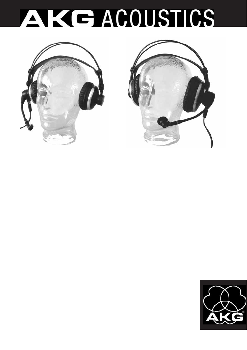
HSC 171
HSD 171
HSC 271
HSD 271
HSD 271 Single
Bedienungsanleitung . . . . . . . . . . . . S. 2
Bitte vor Inbetriebnahme des Gerätes lesen!
User Instructions . . . . . . . . . . . . . . p. 12
Please read the manual before using the equipment!
Mode d’emploi . . . . . . . . . . . . . . . . p. 22
Veuillez lire cette notice avant d’utiliser le système!
Istruzioni per l’uso . . . . . . . . . . . . . p. 32
Prima di utilizzare l’apparecchio, leggere il manuale
Modo de empleo . . . . . . . . . . . . . . . p. 42
¡Sirvase leer el manual antes de utilizar el equipo!
Instruções de uso . . . . . . . . . . . . . . p. 52
Por favor leia este manual antes de usar o equipamento!
1 Sicherheit und Umwelt
1.1 Sicherheit
1.2 Umwelt
2 Beschreibung
2.1 Einleitung
2.2 Lieferumfang
Tabelle 1: Headsets
und mitgeliefertes
Zubehör
• Überprüfen Sie bitte, ob das Gerät, an das Sie die Sprechgarnitur
anschließen möchten, den gültigen Sicherheitsbestimmungen entspricht und mit einer Sicherheitserdung versehen ist.
1. Wenn Sie das Gerät verschrotten, entfernen Sie die Batterien bzw.
Akkus, trennen Sie Gehäuse, Elektronik und Kabel und entsorgen Sie alle
Komponenten gemäß den dafür geltenden Entsorgungsvorschriften.
2. Die Verpackung ist recyclierbar. Entsorgen Sie die Verpackung in einem
dafür vorgesehenen Sammelsystem.
Vielen Dank, dass Sie sich für ein Produkt aus dem Hause AKG entschieden haben. Bitte lesen Sie die Bedienungsanleitung aufmerk-
sam durch, bevor Sie das Gerät benützen, und bewahren Sie die
Bedienungsanleitung sorgfältig auf, damit Sie jederzeit nachschlagen
können. Wir wünschen Ihnen viel Spaß und Erfolg!
HSC 171
1 x Headset
HSC 171
1 x Anschlusskabel mit
Phantomspeiseadapter
HSC-PA für Mikrofon
1 x Windschutz W 44 für
HSC 271
1 x Headset
HSC 271
Mikrofon
2 x Velours-Ohrpolster für Kopfhörer
HSD 171
1 x Headset
HSD 171
1 x Windschutz W HSD für Mikrofon
HSD 271
1 x Headset
HSD 271
1 x Anschlusskabel
HSD 271
Single
1 x Headset
HSD 271
Single
1 x Velours-
Ohrpolster
für
Kopfhörer
2.3 Allgemeine
Beschreibung
2
Kontrollieren Sie bitte, ob die Verpackung alle zu Ihrem Modell gehörenden Teile enthält. Falls etwas fehlt, wenden Sie sich bitte an Ihren
AKG-Händler.
Jedes der professionellen Headsets HSC 171, HSC 271, HSD 171,
HSD 271 und HSD 271 Single besteht aus einem Kopfhörer der AKG
Studio-Serie und einem auf einem flexiblen Mikrofonarm montierten
hochwertigen dynamischen oder Kondensatormikrofon. Der Frequenzgang dieser Mikrofone ist speziell für Sprachübertragung ausgelegt und
gewährleistet eine hervorragende Tonqualität. Die elastische Lagerung
des Mikrofons garantiert eine weitgehende Unterdrückung von Hantierungsgeräuschen.
Der Mikrofonarm ist um 270° schwenkbar für rechts- oder linksseitiges
Tragen und mit einer Mikrofon-Stummschaltfunktion ausgerüstet.
HSC 171/271, HSD 171/271/Single

2 Beschreibung
Das 3 m lange Anschlusskabel ist teilweise als Spiralkabel ausgeführt
und durch einen verriegelbaren 6-poligen Mini-XLR-Stecker mit dem
Headset verbunden. Diese Steckverbindung erlaubt einen raschen und
einfachen Austausch des Kabels.
Damit eignen sich die Headsets für alle Anwendungen im Rundkfunkund TV-Bereich, wo optimale Sprachwiedergabe erforderlich ist.
Mikrofon
Kopfhörer
Ein/Aus-
Automatik
für
Kopfhörer
HSC 171
Kondensator
ohraufliegend
–
HSC 271
Kondensator
ohr-
umschließend
✔
HSD 171
dynamisch
ohraufliegend
–
HSD 271,
HSD 271
Single
dynamisch
ohr-
umschließend
✔
3 Inbetriebnahme
2.4 Unterschiede
zwischen den
Modellen
Tabelle 2: Hauptmerkmale der einzelnen Modelle
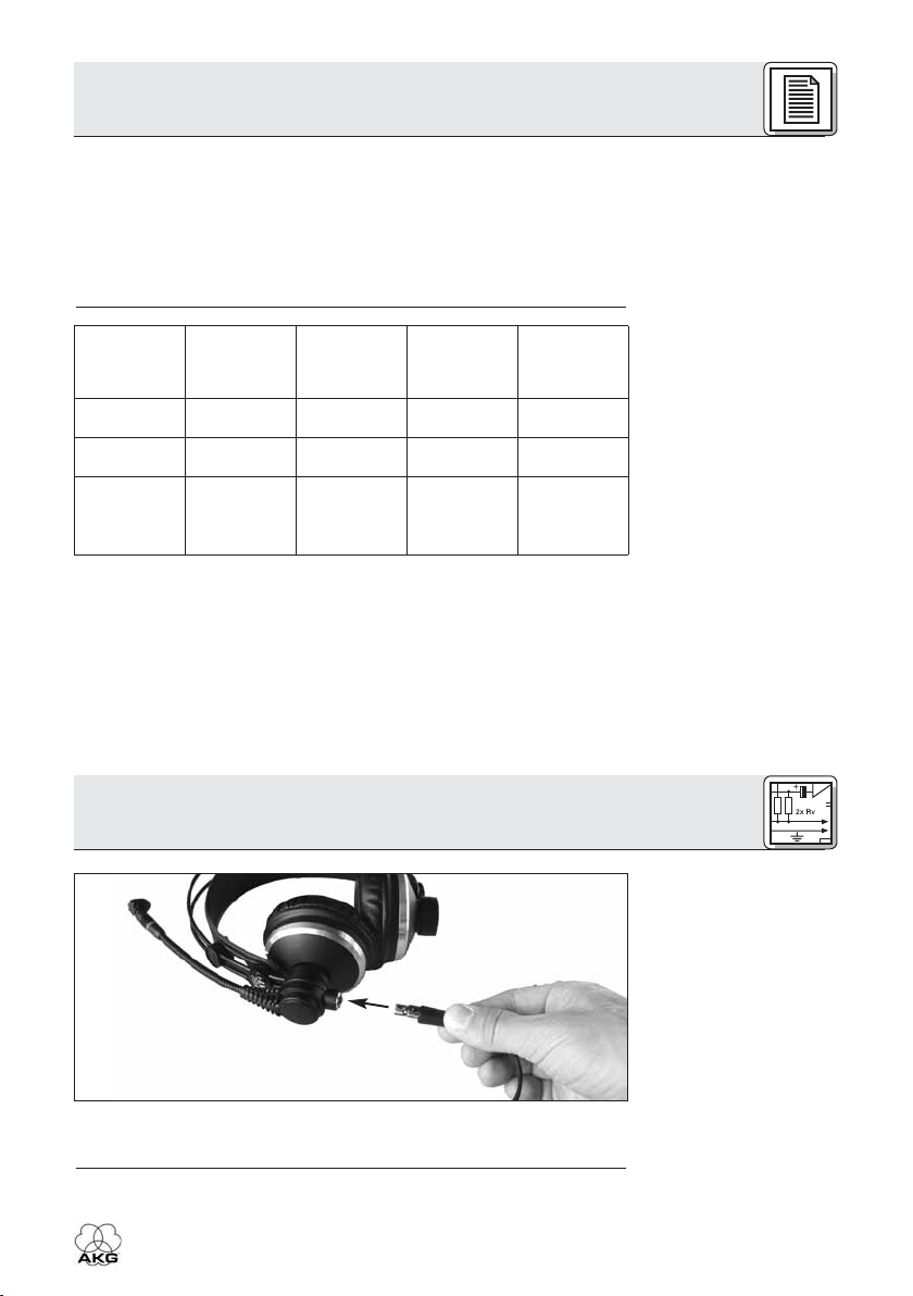
3.1 Anschlusskabel
anstecken
• Stecken Sie den 6-poligen Mini-XLR-Stecker (1) des Anschlusskabels in die Anschlussbuchse (2) des Headsets, bis sich der
Stecker mit einem hörbaren Klick automatisch verriegelt.
HSC 171/271, HSD 171/271/Single
Abb. 1: Anschlusskabel am Headset
anstecken.
Siehe Abb. 1.
3
3 Inbetriebnahme
3.2 Anschluss
3.2.1 HSC 171,
HSC 271
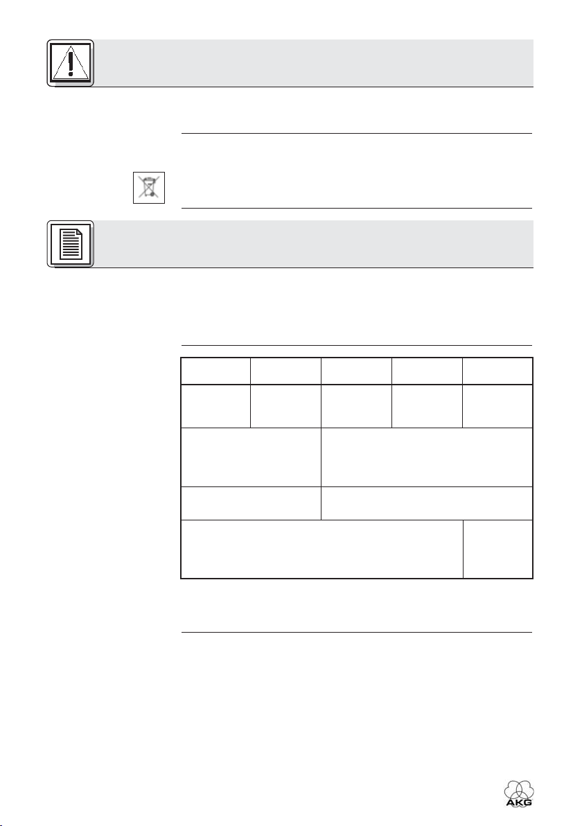
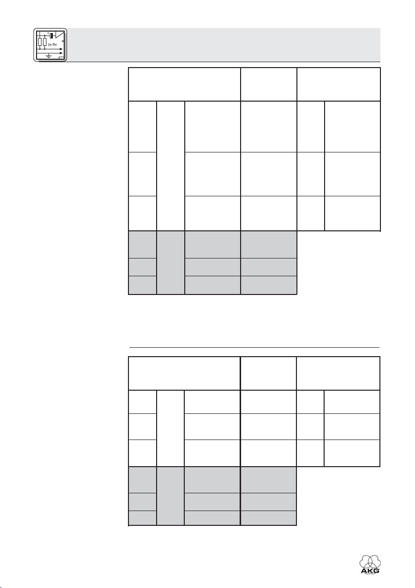
Tabelle 3:
Steckerbeschaltung
HSC 171, HSC 271
6-pol. Mini-XLR-Stecker
Abschirmung,
1
5
6
2
3
4
1. Schalten Sie das Mischpult aus.
2. Stecken Sie den Klinkenstecker an den gewünschten
Kopfhörerausgang an.
3. Stecken Sie den XLR-Stecker an den gewünschten
Mikrofoneingang an.
4. Schalten Sie das Mischpult ein.
5. Schalten Sie die Phantomspeisung ein.
Audio ",
versorgung "
Inphase,
Mikrofon
versorgung
Stumm-
schaltung
Abschirmung,
Audio links
Kopfhörer
Audio rechts
Masse,
Strom-
Audio
Strom-
Masse
6,3 mm-
Klinken-
stecker
Schaft
Ring
Spitze
XLR-Stecker am
Phantomspeise-
adapter
1
Abschirmung,
Masse
Audio
Inphase,
2
Phantom-
speisung
Audio ",
3
Phantom-
speisung "
3.1.2 HSD 171,
HSD 271,
HSD 271 Single
Tabelle 4:
Steckerbeschaltung
HSD 171, HSD 271,
HSD 271 Single
4
6-pol. Mini-XLR-Stecker
Abschirmung,
Audio Inphase
Mikrofon
Abschirmung,
Audio links
Kopfhörer
Audio rechts
Masse
Frei
Masse
1
5
6
2
3
4
6,3 mmKlinken-
stecker
Schaft
Ring
Spitze
HSC 171/271, HSD 171/271/Single
XLR-Stecker am
Phantomspeise-
adapter
Abschirmung,
1
2
3
Masse
Audio Inphase
Abschirmung,
Masse
3 Inbetriebnahme
1. Schalten Sie das Mischpult aus.
2. Stecken Sie den Klinkenstecker an den gewünschten Kopfhörerausgang an.
3. Stecken Sie den XLR-Stecker an den gewünschten Mikrofoneingang an.
4. Schalten Sie das Mischpult ein.
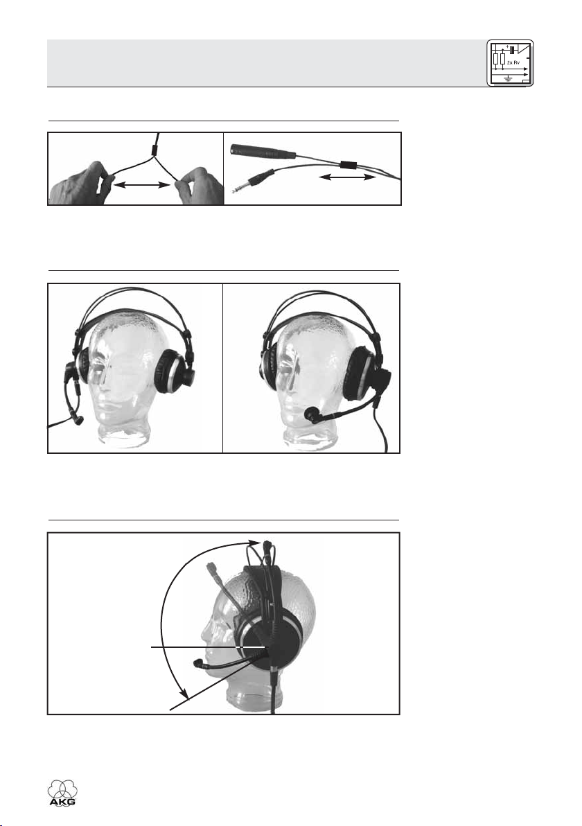
3.2.3 Anschlusskabel
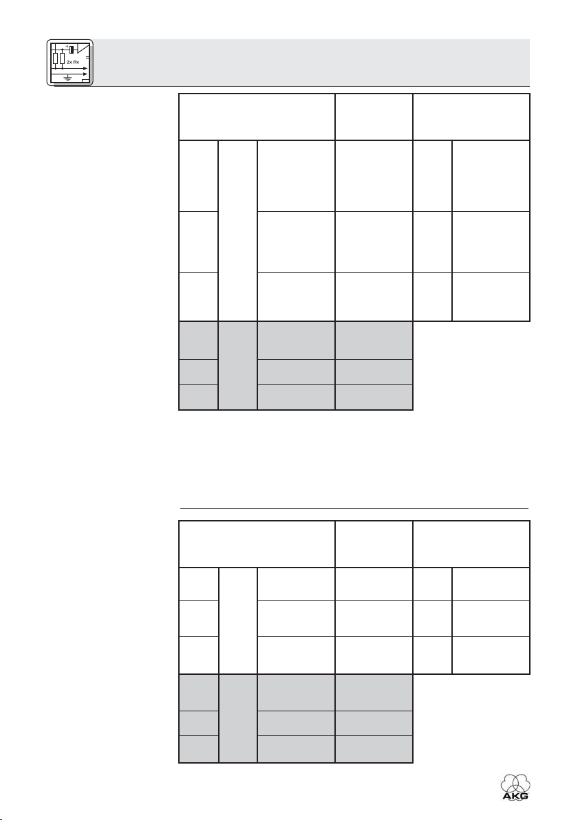
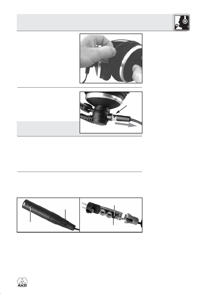
Abb. 2: Anschlusskabel auftrennen.
Das Mikrofonkabel ist mit dem Kopfhörerkabel verschweißt. Falls
Kopfhörerausgang und Mikrofoneingang zu weit voneinander entfernt
sind, können Sie das Mikrofonkabel einfach vom Kopfhörerkabel wegziehen. Mit Hilfe der Tülle können Sie die getrennten Kabel wieder
zusammenhalten.
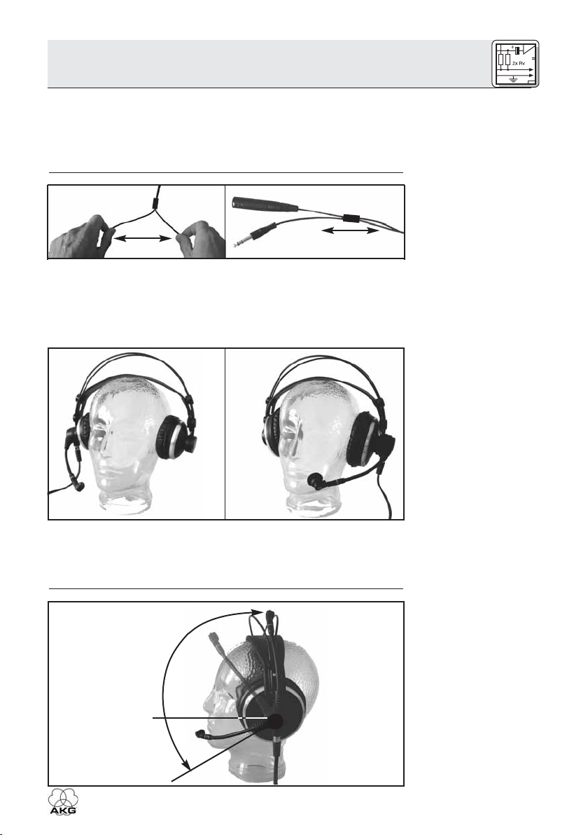
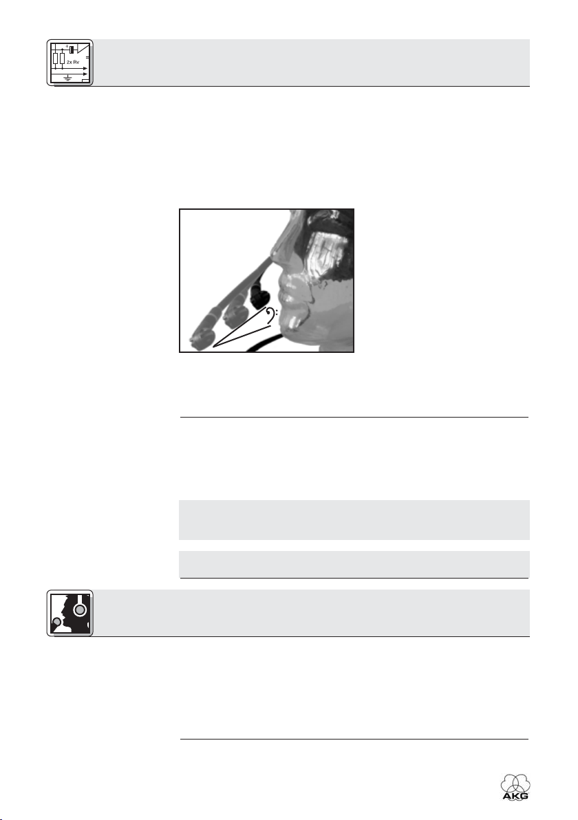
Der Mikrofonarm ist über einen Bereich von 270° schwenkbar. Sie können das Headset daher so aufsetzen, dass das Mikrofon je nach
Erfordernis oder Platzverhältnissen entweder links oder rechts vor dem
Mundwinkel sitzt.
MUTE
Siehe Abb. 2.
3.3 Headset
aufsetzen
Abb. 3: Mögliche
Positionen des
Headsets am Kopf.
Siehe Abb. 3.
3.4 Mikrofon
ein/ausschalten und
testen
ON
HSC 171/271, HSD 171/271/Single
Abb. 4: Der
Mikrofonarm schaltet
bei allen Modellen das
Mikrofon ein (ON) und
stumm (MUTE).
5
3 Inbetriebnahme
Der Mikrofonarm aller Modelle ist mit einer Stummschaltfunktion ausgestattet.
Siehe Abb. 4
auf Seite 5.
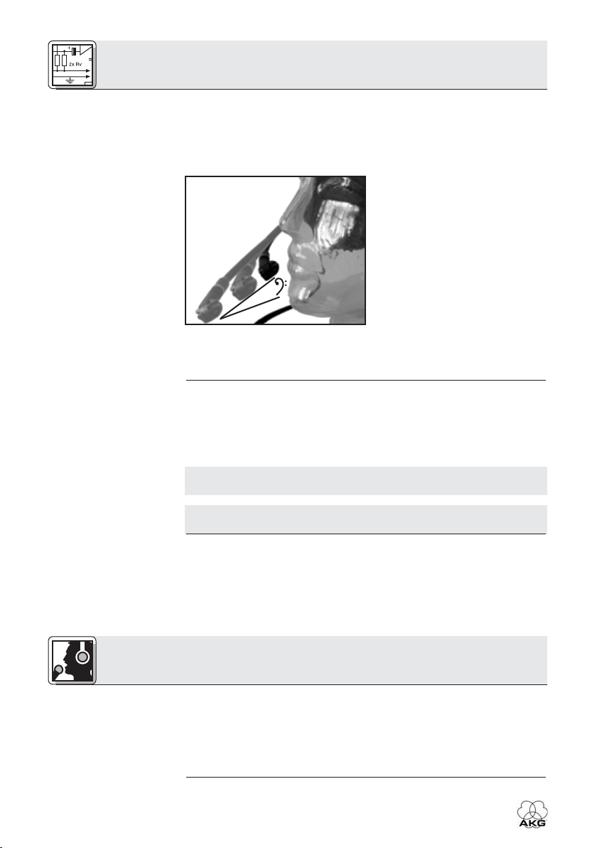
Abb. 5: Der Klang des
Mikrofons hängt vom
Besprechungs-
abstand ab.
3.5 Kopfhörer
ein/ausschalten
(HSC 271, HSD 271,
HSD 271 Single)
Hinweis:
1. Um das Mikrofon einzuschalten, schwenken Sie den Mikrofonarm
soweit nach unten, bis das Mikrofon vor dem Mundwinkel liegt. Das
Mikrofon schaltet sich ein, sobald der Mikrofonarm etwa waagrecht
steht.
2. Sprechen Sie in das Mikrofon.
Siehe Abb. 5:
Der flexible Mikrofonarm erlaubt
Ihnen, den Abstand des Mikrofons
vom Mund und damit die Klangcharakteristik zu variieren: je größer der Abstand, desto geringer
der Tiefenanteil (und der Pegel)
des Audiosignals.
3. Um das Mikrofon stummzuschalten, schwenken Sie den
Mikrofonarm bis in die gerastete Mittenposition nach oben. Das
Mikrofon schaltet sich aus, sobald der Mikrofonarm höher als waagrecht steht.
Der Kopfhörer der Modelle HSC 271, HSD 271 und HSD 271 Single
schaltet sich automatisch ein, sobald Sie das Headset aufsetzen. Wenn
Sie das Headset abnehmen, schaltet sich der Kopfhörer automatisch
aus. Dies verhindert ein Übersprechen des Kopfhörersignals in das
Mikrofon, wenn Sie das Headset ablegen.
Der Ein/Ausschalter wird durch das Bügelband betätigt. Wenn Sie das
Headset am Bügelband aufhängen, kann sich der Kopfhörer einschalten.
Hinweis:
4 Anwendungshinweise
4.1 Windschutz
W 44 (HSC 171/271),
W HSD (HSD 171/
271/271 Single)
6
Der Kopfhörer der Modelle HSC 171 und HSD 171 besitzt keine
Ein/Ausschaltautomatik.
Wenn Sie das Headset im Freien verwenden oder das Mikrofon extrem
nahe am Mund platzieren müssen, empfehlen wir, den mitgelieferten
Schaumstoff-Windschutz am Mikrofon zu befestigen.
1. Stecken Sie den Windschutz auf die Mikrofonkapsel auf.
2. Ziehen Sie den Windschutz auch über das äußere Ende der
Mikrofonkapsel.
HSC 171/271, HSD 171/271/Single
4 Anwendungshinweise
Siehe Abb. 6:
1. Ziehen Sie den/die Ohrpolster
vom/von den Hörsystem/en
ab.
2. Zum Befestigen des/der neuen
Ohrpolster/s ziehen Sie den
elastischen Saum rundherum
über die Grundplatte des Hörsystems.
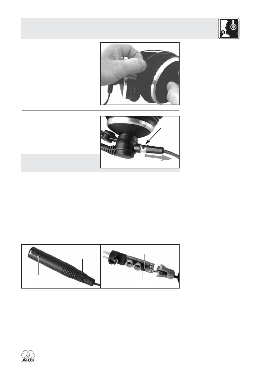
Siehe Abb. 7:
1. Drücken Sie den Verriegelungsknopf am Stecker in den
Stecker hinein.
2. Ziehen Sie das Anschlusskabel
vom Headset ab.
Hinweis: Wenn Sie das Kabel wie-
der anstecken, verriegelt sich
der Stecker automatisch.
• Um zu verhindern, dass das Mikrofon unerwünschte Signale aufnimmt oder Rückkopplungen verursacht (die Modelle HSC 171 und
HSD 171 sind mit keiner Abschaltautomatik für den Kopfhörer ausgestattet), schwenken Sie den Mikrofonarm immer in die vertikale
Mittenposition, bevor Sie das Headset abnehmen.
Damit ist das Mikrofonsignal stummgeschaltet, selbst wenn der
Mikrofonkanal offen bleibt.
Der Phantomspeiseadapter HSC-PA ist mit einer Bassabschwächung
zur Unterdrückung tieffrequenter Störgeräusche und zur Reduktion des
Naheffekts ausgestattet. Im Lieferzustand ist die Bassabschwächung
deaktiviert. Sie können die Bassabschwächung wie folgt aktivieren:
1
2
4.2 Ohrpolster
austauschen
Abb. 6: Ohrpolster
austauschen.
4.3 Anschlusskabel
abziehen
Abb. 7: Anschlusskabel abziehen.
4.4 Störgeräusche,
Rückkopplung
4.5 Bassabschwächung
(HSC 171, HSC 272)
2
1
1. Ziehen Sie den Phantomspeiseadapter vom Mischpulteingang ab.
2. Lösen Sie die Befestigungsschraube (1) am Phantomspeiseadapter.
3. Schrauben Sie die Kabelmuffe (2) ab.
4. Ziehen Sie den Print VORSICHTIG aus dem Gehäuse heraus.
5. Ziehen Sie die Drahtbrücke (3) von den Kontaktstiften (4) ab. Die
Bassabschwächung ist nun aktiviert.
Um die Drahtbrücke (3) nicht zu verlieren, stecken Sie sie um 90°
gedreht auf zwei der Kontaktstifte (4).
HSC 171/271, HSD 171/271/Single
4
3
Abb. 8: Phantomspeiseadapter öffnen.
Siehe Abb. 8.
7
4 Anwendungshinweise
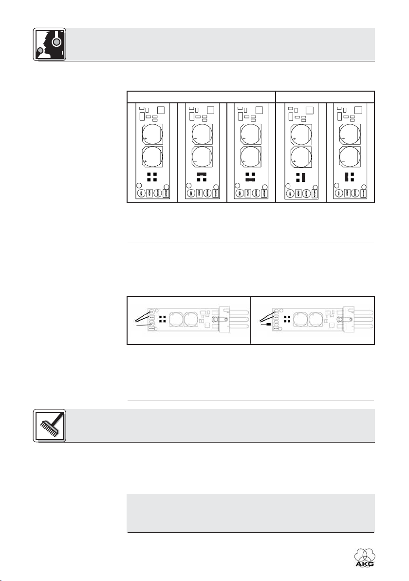
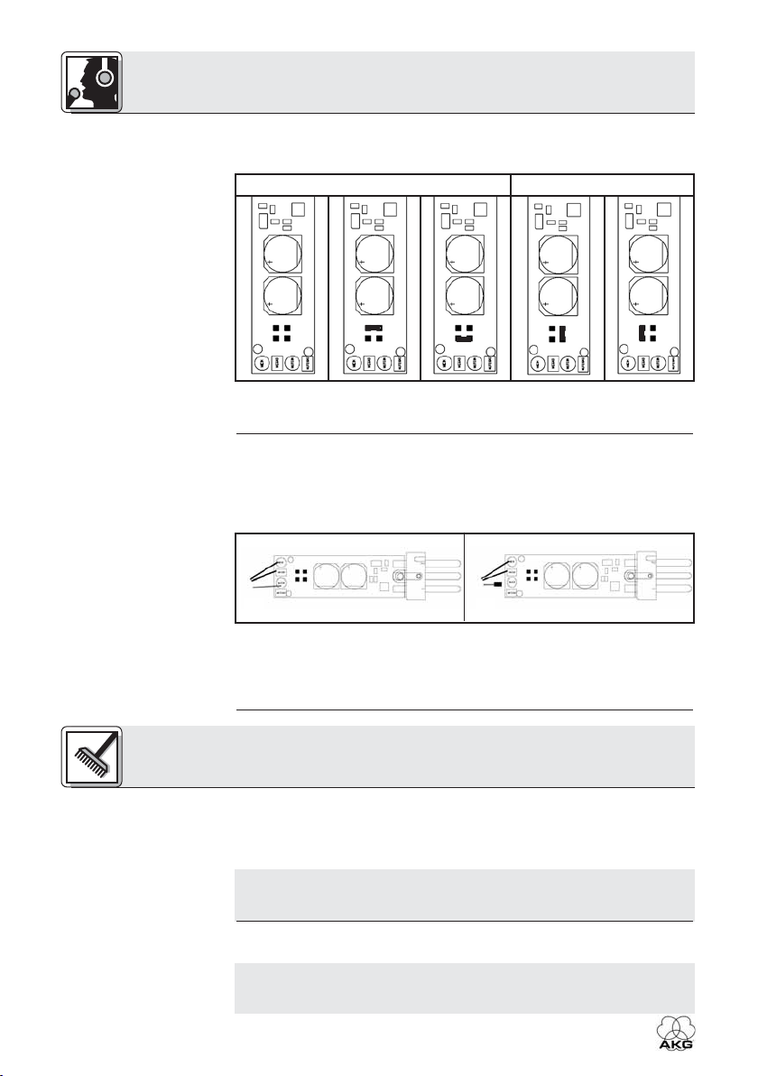
Siehe Tabelle 5.
Tabelle 5: Positionieren
der Drahtbrücke zum
Ein- und Ausschalten
der Bassabschwächung.
4.6 Mikrofon-
Stummschaltauto-
matik deaktivieren
Siehe Abb. 8.
Abb. 9: Mikrofon-
Stummschaltautomatik
EIN (a) und AUS (b).
• Zum Deaktivieren der Bassabschwächung stecken Sie die Drahtbrücke (3) auf zwei der Kontaktstifte (4).
Bassabschwächung EIN Bassabschwächung AUS
6. Schieben Sie den Print in das Gehäuse ein, ziehen Sie die Befestigungsschraube (1) an und schrauben Sie die Kabelmuffe (2) auf die
blaue Zugentlastung (5) auf.
1. Ziehen Sie den Phantomspeiseadapter vom Mischpulteingang ab.
2. Lösen Sie die Befestigungsschraube (1) am Phantomspeiseadapter.
3. Schrauben Sie die Kabelmuffe (2) ab.
4. Ziehen Sie den Print VORSICHTIG aus dem Gehäuse heraus.
a b
Siehe Abb. 9.
Siehe Abb. 8.
5.1 Kopfhörer,
Anschlusskabel
8
5. Löten Sie die grüne Ader vom Print ab und isolieren Sie das blanke
Ende mit Isolierband.
6. Schieben Sie den Print in das Gehäuse ein, ziehen Sie die
Befestigungsschraube (1) an und schrauben Sie die Kabelmuffe (2)
auf die blaue Zugentlastung auf.
5 Reinigung
Mikrofon,
Wichtig!
1. Ziehen Sie das Kopfhörer- und das Mikrofonkabel vom Mischpult
ab.
2. Reinigen Sie die Oberflächen des Gerätes mit einem mit Wasser
befeuchteten, aber nicht nassen Tuch.
• Verwenden Sie keinesfalls scharfe oder scheuernde Reinigungsmittel sowie keine, die Alkohol oder Lösungsmittel enthalten, da diese den Lack sowie die Kunststoffteile beschädigen könnten.
HSC 171/271, HSD 171/271/Single
5 Reinigung
1. Nehmen Sie den Windschutz vom Mikrofon ab.
• Ziehen Sie den Windschutz W HSD mit großer Vorsicht vom
Mikrofon des HSD 171/271/Single ab, um den fix am Mikrofon
befestigten Windschutz nicht zu beschädigen!
2. Reinigen Sie den Windschutz mit Seifenwasser.
3. Lassen Sie den Windschutz über Nacht trocknen.
4. Stecken Sie den Windschutz auf die Mikrofonkapsel auf.
5. Ziehen Sie den Windschutz auch über das äußere Ende der
Mikrofonkapsel.
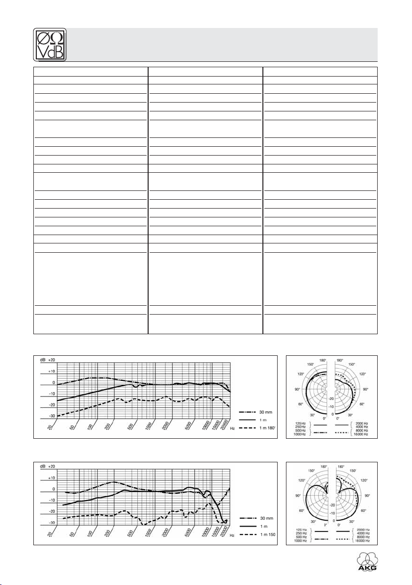
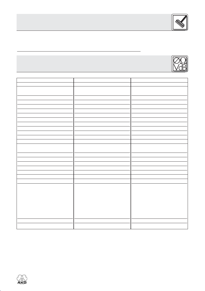
6 Technische Daten
Mikrofon
Arbeitsweise:
Richtcharakteristik:
Übertragungsbereich:
Empfindlichkeit:
Grenzschalldruckpegel (k=1%):
Äquivalentschalldruckpegel:
Signal/Rauschabstand
(A-bew.):
Elektrische Impedanz:
Empfohlene Lastimpedanz:
Speisespannung:
Stromaufnahme:
Kopfhörer
Bauweise:
Kennschalldruckpegel:
Übertragungsbereich:
Nennbelastbarkeit:
Nennimpedanz:
Klirrfaktor:
System
Anschlussstecker:
Kabel:
Oberfläche:
Gewicht:
HSC 171
Kondensatormikrofon mit
Permanentladung
Niere
20 - 20000 Hz
25 mV/Pa
126 dB
22 dB(A)
72 dB
≤200 Ohm
≥2000 Ohm
9 - 52 V Phantomspeisung
≤2 mA
geschlossener, ohraufliegender,
dynamischer Kopfhörer
94 dB SPL/mW
18 - 26.000 Hz
200 mW
55 Ohm
<0,4 %
6-poliger Mini-XLR-Stecker
2 x 3-polig, auftrennbar, 3 m
lang, teilweise spiralisiert, mit
6-poliger Mini-XLR-Kupplung,
6,3 mm-Stereo-Klinkenstecker
(Kopfhörer) und 3-poligem
XLR-Stecker mit integriertem
Phantomspeiseadapter
HSC-PA (Mikrofon)
mattschwarz
250 g
HSC 271
Kondensatormikrofon mit
Permanentladung
Niere
20 - 20000 Hz
25 mV/Pa
126 dB
22 dB(A)
72 dB
≤200 Ohm
≥2000 Ohm
9 - 52 V Phantomspeisung
≤2 mA
geschlossener, ohrumschließender, dynamischer Kopfhörer
94 dB SPL/mW
16-28.000 Hz
200 mW
55 Ohm
<0,3 %
6-poliger Mini-XLR-Stecker
2 x 3-polig, auftrennbar, 3 m
lang, teilweise spiralisiert, mit
6-poliger Mini-XLR-Kupplung,
6,3 mm-Stereo-Klinkenstecker
(Kopfhörer) und 3-poligem
XLR-Stecker mit integriertem
Phantomspeiseadapter
HSC-PA (Mikrofon)
mattschwarz
300 g
5.2 Windschutz
W 44, W HSD
Wichtig!
HSC 171/271, HSD 171/271/Single
9
6 Technische Daten
Mikrofon
Arbeitsweise:
Richtcharakteristik:
Übertragungsbereich:
Empfindlichkeit:
Grenzschalldruckpegel
(k=1%/3%):
Äquivalentschalldruckpegel:
Elektrische Impedanz:
Empfohlene Lastimpedanz:
Kopfhörer
Bauweise:
Kennschalldruckpegel:
Übertragungsbereich:
Nennbelastbarkeit:
Nennimpedanz:
Klirrfaktor:
System
Anschlussstecker:
Kabel:
Oberfläche:
Gewicht:
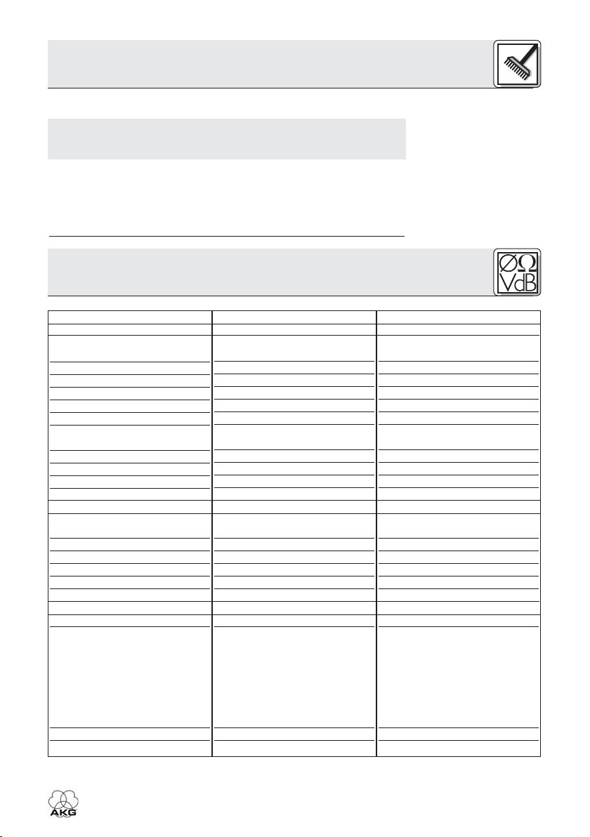
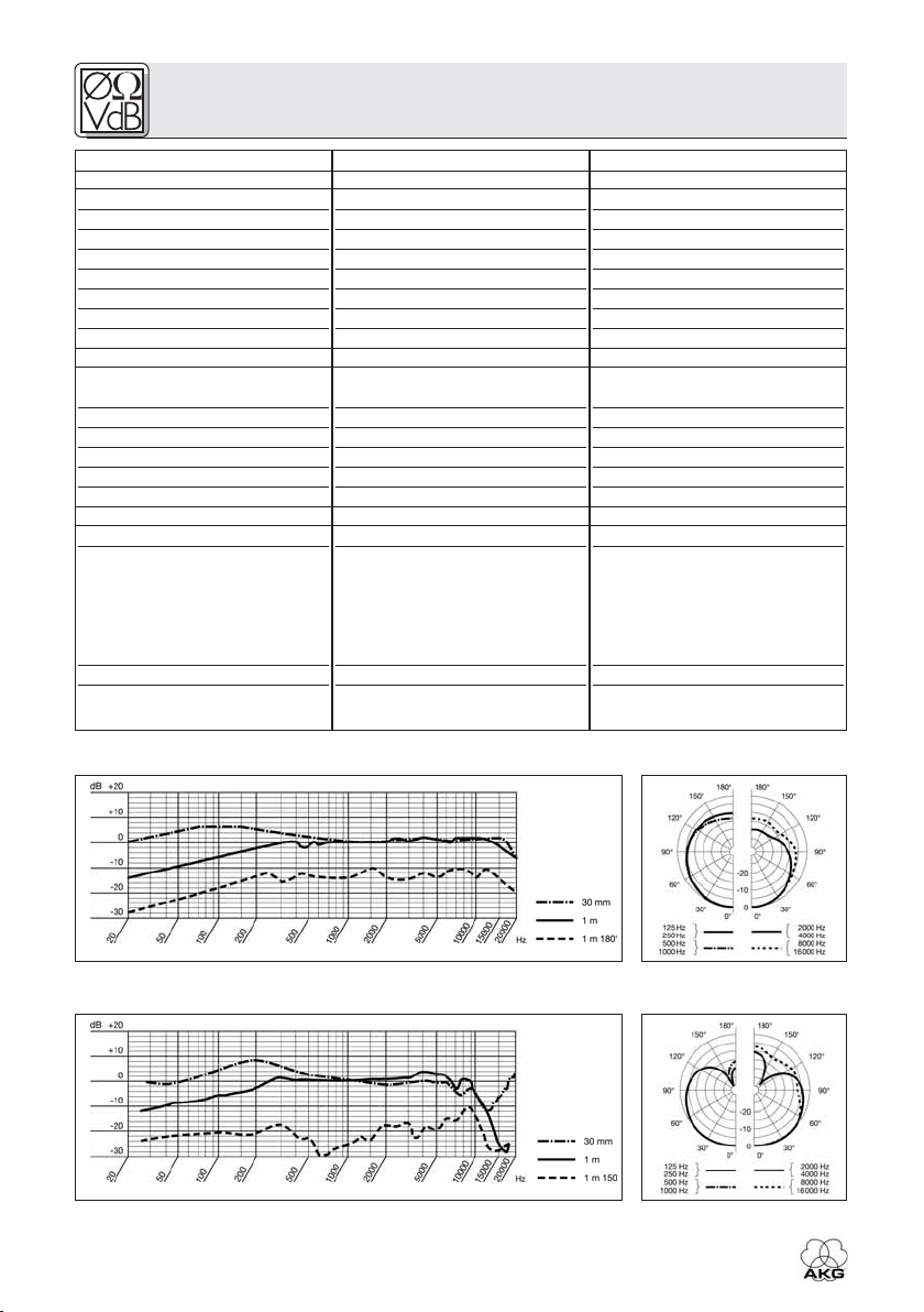
Frequenzgang und Polardiagramm HSC 171, HSC 271
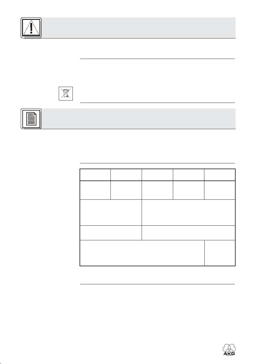
HSD 171
dynamisch
Hyperniere
60 - 17.000 Hz
1 mV/Pa (-60 dBV)
124/128 dB SPL
15 dB(A)
≤600 Ohm
≥2.000 Ohm
geschlossener, ohraufliegender,
dynamischer Kopfhörer
94 dB SPL/mW
18 - 26.000 Hz
200 mW
55 Ohm
<0,4 %
6-poliger Mini-XLR-Stecker
2 x 3-polig, auftrennbar, 3 m
lang, teilweise spiralisiert, mit
6-poliger Mini-XLR-Kupplung,
6,3 mm-Stereo-Klinkenstecker
(Kopfhörer) und 3-poligem
XLR-Stecker (Mikrofon)
mattschwarz
255 g
HSD 271, HSD 271 Single
dynamisch
Hyperniere
60 - 17.000 Hz
1 mV/Pa (-60 dBV)
124/128 dB SPL
15 dB(A)
≤600 Ohm
≥2.000 Ohm
geschlossener, ohrumschließender, dynamischer Kopfhörer
94 dB SPL/mW
16 - 28.000 Hz
200 mW
55 Ohm
<0,3 %
6-poliger Mini-XLR-Stecker
2 x 3-polig, auftrennbar, 3 m
lang, teilweise spiralisiert, mit
6-poliger Mini-XLR-Kupplung,
6,3 mm-Stereo-Klinkenstecker
(Kopfhörer) und 3-poligem
XLR-Stecker (Mikrofon)
mattschwarz
HSD 271: 305 g
HSD 271 Single: 265 g
Frequenzgang und Polardiagramm HSD 171, HSD 271, HSD 271 Single
10
HSC 171/271, HSD 171/271/Single

6 Technische Daten
Dieses Produkt entspricht den in der Konformitätserklärung
angegebenen Normen. Sie können die Konformitätserklärung auf
http://www.akg.com oder per E-Mail an sales@akg.com anfordern.
Ersatzteile können Sie bei AKG Acoustics GmbH, Serviceabteilung,
Lemböckgasse 21-25, A-1230 Wien bestellen. Bitte geben Sie bei der
Bestellung für jeden Ersatzteil die entsprechende Artikelnummer an.
Artikel
ECV 171
ECV 271
ECL 171
ECL 271
W HSD
W 44
MK HSC
MK HSD
Bezeichnung
Ohrpolster 171, velour
Ohrpolster 271, velour
Ohrpolster 171, glatt
Ohrpolster 271, glatt
Windschutz
für HSD 171/271/Single
Windschutz
für HSC 171/271
Ersatzkabel mit
Phantomspeiseadapter für
HSC 171/271
Ersatzkabel mit
3-pol. XLR-Stecker für
HSD 171/271/Single
Artikelnummer
2955Z2501
2955Z2601
2908Z1301
2058Z1001
2955Z2401
2344Z0101
2397Z0015
2542K0001
6.1 Normen
6.2 Ersatzteilliste
HSC 171/271, HSD 171/271/Single
11
1 Safety and Environment
1.1 Safety
1.2 Environment
2 Description
2.1 Introduction
2.2 Unpacking
Table 1: Headsets and
standard accessories.
• Please make sure that the piece of equipment your microphone will
be connected to fulfills the safety regulations in force in your country and is fitted with a ground lead.
1. When scrapping the equipment, separate the case, circuit boards,
and cables, and dispose of all components in accordance with local
waste disposal rules.
2. The packaging of the equipment is recyclabe. To dispose of the
packaging, make sure to use a collection/recycling system provided
for that purpose and observe local legislation relating to waste disposal and recycling.
Thank you for purchasing an AKG product. This Manual contains
important instructions for setting up and operating your equipment.
Please take a few minutes to read the instructions below carefully
before operating the equipment. Please keep the Manual for future
reference. Have fun and impress your audience!
HSC 171
1 x HSC 171
headset
1 x connecting cable
with HSC-PA phantom
power adapter
for microphone
1 x W 44 windscreen for
HSC 271
1 x HSC 271
headset
microphone
2 x velour ear pads for headphones
HSD 171
1 x HSD 171
headset
1 x W HSD windscreen for microphone
HSD 271
1 x HSD 271
headset
1 x connecting cable
HSD 271
Single
1 x HSD 271
Single
headset
1 x velour
ear pad
for head-
phones
12
2.3 General
Description
Check that the packaging contains all of the items listed for your model.
Should any item be missing, please contact your AKG dealer.
Each of the professional headsets HSC 171, HSC 271, HSD 171,
HSD 271, and HSD 271 Single combines a pair of AKG Studio line
headphones or a single earphone with a high quality dynamic or condenser microphone mounted on a flexible microphone arm. The frequency response of each microphone has been designed specifically
for speech reproduction and ensures excellent audio quality. The microphones are shock mounted to minimize handling noise.
HSC 171/271, HSD 171/271/Single
2 Description
The microphone arm features a microphone muting function and
swivels through a 270-degree arc so you can wear the headset with the
microphone on your left or right.
The 10-foot (3-m) connecting cable has a coiled section and interfaces
with the headset through a 6-pin mini XLR connector. This connection
allows you to replace the cable quickly and easily.
All models are suited for any radio or TV application requiring optimum
speech reproduction.
Microphone
Headphones
Headphone
ON/MUTE
function
HSC 171
condenser
supraaural
–
HSC 271
condenser
circumaural
✔
HSD 171
dynamic
supraaural
–
HSD 271,
HSD 271
Single
dynamic
circumaural
✔
2.4 Differences
between Models
Table 2: Distinguishing
features of each
model.
3 Setting Up
3.1 Plugging in the
Connecting Cable
• Insert the 6-pin mini XLR connector (1) on the connecting cable into
the matching socket (2) on the headset and push home to the point
that the connector will lock with an audible click.
HSC 171/271, HSD 171/271/Single
Fig. 1: Plugging the
connecting cable into
the headset.
Refer to fig. 1.
13
3 Setting Up
3.2 Connecting to
Audio Equipment
3.2.1 HSC 171,
HSC 271
Table 3: HSC 171 and
HSC 271 connector
pinouts.
6-pin mini XLR connector
shield,
1
5
6
2
3
4
1. Switch power to the mixer OFF.
2. Plug the jack plug into the desired headphone output.
3. Plug the XLR connector into the desired microphone input.
4. Switch power to the mixer ON.
5. Switch phantom power ON.
ground, audio
return, neg.
supply volt-
age
audio
inphase, pos.
supply volt-
Microphone
Headphones
age
mute signal
shield,
ground
audio left
audio right
1/4" jack
plug
shaft
ring
tip
XLR connector on
phantom power
adapter
shield,
1
2
3
ground
inphase, pos.
phantom volt-
audio return,
neg. phantom
voltage
audio
age
3.2.2 HSD 171,
HSD 272 Single
Table 4: HSD 171,
HSD 271, and
HSD 271 Single
connector pinouts.
14
HSD 272,
6-pin mini XLR connector
1
5
6
2
3
4
1. Switch power to the mixer OFF.
2. Plug the jack plug into the desired headphone output.
shield, ground
audio inphase
Microphone
unused
shield, ground
audio left
audio right
Headphones
1/4" jack
plug
shaft
ring
tip
HSC 171/271, HSD 171/271/Single
XLR connector on
phantom power
adapter
1
2
3
shield, ground
audio inphase
shield, ground
3. Plug the XLR connector into the desired microphone input.
4. Switch power to the mixer ON.
3 Setting Up
3.2.3 Connecting
Cable
Fig. 2: Separating
microphone and headphone cables.
The microphone cable is welded to the headphone cable. If the headphone output is too far away from the microphone input, you can simply pull the microphone cable away from the headphone cable. The
sliding bush lets you bundle the separated cables together again.
The microphone arm swivels through an arc of 270 degrees, allowing
you to put the headset on with the microphone sitting in front of either
the left or right corner of your mouth as required by the job at hand or
dictated by available space.
MUTE
Refer to fig. 2.
3.3 Putting the
Headset On
Fig. 3: Two ways of
wearing the headset.
Refer to fig. 3.
3.4 Switching the
Microphone ON/OFF
and Testing It
ON
The microphone arm of each model features an automatic ON/MUTE
switch.
HSC 171/271, HSD 171/271/Single
Fig. 4: The microphone arm of each
model switches the
microphone ON or
MUTEs it.
Refer to fig. 4.
15
3 Setting Up
Fig. 5: The micro-
phone sound depends
on the microphone's
distance from the
mouth.
1. To switch the microphone ON, move the microphone arm down far
enough to place the microphone in front of the corner of your mouth.
The microphone will switch ON as soon as the microphone arm
reaches a position lower than horizontal.
2. Talk into the microphone.
Refer to fig. 5:
The flexible microphone arm
allows you to adjust the microphone sound by varying the working distance. As you move the
microphone away from your
mouth, the bass content (and
overall level) of the audio signal
will decrease.
3. To mute the microphone, move the microphone arm up into its
detented center position. The microphone will be muted as the
microphone arm reaches a position higher than horizontal.
3.5 Switching
Headphones
ON/OFF
(HSC 271, HSD 271,
HSD 271 Single)
Note:
Note:
4 Operating Notes
4.1 Windscreens
W 44
(HSC 171/271),
W HSD
(HSD 171/271/271
Single)
The headphones on models HSC 271, HSD 271, and HSD 271 Single
will switch ON automatically as you put the headset on. When you take
the headset off, the headphones will switch OFF automatically. This
prevents the headphone signal from leaking into the microphone on
taking the headset off.
The on/off switch is actuated by the headband. If you hang the headset up by the headband, the headphones may switch ON.
The headphones on models HSC 171 and HSD 171 feature no automatic on/off switch.
If you use the headset in the open or need to place the microphone
extremely close to your mouth, we recommend using the supplied foam
windscreen.
1. Slide the windscreen onto the microphone capsule.
2. Pull the windscreen over the outer edge of the microphone capsule.
16
HSC 171/271, HSD 171/271/Single
4 Operating Notes
Refer to fig. 6:
1. Pull the ear pad(s) off the earphone(s).
2. To attach the new ear pad(s),
pull the elastic hem of each ear
pad over the rim of the earphone base plate all around.
Refer to fig. 7:
1. Grasp the connector, depressing the locating button.
2. Pull the connecting cable off
the headset.
Note: When you connect the
cable again, the connector will
lock automatically.
• To prevent the microphone from picking up unwanted signals or
causing feedback (models HSC 171 and HSD 171 provide no headphone muting function), be sure to move the microphone arm into
its vertical center position every time before taking the headset off.
This keeps the microphone signal muted even if the microphone
channel remains open.
The HSC-PA phantom power adapter features a bass cut filter to suppress low-frequency noise and reduce proximity effect. The headsets
are delivered with the bass cut filter deactivated. To activate the bass
cut filter:
1
2
4.2 Replacing
Ear Pads
Fig. 6: Replacing ear
pads.
4.3 Unplugging the
Connecting Cable
Fig. 7: Unplugging the
connecting cable.
4.4 Unwanted
Noise, Feedback
4.5 Bass Cut Filter
(HSC 171, HSC 271)
2
1
1. Disconnect the phantom power adapter from the mixer input.
2. Remove the fixing screw (1) from the phantom power adapter.
2. Unscrew the cable bushing (2).
4. Pull the pcb out of the shell WITH EXTRA CARE.
5. Remove the jumper (3) from the contact pins (4) to activate the bass
cut filter.
In order not to lose the jumper (3), place it on any two contact pins
(4) in a position at right angles to the ON position.
HSC 171/271, HSD 171/271/Single
4
3
Fig. 8: Opening the
phantom power
adapter.
Refer to fig. 8.
17
4 Operating Notes
Refer to Table 5.
Table 5: Jumper posi-
tions for activating and
deactivating the bass
cut filter.
4.6 Deactivating the
Microphone Muting
Function
Refer to fig. 8.
Fig. 9: Microphone
muting function ON (a)
and OFF (b).
Refer to fig. 9.
Refer to fig. 8.
• To deactivate the bass cut filter, place the jumper (3) on any two contact pins (4) as per Table 5 below.
Bass cut filter ON Bass cut filter OFF
6. Push the pcb into the shell, replace and tighten the fixing screw (1),
and screw the cable bushing (2) onto the blue strain relief (5).
1. Disconnect the phantom power adapter from the mixer input.
2. Remove the fixing screw (1) from the phantom power adapter.
2. Unscrew the cable bushing (2).
4. Pull the pcb out of the shell WITH EXTRA CARE.
a b
5. Unsolder the green wire from the pcb and insulate the stripped end
with insulating tape.
6. Push the pcb into the shell, replace and tighten the fixing screw (1),
and screw the cable bushing (2) onto the blue strain relief (5).
5 Cleaning
5.1 Headphones,
Microphone,
Connecting Cable
Important!
5.2 W 44, W HSD
Windscreens
Important!
18
1. Disconnect the headphone and microphone cables from the mixer.
2. Use a cloth moistened (not wet!) with water to clean the surfaces of
the equipment.
• Never use caustic or scouring cleaners or cleaning agents containing alcohol or solvents since these may damage the enamel or plastic parts.
1. Remove the windscreen from the microphone.
• To avoid damaging the windscreen fixed on the microphone, be
extremely careful in removing the W HSD from the HSD 171/271/271
Single microphone!
HSC 171/271, HSD 171/271/Single
5 Cleaning
2. Wash the windscreen in soap suds.
3. Allow the windscreen to dry overnight.
4. Slide the windscreen onto the microphone capsule.
5. Pull the windscreen over the outer edge of the microphone capsule.
6 Specifications
Microphone
Type:
Polar pattern:
Frequency range:
Sensitivity:
Max. SPL for 1% THD:
Equivalent noise level:
Signal/noise ratio (A-weighted):
Electrical impedance:
Recommended load impedance:
Power requirement:
Current consumption:
Headphones
Type:
Sensitivity:
Frequency range:
Power rating:
Rated impedance:
THD:
System
Connector:
Cable:
Finish:
Weight:
HSC 171
prepolarized condenser microphone
cardioid
20 Hz to 20 kHz
25 mV/Pa
126 dB
22 dB(A)
72 dB
≤200 ohms
≥2000 ohms
9 to 52 V phantom power
≤2 mA
closed-back, supraaural
dynamic headphones
94 dB SPL/mW
18 Hz to 26 kHz
200 mW
55 ohms
<0.4%
6-pin mini XLR connector
2 x 3-conductor; separable;
10 ft. (3 m) long; coiled section;
with 6-pin female mini XLR
connector, 1/4" TRS jack plug
(headphones), and 3-pin XLR
connector w/integrated
HSC-PA phantom power
adapter (microphone)
matte black
250 g (8.8 oz.)
HSC 271
prepolarized condenser microphone
cardioid
20 Hz to 20 kHz
25 mV/Pa
126 dB
22 dB(A)
72 dB
≤200 ohms
≥2000 ohms
9 to 52 V phantom power
≤2 mA
closed-back, circumaural
dynamic headphones
94 dB SPL/mW
16 Hz to 28 kHz
200 mW
55 ohms
<0.3%
6-pin mini XLR connector
2 x 3-conductor; separable;
10 ft. (3 m) long; coiled section;
with 6-pin female mini XLR
connector, 1/4" TRS jack plug
(headphones), and 3-pin XLR
connector w/integrated
HSC-PA phantom power
adapter (microphone)
matte black
300 g (10.6 oz.)
HSC 171/271, HSD 171/271/Single
19
6 Specifications
Microphone
Type:
Polar pattern:
Frequency range:
Sensitivity:
Max. SPL for 1%/3% THD:
Equivalent noise level:
Electrical impedance:
Recommended load impedance:
Headphones
Type:
Sensitivity:
Frequency range:
Power rating:
Rated impedance:
THD:
System
Connector:
Cable:
Finish:
Weight:
HSC 171, HSC 271 Frequency Response and Polar Diagram
HSD 171
dynamic
hypercardioid
60 Hz to 17 kHz
1 mV/Pa (-60 dBV)
124/128 dB
15 dB(A)
≤600 ohms
≥2000 ohms
closed-back, supraaural
dynamic headphones
94 dB SPL/mW
18 Hz to 26 kHz
200 mW
55 ohms
<0.4%
6-pin mini XLR connector
2 x 3-conductor; separable;
10 ft. (3 m) long; coiled section;
with 6-pin female mini XLR
connector, 1/4" TRS jack plug
(headphones), and 3-pin XLR
connector (microphone)
matte black
255 g (9 oz.)
HSD 271, HSD 271 Single
dynamic
hypercardioid
60 Hz to 17 kHz
1 mV/Pa (-60 dBV)
124/128 dB
15 dB(A)
≤600 ohms
≥2000 ohms
closed-back, circumaural
dynamic headphones
94 dB SPL/mW
16 Hz to 28 kHz
200 mW
55 ohms
<0.3%
6-pin mini XLR connector
2 x 3-conductor; separable;
10 ft. (3 m) long; coiled section;
with 6-pin female mini XLR
connector, 1/4" TRS jack plug
(headphones), and 3-pin XLR
connector (microphone)
matte black
HSD 271: 305 g (10.8 oz.)
HSD 271 Single: 265 g (9.4 oz.)
HSD 171, HSD 271, HSD 271 Single Frequency Response and Polar Diagram
20
HSC 171/271, HSD 171/271/Single
 Loading...