

AKG C-680-BL Owners manual
C 680 BL
Bedienungshinweise
User Instructions
Mode d’emploi
Istruzioni d’uso
Modo de empleo
Instruções de Uso
1. Beschreibung
Das C 680 BL ist ein Tischmikrofon in Kondensator-Technik mit nierenförmiger Richtcharakteristik. Dank seiner geringen Abmessungen läßt sich
das C 680 BL unauffällig plazieren.
Beim Auflegen auf einen Tisch oder ein Rednerpult befindet sich die
Wandlerkapsel sehr nahe an einer Grenzfläche. Diese Bauweise verhindert
Kammfiltereffekte oder andere akustische Interferenzen, die normalerweise auftreten, wenn ein Mikrofon in der Nähe von reflektierenden
Oberflächen aufgestellt wird.
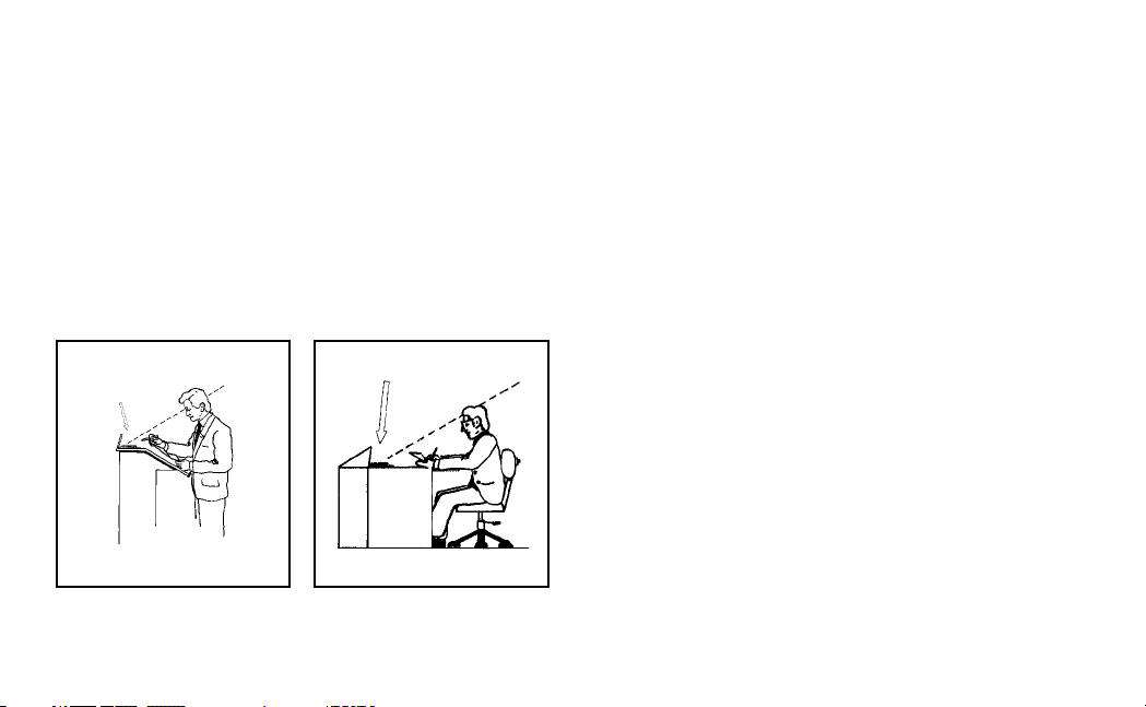
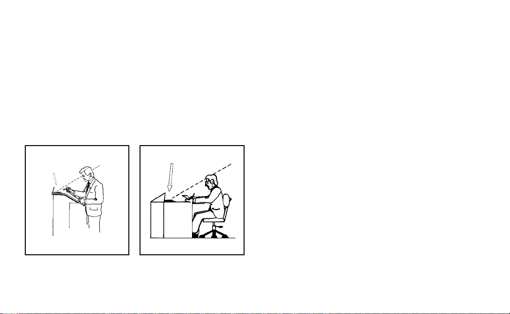
Die Auflagefläche (Tisch, Rednerpult o.ä.) begrenzt den Aufnahmewinkel,
das Mikrofon nimmt also nur Schall auf, der von oberhalb der Auflagefläche
eintrifft (s. Abb. 1 und 2, strichlierte Linien).
Die elastische Lagerung der Wandlerkapsel verhindert weitestgehend die
Übertragung von Klopfgeräuschen (Körperschall).
Dank des niederohmigen, elektronisch symmetrierten Ausgangs kann das
C 680 BL mit Phantomspeisung betrieben werden. Wenn Sie ein AKGSpeisegerät (B 18, N 62 E oder N 66 E) besitzen, können Sie das
C 680 BL sowohl an symmetrische als auch asymmetrische Eingänge anschließen. Der erforderliche Phantomspeiseadapter ist im Mikrofongehäuse
eingebaut.
Das C 680 BL wird mit einem fix montierten, 3 m langen Anschlußkabel
mit XLR-Stecker geliefert.
2. Anwendungshinweise
2.1. Positionierung
Legen sie das Mikrofon so auf den Konferenztisch bzw. das Rednerpult,
daß das Mikrofon mindestens 40 cm und höchstens 1 m vom Redner entfernt ist.
2.2. Fixe Montage
1. Befestigen Sie die mitgelieferten Klebestreifen an der Unterseite des
Mikrofons.
2. Entfernen Sie die Schutzfolie und drücken Sie das Mikrofon an der
gewünschten Stelle auf die Tischplatte.
Beim Entfernen des Mikrofons hinterlassen die Klebestreifen keine
Rückstände.
Abb. 1: Plazierung auf Rednerpulten Abb. 2: Plazierung auf Tischen
2
2.3. Umlackieren
Wenn Sie aus Gründen der Innenraumgestaltung das Mikrofon umlackieren
möchten, gehen Sie wie folgt vor:
1. Lösen Sie die beiden Kreuzschlitzschrauben an der Unterseite.
2. Nehmen Sie das Gehäuse ab.
3. Heben Sie das Gitter vorsichtig aus der Bodenplatte heraus.
4. Legen Sie das Gehäuse zum Lackieren auf einen Holzklotz, damit
der Gehäuserand nicht auf der Unterlage aufliegt.
Wichtig:
Lackieren Sie keinesfalls das Gitter! Der Lack verengt oder verstopft die
Löcher und verschlechtert dadurch die akustischen Eigenschaften des
Mikrofons erheblich.
3. Stromversorgung
Das C 680 BL ist ein Kondensatormikrofon und benötigt daher eine
Stromversorgung (”Phantomspeisung”).
Wenn Ihr Mischpult mit Phantomspeisung ausgestattet ist, schalten Sie diese
ein. (Lesen Sie dazu das entsprechende Kapitel der Betriebsanleitung des
Mischpults nach.)
3.1. Externe Speisegeräte
Wenn Ihr Mischpult keine Phantomspeisung besitzt, schalten Sie zwischen
Mikrofon und Mischpulteingang ein Phantomspeisegerät. Wir empfehlen
dazu die optionalen Netzgeräte N 62 E oder N 66 E sowie das (ebenfalls
optionale) Batteriespeisegerät B 18 von AKG. Wenn Sie andere als die
von AKG empfohlenen Speisegeräte verwenden, kann das Mikrofon
beschädigt werden und erlischt die Garantie.
3.2. Nachträglicher Einbau einer Phantomspeisung
Eine Phantomspeisung nach DIN 45596 kann auch nachträglich eingebaut
werden. Beachten Sie dabei unbedingt die Sicherheitshinweise und
Garantiebestimmungen in der Betriebsanleitung des Geräts, in das die
Phantomspeisung eingebaut werden soll.
3.2.1. Symmetrische Eingänge
Die DIN-Norm 45596 schreibt eine positive Spannung von 12, 24 oder
48 V an den NF-Leitungen gegen die Kabelabschirmung vor. Sie können
das Mikrofon aber auch mit allen Spannungen zwischen 9 und 52 V
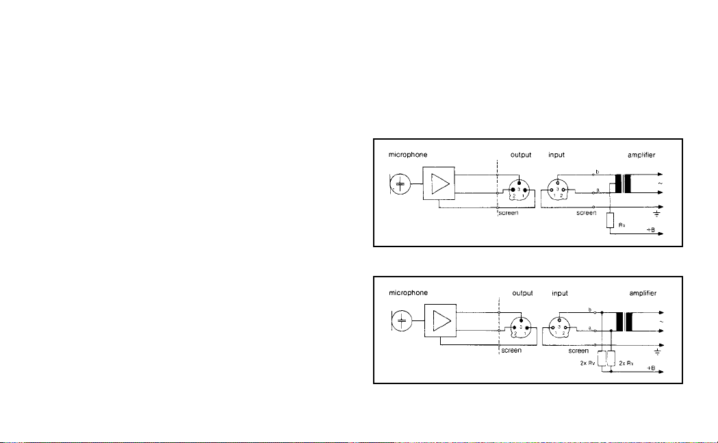
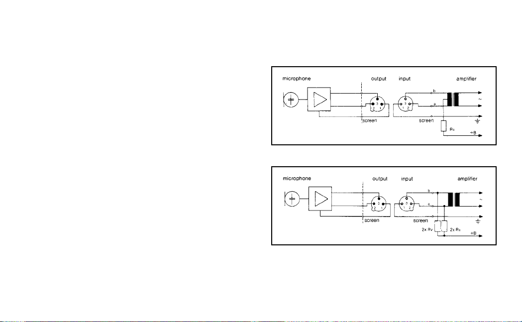
betreiben. Folgende Anschlußschemata werden empfohlen:
Abb. 3: Schaltung mit Eingangsübertrager mit Mittenanzapfung (erdfrei)
Abb. 4: Schaltung mit Eingangsübertrager ohne Mittenanzapfung (erdfrei)
3
Normwerte für Rv (bzw. 2 x Rv):
U= Rv 2 x Rv
12 V ±2 V 330 Ω ±10% 680 Ω ±10%
24 V ±4 V 680 Ω ±10% 1200 Ω ±10%
48 V ±4 V 3300 Ω ±10% 6800 Ω ±10%
Wichtig:
Um die Symmetrieanforderungen nach DIN 45596 zu erfüllen, dürfen die
Ist-Werte der Widerstände 2xRv um höchstens 0,4% voneinander abweichen.
3.2.2. Asymmetrische Eingänge
Sind die Geräteeingänge geerdet oder keine Eingangsübertrager vorhanden, fügen Sie entweder Kondensatoren oder zusätzliche
Transformatoren in die NF-Leitungen ein, um eine Beeinträchtigung der
Eingangsstufe durch Leckströme zu verhindern.
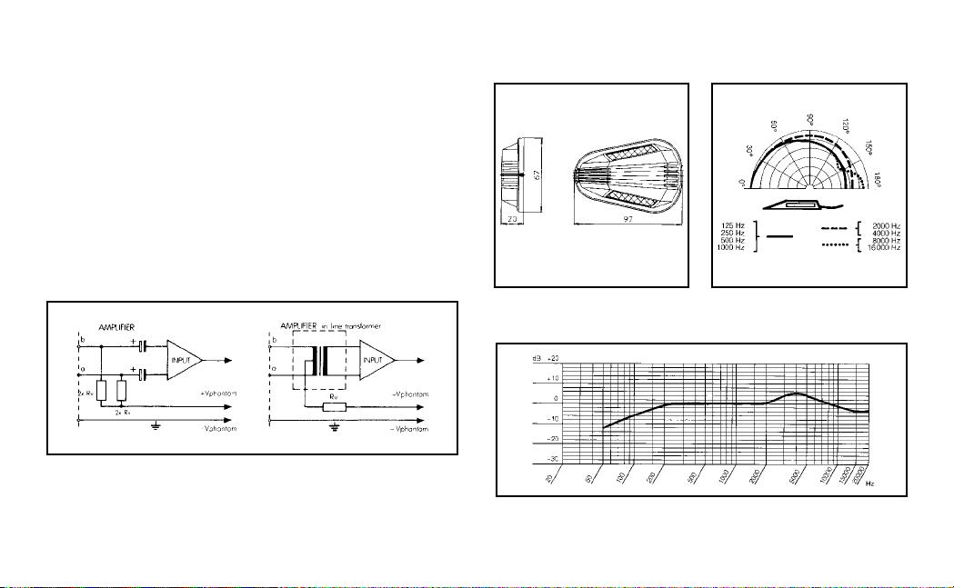
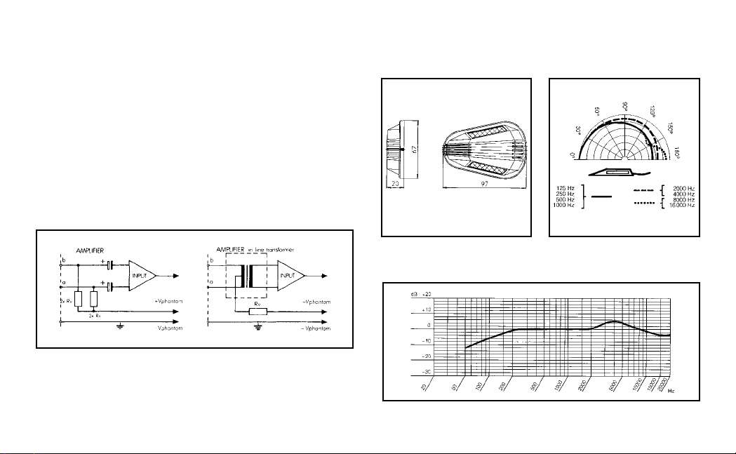
Abb. 5: Phantomspeisung bei asymmetrischen Eingängen
4. Reinigungshinweise
Reinigen Sie die Metalloberflächen mit (Industrie-)Spiritus oder Alkohol.
4
5. Maßzeichnung 6. Polardiagramm
7. Frequenzkurve

8. Technische Daten
8.1. Mikrofon
Arbeitsweise: Kondensatorwandler mit Permanent-Ladung
Richtcharakteristik: Niere
Übertragungsbereich: 60 bis 20.000 Hz
Empfindlichkeit bei 1000 Hz: 30 mV/Pa (-30 dBV)
Elektrische Impedanz: ≤200 Ω
Empfohlene Lastimpedanz: ≥2000 Ω
Grenzschalldruckpegel für 1% Klirrfaktor: 115 dB SPL
Geräuschpegelabstand bez. auf 1 Pa (A-bewertet): 67 dB(A)
Speisespannung: 9 bis 52 V DC laut DIN 45596
Stromaufnahme: ≤2 mA
Stecker: XLR, 3-polig
Länge des Anschlußkabels: 3 m
Abmessungen: 97 x 67 x 20 mm
Gewicht: ca 100 g netto (ohne Kabel und Stecker)
Dieses Produkt entspricht der Norm EN 50 082-1
8.2. Mitgeliefertes Zubehör
Fixes 3 m langes Anschlußkabel mit XLR-Stecker
2 Spezial-Klebestreifen
8.3. Empfohlenes Zubehör
Batteriespeisegerät B 18
Netzgerät zum Betrieb von zwei Mikrofonen N 62 E
5
Netzgerät zum Betrieb von sechs Mikrofonen N 66 E
1. Description
The C 680 BL is a cardioid condenser table microphone. Thanks to its small
dimensions, the C 680 BL can be placed so it will not distract the speaker.
When lying on a table or lectern the microphone element is very close to
a boundary. This design prevents any comb filter effects or other acoustic
interferences which would normally exist at microphone positions close to
reflecting surfaces.
The supporting surface (tabletop, lectern, etc.) limits the pickup area. In
other words, the microphone will only pick up sounds arriving from above
the table or lectern. (See the dashed lines in figs. 1 and 2.)
Fig. 1: Placement on a lectern. Fig. 2: Placement on a table.
6
A transducer shock mount prevents vibrational noise such as knocking or
footsteps from being picked up.
The microphone has a low-impedance, electronically balanced output
allowing it to be powered from phantom power sources. If you use an AKG
power supply (B 18, N 62 E, or N 66 E) you may connect the C 680 BL to
balanced or unbalanced inputs. The required phantom power adapter is
integrated in the microphone case.
The C 680 BL is fitted with a fixed, 3-m (10-ft.) cable with an XLR connector.
2. Uses
2.1. Placement
Place the microphone on the conference table or lectern so that the microphone will be at least 40 cm (16 in.) but no further than 1 m (40 in.) away
from the speaker’s mouth.
2.2. Permanent Installation
1. Fix the supplied adhesive strips to the underside of the microphone.
2. Remove the protective films from the adhesive strips and press the
microphone against the tabletop at the desired position.
The adhesive strips are non-tainting and you can remove the microphone at any time.
2.3. Repainting the C 680 BL
If you wish to blend the microphone in with the interior decoration of the
room you can repaint the C 680 BL as described below:
1. Remove the two Phillips screws from the underside of the microphone.
2. Remove the case.
3. Carefully lift the grid out of the bottom panel.
4. Place the case on a wood block to lift the edge of the case off the
workbench surface.
Ventilate the room and be sure to observe the instructions provided
by the paint manufacturer. When using spray paints, wear a respirator and use a spray booth.
Important:
Do not paint the grid. The paint would inevitably restrict or clog the holes
and thus severely degrade the acoustic performance of the microphone.
3. Powering
The C 680 BL is a condenser microphone and therefore needs a polarization
voltage (”phantom power”).
If your mixer provides phantom power, switch the phantom power on. (Refer
to the relevant section in your mixer manual.)
3.1. Using Optional Phantom Power Supplies
If your mixer has no phantom power, insert an external phantom power
supply between the microphone and mixer input. We recommend the
optional N 62 E or N 66 E AC power supplies or B 18 battery supply (also
optional) from AKG. Using any power supplies not recommended by
AKG may damage your microphone and voids the warranty.
3.2. Retrofitting Phantom Power
You may also consider retrofitting a phantom power supply as per DIN 45596
to your mixer. If you do so, be sure to observe the precautions and warranty conditions in the manual for the equipment in which you intend to
install the phantom supply.
3.2.1. Balanced Inputs
The DIN 45596 standard specifies a positive voltage of 12, 24, or 48 V on
the audio lines versus the cable shield. For balanced inputs, we recommend the following wiring schemes:
Fig. 3: Input transformer with center tap (ungrounded).
Fig. 4: Input transformer without center tap (ungrounded).
7
Standard values for Rv and 2 x Rv:
VDC Rv 2 x Rv
12 V ±2 V 330 Ω ±10% 680 Ω ±10%
24 V ±4 V 680 Ω ±10% 1,200 Ω ±10%
48 V ±4 V 3,300 Ω ±10% 6,800 Ω ±10%
Important:
In order to satisfy the DIN 45596 symmetry requirement, make sure the
actual values of the two resistors 2 x Rv do not differ by more than 0.4%!
3.2.2. Unbalanced Inputs
If the equipment inputs are grounded or transformerless, wire either
capacitors or extra transformers into the audio lines as shown below in order
to prevent any current leakage into the input stage.
Fig.5: Retrofitting phantom power to unbalanced inputs.
4. Cleaning
Clean all exterior surfaces with methylated spirits or alcohol.
8
5. Dimensional 6. Polar Diagram
Drawing
7. Frequency Response
 Loading...