

Page 1
C 5900
M
C 5900
Bedienungsanleitung. . . . . . . . . . . . S. 2
Bitte vor Inbetriebnahme des Gerätes lesen!
User Instructions. . . . . . . . . . . . . . p. 12
Please read the manual before using the equipment!
Mode d’emploi. . . . . . . . . . . . . . . . p. 22
Veuillez lire cette notice avant d’utiliser le système!
Istruzioni per l’uso. . . . . . . . . . . . . p. 32
Prima di utilizzare l’apparecchio, leggere il manuale
Modo de empleo . . . . . . . . . . . . . . p. 42
¡Sirvase leer el manual antes de utilizar el equipo!
Instruções de uso . . . . . . . . . . . . . p. 52
Por favor leia este manual antes de usar o equipamento!
M
/TM 40
Page 2
1 Sicherheitshinweis/Beschreibung
1.1 Sicherheitshinweis
1.2 Lieferumfang
1.3 Optionales
Zubehör
Überprüfen Sie bitte, ob das Gerät, an das Sie das Mikrofon
anschließen möchten, den gültigen Sicherheitsbestimmungen
entspricht und mit einer Sicherheitserdung versehen ist.
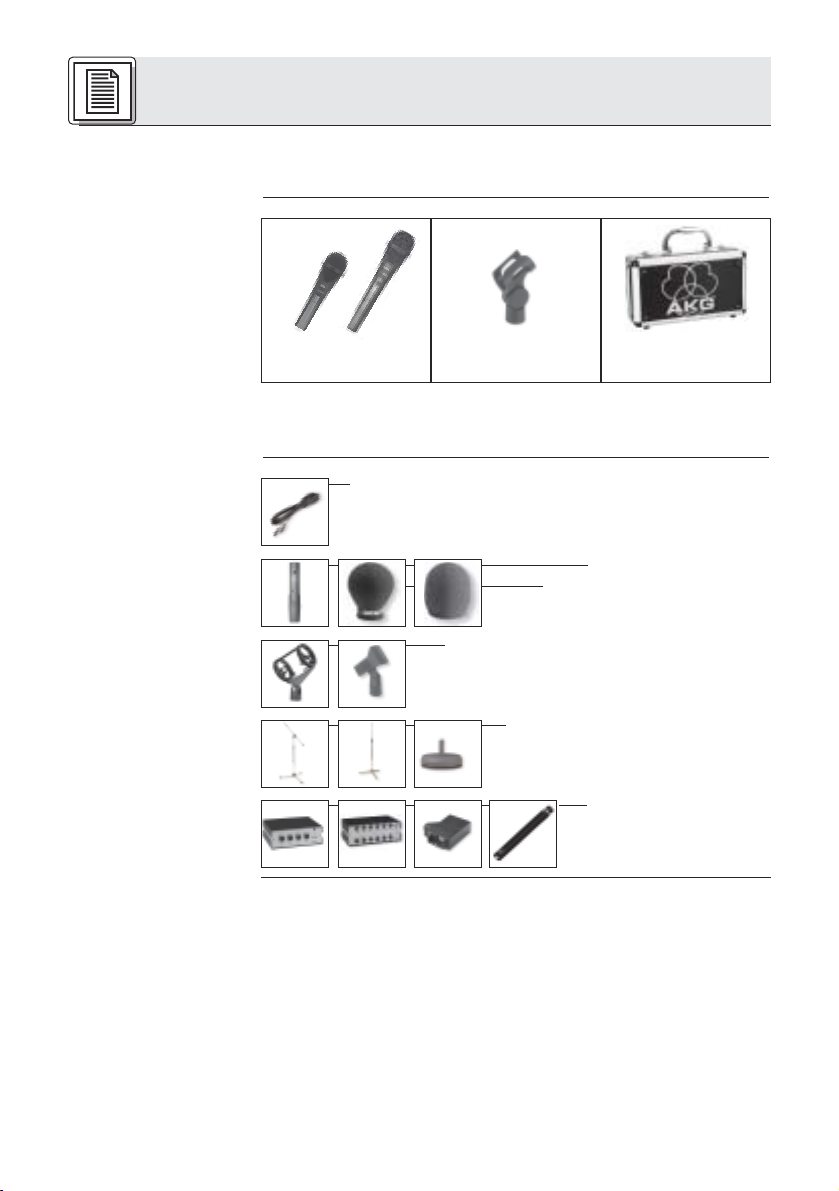
M
1 C 5900
oder C 5900M/TM 40
1 SA 61 1 Mikrofonkoffer
Kontrollieren Sie bitte, ob die Verpackung alle oben angeführten Teile enthält. Falls etwas fehlt, wenden Sie sich bitte an
Ihren AKG-Händler.
• Mikrofonkabel MK 9/10: 10 m 2-polig geschirmtes
Kabel mit XLR-Stecker und XLR-Kupplung
• Sendermodul TM 40,
• Windschutz W 23, W 3001
• Elastische Universal-Aufhängung H 30,
Stativanschluss SA 26
1.4 Besondere
Merkmale
2
• Bodenstative ST 102A, ST 200,
ST 305
• Phantomspeisegeräte
N 62, N 66, B 18, B 15
•Frequenzgang speziell für Gesangsübertragung ausgelegt.
•Integriertes Wind- und Popfilter unterdrückt wirkungsvoll
Pop- und Atemgeräusche.
• Schaltbares Bass Cut-Filter zur Unterdrückung tieffrequenter Störgeräusche.
• Schaltbare Anhebung des Ausgangspegels um 6 dB.
• Gute Rückkopplungsunterdrückung durch frequenzunabhängige supernierenförmige Richtwirkung.
• Brillante Übertragungsqualität durch Mikrofonkapsel in
Backplate-Kondensatortechnik.
Page 3
1 Beschreibung
• Eingebaute elastische Spinnenlagerung des Wandlersystems reduziert Griff- und Kabelgeräusche.
• Sicherer Schutz des Mikrofonwandlers durch nahezu undeformierbare Gitterkappe aus Federstahl
• Einbauschacht für optionales Sendermodul TM 40
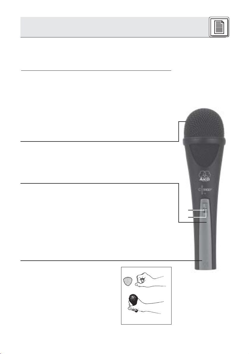
Das C 5900Mvon AKG ist ein Kondensatormikrofon mit supernierenförmiger Richtcharakteristik, konzipiert für den
Vokaleinsatz auf der Bühne. Eine leichte Anhebung der
Empfindlichkeit zwischen 3 und 15 kHz verschafft der Stimme
die nötige Durchsetzungskraft auch bei sehr hoher Lautstärke
auf der Bühne und sorgt für gute Textverständlichkeit.
Eine robuste, nahezu unverformbare Gitterkappe aus Federstahl und das stabile Zink-Alu-Druckgussgehäuse schützen
das Mikrofon und die Kapsel wirksam vor Beschädigungen im
harten Alltag "on the road".
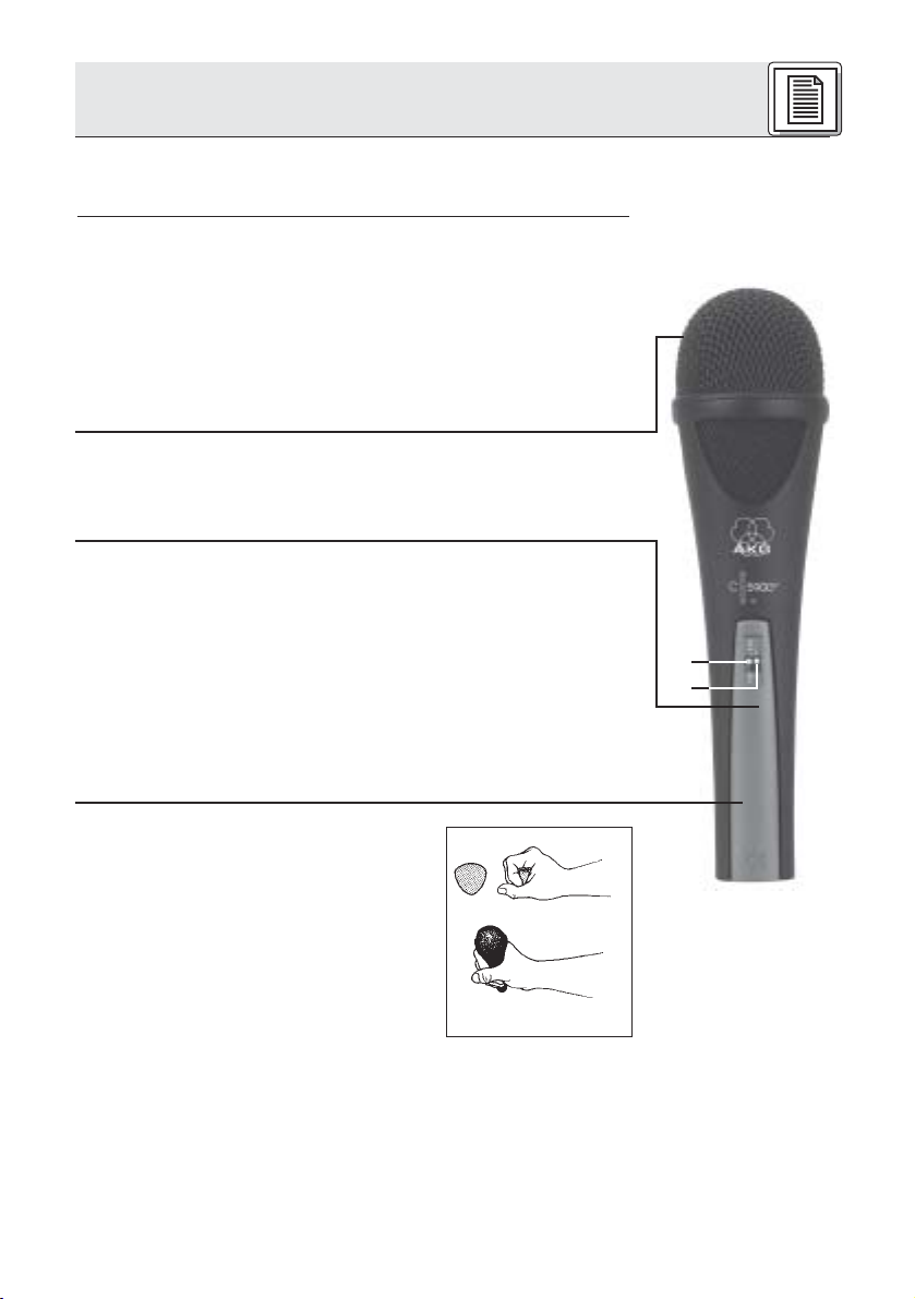
Ein Pegelumschalter (1) erlaubt Ihnen, den Ausgangspegel des
Mikrofons zur Anpassung an weniger empfindliche Eingänge
um 6 dB anzuheben.
Ein schaltbares Bass Cut-Filter (2) (-12 dB/Oktave ab 100 Hz)
ermöglicht eine wirksame Ausblendung tieffrequenter Störgeräusche.
Das Wandlersystem ist nach dem bewährten BackplateKondensatorprinzip aufgebaut. Ein dahinter liegender
Absorptionsring aus Synthetikkautschuk verhindert wie ein
schalltoter Raum das Entstehen von Reflexionen und damit
Veränderungen des Frequenzgangs. Hand- und Kabelgeräusche werden durch die integrierte Spinnenlagerung des
Wandlers weitgehend unterdrückt. Der Innenwindschutz reduziert
Pop-, Wind- und Atemgeräusche auf ein Minimum.
Das C 5900Mist mit einem abnehmbaren Anschlussmodul mit
3-poligem XLR-Stecker ausgestattet. Sie können das C 5900
sowohl an symmetrischen als auch asymmetrischen Mischpultund Verstärkereingängen betreiben.
1.5 C 5900M,
C 5900M/TM 40
1
2
M
Die ergonomisch optimierte Form des
Gehäuses gewährleistet absolute
Funktionalität und exzellente Anwenderfreundlichkeit. Sie haben das Mikrofon
stets voll im Griff, egal, wie Sie es einsetzen.
Abb. 1:
Ergonomisch
optimierte
Gehäuseform
3
Page 4
1 Beschreibung
Abb. 2: Optionales
Sendermodul TM 40
2 Anschluss
Sie können das Mikrofon auf einfache
Weise in ein Drahtlos-Mikrofon umwandeln, indem Sie das XLR-Steckermodul
ausbauen und durch das optionale
Sendermodul TM 40 ersetzen.
2.1 Allgemeines
Siehe Kapitel 2.2
und 2.3.
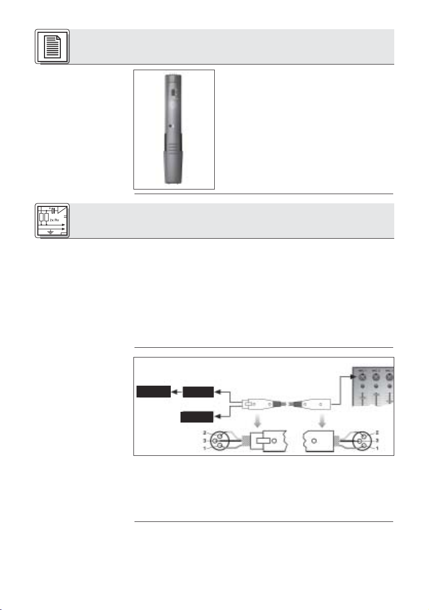
2.2 Eingang mit
Phantomspeisung
Abb. 3: Anschluss
an symmetrischen
Eingang
Siehe Abb. 3.
2.3 Eingang ohne
Phantomspeisung
Siehe Abb. 3.
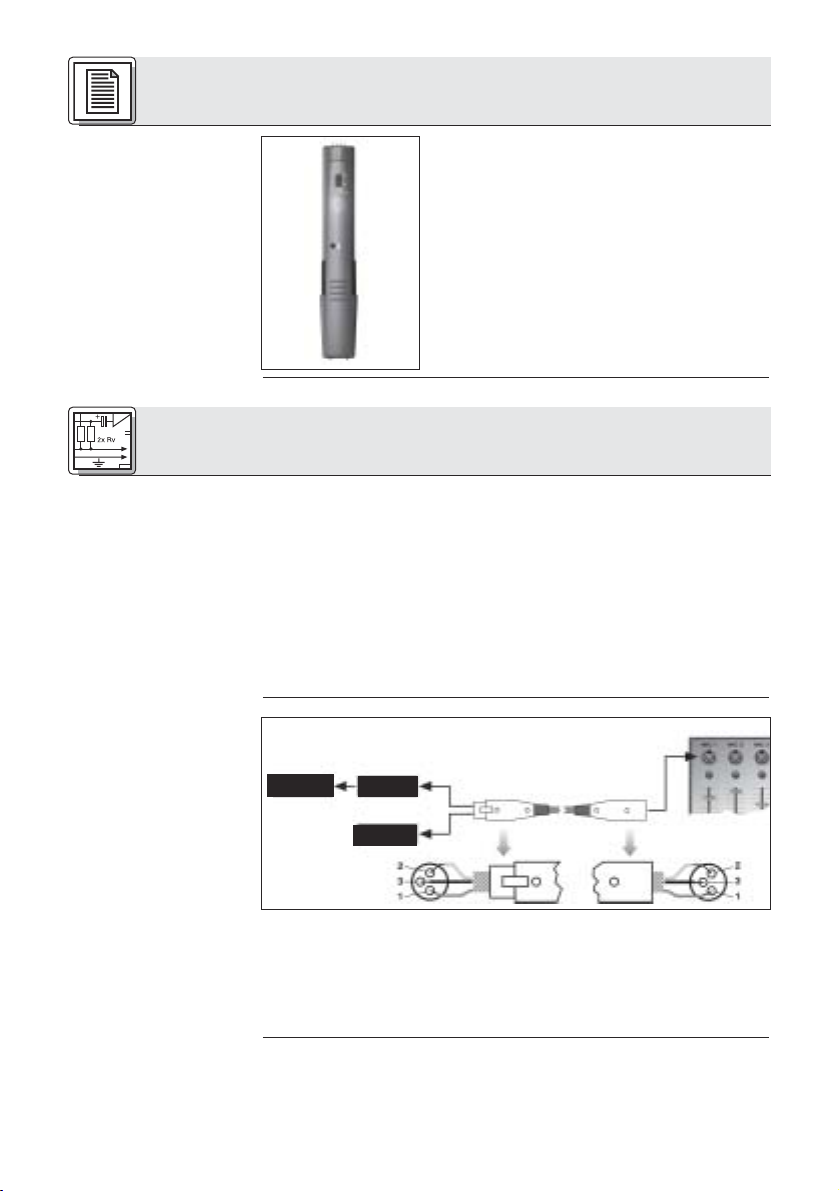
Das C 5900Mist ein Kondensatormikrofon und benötigt daher
eine Stromversorgung.
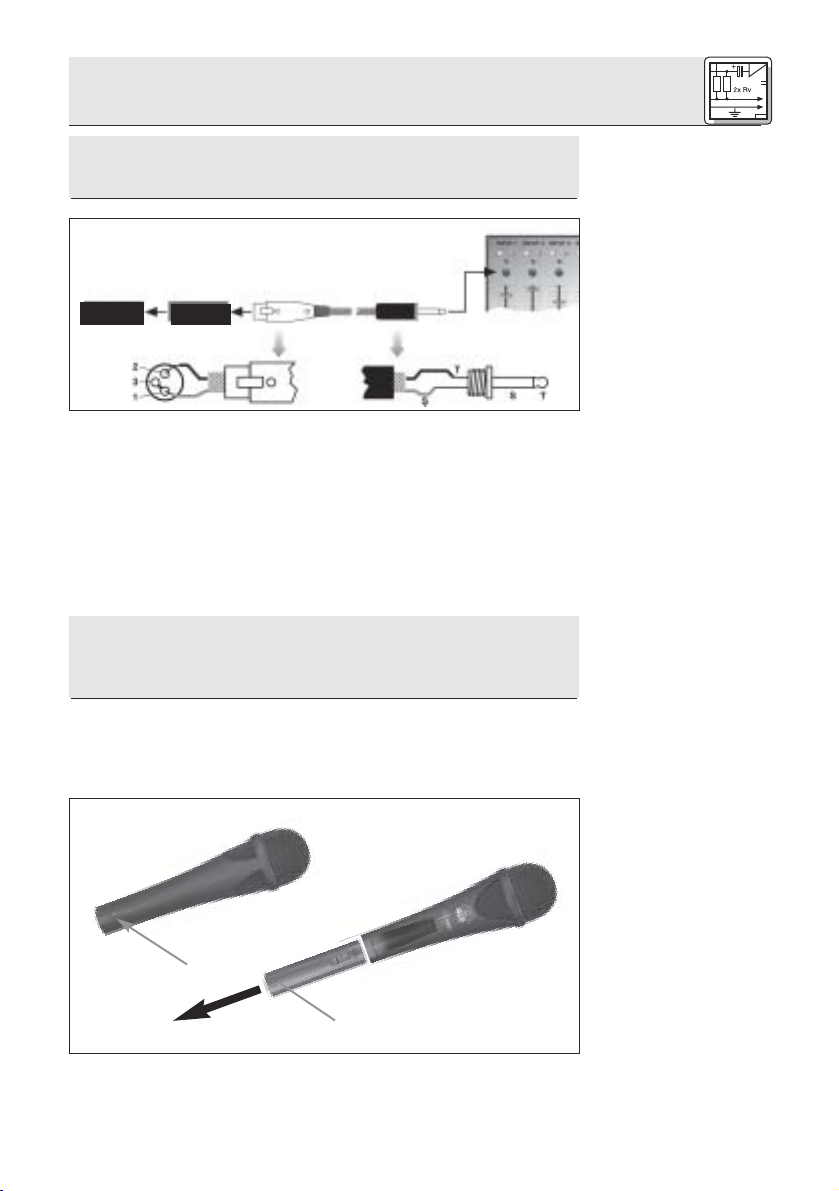
Das Mikrofon besitzt einen symmetrischen Ausgang mit 3-poligem XLR-Stecker:
Stift 1 = Masse
Stift 2 = Tonader (inphase)
Stift 3 = Tonader
Sie können das Mikrofon sowohl an symmetrische
Mikrofoneingänge mit oder ohne Phantomspeisung als auch an
asymmetrische Mikrofoneingänge anschließen.
C 5900
M
Phantom
C 5900
2.3
M
2.2
1. Schließen Sie das Mikrofon mit einem XLR-Mikrofonkabel
(z.B. dem optionalen MK 9/10 von AKG) an einen symmetrischen XLR-Mikrofoneingang mit Phantomspeisung an.
2. Schalten Sie die Phantomspeisung ein. (Lesen Sie dazu in
der Betriebsanleitung des jeweiligen Gerätes nach.)
1. Wenn Ihr Mischpult keine Phantomspeisung besitzt, schal-
ten Sie zwischen Mikrofon und Mischpulteingang ein AKGPhantomspeisegerät (N 62, N 66, B 18, B 15 - optional).
4
Page 5
2 Anschluss
Wenn Sie andere als die von AKG empfohlenen
Speisegeräte verwenden, kann das Mikrofon beschädigt
werden und erlischt die Garantie.
M
C 5900
Phantom
Die Phantomspeisegeräte von AKG können Sie auch an einen
asymmetrischen Eingang anschließen.
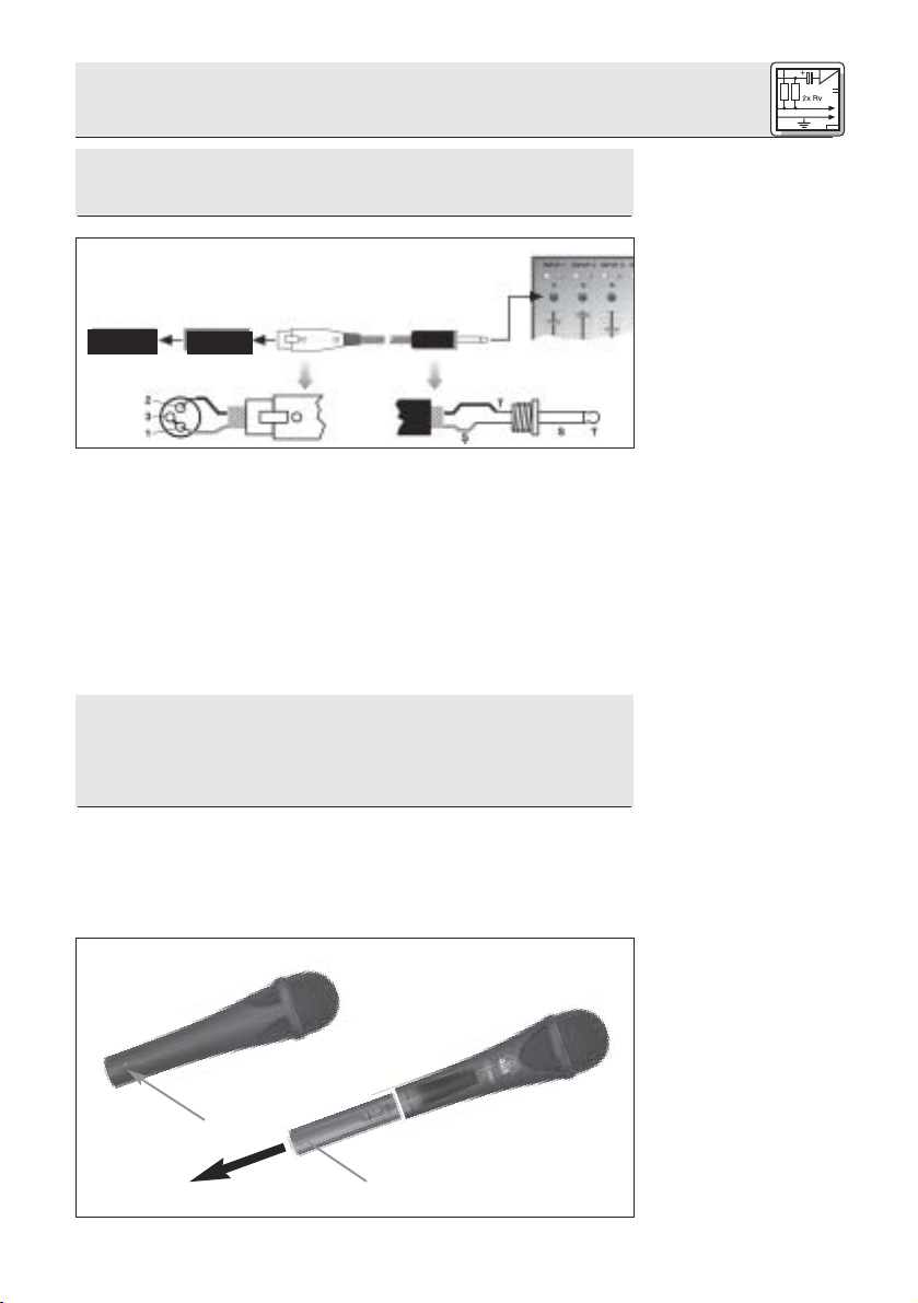
Verwenden Sie dazu ein Kabel mit XLR-Stecker (weiblich) und
Mono-Klinkenstecker:
1. Verbinden Sie im XLR-Stecker mittels einer Drahtbrücke
Stift 1 mit Stift 3 und mit der Abschirmung.
2. Verbinden Sie die innere Ader des Kabels mit Stift 2 des
XLR-Steckers und der Spitze des Klinkensteckers.
Beachten Sie, dass asymmetrische Kabel Einstreuungen aus
Magnetfeldern (von Netz- und Lichtkabeln, Elektromotoren
usw.) wie eine Antenne aufnehmen können . Bei Kabeln, die
länger als 5 m sind, kann dies zu Brumm- und ähnlichen Störgeräuschen führen.
Wichtig!
2.4
Asymmetrischer
Eingang
Abb. 4: Anschluss
an asymmetrischen
Eingang
Siehe Abb. 4.
Hinweis:
Mit dem optionalen Sendermodul TM 40 von AKG können Sie
Ihr Mikrofon jederzeit in ein Funkmikrofon verwandeln, das Sie
mit jedem Empfänger der Serie WMS 40 von AKG betreiben
können.
1
2
2.5 Optionales
Sendermodul
TM 40
Bauen Sie zuerst
das XLRSteckermodul aus:
Abb. 5: XLRSteckermodul
ausbauen
5
Page 6
2 Anschluss
Siehe Abb. 5.
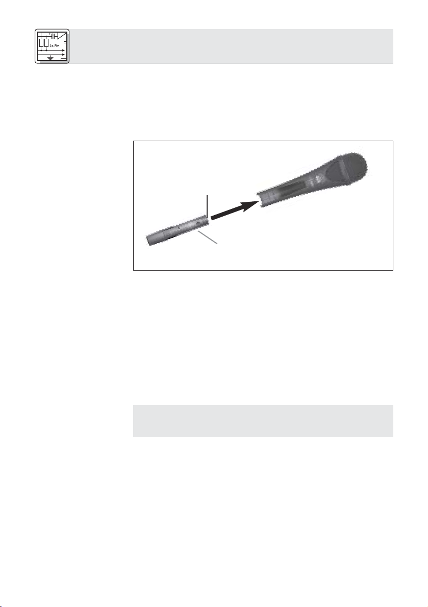
Bauen Sie das
Sendermodul ein:
Abb. 6:
Sendermodul
einbauen
Siehe Abb. 6.
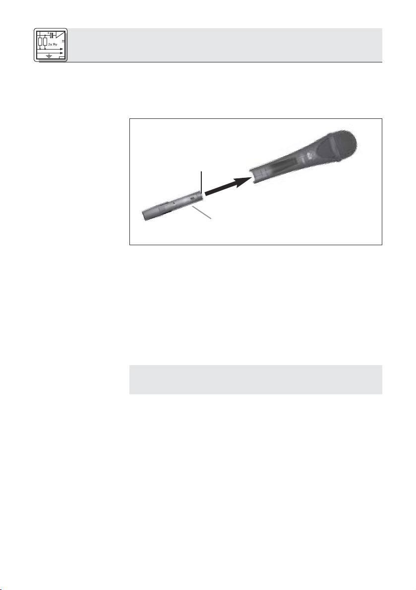
1. Öffnen Sie die Fixierungsschraube (1).
2. Ziehen Sie das XLR-Steckermodul (2) aus dem Mikrofonschaft heraus.
3. Damit Sie die Fixierungsschraube (1) nicht verlieren, drehen
Sie sie wieder in das Gewinde am XLR-Steckermodul hinein.
2
1
1. Vergessen Sie nicht, den Zustand der Batterie im Sendermodul zu kontrollieren. Legen Sie eine neue Batterie ein,
falls die derzeitige verbraucht ist oder sich gar keine
Batterie im Sendermodul befindet.
2. Halten Sie das Sendermodul (1) so, dass die Kontakte (2)
zum Mikrofon zeigen.
3. Schieben Sie das Sendermodul (1) so weit in den Mikrofonschaft hinein, bis das Sendermodul (1) hörbar einrastet.
Das Sendermodul verriegelt sich automatisch, die elektrischen Kontakte zum Mikrofon werden automatisch hergestellt.
Hinweis:
Wenn Sie das
Sendermodul
wieder gegen das
XLR-Steckermodul
austauschen
wollen:
Siehe Abb. 7.
6
Näheres zum Einlegen, Tauschen und Testen der Batterie
sowie zum Einstellen und Betrieb des Sendermoduls finden
Sie in der Bedienungsanleitung des Sendermoduls TM 40.
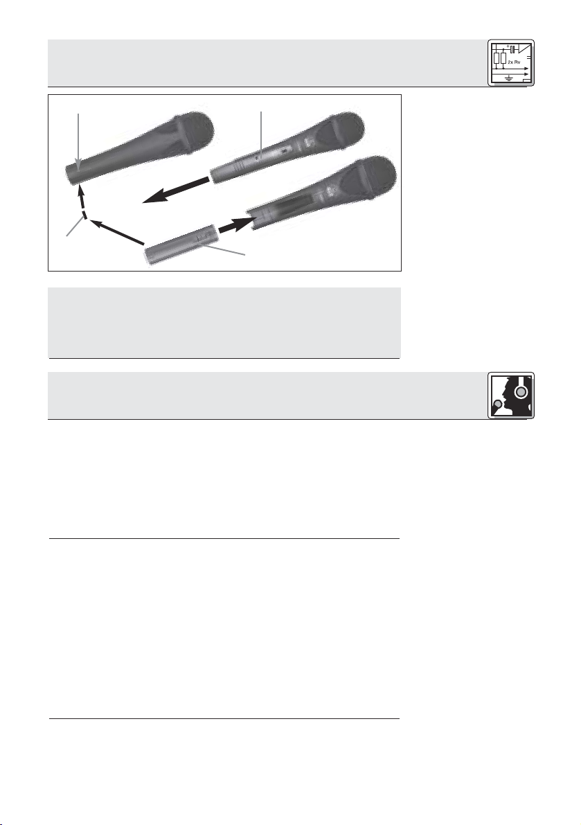
1. Führen Sie einen Kugelschreiber, kleinen Schraubenzieher
oder ähnlichen spitzen Gegenstand in die Öffnung (1) im
Mikrofonschaft ein und drücken Sie nach innen.
Das Sendermodul (2) wird entriegelt und gleitet ca. 2 mm
aus dem Mikrofonschaft heraus.
2. Ziehen Sie das Sendermodul (2) vom Mikrofon ab.
3. Drehen Sie die Fixierungsschraube (4) aus dem XLRSteckermodul (3) heraus.
4. Schieben Sie das XLR-Steckermodul (3) bis zum Anschlag
in den Mikrofonschacht hinein.
5. Fixieren Sie das XLR-Steckermodul (3), indem Sie die
Fixierungsschraube (4) fest anziehen.
Page 7

2 Anschluss
1
4
Sie können das Sendermodul auch ausbauen, indem Sie das
Sendermodul einfach nur kräftig aus dem Mikrofon herausziehen. Achten Sie darauf, das Sendermodul dabei nicht am
Batteriefachdeckel anzufassen. (Sie würden sonst lediglich das
Batteriefach öffnen.)
2
3
3 Anwendung
Ein Gesangsmikrofon bietet Ihnen viele Möglichkeiten, den
Klang Ihrer Stimme, wie er durch die Beschallungsanlage wiedergegeben wird, zu gestalten.
Beachten Sie bitte die folgenden Hinweise, um Ihr Mikrofon
optimal einsetzen zu können.
Die folgenden Kapitel gelten sowohl für die kabelgebundene
Ausführung des C 5900
bautem optionalem Sendermodul TM 40.
M
als auch für das Mikrofon mit einge-
Abb. 7:
Sendermodul
ausbauen
Hinweis:
3.1 Einleitung
Grundsätzlich wird Ihre Stimme umso voller und weicher wiedergegeben, je kürzer der Abstand zwischen den Lippen und
dem Mikrofon ist, während bei größerer Mikrofondistanz ein
halligeres, entfernteres Klangbild zustande kommt, da die
Akustik des Raumes mehr zur Geltung kommt.
Sie können daher Ihre Stimme aggressiv, neutral oder einschmeichelnd klingen lassen, indem Sie den Mikrofonabstand verändern.
Der Neheffekt tritt im unmittelbaren Nahbereich der
Schallquelle (weniger als 5 cm) auf und bewirkt eine starke
Betonung der Tiefen. Er verleiht Ihrer Stimme einen voluminöseren, intimen, bassbetonten Klang.
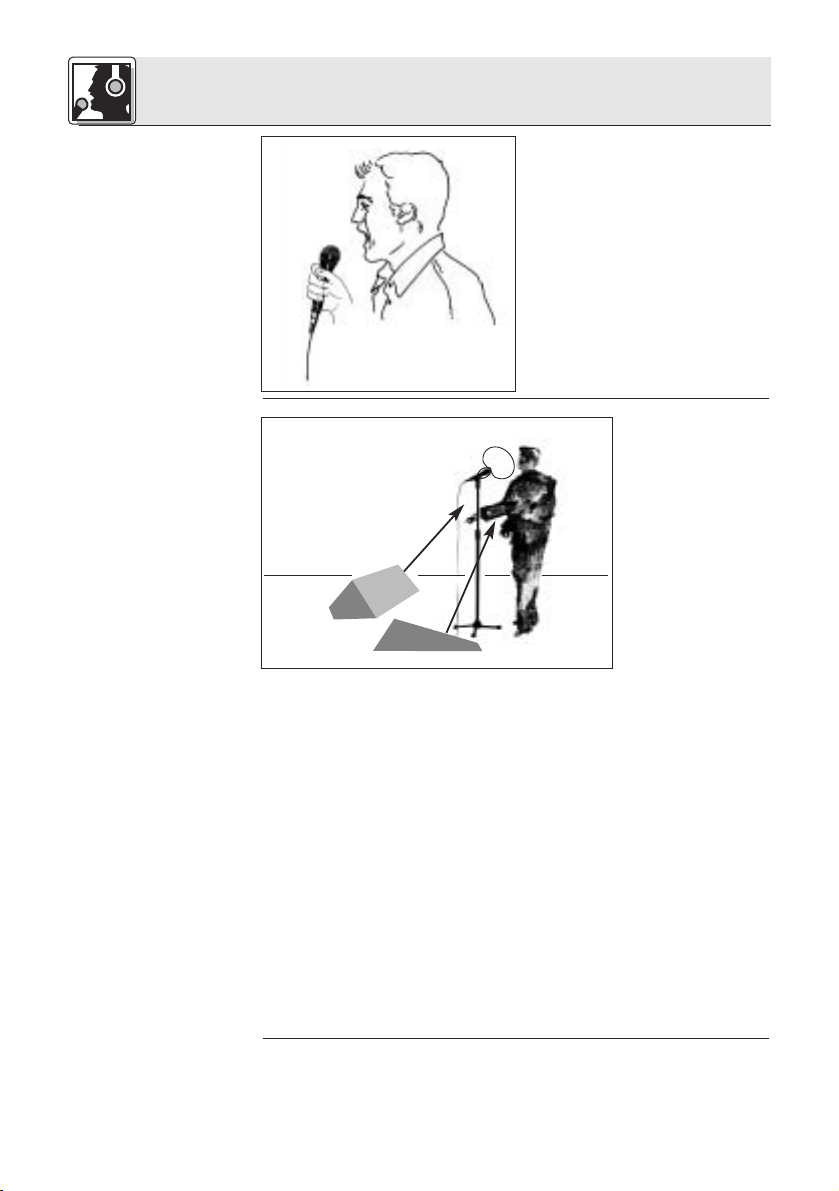
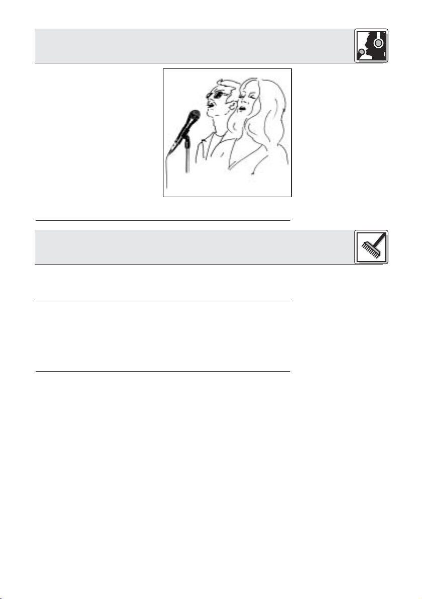
Singen Sie seitlich auf das Mikrofon oder über den Mikrofonkopf hinweg. So erhalten Sie einen ausgewogenen, naturgetreuen Klang.
3.2
Besprechungsabstand und
Naheffekt
3.3 Schalleinfallswinkel
Siehe Abb. 8.
7
Page 8
3 Anwendung
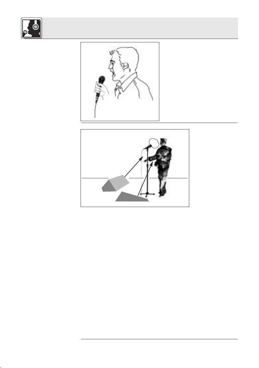
Abb. 8: Typische
Mikrofonposition
Wenn Sie direkt von vorne auf
das Mikrofon singen, werden
nicht nur Atemgeräusche mitübertragen, sondern auch
Verschlusslaute (p, t) und
Zischlaute (s, sch, tsch) unnatürlich hervorgehoben.
3.4 Rückkopplung
Abb. 9:
Mikrofonaufstellung
für minimale
Rückkopplung
Siehe Abb. 9.
Die Rückkopplung
kommt dadurch
zustande, dass
ein Teil des von
den Lautsprechern
abgegebenen
Schalls vom Mikrofon aufgenommen
und verstärkt
wieder den Lautsprechern zugeleitet wird. Ab einer
bestimmten
Lautstärke (der Rückkopplungsgrenze) läuft dieses Signal
gewissermaßen im Kreis, die Anlage heult und pfeift und kann
nur durch Zurückdrehen des Lautstärkereglers wieder unter
Kontrolle gebracht werden.
Um dieser Gefahr zu begegnen, hat das Mikrofon eine supernierenförmige Richtcharakteristik. Das bedeutet, dass es für
Schall, der von vorne einfällt (die Stimme) am empfindlichsten
ist, während es auf seitlich einfallenden Schall oder Schall, der
von hinten auftrifft (z.B. von Monitorlautsprechern), kaum
anspricht.
Minimale Rückkopplungsneigung erreichen Sie, indem Sie die
PA-Lautsprecher vor den Mikrofonen (am vorderen Bühnenrand) aufstellen.
Wenn Sie Monitorlautsprecher verwenden, lassen Sie Ihr
Mikrofon nie direkt auf die Monitore oder die PA-Lautsprecher
zeigen.
Rückkopplung kann auch durch Resonanzerscheinungen (als
Folge der Raumakustik), besonders im unteren Frequenzbereich, ausgelöst werden, also indirekt durch den Naheffekt. In
diesem Fall brauchen Sie oft nur den Mikrofonabstand zu vergrößern, um die Rückkopplung zum Abreissen zu bringen.
8
Page 9
3 Anwendung
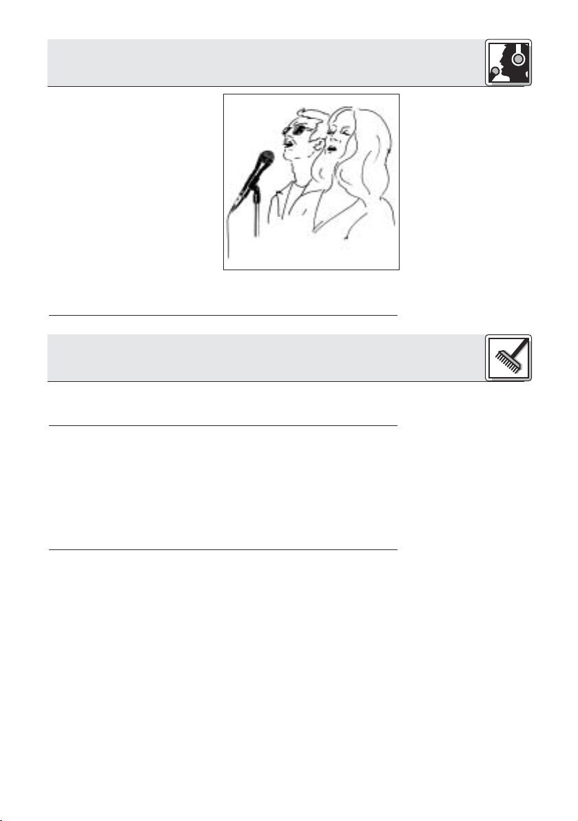
1. Lassen Sie nie mehr als
zwei Personen in ein
gemeinsames Mikrofon
singen.
2. Achten Sie darauf, dass
der Schalleinfallswinkel nie
größer als 35° ist.
Das Mikrofon ist für seitlich einfallenden Schall
sehr unempfindlich. Wenn
die beiden VokalistInnen
aus einem größeren Winkel als 35° auf das Mikrofon singen, müssten Sie den Pegelregler des Mikrofonkanals so weit aufziehen, dass die Rückkopplungsgefahr zu
groß würde.
4 Reinigung
Reinigen Sie die Gehäuseoberfläche des Mikrofons mit einem
mit Wasser befeuchteten Tuch.
1. Schrauben Sie die Gitterkappe des Mikrofons gegen den
Uhrzeigersinn ab.
2. Nehmen Sie den Windschutz aus der Gitterkappe heraus
und reinigen Sie den Windschutz mit Seifenwasser.
3. Lassen Sie den Windschutz über Nacht trocknen.
4. Legen Sie den Windschutz in die Gitterkappe ein und
schrauben Sie die Gitterkappe im Uhrzeigersinn auf das
Mikrofon auf.
3.5 Begleitchor
Abb. 10:
Mikrofonaufstellung
für Begleitduo
4.1 Gehäuseoberfläche
4.2 Innenwindschutz
9
Page 10
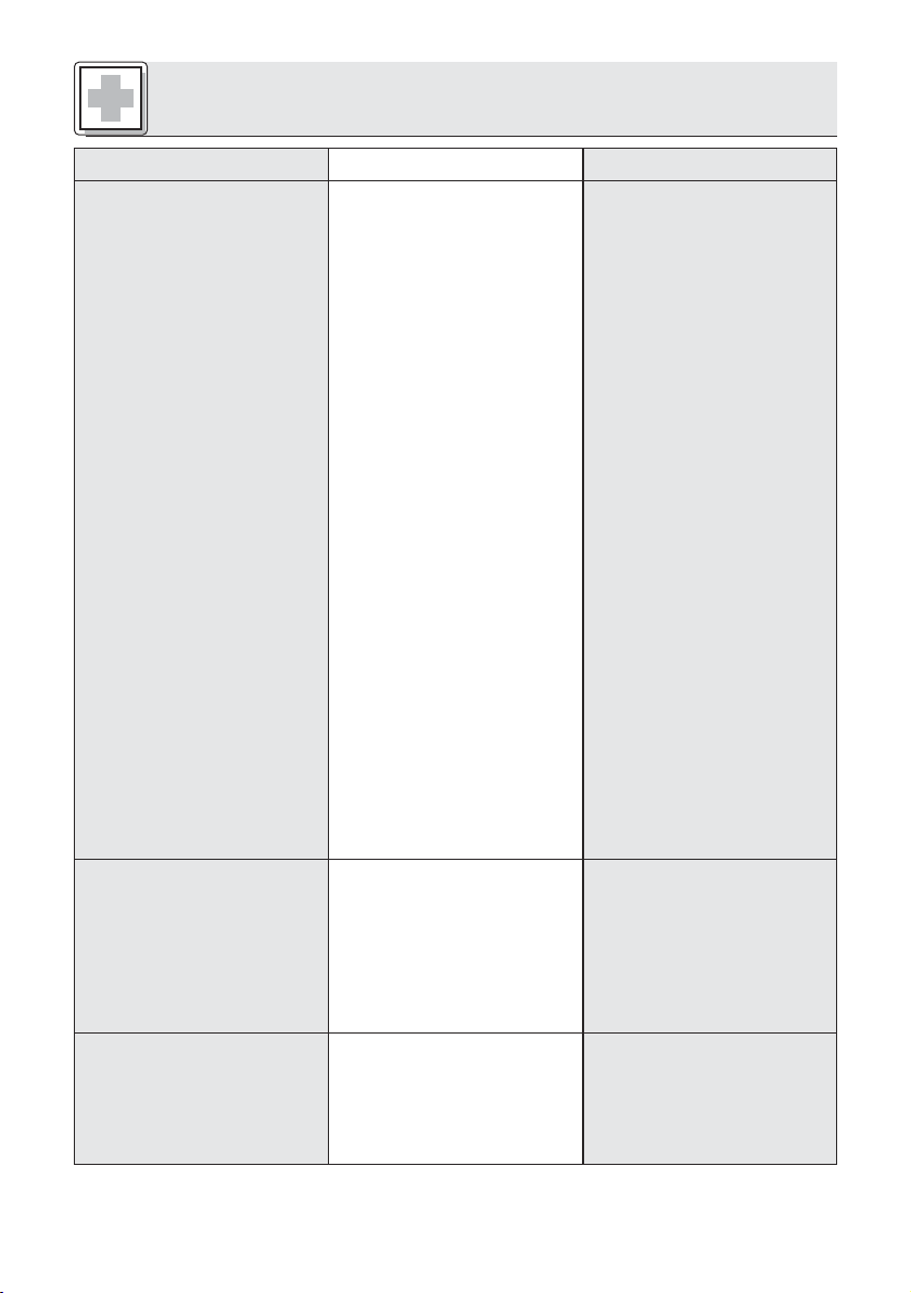
5 Fehlerbehebung
Fehler
Kein Ton.
Mögliche Ursache Abhilfe
1. Mischpult und/oder
Verstärker ausgeschaltet.
2. Kanal- oder SummenFader am Mischpult
oder Lautstärkeregler
des Verstärkers steht
auf Null.
3. Mikrofon nicht an
Mischpult oder Verstärker
angeschlossen.
4. Kabelstecker nicht
richtig angesteckt.
5. Kabel defekt.
6. Keine Speisespannung.
7. Sendermodul aus- oder
stummgeschaltet.
8. Keine/leere Batterie im
Sendermodul.
9. Empfänger ausgeschaltet/nicht ans Mischpult
angeschlossen.
1. Mischpult und/oder
Verstärker einschalten.
2. Kanal-oder SummenFader am Mischpult
oder Lautstärkeregler
des Verstärkers auf
gewünschten Pegel
einstellen.
3. Mikrofon an Mischpult
oder Verstärker anschließen.
4. Kabelstecker nochmals
anstecken.
5. Kabel überprüfen und
falls nötig ersetzen.
6. Phantomspeisung einschalten.
Phantomspeisegerät:
ans Netz anschließen
bzw. Batterie(n) einlegen.
Kabel überprüfen und
falls nötig ersetzen.
7. Sendermodul einschalten.
8. Volle Batterie in
Sendermodul einlegen.
9. Empfänger
einschalten/an das
Mischpult anschließen.
Verzerrungen.
Mikrofon klingt mit der
Zeit immer dumpfer.
10
1. Gain-Regler am
Mischpult oder
Sendermodul nicht richtig eingestellt.
2. Mischpulteingang zu
empfindlich.
•Verschmutzter
Innenwindschutz oder
Aussenwindschutz
dämpft hohe
Frequenzen.
1. Gain-Regler so einstellen, dass Verzerrungen
verschwinden.
2. 10-dB-Vorabschwächung
zwischen Mikrofonkabel
und Eingang stecken.
• Innenwindschutz bzw.
Aussenwindschutz
reinigen.
Page 11
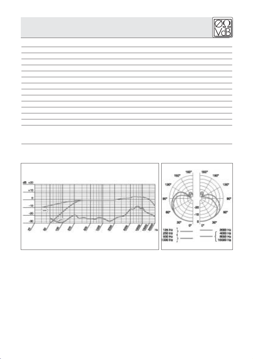
6 Technische Daten
Arbeitsweise: Kondensatormikrofon
Richtcharakteristik: Superniere
Übertragungsbereich: 20-20.000 Hz
Empfindlichkeit: 6 mV/Pa (-44 dBV bez. auf 1 V/Pa)
Elektrische Impedanz bei 1000 Hz: ≤200 Ω
Empfohlene Lastimpedanz: ≥2000 Ω
Grenzschalldruckpegel für 1% / 3% Klirrfaktor: 139 / 142 dB SPL
Äquivalentschalldruckpegel: 17,5 dB (A) (nach DIN 45412)
Speisespannung: 9 - 52 V Universal-Phantomspeisung
Stromaufnahme: ca. 2 mA
Steckerart: XLR 3-polig
Oberfläche: mattschwarz
Abmessungen: L: 186 mm; ø: 50 mm
Gewicht (netto/brutto): 290 g / 970 g
Dieses Produkt entspricht der Norm EN 50 082-1, vorausgesetzt, dass nachgeschaltete Geräte CE-konform sind.
Frequenzgang Polardiagramm
11
Page 12

1 Precaution/Description
1.1 Precaution
1.2 Unpacking
1.3 Optional
Accessories
Please make sure that the piece of equipment your microphone
will be connected to fulfills the safety regulations in force in your
country and is fitted with a ground lead.
M
1 C 5900
or C 5900M/TM 40
1 SA 61 1 Carrying case
Check that the packaging contains all of the components listed
above. Should anything be missing, please contact your AKG
dealer.
• MK 9/10 microphone cable: 10 m (30 ft.)
2-conductor shielded cable with 3-pin male and
3-contact female XLR connectors
• TM 40 transmitter module
• W 23, W 3001 windscreens
• H 30 universal elastic suspension,
SA 26 stand adapter
12
1.4 Features
• ST 102A, ST 200, ST 305
floor stands
• N 62, N 66, B 18, B 15
phantom power supplies
•Frequency response tailored to vocal use.
•Integrated wind and pop screen for effective suppression of
pop and breath noise.
• Switchable bass cut filter for suppression of low-frequency
rumble.
• Selectable 0 dB or +6 dB output level.
•Frequency independent supercardioid polar pattern for high
gain before feedback.
• Backplate condenser transducer for crisp sound.
• Built-in spider type transducer shock mount for handling
and cable noise compensation.
Page 13
1 Description
• Extremely resilient, spring-steel wire-mesh cap for extra
impact resistance.
• Installation slot for optional TM 40 transmitter module.
The AKG C 5900Mis a supercardioid condenser microphone
designed for vocal use on stage. A slight sensitivity peak
between 3 kHz and 15 kHz provides good intelligibility and will
make your voice cut through the loudest mix on stage.
A rugged front grill made of spring-steel wire mesh that is
extremely resistant to deformation and a sturdy zinc alloy diecast body effectively protect the microphone and transducer
element from damage on stage and on the road.
A level selector (1) allows you to boost the microphone's output
level by 6 dB to match the signal level to less sensitive inputs.
A switchable bass cut filter (2) (-12 dB/octave from 100 Hz)
effectively reduces low-frequency rumble.
The microphone element uses a proven backplate condenser
transducer. Similar to an anechoic chamber, an absorption ring
of synthetic rubber at the back of the capsule prevents reflections within the capsule that might degrade the frequency
response. An integrated spider type shock mount on the transducer element effectively suppresses handling and cable noise.
An internal windscreen reduces pop, wind, and breath noise to
a minimum.
The C 5900
M
features a removable connection module with a 3pin XLR connector. You can connect the microphone to both
balanced and unbalanced mixer or amplifier inputs.
The microphone body has been specifically designed for fatigue-free handling
and ease of use. No matter what microphone technique you use, the microphone will always settle comfortably into
your hand.
1.5 C 5900M,
C 5900M/TM 40
1
2
Fig. 1:
Ergonomically
optimized shape.
13
Page 14
1 Description
Fig. 2: Optional
TM 40 transmitter
module.
2 Interfacing
You can easily convert the microphone
into a wireless microphone. All you need
to do is remove the XLR connector module and replace it with an optional TM 40
transmitter module.
2.1 General
Refer to sections
2.2 and 2.3.
2.2 Input with
Phantom Power
Fig. 3: Connecting
to a balanced input.
Refer to fig. 3.
2.3 Input with No
Phantom Power
Refer to fig. 3.
The C 5900Mis a condenser microphone and therefore needs a
power supply.
The microphone provides a balanced output on a 3-pin male
XLR connector:
Pin 1: ground
Pin 2: hot
Pin 3: return
You can connect the microphone either to a balanced microphone input with or without phantom power or an unbalanced
microphone input.
C 5900
M
Phantom
C 5900
2.3
M
2.2
1. Use an XLR cable (e.g., the optional MK 9/10 from AKG) to
connect the microphone to a balanced XLR input with
phantom power.
2. Switch the phantom power on. (Refer to the manual of the
unit to which you connected your microphone.)
1. If your mixer provides no phantom power, connect an
optional AKG phantom power supply (N 62 E, N 66 E, B 18,
B 15) between the microphone and the mixer.
14
Page 15
2 Interfacing
Using any power supply other than those recommended
by AKG may damage your microphone and will void the
warranty.
M
C 5900
Phantom
You may connect AKG phantom power supplies to unbalanced
inputs, too.
Use a cable with a female XLR connector and TS jack plug:
1. On the XLR connector, use a wire bridge to connect pin 1 to
pin 3 and the cable shield.
2. Connect the inside wire of the cable to pin 2 on the XLR
connector and the tip contact of the jack plug.
Unbalanced cables may pick up interference from stray magnetic fields near power or lighting cables, electric motors, etc.
like an antenna. This may introduce hum or similar noise when
you use a cable that is longer than 16 feet (5 m).
Important!
2.4 Unbalanced
Input
Fig. 4: Connecting
to an unbalanced
input.
Refer to fig. 4.
Note:
The optional TM 40 transmitter module allows you to convert
your microphone into a wireless microphone that you can use
with any WMS 40 Series receiver from AKG.
1
2
1. Open the fixing screw (1).
2.5 Optional
TM 40 Transmitter
Module
Start by removing
the XLR connector module:
Fig. 5: Removing
the XLR connector
module.
Refer to fig. 5.
15
Page 16
2 Interfacing
Refer to fig. 5.
Install the trans-
mitter module:
Fig. 6: Installing the
transmitter module.
Refer to fig. 6.
2. Pull the XLR connector module (2) out of the microphone
body.
3. To avoid losing the fixing screw (1), screw it into the threaded hole (3) in the XLR connector module.
2
1
1. Do not forget to check the condition of the battery inside the
transmitter module. If the battery is dead or there is no battery inside the transmitter module, insert a new battery.
2. Hold the transmitter module (1) to align the contacts (2) with
the microphone.
3. Slide the transmitter module (1) into the microphone body to
the point that the transmitter module (1) will lock with an
audible click.
As the transmitter module locks in place, the electrical connections to the microphone are made automatically.
Replacing the
transmitter
module with the
XLR connector
module:
Refer to fig. 7.
16
Note:
For details on inserting, replacing, and testing the battery as
well as setting up and operating the transmitter module
refer to the TM 40 transmitter module manual.
1. Insert a ball point pen, small screwdriver, or similar pointed
object into the opening (1) in the microphone body and
press inward.
The transmitter module (2) will unlock and slide out of the
microphone body for about 0.1 inch.
2. Pull the transmitter module (2) out of the microphone.
3. Unscrew the fixing screw (4) from the XLR connector module (3).
4. Slide the XLR connector module (3) into the microphone
body to the stop.
5. To fix the XLR connector module (3), screw the fixing screw
(4) down firmly.
Page 17
2 Interfacing
1
4
Alternatively, you can remove the transmitter module simply by
pulling it out of the microphone body with just enough force to
unlock it. Make sure not to grasp the transmitter module by the
battery compartment. (If you did, you would only open the battery compartment.)
2
3
3 Using Your Microphone
A handheld vocal microphone provides many ways of shaping
the sound of your voice as it is heard over the sound system.
The following sections contain useful hints on how to use your
microphone for best results.
The following sections apply to both the hardwire C 5900
the wireless version with an optional TM 40 transmitter module
installed.
M
and
Fig. 7: Removing
the transmitter
module.
Note:
3.1 Introduction
Basically, your voice will sound the bigger and mellower, the
closer you hold the microphone to your lips. Moving away from
the microphone will produce a more reverberant, more distant
sound as the microphone will pick more of the room’s reverberation.
You can use this effect to make your voice sound aggressive,
neutral, insinuating, etc. simply by changing your working distance.
Proximity effect is a more or less dramatic boost of low frequencies that occurs when you sing into the microphone from
less than 2 inches. It gives more "body" to your voice and an
intimate, bass-heavy sound.
3.2 Working
Distance and
Proximity Effect
17
Page 18
3 Using Your Microphone
3.3 Angle of
Incidence
Fig. 8: Typical
microphone
position.
3.4 Feedback
Fig. 9: Microphone
placement for maxi-
mum gain before
feedback.
Refer to fig. 9.
Sing to one side of the microphone or above and across
the microphone’s top. This
provides a well-balanced, natural sound.
If you sing directly into the
microphone, it will not only
pick up excessive breath
noise but also overemphasize
"sss", "sh", "tch", "p", and "t"
sounds.
Feedback is the
result of part of
the sound projected by a speaker
being picked up
by a microphone,
fed to the amplifier, and projected
again by the
speaker. Above a
specific volume or
"system gain"
setting called
the feedback threshold, the signal starts being regenerated
indefinitely, making the sound system howl and the sound
engineer desperately dive for the master fader to reduce the
volume and stop the howling.
To increase usable gain before feedback, the microphone has a
supercardioid polar pattern. This means that the microphone is
most sensitive to sounds arriving from in front of it (your voice)
while picking up much less of sounds arriving from the sides or
rear (from monitor speakers for instance).main ("FOH") speakers in front of the microphones (along the front edge of the
stage).
If you use monitor speakers, be sure never to point any microphone directly at the monitors, or at the FOH speakers.
Feedback may also be triggered by resonances depending on
the acoustics of the room or hall. With resonances at low frequencies, proximity effect may cause feedback. In this case, it
is often enough to move away from the microphone a little to
stop the feedback.
18
Page 19
3 Using Your Microphone
1. Never let more than two
persons share a microphone.
2. Ask your backing vocalists
never to sing more than 35
degrees off the microphone axis.
The microphone is very
insensitive to off-axis
sounds. If the two vocalists were to sing into the
microphone from a wider
angle than 35 degrees,
you may end up bringing up the fader of the microphone
channel far enough to create a feedback problem.
4 Cleaning
To clean the surface of the microphone body, use a soft cloth
moistened with water.
1. Unscrew the front grill from the microphone CCW.
2. Remove the windscreen from the from grill and wash the
windscreen in soap suds.
3. Allow the windscreen to dry overnight.
4. Replace the windscreen in the front grill and screw the front
grill on the microphone CW.
3.5 Backing
Vocals
Fig. 10: Two vocalists sharing a microphone.
4.1 Microphone
Body
4.2 Internal
Windscreen
19
Page 20
5 Troubleshooting
Problem
No sound.
Possible Cause Remedy
1. Power to mixer and/or
amplifier is off.
2. Channel or master fader
on mixer, or volume
control on amplifier is at
zero.
3. Microphone is not connected to mixer or
amplifier.
4. Cable connectors are
seated loosely.
5. Cable is defective.
6. No supply voltage.
7. Transmitter module is off
or muted.
8. No/dead battery in
transmitter module.
9. Receiver is off or not
connected to mixer.
1. Switch power to mixer
or amplifier on.
2. Set channel or master
fader on mixer or volume control on amplifier
to desired level.
3. Connect microphone to
mixer or amplifier.
4. Check cable connectors
for secure seat.
5. Check cable and
replace if damaged.
6. Switch phantom power
on.
Phantom power supply:
connect to power outlet
or insert battery (batteries).
Check cable and
replace if necessary.
7. Switch transmitter module on.
8. Insert new/fully charged
battery.
9. Switch receiver on or
connect to mixer.
Distortion.
Microphone sound
becomes duller
by and by.
20
1. Gain control on mixer or
transmitter module not
set correctly.
2. Mixer input sensitivity
too high.
• Internal or external
windscreen attenuates
high frequencies when
soiled.
1. Set gain control to stop
distortion.
2. Insert 10 dB preattenuation pad between microphone cable and input.
• Clean internal or external windscreen.
Page 21

6 Specifications
Type: condenser microphone
Polar pattern: supercardioid
Frequency range: 20 Hz to 20 kHz
Sensitivity at 1 kHz: 6 mV/Pa (-44 dBV re 1 V/Pa)
Impedance: ≤200 Ω
Recommended load impedance: ≥2000 Ω
Max. SPL for 1%/3% THD: 139/142 dB SPL
Equivalent noise level: 17.5 dB (A) (to DIN 45412)
Power requirement: 9 to 52 V universal phantom power
Current consumption: approx. 2 mA
Connector: 3-pin male XLR
Finish: matte black
Size: length: 186 mm (7.3 in.)
max. dia.: 50 mm (2 in.)
Net/shipping weight: 290 g (10.2 oz.) / 970 g (2.2 lbs.)
This product conforms to EN 50 082-1 provided it is connected to equipment with a CE
sign.
Frequency Response Polar Diagram
21
Page 22

1 Consigne de sécurité / Description
1.1 Consigne de
sécurité
1.2 Fournitures
1.3 Accessoires
optionnels
Vérifiez si l’appareil auquel vous voulez raccorder le microphone répond aux prescriptions relatives à la sécurité en vigueur et
s’il possède une mise à la terre de sécurité.
M
1 C 5900
ou C 5900M/TM 40
1 SA 61 1 mallette de
transport
Assurez-vous que l’emballage contient bien toutes les pièces
indiquées ci-dessus. Si ce n’est pas le cas, contactez immédiatement votre fournisseur AKG.
• Câble de micro MK 9/10 : câble blindé bipolaire de
10 m, avec connecteurs XLR mâle et femelle
• Module émetteur TM 40
• Bonnettes anti-vent W 23,
W 3001
• Suspension élastique universelle H 30,
pince micro SA 26
Caractéristiques
22
• Pieds de sol ST 102A, ST 200,
• Appareils d’alimenta-
tion fantôme N 62, N 66,
1.4
•
Gamme de fréquences adaptée à la transmission de la voix chantée.
• Filtre anti-vent et anti-pop intégré permettant d’atténuer
efficacement les pops et les bruits de souffle.
• Filtre de basses commutable pour l’atténuation des basses
fréquences parasites.
• Augmentation commutable du niveau de sortie de l’ordre de 6 dB.
• Bonne atténuation des effets Larsen grâce à une directivité
supercardioïde quelle que soit la fréquence.
• Excellente qualité de transmission grâce à une capsule faisant appel à une technologie de condensateur du type
« backplate ».
ST 305
B 18, B 15
Page 23

1 Description
• Suspension élastique type « toile d'araignée » intégrée du
transducteur, permettant de réduire les bruits de manipulation ou de câble.
•Protection efficace du transducteur par une bonnette grillagée en acier pratiquement indéformable
• Logement prévu pour l’installation du module émetteur
TM 40 (en option)
Le C 5900Md’AKG est un microphone de scène électrostatique
à la directivité supercardioïde conçu pour le domaine du chant.
Une légère augmentation de la sensibilité entre 3 et 15 kHz
confère à la voix la présence nécessaire, même sur une scène
au volume sonore très élevé, garantissant ainsi une compréhensibilité optimale.
Une robuste bonnette grillagée en acier pratiquement indéformable et un solide corps en zamak moulé sous pression protègent efficacement le microphone et sa capsule contre les dommages possibles propres aux prestations sur scène.
Un commutateur de niveau (1) permet de rehausser de 6 dB le
niveau de sortie du microphone, par exemple lorsque l’entrée
n’est pas assez sensible.
Un filtre de basses commutable (2) (-12 dB/octave à partir de
100 Hz) permet d’atténuer efficacement les basses fréquences
parasites.
Le système transducteur est construit selon le principe bien
connu du condensateur de type « backplate ». Une bague isolante en caoutchouc synthétique placée derrière ce dernier
crée un espace insonorisé empêchant la formation de
réflexions sonores qui pourraient altérer la réponse en fréquence. Les bruits de manipulation, tout comme les bruits de câble,
sont en grande partie absorbés grâce au montage intégré du
transducteur sur une suspension élastique type « toile d'araignée ». La bonnette anti-vent intégrée réduit au maximum les
pops ainsi que les bruits de vent ou de souffle.
Le C 5900
M
est équipé d’un module de branchement amovible
muni d’une prise XLR à trois broches. Vous pouvez aussi bien
relier le C 5900Maux entrées symétriques
qu’aux entrées asymétriques d’une
console de mixage ou d’un amplificateur.
1.5 C 5900M,
C 5900M/TM 40
1
2
Le corps du boîtier, à l’ergonomie optimisée, garantit une fonctionnalité absolue
et un plaisir d’utilisation sans limites.
Quelles que soient les conditions d’utilisation, vous l’avez toujours bien en main.
Fig. 1 : Boîtier ergonomique pour une
meilleure prise en
main
23
Page 24

1 Description
Fig. 2 : Module
émetteur TM 40
(en option)
2 Raccordement
Vous pouvez sans difficultés transformer
ce microphone en un micro sans fil. Il suffit pour cela de remplacer le module de
branchement XLR par le module émetteur
optionnel TM 40.
2.1 Indications
générales
Voir points 2.2
et 2.3
2.2 Entrée avec
alimentation
fantôme
Fig. 3 : connexion
sur une entrée
symétrique
Voir Fig. 3
2.3 Entrée sans alimentation fantôme
Voir Fig. 3
Le C 5900Mest un microphone électrostatique ; il a donc besoin
d’une alimentation.
Le microphone possède une sortie symétrique avec fiche XLR
tripolaire :
broche 1 = masse
broche 2 = point chaud
broche 3 = point froid
Vous pouvez raccorder le microphone à volonté sur une entrée
micro symétrique avec ou sans alimentation fantôme ou bien
sur une entrée asymétrique.
C 5900
M
Phantom
C 5900
2.3
M
2.2
1. Connectez le microphone à l’aide d’un câble de micro XLR-
XLR (p.ex. l’AKG MK 9/10 optionnel) sur une entrée de
micro symétrique type XLR avec alimentation fantôme.
2. Mettez l’alimentation fantôme sous tension (Veuillez vous
reporter à la notice de l’équipement utilisé).
1. Si votre table de mixage ne possède pas d’alimentation fantô-
me, insérez une alimentation fantôme AKG optionnelle (N 62,
N 66, B 18, B 15) entre le micro et l’entrée de la table de mixage.
24
Page 25

2 Raccordement
L’utilisation d’alimentations autres que celles recommandées par AKG peut provoquer des dégâts sur le micro et
entraîne la perte de la garantie.
M
C 5900
Phantom
Vous pouvez aussi connecter les alimentations fantôme d’AKG
sur une entrée asymétrique.
Il vous faut un câble avec une fiche XLR femelle et une fiche à
jack mono:
1. Pontez les contacts 1 et 3 de la fiche XLR et reliez-les au
blindage du câble.
2. Reliez le conducteur interne du câble au contact 2 de la
fiche XLR et à la pointe de la fiche à jack.
Les câbles asymétriques peuvent capter comme une antenne
les interférences de champs magnétiques (câbles lumière ou
force, moteurs électriques, etc.). Si le câble mesure plus de 5 m
ce phénomène pourra se traduire par des ronflements et autres
parasites.
Important!
2.4 Entrée
asymétrique
Fig. 4 : Connexion
sur une entrée asymétrique
Voir Fig. 4
Remarque :
Le module émetteur optionnel TM 40 d’AKG vous permet de
transformer à tout moment votre micro en micro HF que vous
pouvez alors utiliser avec n’importe quel récepteur de la
gamme WMS 40 d’AKG.
1
2
2.5 Module
émetteur
optionnel TM 40
Commencez par
déposer le
module à
connecteur XLR :
Fig. 5 : Déposer le
module à connecteur XLR
25
Page 26

2 Raccordement
Voir Fig. 5
Remontez le
module émetteur :
Fig. 6 : Montage du
module émetteur
Voir Fig. 6
1. Dévissez la vis de fixation (1).
2. Sortez le module à connecteur XLR (2) du corps du micro.
3. Revissez la vis de fixation (1) à sa place sur le module à
connecteur XLR pour éviter de la perdre.
2
1
1. N’oubliez pas de contrôler l’état de la pile dans le module
émetteur. S’il n’y a pas de pile ou si elle est épuisée, mettez
une pile neuve.
2. Maintenez le module émetteur (1) les contacts (2) orientés
vers le micro.
3. Enfoncez le module émetteur (2) dans le corps du micro jusqu’à ce que vous entendiez le déclic.
Le module émetteur se verrouille automatiquement, les
contacts électriques avec le micro s’établissent d’euxmêmes.
Remarque :
Si vous souhaitez
remplacer de
nouveau le
module émetteur
par le module à
connecteur XLR :
Voir Fig. 7
26
Pour toutes indications complémentaires sur la mise en
place, le remplacement et l’essai de la pile ainsi que sur le
réglage et la mise en service du module émetteur, veuillez
vous reporter au mode d’emploi du module émetteur TM 40.
1. Introduisez un crayon bille, un petit tournevis ou autre objet
pointu dans l’ouverture (1) du corps de micro et appuyez
vers l'intérieur du micro.
Le module émetteur (2) est alors déverrouillé et glisse en
dépassant de 2 mm env. du corps de micro.
2. Extrayez le module émetteur (2).
3. Dévissez la vis (4) de fixation du module à connecteur XLR
(3).
4. Introduisez le module à connecteur XLR dans le moulage du
micro et enfoncez-le jusqu’en butée.
5. Fixez le module à connecteur XLR (3) en vissant la vis (4) à
fond.
Page 27

2 Raccordement
1
4
Vous pouvez également déposer le module émetteur en tirant
avec force pour l’extraire du micro. Ne pas saisir le module par
le couvercle du compartiment de la pile (en ce cas vous ouvririez simplement le compartiment de la pile).
2
3
3 Applications
Un microphone pour le chant offre de nombreuses possibilités
d’influer sur la façon dont le son de votre voix sera restitué par
l’installation de sonorisation.
Voici quelques consignes qui vous permettront d’obtenir un
résultat optimal avec votre microphone.
Les chapitres suivant concernent aussi bien la version câblée
du C 5900
optionnel intégré TM 40.
M
que le microphone équipé du module émetteur
Fig. 7 : Déposer le
module émetteur
Remarque :
3.1 Introduction
Plus l’écart entre le micro et la bouche est petit et plus la sonorité de la voix est pleine et moëlleuse. Vous obtiendrez une
sonorité plus froide et plus "reverbérante" en vous éloignant, au
fur et à mesure que l’acoustique de la salle se met en valeur.
La voix peut encore prendre un ton plus agressif, neutre ou
sous entendu, etc. simplement en changeant l’écart par rapport
à la bouche.
L’effet de proximité apparait lorsque la source est très proche
(moins de 5 cm). Des basses fréquences sont renforcées, ce
qui donne à la voix plus de corps et plus de chaleur.
Pour obtenir un son naturel, bien équilibré, nous vous
conseillons de ne jamais chanter directement dans le microphone afin d’éviter le souffle et les sifflantes.
3.2 Ecart du
micro et effet de
proximité
3.3 Angle
d’incidence
Voir Fig. 8
27
Page 28

3 Applications
Fig. 8 : Position
typique du micro
Il est mieux de chanter dans le
microphone en le tenant de
côté ou en se plaçant au dessus.
3.4 Réaction
acoustique
Fig. 9:
Positionnement du
micro pour minimi-
ser le risque de
Larsen
Voir Fig. 9
L’effet Larsen
prend naissance
quand une partie
du son émis par
les haut-parleurs
est captée par le
microphone, est
amplifiée, puis est
projetée à nouveau par les hautparleurs. La réaction acoustique se
développe à partir
d’un certain niveau (seuil d’accrochage) qui correspond à une
sorte de bouclage du circuit. Le système se met alors à siffler.
Pour l’interrompre, il faut réduire le volume.
Le microphone a une courbe de réponse polaire du type supercardioïde. Cela veut dire qu’il est très sensible aux sons venant
de l’avant (la voix), peu sensible à ceux venant des côtes et pratiquement pas à tout ceux qu’il reçoit de l’arrière.
En plaçant les haut-parleurs de chant devant les microphones,
donc sur le bord latéral de la scène on obtient la meilleure protection contre l’effet de Larsen.
Lorsque vous utilisez des retours de scène, ne dirigez jamais
votre micro directement sur les retours ou les haut-parleurs de
la sono.
Certains phénomènes de résonance (tels qu’ils sont déterminés
par l’acoustique d’une salle) peuvent également provoquer un
Larsen, et cela surtout dans la partie inférieure du spectre
sonore; c’est donc – indirectement – l’effet de proximité qui en
est responsable. Dans ce cas il suffit souvent d’augmenter la
distance du microphone pour faire disparaître le Larsen.
28
Page 29

3 Applications
1. Ne laissez jamais plus de
deux personnes chanter
dans un seul microphone.
2. Faites attention que l’angle
d’incidence n’excéde pas
35°.
Le microphone est extrêmement peu sensible aux
sons arrivant sur le côté. Si
la voix des deux chanteurs
arrivait sur le micro sous
un angle supérieur à 35°,
ils seraient obligés d’augmenter le niveau du canal micro jusqu’à un point où le
risque de larsen serait excessif.
4 Nettoyage
La surface extérieure du boîtier du micro se nettoie avec un
chiffon légèrement humide (eau claire).
1. Dévissez la grille externe du micro dans le sens contraire
aux aiguilles d'une montre.
2. Retirez la bonnette anti-vent de son logement et nettoyezla à l'eau savonneuse.
3. Laissez la bonnette anti-vent sécher pendant la nuit.
4. Replacez la bonnette anti-vent dans la grille externe et vissez la grille sur le microphone dans les sens des aiguilles
d'une montre.
3.5 Chanteurs
d’accompagnement
Fig. 10 : Deux chanteurs avec un seul
micro
4.1 Surface du
boîtier
4.2 Bonnette antivent interne
5 Dépannage
Problème Cause possible Remède
Pas de son
1. La console de mixage/
l’ampli n’est pas sous
tension.
2. Le fader de voie ou de
mélange sur la console
de mixage ou le régulateur de volume de l’ampli est sur zéro.
1. Mettre la console de
mixage/l’ampli sous tension.
2. Régler le fader de voie
ou de mélange sur la
console de mixage ou le
régulateur de volume de
l’ampli sur le niveau
voulu.
29
Page 30

5 Dépannage
Problème Cause possible Remède
Pas de son
3. Le microphone n’est pas
connecté à la console
de mixage ou à l’ampli.
4. La fiche du câble n’est
pas branchée correctement.
5. Le câble est défectueux.
6. Pas de tension d’alimentation.
7. Le module émetteur
n’est pas sous tension
ou est sur muet.
8. Pas de pile ou pile
épuisée dans le module
émetteur.
9. Le récepteur n’est pas
sous tension ou n’est
pas connecté à la console de mixage.
3. Connecter le microphone à la console de mixage ou à l’ampli.
4. Sortir la fiche de la prise
et la rebrancher.
5. Contrôler le câble et le
remplacer le cas
échéant.
6. Mettre l’alimentation
fantôme sous tension.
Appareil d’alimentation
fantôme : brancher sur
le secteur ou mettre une
(des) pile(s).
Contrôler le câble et le
remplacer le cas
échéant.
7. Mettre le module émetteur sous tension.
8. Mettre une pile fraîche
dans le module émetteur.
9. Mettre l’émetteur sous
tension/le connecter à la
console de mixage.
Distorsions
Le son du microphone
est de plus en plus sourd
30
1. Le réglage de gain de la
console de mixage ou
du module émetteur
n’est pas correct.
2. L’entrée de la console
de mixage est trop sensible.
•L’écran antivent interne
ou externe est encrassé
et atténue les fréquences élevées.
1. Régler le gain de manière à supprimer les
distorsions.
2. Intercaler un pré-atténuateur de sensibilité de
10 dB entre le câble de
micro et l’entrée.
• Nettoyer l’écran antivent
interne ou externe.
Page 31

6 Caractéristiques techniques
Fonctionnement: microphone électrostatique
Directivité: supercardioïde
Réponse en fréquence: 20 … 20.000 Hz
Sensibilité : 6 mV/Pa (-44 dBV rapp. à 1 V/Pa)
Impédance électrique à 1.000 Hz: ≤200 Ω
Impédance de charge recommandée: ≥2000 Ω
Niveau maximum de pression sonore pour un facteur
de distorsion de 1% / 3%: 139 / 142 dB SPL
Niveau de bruit équivalent: 17,5 dB (A) (selon DIN 45412)
Tension d’alimentation: 9 … 52 V, alimentation fantôme universelle
Consommation: env. 2 mA
Connecteur: type XLR, 3 points
Couleur: noir mat
Dimensions: longueur: 186 mm, diamètre: max. 50 mm
Poids net/d’expédition: 290/970 grammes
Ce produit est conforme à la norme EN 50 082-1 à condition que les appareils en aval
soient aux normes européennes.
Réponse en fréquence Diagramme polaire
31
Page 32

1 Indicazione per la sicurezza / Descrizione
1.1 Indicazione
per la sicurezza
1.2 In dotazione
1.3 Accessori
opzionali
Controllate per favore se l’apparecchio che volete collegare al
microfono corrisponde alle norme di sicurezza vigenti e se è
dotato di una messa a terra di sicurezza.
M
1 C 5900
o C 5900M/TM 40
1 SA 61 1 valigetta per
microfono
Controllate per favore se la confezione contiene tutti i componenti di cui sopra. Se manca qualcosa rivolgetevi al vostro
rivenditore AKG.
• Cavo microfonico MK 9/10: cavo lungo 10 m,
schermato, a 2 poli, con connettore XLR
e accoppiamento XLR
• Modulo di trasmissione TM 40
• Filtri antisoffio W 23, W 3001
• Sospensione elastica universale H 30,
adattatore per supporto SA 26
Caratteristiche
particolari
32
• Supporti per pavimento
ST 102A, ST 200, ST 305
• Alimentatori phantom
N 62, N 66, B 18, B 15
1.4
• Risposta in frequenza ideata specialmente per trasmissioni
di canto.
• Il filtro antisoffio ed antipopping sopprime efficientemente i
rumori pop e i rumori prodotti dal respiro.
• Filtro Bass Cut inseribile per sopprimere rumori disturbanti
a bassa frequenza.
• Enfatizzazione inseribile del livello d’uscita di 6 dB.
• Buona soppressione del feedback grazie alla direttività
supercardioide indipendente dalla frequenza.
• Brillante qualità di trasmissione grazie alla capsula microfonica in tecnica a condensatore Backplate.
Page 33

1 Descrizione
•L’incorporata sospensione elastica a ragnatela del sistema
del trasduttore riduce i rumori prodotti dal tocco delle mani
e dal cavo.
• Sicura protezione del trasduttore microfonico grazie alla griglia in acciaio per molle praticamente non deformabile.
• Rientranza per installare il modulo opzionale di trasmissione
TM 40.
Il C 5900Mdell’AKG è un microfono a condensatore con direttività supercardioide, concepito per l’impiego vocale sul palco.
Una leggera enfatizzazione della sensibilità, tra 3 e 15 kHz, consente alla voce di affermarsi anche in caso di volumi molto forti
sul palco e provvede alla buona intelligibilità del testo.
La robusta griglia, praticamente non deformabile, realizzata in
acciaio per molle, e la resistente scatola in zinco-alluminio pressofuso proteggono il microfono e la capsula efficientemente dai
danni causati dalla dura routine "on the road".
Il selettore di livello (1) vi consente di enfatizzare il livello d’uscita del microfono di 6 dB, per adattarlo a ingressi meno sensibili.
Il filtro Bass Cut inseribile (2) (-12 dB/ottava, a partire da
100 Hz) consente di sopprimere efficientemente rumori disturbanti a bassa frequenza.
Il sistema del trasduttore è realizzato secondo il provato principio del condensatore Backplate. Un anello d’assorbimento realizzato in caucciù sintetico, disposto dietro il trasduttore, evita,
come uno spazio anecoico, la formazione di riflessioni e quindi
alterazioni della risposta in frequenza. I rumori prodotti dal cavo
e dal tocco delle mani vengono soppressi in ampia misura dalla
sospensione elastica integrata a ragnatela del trasduttore.
L’antisoffio interno riduce a un minimo i rumori pop, nonché
quelli causati dal vento e dal respiro.
Il C 5900
M
è dotato di un modulo di collegamento staccabile,
con connettore XLR a 3 poli. Potete impiegare il C 5900Msia
con ingressi mixer ed ingressi amplificatori simmetrici che
asimmetrici.
1.5 C 5900M,
C 5900M/TM 40
1
2
La forma ergonomicamente ottimizzata
della scatola garantisce assoluta funzionalità ed eccellente facilità d’uso. Avete
sempre sotto pieno controllo il microfono, indipendentemente dal tipo d’impiego.
Fig. 1: Forma ergonomicamente ottimizzata della
scatola
33
Page 34

1 Descrizione
Fig. 2: Modulo
opzionale di tra-
smissione TM 40
2 Collegamento
Potete trasformare il microfono facilmente
in un microfono senza filo smontando il
modulo ad innesto XLR e sostituendolo
con il modulo opzionale di trasmissione
TM 40.
2.1 Indicazioni
generali
Vedi capitoli
2.2 e 2.3.
2.2. Ingresso con
alimentazione
phantom
Fig. 3:Collegamento
ad un ingresso sim-
metrico
Vedi fig. 3.
2.3 Ingresso
senza alimenta-
zione phantom
Il C 5900Mè un microfono a condensatore e ha quindi bisogno
di alimentazione.
Il microfono è dotato di un’uscita simmetrica con connettore
XLR a 3 poli.
Pin 1 = massa
Pin 2 = filo audio (inphase)
Pin 3 = filo audio
Potete collegare il microfono sia ad ingressi microfonici simmetrici con o senza alimentatzione phantom che a quelli asimmetrici.
C 5900
M
Phantom
C 5900
2.3
M
2.2
1. Collegate il microfono ad un ingresso microfonico XLR sim-
metrico con alimentazione phantom servendovi di un cavo
microfonico XLR (p.e. l’opzionale MK 9/10 della AKG).
2. Inserite l’alimentazione phantom. (Leggete in merito le istru-
zioni per l’uso del rispettivo apparecchio.)
1. Se il vostro mixer non è dotato di alimentazione phantom, inter-
ponete tra microfono e ingresso sul mixer un alimentatore phan-
tom AKG opzionale (N 62, N 66, B 18, B 15). - Vedi fig. 3.
34
Page 35

2 Collegamento
Se usate alimentatori diversi da quelli raccomandati
dall’AKG, il microfono può subire danni e la garanzia si
estingue.
M
C 5900
Phantom
Gli alimentatori phantom dell’AKG possono venir collegato
anche ad un ingresso asimmetrico.
Usate un cavo con una presa XLR e una spina jack mono:
1. Nella presa XLR, collegate con un ponte a filo i contatti 1 e
3 e portateli sullo schermo del cavo.
2. Collegate il conduttore interno del cavo con il contatto 2
della presa XLR e la punta della spina jack.
Tenete presente che i cavi asimmetrici possono assorbire,
come un’antenna, irradiazioni da campi magnetici (cavi di rete,
cavi della luce, elettromotori ecc.). Nel caso di cavi la cui lunghezza supera i 5 m, questo fenomeno può causare ronzìi ed
altri rumori disturbanti.
Importante!
2.4 Ingresso
asimmetrico
Fig. 4:
Collegamento ad un
ingresso
asimmetrico
Vedi fig. 4.
Nota:
Con il modulo opzionale di trasmissione TM 40 dell’AKG potete trasformare il vostro microfono in qualsiasi momento in un
radiomicrofono che potete impiegare con ogni trasmettitore
della serie WMS 40 dell’AKG.
1
2
2.5 Modulo
opzionale di
trasmissione
TM 40
Smontate prima il
modulo ad
innesto XLR:
Fig. 5: Come smontare il modulo ad
innesto XLR
35
Page 36

2 Collegamento
Vedi fig. 5.
Montate il modulo
di trasmissione:
Fig. 6: Come mon-
tare il modulo di tra-
smissione
Vedi fig. 6.
1. Aprite la vite di fissaggio (1).
2. Sfilate il modulo ad innesto XLR (2) dal gambo microfonico.
3. Per non perdere la vite di fissaggio (1), inseritela di nuovo
nella filettatura del modulo ad innesto XLR.
2
1
1. Non dimenticate di controllare lo stato della batteria nel
modulo di trasmissione. Inserite una nuova batteria se quella attuale è consumata o se non c’è batteria nel modulo di
trasmissione.
2. Impugnate il modulo di trasmissione (1) in modo che i contatti (2) puntino verso il microfono.
3. Infilate il modulo di trasmissione (1) nel gambo microfonico
fin quando il modulo di trasmissione (1) scatta udibilmente.
Il modulo di trasmissione si blocca automaticamente, i contatti elettrici vengono realizzati automaticamente.
Avvertenza:
Se volete
sostituire il
modulo di
trasmissione con
il modulo ad
innesto XLR:
Vedi fig. 7.
36
I dettagli relativi a come inserire, sostituire e testare la batteria nonché come regolare ed impiegare il modulo di trasmissione sono contenuti nelle istruzioni per l’uso del
modulo di trasmissione TM 40.
1. Inserite una biro, un piccolo cacciavite o un altro oggetto
appuntito nell’apertura (1) disposta nel gambo microfonico
e premete verso l'interno del microfono. Il modulo di trasmissione (2) viene sbloccato ed esce per circa 2 mm dal
gambo microfonico.
2. Sfilate il modulo di trasmissione (2) dal microfono.
3. Girate la vite di fissaggio (4) fin quando esce dal modulo ad
innesto XLR (3).
4. Infilate il modulo ad innesto XLR (3) nel gambo microfonico
fino all’arresto.
5. Fissate il modulo ad innesto XLR (3) serrando bene la vite di
fissaggio (4).
Page 37

2 Collegamento
1
4
Potete smontare il modulo di trasmissione anche sfilandolo
semplicemente dal microfono esercitando una certa pressione.
Fate attenzione di non prendere il modulo di trasmissione per il
coperchio dello scomparto batteria. (Facendo così aprireste
soltanto il coperchio dello scomparto batteria.)
2
3
3 Impiego
Un microfono per canto vi offre diverse possibilità di variare il
suono della vostra voce riprodotto dall’impianto di sonorizzazione.
Osservate per favore i seguenti avvertimenti per poter impiegare il vostro microfono in modo ottimale.
I seguenti capitoli valgono sia per la versione con filo del
M
C 5900
sione TM 40.
che per il microfono con modulo opzionale di trasmis-
Fig. 7: Come smontare il modulo di trasmissione
Avvertenza:
3.1 Introduzione
Fondamentalmente, la Vostra voce guadagnerà in pienezza e
morbidezza in funzione della vicinanza tra le labbra ed il
microfono; ad una maggior distanza dal microfono si produce
invece uno spettro acustico di maggior riverbero e più distante,
poiché viene esaltata l’acustica dell’ambiente.
Potrete quindi conferire alla Vostra voce un suono aggressivo,
neutro o carezzevole, semplicemente modificando la distanza
dal microfono.
L’effetto di prossimità si produce nella zona di immediata prossimità alla fonte sonora meno di 5 cm) e provoca una forte esaltazione dei bassi. Può conferire maggiore voluminosità alla
voce oppure un suono intimo, marcato dalle tonalità basse.
3.2 Distanza
microfonica ed
effetto di
prossimità
37
Page 38

3 Impiego
3.3 Angolo di incidenza del suono
Fig. 8: Posizione
tipica del microfono
3.4 Reazione
Fig. 9:
Posizionamento del
microfono per mini-
mizzare il rischio di
reazione
Vedi fig. 9.
Cantate lateralmente rispetto
al microfono o al di sopra del
microfono. In tal modo otterrete un suono equilibrato e
naturale.
E investite il microfono con la
voce direttamente da davanti,
trasmettereste nel canto
anche i rumori connessi alla
respirazione, e i suoni occlusivi (p, t) e sibilanti (s, sc) verrebbero esaltati in maniera
innaturale.
La reazione è
determinata dal
fatto che il suono
emesso dall’amplificatore viene in
parte ripreso dal
microfono che lo
reinvia, amplificato, all’altoparlante. A partire da un
determinato volume ("limite di rea-
zione") questo
segnale dà luogo, in un certo qual modo, ad un circolo vizioso,
per cui il fischio emesso dall’impianto si intensifica sempre più
e può venir arrestato solo diminuendo il volume.
Al fine di prevenire questo rischio, il microfono del microfono
dispone di una caratteristica direzionale supercardioide. Vale a
dire che esso è particolarmente sensibile al suono che investe
il microfono da davanti (p. es. la voce), mentre quasi non registra il suono che proviene dai lati o da dietro (p. es. dagli altoparlanti monitor).
La massima sicurezza antireazione si ottiene posizionando le
casse PA davanti ai microfoni, vale a dire lateralmente sul margine anteriore del palco.
Se usate altoparlanti monitor, non puntate il vostro microfono
mai direttamente sui monitor o sugli altoparlanti dell’impianto di
sonorizzazione.
La reazione può essere causata anche da risonanze (determinate dall’acustica dell’ambiente), in particolare nella gamma di
frequenze bassa, indirettamente quindi dall’effetto di prossimità. In questi casi spesso è sufficiente aumentare la distanza
dall microfono per interrompere la reazione.
38
Page 39

3 Impiego
1. Non lasciate mai cantare
più di due persone per
microfono.
2. Mantenete un angolo di
incidenza del suono di
massimo 35°.
Il microfono è molto insensibile al suono che entra di
lato. Se i due vocalisti cantano verso il microfono da
un angolo maggiore di 35°,
dovreste regolare il livello
del canale microfonico in
modo tale che il pericolo di feedback diventerebbe troppo
grande.
Pulite la superficie della scatola del microfono con un panno
inumidito con acqua.
1. Svitate la griglia esterna del microfono in senso antiorario.
2. Tirate l'antisoffio fuori della griglia e lavatelo con acqua e
sapone.
3. Lasciate l'antisoffio asciugare per tutta la notte.
4. Rimettete l'antisoffio nella griglia esterna ed avvitate la griglia sul microfono in senso orario.
3.5 Coro di
accompagnamento
Fig. 10:
Posizionamento del
microfono per due
cantanti
4 Pulizia
4.1 Superficie del
microfono
4.2 Antisoffio
interno
39
Page 40

5 Errori e rimedi
Errore
Non c’è suono.
Possibile causa Rimedio
1. Mixer e/o amplificatore
disinserito.
2. Fader del canale o fader
principale sul mixer o
regolatore del volume
dell’amplificatore in
posizione zero.
3. Il microfono non è collegato al mixer o all’amplificatore.
4. Il connettore del cavo
non è inserito bene.
5. Il cavo è difettoso.
6. Non c’è alimentazione.
7. Il modulo di trasmissione è silenziato o disinserito.
8. Non c’è batteria nel
modulo di
trasmissione/la batteria
è scarica.
9. Il ricevitore è disinserito
/ non collegato al mixer.
1. Inserire il mixer e/o
amplificatore.
2. Portare il fader del canale o il fader principale
sul mixer o il regolatore
del volume dell’amplificatore sul livello desiderato.
3. Collegare il microfono al
mixer o all’amplificatore.
4. Inserire un’altra volta il
connettore del cavo.
5. Controllare il cavo e
sostituirlo se necessario.
6. Inserire l’alimentazione
phantom.
Alimentatore phantom:
collegarlo alla rete
oppure inserire batteria(e).
Controllare il cavo e, se
necessario, sostituirlo.
7. Inserire il modulo di trasmissione.
8. Inserire una nuova batteria nel modulo di trasmissione.
9. Inserire il ricevitore / collegarlo al mixer.
Distorsioni
Il suono del microfono
diventa sempre più cupo
con l’andar del tempo.
40
1. Il regolatore Gain sul
mixer o sul modulo di
trasmissione non è
regolato bene.
2. L’ingresso del mixer è
troppo sensibile.
•L’antisoffio interno o
esterno è sporco e attenua le frequenze alte.
1. Portare il regolatore
Gain in posizione tale da
far sparire le distorsioni.
2. Inserire una preattenuazione da 10 dB tra cavo
microfonico ed ingresso.
• Pulire l’antisoffio interno
o quello esterno.
Page 41

6 Dati tecnici
Modo di funzionamento: microfono a condensatore
Direttività: supercardioide
Risposta in frequenza: 20 - 20.000 Hz
Sensibilità: 6 mV/Pa (-44 dBV rif. a 1 V/Pa)
Impedenza elettrica a 1000 Hz: ≤200 Ω
Impedenza di carico raccomandata: ≥2000 Ω
Livello di pressione acustica limite per un coefficiente
di distorsione armonica di 1% / 3%: 139 / 142 dB SPL
Livello di pressione acustica equivalente: 17,5 dB (A) (secondo DIN 45412)
Tensione di alimentazione: alimentazione phantom universale 9 - 52 V
Assorbimento: 2 mA circa
Connettore: XLR a 3 poli
Superficie: nero opaco
Dimensioni: lunghezza: 186 mm, diametro: 50 mm
Peso netto/brutto: 290 / 970 g
Questo prodotto corrisponde alla norma EN 50 082-1, presupposto che gli apparecchi
collegati siano conformi alle norme CE.
Risposta in frequenza Diagramma polare
41
Page 42

1 Indicaciones de seguridad / Descripción
1.1 Indicaciones
de seguridad
1.2 Volumen de
suministro
1.3 Accesorios
opcionales
Sírvase verificar si el aparato al cual quiere conectar el micrófono cumple con las disposiciones de seguridad vigentes y
está equipado con una toma de tierra de seguridad.
M
1 C 5900
o C 5900M/TM 40
1 SA 61 1 Maletín de
micrófono
Sírvase controlar si el embalaje contiene todas las piezas indicadas arriba. Si falta algo, le rogamos dirigirse a su distribuidor AKG.
• Cable de micrófono MK 9/10: 10 m de cable bipolar apantallado con conector y acoplamiento XLR.
• Módulo transmisor TM 40
• Pantallas antiviento W 23,
W 3001
• Suspensión elástica H 30,
adaptador de soporte SA 26
Características
especiales
42
• Soportes de suelo ST 102A,
ST 200, ST 305
• Alimentadores
fantasma N 62 , N 66,
1.4
•Característica de frecuencia dimensionada especialmente
para la transmisión de canto.
• El filtro integrado de viento y pop reprime muy eficazmente
los ruidos pop y de respiración.
• Filtro de atenuación de bajos conmutable para reprimir ruidos parásitos de bajas frecuencias.
• Aumento conmutable del nivel de salida en 6 dB.
• La característica direccional supercardioide independiente
de la frecuencia reprime muy bien la realimentación acústica.
• Brillante calidad de transmisión con la cápsula microfónica
con técnica de condensador de contraplaca.
B 18, B 15
Page 43

1 Descripción
• La suspensión elástica centradora del sistema transductor
reduce los ruidos de tocar y de cables.
•Protección segura del transductor por la rejilla prácticamente indeformable de acero para muelles.
• Caño de montaje para el módulo transmisor TM 40 opcional.
El C 5900Mde AKG es un micrófono de condesador con característica direccional supercardioide, concebido para el uso
vocal en el escenario. El ligero aumento de la sensibilidad entre
3 y 15 kHz le permite a la voz imponerse en el escenario, aun
con un volumen muy alto, y también obtener una buena inteligibilidad del texto.
Una rejilla robusta, prácticamente indeformable de acero para
muelles y la caja troquelada de cinc y aluminio muy estable,
protegen el micrófono y la cápsula eficazmente contra daños
en el duro quehacer cotidiano cuando se está "on the road".
Un conmutador de nivel (1) permite aumentar el nivel de salida
del micrófono en 6 dB para poder adaptarlo a salidas menos
sensibles.
Un filtro de atenuación de bajos (2) conmutable (-12 dB/octava
a partir de 100 Hz) permite un eficaz desvanecimiento de ruidos parásitos de frecuencias bajas.
El sistema transductor está construido según el probado principio de condensador de contraplaca. Un anillo de absorción
de caucho sintético colocado detrás del transductor impide,
igual que en una sala antiecos, el que se produzcan reflexiones
y con ello transformaciones de la respuesta de frecuencia. Los
ruidos de tocar y de cable se reprimen en gran parte con la suspensión centradora integrada del transductor. La pantalla antiviento interna reduce a un mínimo los ruidos pop, de viento y
de respiración.
El C 5900
M
está equipado con un módulo de conexión desmontable con conector XLR de 3 polos. El C 5900Mpuede utilizarse tanto en entradas balanceadas como no balanceadas
de pupitres de mezcla y amplificadores.
1.5 C 5900M,
C 5900M/TM 40
1
2
La óptima forma ergonómica de la caja
garantiza una funcionalidad absoluta y
excelente facilidad de uso. El micrófono
está siempre firmemente en la mano, sin
importar como se lo utilice.
Fig. 1: Forma de la
caja optimizada
ergonómicamente
43
Page 44

1 Descripción
Fig. 2: Módulo
transmisor TM 40
opcional
2 Conexión
Es muy fácil transformar el micrófono en
un micrófono inalámbrico, ya que basta
con desmontar el módulo de conector
XLR y reemplazarlo por el módulo transmisor TM 40 opcional.
2.1 Indicaciones
generales
Ver capítulos
2.2 y 2.3.
2.2 Entrada con
alimentación
fantasma
Fig. 3: Conexión a
una entrada balan-
ceada.
Ver fig. 3.
2.3 Entrada sin
alimentación
fantasma
Ver fig. 3.
El C 5900Mes un micrófono de condensador y necesita, por lo
tanto, alimentación de corriente.
El micrófono dispone de una salida simétrica con conector XLR
de 3 polos:
Clavija 1 = tierra
Clavija 2 = audio (en fase)
Clavija 3 = audio
El micrófono se puede conectar a entradas de micrófono balanceadas con o sin alimentación fantasma o a entradas no balanceadas.
C 5900
M
Phantom
C 5900
2.3
M
2.2
1. Conecte el micrófono a una entrada de micrófono XLR
balanceada con alimentación fantasma utilizando un cable
XLR de micrófono (por ej.: el MK 9/10 de AKG opcional).
2. Concecte la alimentación fantasma (consulte para ello el
Modo de empleo del aparato correspondiente).
1. Si su pupitre de mezcla no tiene alimentación fantasma,
conecte un alimentador fantasma opcional de AKG (N 62,
N 66, B 18, B 15) entre el micrófono y la entrada del pupitre
de mezcla.
44
Page 45

2 Conexión
Si se utilizan alimentadores diferentes a los recomendados
por AKG puede dañarse el micrófono, cesando con ello la
garantía.
M
C 5900
Phantom
Los alimentadores fantasma de AKG pueden conectarse también a una entrada no balanceada.
Use un cable con una hembra de conector XLR y un conector
jack mono:
1. Una mediante un puente de alambre la espiga 1 del conector XLR con la espiga 3 y con la pantalla del cable.
2. Una el conductor interno del cable con la espiga 2 del
conector XLR y la punta del conector jack.
Los cables no balanceados pueden recoger interferencias de
campos magnéticos (de los cables de red, de alumbrado, de
motores eléctricos, etc.) igual que una antena. En los cables de
más de 5 m de largo, esto puede producir ruidos de zumbido u
otras perturbaciones.
¡Importante!
2.4 Entrada no
balanceada
Fig. 4: Conexión a
una entrada no
balanceada.
Ver fig. 4.
Nota:
Con el módulo transmisor TM 40 opcional de AKG puede, en
todo momento, transformar su micrófono en un radiomicrófono, que puede hacer funcionar con cualquier receptor de la
serie WMS 40 de AKG.
1
2
2.5 Módulo
transmisor TM 40
opcional
Desmonte
primero el módulo
de conector XLR:
Fig. 5: Desmontaje
del módulo de
conector XLR
45
Page 46

2 Conexión
Véase Fig. 5.
Monte el módulo
transmisor:
Fig. 6: Montaje del
módulo transmisor
Véase Fig. 6.
1. Desatornille el tornillo de fijación (1).
2. Retire el módulo de conector XLR (2) del mango del micrófono.
3. Para no perder el tornillo de fijación (1), reinsértelo en la
rosca del módulo de conector XLR.
2
1
1. No se olvide de controlar el estado de la pila en el módulo transmisor. Coloque una nueva pila en caso de que la utilizada esté
agotada o si no se encuentra ninguna pila en el módulo.
2. Sujete el módulo transmisor (1) de tal forma que los contactos (2) indiquen hacia el micrófono.
3. Introduzca el módulo transmisor (1) en el mango del micrófono hasta que se enclave en forma audible.
El módulo transmisor se bloquea automáticamente y los
contactos eléctricos con el micrófono se establecen también automáticamente.
Nota:
Como sustituir el
módulo trans-
misor por el
módulo de
conector XLR:
Véase Fig. 7.
46
En el Modo de empleo del módulo transmisor TM 40 se
encuentran mayores detalles sobre cómo introducir, recambiar y ensayar la pila y para el ajuste y funcionamiento del
módulo transmisor.
1. Introduzca un bolígrafo, un pequeño desatornillador u otro
objeto similar puntiagudo en la apertura (1) del mango del
micrófono y apriete para el interior del micrófono.
El módulo transmisor (2) se desenclava y se desliza por el
mango, sobresaliendo unos 2 mm del mango del micrófono.
2. Retire el módulo transmisor (2) del micrófono.
3. Desenrosque el tornillo de fijación (4) del módulo de conector XLR (3).
4. Introduzca el módulo de conector XLR (3) en el caño del
micrófono hasta que llegue al tope.
5. Fije el módulo de conector XLR (3), atornillando firmemente
el tornillo de fijación (4).
Page 47

2 Conexión
1
4
El módulo transmisor se puede desmontar, tirándolo enérgicamente fuera del micrófono. Al hacerlo, cuide de no sujetar el
módulo transmisor en la tapa de la caja de pila (ya que con eso
no haría sino abrir la caja de pila).
2
3
3 Utilización
Un micrófono de canto ofrece muchas posibilidade de configurar la voz tal como es reproducida por el equio de sonorización.
Se ruega atenerse a las indicaciones siguientes para poder utilizar el micrófono en forma óptima.
Los capítulos siguientes rigen tanto para el modelo alámbrico
del C 5900
transmisor TM 40 opcional integrado.
M
como también para el micrófono con módulo
Fig. 7: Desmontaje
del módulo transmisor
Nota:
3.1 Introducción
Por principio, su voz se reproduce más plena y suave cuanto
menor es la distancia entre los labios y el micrófono, mientras
que, a mayores distancias del micrófono, se produce una tonalidad más reverberante y más lejana, dado que la acústica del
local se manifiesta en mayor medida. Puede dar a su voz un
toque agresivo, neutro o insinuante, modificando tan sólo la
distancia del micrófono.
El efecto de proximidad se produce en la proximidad inmediata de la fuente de sonido (menos que 5 cm) y provoca una fuerte acentuación de los bajos. La voz parece más voluminosa o
adquiera un tono intimo de bajos acentuados.
Cante lateralmente sobre el micrófono o por encima de la cabeza del micrófono. De este modo, consigue un sonido equilibrado y natural.
Si canta directamente desde delante sobre el micrófono, no
sólo se transmiten los ruidos de la respiración, sino que se
3.2 Distancia del
micrófono y
efecto de
proximidad
3.3 Angulo de
incidencia del
sonido
Véase Fig. 8.
47
Page 48

3 Utilización
Fig. 8: Posición típi-
ca del micrófono
resaltan también de forma no
natural los sonidos oclusivos
(p, t) y sibilantes (s, ch).
3.4
Retroalimentación
Fig. 9:
Emplazamiento del
micrófono para pre-
venir la retroalimen-
tación
Véase Fig. 9.
La retroalimentación se produce si
una parte del
sonido emitido
por el amplificador es captado y
amplificado por el
micrófono y
devuelto al amplificador. A partir de
un determinado
volumen acústico
("limite de acoplamiento"), esta señal se mueve en cierto modo en un círculo, el
equipo aúlla y silba y sólo puede ponerse de nuevo bajo control cerrando el regulador de volumen.
Para prevenir este riesgo, el micrófono tiene una característica
direccional supercardioide. Esto significa que es lo más sensible al sonido procedente desde delante (p. ej. la voz), mientras
reacciona apenas al sonido que Ilega desde los lados o desde
atrás (p. ej. altavoces monitor).
La mayor seguridad contra la retroalimentación se consigue
situando las cajas de altavoz delante de los micrófonos, es
decir, en el borde delantero lateral del escenario.
Si se utilizan altavoces de monitor, el micrófono no debe estar
orientado nunca directamente hacia los monitores o los altavoces de sonorización.
La retroalimentación puede ser provocada también por fenómenos de resonancia (determinados por la acústica del recinto
en cuestión), particularmente en la gama de frecuencias baja;
es decir, de forma indirecta por el efecto de proximidad. En
este caso basta a menudo con aumentar la distancia hacia el
micrófono para cortar la retroalimentación.
48
Page 49

3 Utilización
1. No deberían cantar nunca
más de dos personas en el
mismo micrófono.
2. El ángulo de incidencia no
debe sobrepasar un máximo de 35°.
El micrófono es muy poco
sensible a sonidos que llegan lateralmente. Si dos
vocalistas cantaran en el
micrófono a un ángulo
superior a 35° se tendría
que abrir tanto el regulador de nivel del canal de micrófono que sería muy grande el
peligro de retroalimentación.
4 Limpieza
Limpie la superficie de la caja del micrófono con un paño
humedecido con agua.
1. Desatornille la rejilla exterior del micrófono en sentido contrario al reloj.
2. Quite la pantalla antiviento de la rejilla exterior y limpie la
pantalla antiviento con lejía sabonosa.
3. Deje la pantalla antiviento secar durante la noche.
4. Inserte la pantalla antiviento en la rejilla exterior y tornille la
rejilla exterior al micrófono en sentido del reloj.
3.5 Coro de
acompañamiento
Fig. 10: Dos cantantes con un micrófono
4.1 Superficie del
micrófono
4.2 Pantalla
antiviento interna
49
Page 50

5 Reparación de desperfectos
Desperfecto
No hay sonido.
Causa posible Remedio
1. Están desconectados el
pupitre de mezcla y/o el
amplificador.
2. El desvanecedor de
canal o de suma del
pupitre mezclador o el
regulador de volumen
del amplificador están
en cero.
3. El micrófono no está
conectado al pupitre de
mezcla o al amplificador.
4. El tomacorriente no está
bien enchufado.
5. El cable está defectuoso.
6. No hay tensión de alimentación.
7. El módulo transmisor
está desconectado o en
mudo.
8. En el módulo transmisor
no hay pila o ésta está
agotada.
9. El receptor está apagado/no está conectado al
pupitre de mezcla.
1. Conectar el pupitre de
mezcla y/o el amplificador.
2. Poner el desvanecedor
de canal o de suma del
pupitre mezclador o del
amplificador en el nivel
deseado.
3. Conectar el micrófono al
pupitre de mezcla o al
amplificador.
4. Volver a enchufar correctamente el tomacorriente.
5. Verificar el cable y sustituirlo, de ser necesario.
6. Conecte la alimentación
fantasma.
Alimentador de tensión
fantasma: conéctelo a la
red o coloque batería(s).
Controle el cable y, si es
necesario, reemplácelo.
7. Conectar el módulo
transmisor.
8. Colocar en el módulo
una pila cargada.
9. Encender el
receptor/conectarlo al
pupitre de mezcla.
Distorsiones.
El micrófono se va
haciendo cada vez más
sordo.
50
1. En el pupitre de mezcla
o en el módulo transmisor no está bien ajustado el regulador de
ganancia.
2. La entrada del pupitre
de mezcla está demasiado sensible.
• La pantalla antiviento
interior o exterior atenúa
las frecuencias altas.
1. Ajustar el regulador de
ganancia de tal forma
que desaparezcan las
distorsiones.
2. Enchufar una preatenuación de 10 dB entre el
cable del micrófono y la
entrada.
• Limpiar la pantalla antiviento interior o exterior.
Page 51

6 Datos técnicos
Modo de funcionamiento: Micrófono de condensador
Característica direccional: Supercardioide
Gama de frecuencia: 20 - 20000 Hz
Sensibilidad: 6 mV/Pa (-44 dB referido a 1 V/Pa)
Impedancia eléctrica a 1000 Hz: ≤200 Ω
Impedancia de carga recomendada: ≥2000 Ω
Presión sonora límite para factor de distorsión
no lineal de 1% / 3%: 139 / 142 dB SPL
Nivel de ruido equivalente: 17,5 dB (A) (según DIN 45412)
Tensión de alimentación: Alimentación fantasma universal 9 - 52 V
Toma de corriente: Aprox. 2 mA
Tipo de conector: XLR de 3 polos
Superficie: Negro opaco
Dimensiones: largo: 186 mm, diámetro: 50 mm
Peso neto/bruto: 290 g/970 g
Este producto corresponde a la norma EN 50 082-1, siempre y cuando los aparatos
postconectados correspondan también a las normas CE.
Respuesta de frecuencia Diagrama polar
51
Page 52

1 Aviso de segurança / Descrição
1.1 Aviso de
segurança
1.2 Volume de
fornecimento
1.3 Acessórios
opcionais
Certifique-se de que o aparelho ao qual pretende ligar o microfone está ligado à terra e que corresponde às normas de segurança.
M
1 C 5900
ou C 5900M/TM 40
1 SA 61 1 Maleta de
microfone
Verifique se a embalagem contém todos os componentes
acima indicados. Caso falte algo, favor entre em contato com
a concessionária da AKG.
• Cabo de microfone MK 9/10: cabo blindado a dois
polos de 10 m com plugue XLR e tomada XLR.
• Módulo de emissor TM 40
• Paraventos W 23, W 3001
• Suspensão elástica universal H 30,
adaptador de tripé SA 26
Características
especiais
52
• Tripés de chão ST 102A,
ST 200, ST 305
• Alimentadores
fantasma N 62, N 66,
1.4
• Resposta de freqüência especialmente concebida para a
transmissão de canto.
•O filtro de vento e efeitos de pop suprime de forma eficaz
ruídos de pop e de respiração.
• Filtro regulável Bass Cut para suprimir ruídos de freqüências baixas.
• Aumento regulável do nível de saída em 6 dB.
• Boa supressão de realimentações através da característica
supercardióide independente da freqüência.
• Excelente qualidade do som através da cápsula provida de
técnica de condensador backplate.
B 18,B 15
Page 53

1 Descrição
•A suspensão elástica araneiforme integrado do transdutor
reduz ruídos de cabo e de mão.
•Proteção segura do transdutor do microfone através da
tampa de grade de aço para molas quase indeformável.
• Compartimento interno para colocar o módulo de emissor
TM 40
O C 5900Mé um microfone de condensador com característica supercardióide destinado à aplicação vocal em palcos. Um
aumento ligeiro da sensibilidade entre 3 e 15 kHz providencia à
voz a força necessária mesmo com sons muito altos no palco
e faz que o texto seja compreensível e claro.
Uma tampa gradeada quase indeformável de aço de mola
assim como a carcaça estável moldada sob pressão de zincoalumínio protegem de forma eficaz o microfone e a cápsula de
danos durante o uso diário "on the road".
Um comutador de níveis (1) permite-lhe aumentar o nível de
saída em 6 dB para a adaptação a entradas menos sensíveis.
Um filtro regulável Bass Cut (2) (-12 dB/oitava a partir de
100 Hz) possibilita eliminar ruídos de baixa freqüência.
O transdutor é construído conforme o sistema de condensador
Backplate aplicado com êxito em muitos outros microfones.
Um anel de absorção de borracha sintética situado atrás impede como um ambiente insonoro que surjam reflexões e as
resultantes alterações da resposta de freqüência. Os ruídos de
mão e de cabo suprimem-se em grande parte através da suspensão araneiforme do transdutor. O paravento integrada
reduz os ruídos de pop, de vento e de respiração a um mínimo.
O C 5900
M
está provido de um módulo removível com conector XLR de 3 pólos. Pode usar o C 5900Mem entradas de
mesas de mixagem e de amplificadores balanceadas e não
balanceadas.
1.5 C 5900M,
C 5900M/TM 40
1
2
A forma ergonomicamente otimizada da
carcaça providencia ao usuário uma funcionalidade absoluta e perfeita, e possui
enorme facilidade no uso. Desta forma, o
microfone sempre se adapta à sua
necessidade, em todas as situações.
Fig. 1: A forma
ergonomicamente
otimizada da carcaça
53
Page 54

1 Descrição
Fig. 2: módulo de
emissor opcional
TM 40
2 Conexão
Pode transformar o microfone num microfone sem fio. Basta retirar o módulo de
conexão XLR e substitui-lo por um módulo de emissor TM 40.
.
2.1 Indicações
gerais
Veja cap. 2.2 e 2.3.
2.2 Entrada com
alimentação
fantasma
Fig. 3: Conexão a
uma entrada balan-
ceada.
Veja fig. 3.
2.3 Entrada sem
alimentação
fantasma
Veja fig. 3.
O C 5900Mé um microfone de condensador e por isso precisa
de uma alimentação de corrente.
O microfone possui uma saída balanceada com um plugue XLR
com 3 pólos:
Pino 1 = massa
Pino 2 = áudio (em fase)
Pino 3 = áudio
Pode ligar o microfone a entradas de microfone balanceadas
com ou sem alimentação fastasma assim como entradas não
balanceadas.
C 5900
M
Phantom
C 5900
2.3
M
2.2
1. Ligue o microfone com um cabo XLR (por exemplo o
MK 9/10 opcional da AKG) a uma entrada de microfone XLR
balanceada com alimentação fantasma.
2. Ligue a alimentação fantasma. (Veja as instruções de uso
do equipamento ao qual o microfone está ligado.)
1. Se sua mesa de mistura não tiver uma alimentação fantas-
ma, conete um alimentador fantasma opcional da AKG
(N 62, N 66, B 18, B 15) entre o microfone e a entrada na
mesa de mistura.
54
Page 55

2 Conexão
Se usar outros alimentadores senão aqueles recomendados pela AKG, o microfone pode ser danado e caduca a
garantia.
M
C 5900
Phantom
Pode conetar os alimentador fantasma da AKG a uma entrada
ou balanceada ou não balanceada.
Use um cabo com um conector XLR fêmea e um plugue jaque
mono:
1. Solde em ponte os pinos 1 e 3 no conetor XLR e conete à
blindagem do cabo.
2. Conete o condutor interno do cabo com o pino 2 do conetor XLR e com a ponta do plugue jaque.
Os cabos não balanceados podem absorver radiações de
campos magnéticos (cabos de rede, cabos de iluminação,
motores elétricos, etc.) como uma antena. Em cabos com mais
de 5 m de comprimento isto poderá levar a zumbidos e outros
ruídos.
Importante!
2.4 Entrada não
balanceada
Fig. 4: Conexão a
uma entrada não
balanceada
Veja fig. 4.
Nota:
Com o módulo de emissor opcional TM 40 da AKG pode transformar o seu microfone num microfone sem fio que possibilita
a operação com cada receptor WMS 40 da AKG.
1
2
2.5 Módulo de
emissor opcional
TM 40
Retire primeiro o
módulo de
conexão XLR:
Fig. 5: Retirar o
módulo de conexão
XLR
55
Page 56

2 Conexão
Veja fig. 5.
Coloque o módulo
de emissor:
Fig. 6: Colocar o
módulo de emissor
Veja fig. 6.
1. Abra o parafuso de fixação (1).
2. Puxe o módulo de conexão XLR (2) da haste do microfone.
3. Para não perder o parafuso de fixação (1) enrosque-o novamente na rosca do módulo de conexão XLR.
2
1
1. Não esqueça controlar o estado de carga da pilha no
módulo de emissor. Se a pilha estiver esgotada ou se não
houver pilha no módulo de emissor, coloque uma pilha
nova.
2. Segure o módulo de emissor (1) de maneira que os contatos (2) apontem para o microfone.
3. Insira o módulo de emissor (1) na haste do microfone, até o
módulo de emissor (1) engrenar com um clique.
O módulo de emissor trava-se automaticamente, os contatos elétricos ao microfone são criados automaticamente.
Se desejar
substituir o
módulo de
emissor
novamente pelo
módulo de
conexão XLR:
Veja fig. 7.
56
Nota:
Mais instruções como colocar, trocar e testar a pilha, e
sobre o ajuste e a operação do módulo de emissor encontrará no manual do módulo de emissor TM 40.
1. Insira uma caneta, uma pequena chave de fendas ou um
objeto agudo semelhante na abertura (1) na haste do microfone e pressione para o interior do microfone.
O módulo de emissor (2) destrava-se e sai ca. 2 mm da
haste do microfone.
2. Retire o módulo de emissor (2) do microfone.
3. Tire o parafuso de fixação (4) do módulo de conexão
XLR (3).
4. Insira o módulo de conexão XLR (3) na haste do microfone
até o ponto final.
5. Fixe o módulo de conexão XLR (3), atarraxando o parafuso
de fixação (4) bem forte.
Page 57

2 Conexão
1
4
Pode também retirar o módulo de emissor, puxando-o com
força para fora do microfone. Tome cuidado em não pegar o
módulo pela tampa do compartimento da pilha. (Neste caso
somente abriria o compartimento da pilha.)
2
3
3 Aplicação
Um microfone de canto proporciona-lhe muitas possibilidades
de modificar o som da sua voz como é produzido através da
instalação de sonorização.
Preste atenção às seguintes instruções para aplicar o seu
microfone de melhor forma possível.
Os seguintes capítulos dizem respeito ao C 5900
módulo de conexão XLR e também ao microfone com o módulo de emissor opcional TM 40 instalado.
M
com o
Fig. 7: Retirar o
módulo de emissor
Nota:
3.1 Introdução
Em geral a sua voz será reproduzida de forma mais branda e
mais suave quanto mais curta for a distância entre os lábios e
o microfone, enquanto com uma maior distância do microfone
o som será reproduzido de forma mais distante e mais retumbante porque a acústica da sala se manifesta mais forte.
Por isso pode dar à sua voz uma aparência mais agressiva,
neutra, ou mais suave, alterando a distância do microfone.
O efeito de proximidade surge apenas perto da fonte de som (a
uma distância de menos de 5 cm) e enfatiza mais os graves.
Torna o som da sua voz mais profundo, voluminoso, íntimo e
enfatiza os graves.
Cante no microfone duma posição lateral ou acima do microfone. Desta forma obtém um som equilibrado e natural.
Se cantar diretamente no microfone serão transmitidos não só
os ruídos da respiração, mas também os sons fechados (t, p),
3.2 Distância de
captação e efeito
de proximidade
3.3 Ângulo de
incidência do som
Veja fig. 8.
57
Page 58

3 Aplicação
Fig. 8: Posição típi-
ca do microfone
e os sons sibilantes (s, ch, tch)
são enfatizados de maneira
não natural.
3.4
Realimentação
Fig. 9:
Posicionamento do
microfone para
minimizar o risco de
realimentação.
Veja fig. 9.
A realimentação
surge porque uma
parte do som emitido pelos altofalantes é absorvido pelo microfone, e o som é
transmitido mais
intensamente ao
microfone. A partir de um certo
volume (limite de
realimentação)
este sinal corre, por assim dizer, num círculo e a instalação de
som uiva e apita, e pode ser controlada só girando o botão do
volume para uma posição de volume menor.
Para enfrentar este perigo, o microfone possui uma característica supercardióide. Isto significa que é mais sensível ao som
que entra pela frente (a voz), enquanto quase não responde ao
som que entra pelo lado ou do lado de trás (alto-falantes de
monitoreado).
A menor possibilidade de realimentação é garantida ao posicionar os alto-falantes PA em frente dos microfones (na borda
da frente do palco).
Se usar alto-falantes de monitoreado nunca direcione o seu
microfone para os monitores ou os alto-falantes PA.
A realimentação poderá ser provocada também por efeitos de
ressonância (em conseqüência da acústica da sala) especialmente na faixa das freqüências baixas, ou seja, indiretamente
pelo efeito de proximidade. Neste caso freqüentemente só precisa de aumentar a distância do microfone para acabar com a
realimentação.
58
Page 59

3 Aplicação
1. Nunca deixe mais de duas
pessoas usar o mesmo
microfone
2. Dê atenção que o ângulo
entre o microfone e cada
vocalista nunca fique
maior de 35°.
O microfone é muito insensível ao som que entra
pelo lado. Se os/as vocalistas cantarem num ângulo maior de 35º em relação
ao microfone, deveria
posicionar o regulador do nível do canal do microfone tão
alto que o perigo de realimentação acústica seria demasiadamente grande.
4 Limpeza
Limpe a superfície da carcaça do microfone com um pano
molhado em água.
1. Desande a grade externa do microfone no sentido inverso
ao dos ponteiros do relógio.
2. Remova o paravento da grade externa e lave-o com água
de sabão.
3. Deixe o paravento secar durante a noite.
4. Insira o paravento na grade externa e fixe a grade externa
ao microfone girando-a no sentido dos ponteiros do relógio.
3.5 Coro
acompanhante
Fig. 10: Duas pessoas usando um
microfone só.
4.1 Superfície do
microfone
4.2 Paravento
interno
5 Resolver problemas
Problema Causa possível Como resolver
Não há som.
1. A mesa de mixagem/o
amplificador está desligado(a).
2. O fader do canal ou de
soma na mesa de mixagem ou o regulador de
volume do amplificador
está em zero.
1. Ligar a mesa de mixagem/o amplificador.
2. Ajustar o fader do canal
ou de soma na mesa de
mixagem ou o regulador
de volume do amplificador ao nível desejado.
59
Page 60

5 Resolver problemas
Problema Causa possível Como resolver
Não há som.
Distorções.
3. O microfone não está
ligado à mesa de mixagem ou ao amplificador.
4. O plugue do cabo não
está conectado corretamente.
5. O cabo tem defeito.
6. Não há tensão de alimentação.
7. O módulo de emissor
está desligado ou colocado em mudo.
8. Não há pilha no módulo
de emissor/a pilha no
módulo de emissor está
esgotada.
9. O receptor está desligado/não está ligado à
mesa de mixagem.
1. O controle Gain na
mesa de mixagem ou no
módulo de emissor não
está ajustado corretamente.
2. A entrada da mesa de
mixagem é muito sensível.
3. Ligar o microfone à
mesa de mixagem ou ao
amplificador.
4. Conectar o plugue do
cabo novamente.
5. Controlar o cabo e
substitui-lo, se for
necessário.
6. Ligar a alimentação fantasma.
Alimentador fantasma:
ligar à rede ou colocar
a(s) pilha(s).
Verificar o cabo e substituir, se for necessário.
7. Ligar o módulo de emissor.
8. Colocar pilhas carregadas no módulo de emissor.
9. Ligar o receptor/conectar o receptor à mesa de
mixagem.
1. Ajustar o controle de
maneira que as distorções desapareçam.
2. Inserir uma pré-atenuação de10 dB entre o
cabo de microfone e a
entrada.
O microfone soa cada
vez mais indistinto.
60
•O paravento externo ou
interno está suja e por
isso atenua freqüências
altas.
• Limpar o paravento
externo ou interno.
Page 61

6 Especificações
Tipo: microfone de condensador
Caraterística direccional: supercardióide
Resposta de freqüência: 20 - 20.000 Hz
Sensibilidade: 6 mV/Pa (-44 dBV ref. a 1 V/Pa)
Impedância elétrica: ≤200 Ω
Impedância de carga recomendada: ≥2000 Ω
Pressão sonora limite para
1% / 3% de distorsão: 139 / 142 dB SPL
Nível equivalente de ruído: 17,5 dB (A) (conforme DIN 45412)
Tensão de alimentação: 9 a 52 V (alimentação fantasma universal)
Consumo de corrente: aprox. 2 mA
Tipo de conetor: XLR tripolar
Superfície: preto mate
Dimensões: comprimento: 186 mm,
diâmetro máx.: 50 mm
Peso (líquido/bruto): 290 g / 970 g
Este produto corresponde à norma EN 50 082-1 contanto que os equipamentos conetados correspondam às normas CE.
Resposta de freqüência Diagrama polar
61
Page 62

Notizen - Notes - Notes - Note - Notas - Notas
62
Page 63

Notizen - Notes - Notes - Note - Notas - Notas
63
Page 64

Mikrofone · Kopfhörer · Drahtlosmikrofone · Drahtloskopfhörer · Kopfsprechgarnituren · Akustische Komponenten
Microphones · Headphones · Wireless Microphones · Wireless Headphones · Headsets · Electroacoustical Components
Microphones · Casques HiFi · Microphones sans fil · Casques sans fil · Micros-casques · Composants acoustiques
Microfoni · Cuffie HiFi · Microfoni senza filo · Cuffie senza filo · Cuffie-microfono · Componenti acustici
Micrófonos · Auriculares · Micrófonos inalámbricos · Auriculares inalámbricos · Auriculares con micrófono · Componentes acústicos
Microfones · Fones de ouvido · Microfones s/fios · Fones de ouvido s/fios · Microfones de cabeça · Componentes acústicos
Technische Änderungen vorbehalten. Specifications subject to change without notice. Ces caractéristiques sont susceptibles de modifications.
Ci riserviamo il diritto di effettuare modifiche tecniche. Nos reservamos el derecho de introducir modificaciones técnicas. Especificações sujeitas à mudanças sem aviso prévio.
AKG Acoustics GmbH
Lemböckgasse 21–25, P.O.B. 158, A-1230 Vienna/AUSTRIA, Tel: (+43 1) 86 654-0*, Fax: (+43 1) 86 654-7516,
www.akg.com, e-mail: sales@akg.com
AKG Acoustics GmbH
Bodenseestraße 228, D-81243 München/GERMANY, Tel: (+49 89) 87 16-0, Fax: (+49 89) 87 16-200,
www.akg-acoustics.de, e-mail: info@akg-acoustics.de
AKG ACOUSTICS, U.S.
914 Airpark Center Drive, Nashville, TN 37217, U.S.A., Tel: (+1 615) 620-3800, Fax: (+1 615) 620-3875,
www.akgusa.com, e-mail: akgusa@harman.com
Printed in Austria on recycled paper. 07/03/9100 U 1083
For other products and distributors worldwide see our website: www.akg.com
 Loading...