

Page 1
C 542 BL
Bedienungshinweise . . . . . . . . . . . . . . . . . . S. 2
Bitte vor Inbetriebnahme des Gerätes lesen!
User Instructions . . . . . . . . . . . . . . . . . . . . p. 10
Please read the manual before using the equipment!
Mode d’emploi . . . . . . . . . . . . . . . . . . . . . . p. 18
Veuillez lire cette notice avant d’utiliser le système!
Istruzioni per l’uso . . . . . . . . . . . . . . . . . . . p. 26
Prima di utilizzare l’apparecchio, leggere il manuale!
Modo de empleo . . . . . . . . . . . . . . . . . . . . p. 34
Antes de utilizar el equipo, sírvase leer el manual!
Instruções de uso . . . . . . . . . . . . . . . . . . . p. 42
Favor leia este manual antes de usar o equipamen
to!
Page 2

1 Sicherheitshinweis/Beschreibung
1.1 Sicherheitshinweis
Überprüfen Sie bitte, ob das Gerät, an das Sie das
Mikrofon anschließen möchten, den gültigen Sicherheitsbestimmungen entspricht und mit einer Sicherheitserdung versehen ist.
1.2 Lieferumfang
• C 542 BL
• Anschlusskabel / Phantomspeiseadapter
• Klebemasse
Kontrollieren Sie bitte, ob die Verpackung alle oben
angeführten Teile enthält. Falls etwas fehlt, wenden Sie
sich bitte an Ihren AKG-Händler.
1.3 Optionales Zubehör
• MK 9/10
•B 18
1.4 Besondere Merkmale
• Robuste Mechanik
• Geringes Eigenrauschen
2
• Geringer Strombedarf
• Hohe Betriebssicherheit
• Trafolose Ausgangsstufe
• Speisung durch jede Phantomspeiseeinrichtung
nach DIN 45 596 / IEC 268-15
• Eingebautes, schaltbares Bassfilter mit
Einsatzpunkt des Filters bei 150 Hz
(12 dB/Oktave)
1.5 Kurzbeschreibung
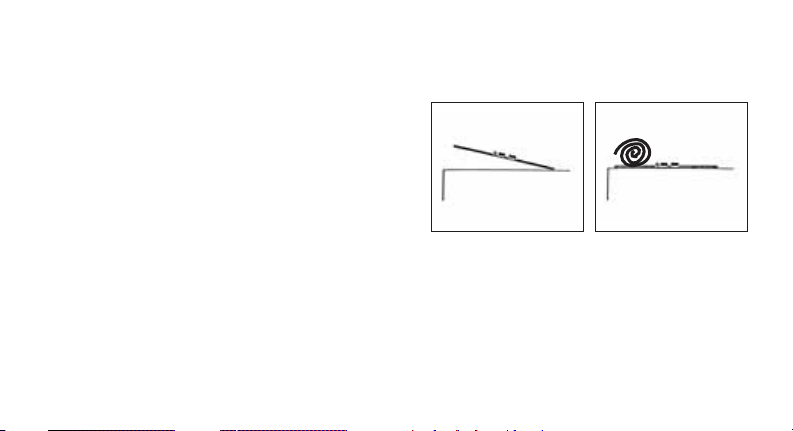
Das C 542 BL ist ein Grenzflächenmikrofon. Die
Mikrofonkapsel ist bündig in eine flache Scheibe eingebaut. Wenn das Mikrofon auf einer akustisch reflektierenden Fläche (Grenzfläche) montiert wird, ist die
Einspracheöffnung auf die Schallquelle gerichtet und
kommt praktisch in einer Ebene mit der akustisch
reflektierenden Fläche zu liegen. Diese Methode verhindert Kammfiltereffekte oder andere Interferenzen,
die sonst auftreten können, wenn Mikrofone in die Nähe
von reflektierenden Oberflächen gebracht werden.
Die Empfindlichkeit und der Frequenzverlauf des
Mikrofons hängt hauptsächlich von der Platzierung
Page 3

der Scheibe ab. Je größer die verwendete Grenzfläche
ist, desto gleichmäßiger wird der resultierende Frequenzverlauf sein und desto tiefer in den Bassbereich
wird das Mikrofon aufnehmen.
Dieses Mikrofon hat eine etwa halbkugelförmige
Richtwirkung, ist also nur vor der verwendeten Grenzfläche empfindlich für Schallereignisse. Dies wird auch
in vielen publizierten Arbeiten und Artikeln über diese
Art von Mikrofonen beschrieben.
Die Empfindlichkeit ist etwa 6 dB höher als die herkömmlicher Kugelmikrofone, wenn das Mikrofon auf
eine große und schallharte Oberfläche (Grenzfläche)
gelegt oder montiert wird. Diese Flächen können Holzoder Steinböden, Wände aus ähnlichem Material,
Decken oder größere Flächen von Instrumenten, z. B.
Klavierdeckel, sein. Die Empfindlichkeitserhöhung
bewirkt auch eine Verbesserung des Geräuschabstandes im gleichen Maße. Das verwendete Kugelmikrofon nach dem Druckempfänger-Prinzip hat
weiters den Vorteil, dass es wesentlich unempfindlicher gegen Trittschall und Windgeräusche ist als
Richtmikrofone.
Die Gummifüßchen, eventuell in Verbindung mit der
beiliegenden Klebemasse, verhindern Reststörungen
von vibrierenden Böden oder Wänden.
Die am Mikrofon einschaltbare Bassabschwächung
hilft zusätzlich, Verzerrungen bei tiefsten Frequenzen
hintanzuhalten, die z.B. durch Rumpel- oder Windgeräusche auftreten können. Die Steilheit des Filters
beträgt ca. 12 dB/Oktave, die Eckfrequenz (-3 dB
Punkt) liegt bei 150 Hz.
Der Mikrofonausgang ist niederohmig und elektronisch symmetriert. Sie können das Mikrofon sowohl
an symmetrische Eingänge mit oder ohne Phantomspeisung als auch an unsymmetrische Eingänge
anschließen. Zum Betrieb des Mikrofons an symmetrischen Eingängen ohne Phantomspeisung oder
unsymmetrischen Eingängen benötigen Sie ein Phantomspeisegerät von AKG, z.B. das B 18.
2 Anschluss
2.1 Allgemeines
Das C 542 BL ist ein Kondensatormikrofon und benötigt daher eine Stromversorgung.
3
Page 4
Das Mikrofon besitzt einen symmetrischen Ausgang
mit 3-poligem XLR-Stecker:
Stift 1 = Masse
Stift 2 = Tonader (inphase)
Stift 3 = Tonader
Sie können das Mikrofon sowohl an symmetrische
Mikrofoneingänge mit oder ohne Phantomspeisung
als auch an asymmetrische Mikrofoneingänge anschließen.
2.2 Eingang mit Phantomspeisung
2.3
C 542 BL
Phantom
C 542 BL
2.2
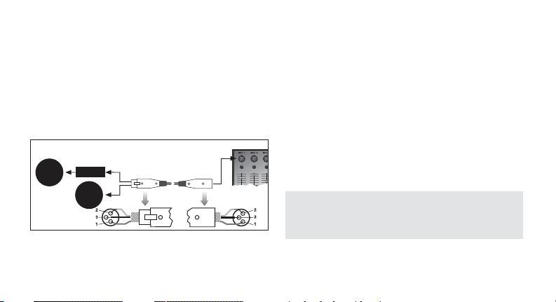
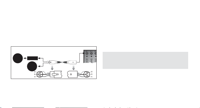
Abb. 1: Anschluss an symmetrischen Eingang
4
Siehe Abb. 1.
1. Schließen Sie das Mikrofon mit einem XLRMikrofonkabel (z.B. dem optionalen MK 9/10 von
AKG) an einen symmetrischen XLR-Mikrofoneingang mit Phantomspeisung an.
2. Schalten Sie die Phantomspeisung ein. (Lesen Sie
dazu in der Betriebsanleitung des jeweiligen Gerätes nach.)
2.3 Eingang ohne Phantomspeisung
Siehe Abb. 1.
• Wenn Ihr Mischpult keine Phantomspeisung besitzt, schalten Sie zwischen Mikrofon und Mischpulteingang ein AKG-Phantomspeisegerät (B 18 optional).
Wichtig!
Wenn Sie andere als die von AKG empfohlenen
Speisegeräte verwenden, kann das Mikrofon
beschädigt werden und erlischt die Garantie.
Page 5
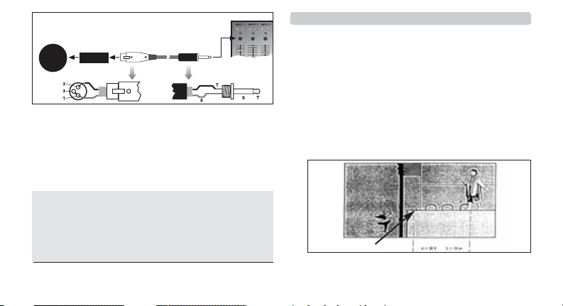
2.4 Asymmetrischer Eingang
Die Phantomspeisegeräte von AKG können Sie auch
an einen asymmetrischen Eingang anschließen.
Verwenden Sie dazu ein Kabel mit XLR-Stecker (weiblich) und Mono-Klinkenstecker:
C 900
Phantom
C 542 BL
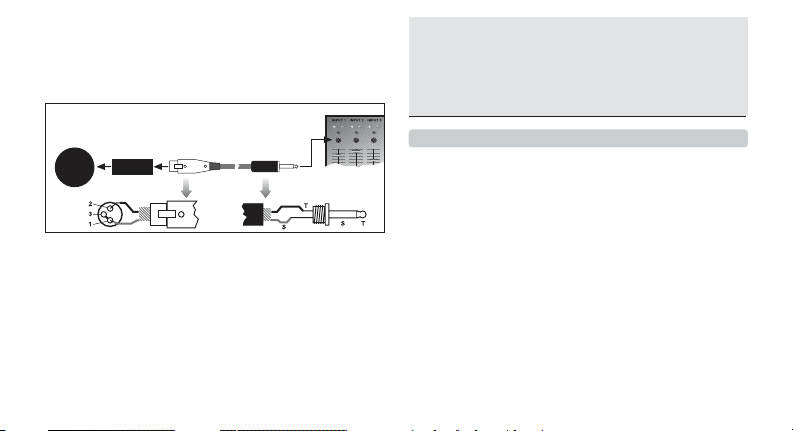
Abb. 2: Anschluss an asymmetrischen Eingang
1. Siehe Abb. 2. Verbinden Sie im XLR-Stecker
mittels einer Drahtbrücke Stift 1 mit Stift 3 und mit
der Abschirmung.
2. Verbinden Sie die innere Ader des Kabels mit Stift
2 des XLR-Steckers und der Spitze des Klinkensteckers.
Hinweis:
Beachten Sie, dass asymmetrische Kabel Einstreuungen aus Magnetfeldern (von Netz- und Lichtkabeln,
Elektromotoren usw.) wie eine Antenne aufnehmen
können. Bei Kabeln von mehr als 5 m Länge kann dies
zu Brumm- und ähnlichen Störgeräuschen führen.
3 Anwendung
3.1 Einleitung
Grenzflächenmikrofone sind unauffällig und einfach zu
platzieren. Deshalb eignet sich das C 542 BL besonders für die Arbeit mit "mikrofonscheuen" Menschen
und Anwendungen, wo aus optisch/ästhetischen
Gründen kein Mikrofon sichtbar sein darf.
Beachten Sie bitte die folgenden Hinweise, um Ihr
Mikrofon optimal einsetzen zu können:
3.2 Allgemeine Aufnahmesituationen
• Siehe Abb. 3. Die einfachste Methode ist, das
Mikrofon etwa 2 bis 10 m vom Aufnahmeobjekt
entfernt auf den Boden zu legen. Die tatsächliche
Entfernung hängt von der physischen Ausdehnung
5
Page 6
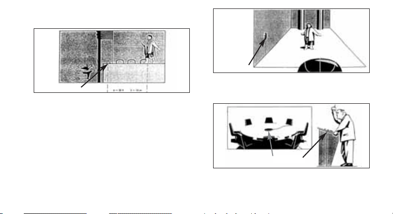
der aufzunehmenden Schallquelle(n) und der spezifischen Situation am Aufnahmeort ab.
C 542 BL
Abb. 3: Einfachste Aufnahmemethode
• Siehe Abb. 4. Sie können auch eine in der Nähe
des Aufnahmeobjekts befindliche schallharte
Wand (keine Tapeten oder Dämmplatten) als
Grenzfläche benutzen. Diese Wand sollte möglichst eben und schallreflektierend sein. Die Mikrofonplatte hat drei Löcher für die Montage an der
Wand oder Decke. Zur besseren Körperschalldämpfung empfehlen wir, die Gummifüßchen in
den Löchern zu belassen.
6
C 542 BL
Abb. 4: Mikrofon an einer Grenzfläche montieren
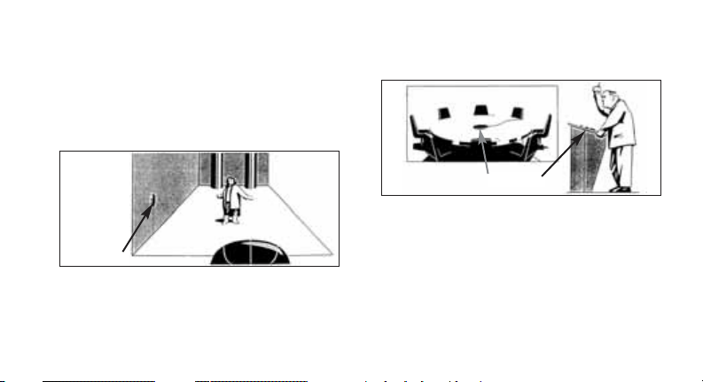
3.3 Konferenztisch / Kirchenkanzel
C 542 BL
Abb. 5: Platzierung des Mikrofons auf Tischen
Page 7
• Siehe Abb. 5. Sie können das Mikrofon auch auf
Konferenztischen oder Kirchenkanzeln völlig
unauffällig einsetzen.
3.4 Montage an Instrumenten
Da das Mikrofon sehr klein und leicht ist, können Sie
es auch direkt an Instrumenten mit ausreichend großer
Grenzfläche, z. B. am Deckel von Klavieren, Pianinos,
Cembalos oder Spinetten montieren.
Verwenden Sie dazu die mitgelieferte Klebemasse.
Diese lässt sich rückstandsfrei entfernen, eine Beschädigung alter oder empfindlicher Lackschichten
kann jedoch nicht ganz ausgeschlossen werden.
3.5 Richtwirkung
Die halbkugelförmige Richtcharakteristik kann zu
ungewollten Aufnahmen aus zuerst nicht berücksichtigten Richtungen führen.
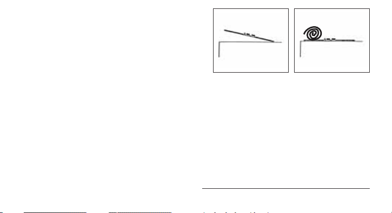
Um solche Störgeräusche auszublenden, können Sie
z.B.
• das Mikrofon mittig auf eine Plexiglasplatte von ca.
1 x 1 m Größe montieren und die Plexiglasplatte
auf die gewünschte Schallquelle ausrichten (s.
Abb. 6), oder
• mit dickem Teppichmaterial zwischen Mikrofon
und störender Schallquelle den Störschall dämpfen (s. Abb. 7).
Abb. 6: Mikrofon auf
Plexiglasplatte montiert
3.6 Tiefenabsenkung
Tieffrequente Rumpel- oder Windgeräusche von normalerweise nicht als störend wahrgenommenen
Quellen wie Klimaanlagen, Verkehrslärm, Gebäude-
Abb. 7: Dickes
Teppichmaterial als
Schallabsorber
7
Page 8
geräusche, etc. kommen bei einer Aufnahme sehr
deutlich zum Vorschein und können deshalb sehr störend wirken. Das im Phantomspeiseadapter eingebaute schaltbare Tiefenfilter bei 150 Hz erlaubt Ihnen,
diese "akustische Störquellen" auszublenden, ohne
den Klangcharakter des/der aufzunehmenden Instruments/Stimme zu verändern. Die Steilheit des Tiefenfilters beträgt 12 dB/Oktave (ca. 1:4) nach unten.
4 Reinigungshinweise
Alle Metalloberflächen können Sie problemlos mit
(Industrie-) Spiritus oder Alkohol reinigen.
5 Technische Daten
Richtcharakteristik: halbkugelförmig
Übertragungsbereich: 20 – 20.000 Hz (auf sehr großer Grenzfläche)
Empfindlichkeit: 20 mV/Pa / - 34 dBV bez. auf 1V/Pa
Elektr. Impedanz: < 600 Ohm
Empfohlene Lastimpedanz: > 2000 Ohm
Grenzschalldruck für 1% Klirrfaktor: 63 Pa / 130 dB SPL
Ersatzgeräuschpegel nach CCIR 468-2: 28 dB
Äquivalentschalldruckpegel nach IEC 60268-4 (A-bew.): 16 dB-A
Dynamikbereich: 114 dB max. (A-bew.)
Tiefenabsenkung: schaltbar auf linear und 150 Hz, 12 dB/Oktave
8
Page 9

Speisespannung: 9 – 52 Volt Universalphantomspeisung
nach DIN 45 596 / IEC 268-15
Strombedarf: < 2 mA
Betriebstemperatur: -20°C bis +60°C
Relative Luftfeuchtigkeit: 99% (+20°C), 95% (+60°C)
Stecker: 3 pol. XLR-Stecker
Gehäuseoberfläche: dunkelgrau
Abmessungen: 80 mm ø x 5 (10) mm
Gewicht (netto): 56 g (ohne Kabel)
Dieses Produkt entspricht den in der Konformitätserklärung angeführten Normen. Sie können die Konformitätserklärung auf http://www.akg.com oder per e-mail an sales@akg.com anfordern.
9
Page 10

1 Precaution/Description
1.1 Precaution
Please make sure that the piece of equipment your
microphone will be connected to fulfills the safety regulations in force in your country and is fitted with a
ground lead.
1.2 Unpacking
• C 542 BL
• Connecting cable w/phantom power adapter
• Adhesive compound
Check that the packaging contains all of the items list-
ed above. Should any item be missing, please contact
your AKG dealer.
1.3 Optional Accessories
• MK 9/10
•B 18
1.4 Features
• Rugged construction
• Low self-noise
10
• Low current consumption
• High reliability
• Transformerless output
• Operates on any phantom power source to
DIN 45 596 / IEC 268-15
• Built-in switchable, 150 Hz, 12 dB/octave bass
cut filter
1.5 Brief Description
The C 542 BL is a boundary microphone. The transducer element is flush mounted in a thin disk. If you
mount the microphone on an acoustically reflective
boundary (wall, floor, ceiling), the sound entry will be
positioned almost in the same plane as the acoustically reflective surface and will point toward the sound
source. This method prevents comb filter effects and
other interference that would normally cause problems
in microphones placed near reflective surfaces.
The sensitivity and frequency response of the microphone depends on the disk position. The larger the
boundary, the smoother the resulting frequency re-
Page 11

sponse and the more extended the microphone's bass
response.
The C 542 BL is an omnidirectional microphone that
will pick up sounds originating in front of the boundary
only. This has been described in many papers and articles about boundary microphones published over the
years.
When you place the microphone on a large acoustically reflective surface (boundary), its sensitivity will be
about 6 dB higher than that of conventional omnidirectional microphones. Such boundaries include wood
or stone floors, walls of similar materials, ceilings, or
large flat surfaces of certain instruments, e.g., piano
lids. This 6-dB increase in sensitivity also improves the
signal/noise ratio by the same amount. In addition, the
omnidirectional transducer (pressure microphone)
used in the C 542 BL is much less sensitive to footfall
and wind noise than unidirectional microphones are.
The rubber feet and supplied adhesive compound that
you may use to mount the microphone minimize residual noise from vibrating floors or walls.
The switchable bass cut filter in the phantom power
adapter further reduces low-end distortion caused by
footfall or wind noise, etc. The filter slope is approx.
12 dB/octave and its corner frequency (3-dB down
point) 150 Hz.
The microphone provides a low-impedance, electronically balanced output. You can connect the microphone both to balanced inputs with or without phantom power and to unbalanced inputs. To use the
microphone with a balanced input with no phantom
power or an unbalanced input you will need an AKG
phantom power supply, e.g., the B 18.
2 Interfacing
2.1 General
The C 542 BL is a condenser microphone and therefore needs a power supply.
11
Page 12
The microphone provides a balanced output on a 3pin male XLR connector:
Pin 1: ground
Pin 2: hot
Pin 3: return
You can connect the microphone either to a balanced
microphone input with or without phantom power or
an unbalanced microphone input.
2.2 Input with Phantom Power
2.3
C 542 BL
Phantom
C 542 BL
2.2
Fig. 1: Connecting to a balanced input.
Refer to fig. 1.
1. Use an XLR cable (e.g., the optional MK 9/10 from
12
AKG) to connect the microphone to a balanced
XLR input with phantom power.
2. Switch the phantom power on. (Refer to the
instruction manual of the unit to which you connected your microphone.)
2.3 Input with No Phantom Power
Refer to fig. 1.
• If your mixer provides no phantom power, connect
an optional AKG phantom power supply (B 18)
between the microphone and the mixer.
Important!
Using any power supply other than those recommended by AKG may damage your microphone
and will void the warranty.
2.4 Unbalanced Input
You may connect AKG phantom power supplies to
unbalanced inputs, too.
Use a cable with a female XLR connector and TS jack
plug:
Page 13
Phantom
C 542 BL
Fig. 2: Connecting to an unbalanced input.
1. Refer to fig. 2. On the XLR connector, use a wire
bridge to connect pin 1 to pin 3 and the cable
shield.
2. Connect the inside wire of the cable to pin 2 on the
XLR connector and the tip contact of the jack plug.
Note:
Unbalanced cables may pick up interference from
stray magnetic fields near power or lighting cables,
electric motors, etc. like an antenna. This may introduce hum or similar noise when you use a cable that
is longer than 16 feet (5 m).
3 Using the Microphone
3.1 Introduction
Boundary microphones are inconspicuous and easy to
position. Therefore, the C 542 BL is an excellent
choice for working with people who tend to shy away
from microphones and applications where no microphone must be visible for visual or esthetic reasons.
The following sections contain hints on how to get the
best possible results.
3.2 General Recording
C 542 BL
Fig. 3: Easy recording technique.
13
Page 14
• Refer to fig. 3. The easiest technique is to place
the microphone on the floor about 7 to 35 feet (2
to 10 m) away from the sound source. The ultimate
working distance will depend on the physical
dimensions of the sound source(s) to be recorded
and the specific situation at the recording location.
• Refer to fig. 4. Alternatively, you may use an acoustically reflective wall (covered with no wallpaper or softboard) near the sound source.
C 542 BL
Fig. 4: Mounting the microphone on a boundary.
The wall should be as even and reflective as pos-
sible. The microphone disk has three holes for
mounting on a wall or ceiling. To ensure optimum
14
deadening of structure-borne noise, we recommend leaving the rubber feet inside the holes.
3.3 Conference Table / Pulpit
C 542 BL
Fig. 5: Placing the microphone on a table.
• Refer to fig. 5. The microphone will keep a very low
profile on conference tables or pulpits, too.
3.4 Mounting the Microphone on an Instrument
Since the microphone is very small and light, you can
even mount it directly on instruments with a sufficiently large boundary such as the lid of a grand or upright
piano, harpsichord, or spinet.
Page 15
Use the supplied adhesive compound. Although it will
leave no residues when removed from most surfaces,
there may be a minimal risk of old or delicate lacquer
coats being damaged.
3.5 Directivity
The microphone's omnidirectional (hemispherical) polar pattern may cause unwanted sounds to be picked
up from unexpected directions.
To suppress these unwanted sounds, you may, for
instance,
• mount the microphone in the center of a plexiglass
panel about 3 feet square and align the plexiglass
panel with the desired sound source (see fig. 6), or
• place thick carpet between the microphone and
the unwanted sound source(s) as shown in fig. 7 to
reduce the spillover.
Fig. 6: Microphone
mounted on plexiglass
panel.
3.6 Bass Cut Filter
Low-frequency rumble or wind noise from sound
sources we do not normally perceive as irritating, such
as air conditioning, traffic, or structure-borne noise,
may become clearly audible and therefore definitely
irritating on a recording. The 150 Hz bass cut filter integrated in the phantom power adapter allows you to
reject this unwanted noise without changing the sound
of the instrument or voice you are recording. The filter
slope is 12 dB/octave (approx. 1:4).
Fig. 7: Using thick carpet to reduce spillover.
15
Page 16

4 Cleaning
You can clean all metal surfaces with (industrial grade)
methylated spirits or alcohol.
5 Specifications
Polar pattern: omnidirectional (hemispherical)
Frequency range: 20 to 20,000 Hz (mounted on very large boundary)
Sensitivity: 20 mV/Pa / -34 dBV re 1 V/Pa
Electrical impedance: < 600 ohms
Recommended load impedance: > 2000 ohms
Max. SPL for 1% THD: 63 Pa / 130 dB SPL
Equivalent noise level to CCIR 468-2: 28 dB
Equivalent noise level to IEC 60268-4 (A-weighted): 16 dB-A
Dynamic range: 114 dB max. (A-weighted)
Bass cut filter: switchable to flat or 150 Hz, 12 dB/octave
Powering: 9 to 52 V phantom power to DIN 45 596/IEC 268-15
Current consumption: < 2 mA
Opeating temperature: -20°C to +60°C
Relative humidity: 99% (+20°C); 95% (+60°C)
16
Page 17

Connector: 3-pin XLR
Finish: dark gray
Dimensions: 80 dia. x 5 (10) mm / 3.1 dia. x 0.2 (0.4) in.
Net weight: 56 g / 2 oz. (without cable)
This product conforms to the standards listed in the Declaration of Conformity. To order a free copy of the
Declaration of Conformity, visit http://www.akg.com or contact sales@akg.com
17
Page 18

1 Consigne de Sécurité/Description
1.1 Consigne de sécurité
Vérifiez si l’appareil auquel vous voulez raccorder le
microphone répond aux prescriptions relatives à la
sécurité en vigueur et s’il possède une mise à la terre
de sécurité.
1.2 Fournitures d'origine
• C 542 BL
• Câble de raccordement / Adaptateur pour alimentation fantôme
• Mastic
Assurez-vous que l’emballage contient bien toutes les
pièces indiquées ci-dessus. Si ce n’est pas le cas,
contactez immédiatement votre fournisseur AKG.
1.3 Accessoires optionnels
• MK 9/10
•B 18
1.4 Caractéristiques particulières
• Mécanisme robuste
• Bruit propre minime
18
• Faible consommation
• Grande sécurité de fonctionnement
• Etage de sortie sans trafo
• Possibilité d’utiliser toute alimentation en fantôme
selon DIN 45 596 / CEI 268-15
• Filtre coupe-bas incorporé commutable, intervenant à la fréquence de 150 Hz (12 dB/octave)
1.5 Brève description
Le C 542 BL est un microphone à zone de surface. La
capsule de micro est montée affleurée dans un disque
plat. Lorsque le microphone est placé sur une surface
acoustique réfléchissante, l’ouverture côté sensible
est dirigée sur la source sonore et se trouve pratiquement au même niveau que la surface réfléchissante.
Cette méthode empêche tout effet de "filtre en
peigne" ou autres susceptibles de se produire lorsqu’un micro se trouve à proximité d’une surface réfléchissante.
La sensibilité et la réponse en fréquence du micro
dépendent principalement de l’emplacement du
disque. Plus la surface réfléchissante est grande, plus
Page 19

la réponse en fréquence est régulière et plus importante est l’étendue du grave capté par le micro.
Ce micro a un diagramme directif approximativement
hémisphérique, il n’est donc sensible à ondes sonores
que devant la surface réfléchissante utilisée. Ce phénomène est décrit dans de nombreux articles et
études publiés sur ce type de micro.
La sensibilité du micro est supérieure de 6 dB environ
à celle des micros omnidirectifs classiques lorsque le
micro est posé ou monté sur une surface réfléchissante suffisamment grande et réverbérante. On peut
utiliser comme surface réfléchissante un plancher ou
une dalle de pierre, des murs en matériaux analogues,
un plafond ou une surface suffisamment grande faisant partie d’un instrument de musique, p.ex. un couvercle de piano. L’augmentation de la sensibilité s’accompagne d’une amélioration correspondante du rapport signal sur bruit. Le micro omnidirectif utilisé,
conçu selon le principe du microphone à pression, a
par ailleurs l’avantage d’être beaucoup moins sensible
aux bruits de pas et de vent que les microphones unidirectionnels.
Les pieds de caoutchouc et l’utilisation, le cas
échéant, du mastic fourni évitent les perturbations
résiduelles pouvant être dues à la vibration du sol ou
d’une cloison.
L’atténuation du grave contribue également à éviter
les distorsions à très basse fréquence dues p.ex. au
rumble ou aux bruits de vent. La pente du filtre est
approx. de 12 dB/octave, la fréquence de coupure
(-3 dB) se situe à 150 Hz.
La sortie du micro à basse impédance est équilibrée
électroniquement. Vous pouvez brancher votre micro
aussi bien sur des entrées symétriques avec ou sans
alimentation fantôme que sur des entrées asymétriques. Pour faire fonctionner le micro sur des entrées
symétriques sans alimentation fantôme ou sur des
entrées asymétriques, vous avez besoin d’un module
d’alimentation fantôme AKG, p.ex. le B 18.
2 Raccordement
2.1 Indications générales
Le C 542 BL est un microphone électrostatique ; il a
donc besoin d’une alimentation.
19
Page 20

Le microphone possède une sortie symétrique avec
fiche XLR tripolaire :
broche 1 = masse
broche 2 = point chaud
broche 3 = point froid
Vous pouvez raccorder le microphone à volonté sur
une entrée micro symétrique avec ou sans alimentation fantôme ou bien sur une entrée asymétrique.
2.2 Entrée avec alimentation fantôme
2.3
C 542 BL
Phantom
C 542 BL
2.2
Fig. 1 : connexion sur une entrée symétrique
Voir Fig. 1
1. Connectez le microphone à l’aide d’un câble de
20
micro XLR-XLR (p.ex. l’AKG MK 9/10 optionnel)
sur une entrée de micro symétrique type XLR avec
alimentation fantôme.
2. Mettez l’alimentation fantôme sous tension
(Veuillez vous reporter à la notice de l’équipement
utilisé).
2.3 Entrée sans alimentation fantôme
Voir Fig. 1
• Si votre table de mixage ne possède pas d’alimentation fantôme, insérez une alimentation fantôme
AKG optionnelle (B 18) entre le micro et l’entrée de
la table de mixage.
Important !
L’utilisation d’alimentations autres que celles
recommandées par AKG peut provoquer des
dégâts sur le micro et entraîne la perte de la garantie.
2.4 Entrée asymétrique
Vous pouvez aussi connecter les alimentations fantôme d’AKG sur une entrée asymétrique.
Page 21

Il vous faut un câble avec une fiche XLR femelle et une
fiche à jack mono:
Phantom
C 542 BL
Fig. 2 : Connexion sur une entrée asymétrique
1. Voir Fig. 2. Pontez les contacts 1 et 3 de la fiche
XLR et reliez-les au blindage du câble.
2. Reliez le conducteur interne du câble au contact 2
de la fiche XLR et à la pointe de la fiche à jack.
Remarque:
Les câbles asymétriques peuvent capter comme une
antenne les interférences de champs magnétiques
(câbles lumière ou force, moteurs électriques, etc.). Si
le câble mesure plus de 5 m ce phénomène pourra se
traduire par des ronflements et autres parasites.
3 Utilisation
3.1 Introduction
Les microphones à zone de surface sont discrets et
simples à placer. Le C 542 BL est donc particulièrement indiqué pour les personnes "intimidées par le
micro" et les applications où le micro doit être invisible
pour des raisons optiques ou esthétiques.
Veuillez vous conformer aux recommandations suivantes :
3.2 Situation courante
•
C 542 BL
Fig. 3 : La méthode la plus simple
Voir Fig. 3. La méthode la plus simple consiste à
21
Page 22

poser le micro sur le sol à une distance de 2 à
10 m de la source à capter. La distance effective
dépend de l’étendue physique de la ou des
sources sonores à capter et de la situation spécifique sur le lieu de la prise de son.
•
bien réfléchir le son. La plaque du micro est percée
de trois trous pour le montage sur une cloison ou
au plafond. Pour une meilleure atténuation des
bruits mécaniques nous conseillons de laisser les
pieds de caoutchouc dans les trous.
3.3 Table de conférence/chaire d’église
•
C 542 BL
Fig. 4: Montage du micro sur une surface réfléchissante
Voir Fig. 4. Vous pouvez également utiliser comme
surface réfléchissante une cloison réverbérante
(pas de papiers peints ou de panneaux isolants).
Cette cloison doit être aussi plane que possible et
22
C 542 BL
Fig. 5: Installation du micro sur une table
Voir Fig. 5. Le micro peut être posé sur une table
de conférence ou la chaire d’une église où il passera facilement inaperçu.
Page 23

3.4 Montage sur un instrument de musique
Le micro étant très petit et léger, vous pouvez aussi le
monter directement sur un instrument de musique,
p.ex. sur le couvercle d’un piano droit ou à queue,
d’un clavecin ou d’une épinette.
Utilisez à cet effet le mastic fourni. Il s’enlève sans
laisser de traces ; on ne peut cependant exclure entièrement le risque de détérioration de vernis anciens ou
délicats.
3.5 Réponse polaire
Le diagramme directif hémisphérique peut entraîner la
capture de sons venant de directions autres que celle
prévue.
Pour éliminer ces bruits parasites vous pouvez p.ex. :
• monter le micro bien centré sur une plaque de
plexiglas de 1 x 1 m environ et orienter la plaque
de plexiglas sur la source sonore voulue (voir
Fig. 6), ou
• atténuer les bruits parasites en intercalant un morceau de carpette épaisse entre le micro et la source sonore gênante (voir Fig. 7).
Fig. 6 : Montage du
micro sur une plaque
de plexiglas
3.6 Atténuation du grave
Le rumble ou les bruits de vent à très basses fréquences provenant de sources sonores qui ne sont
normalement pas perçues comme gênantes – p.ex.
climatisation, bruit de la circulation, bruits dans un
immeuble, etc. s’entendent très bien lorsque le son
est repris par le micro et peuvent alors devenir très
gênants. Le filtre coupe-bas incorporé à l'adaptateur
pour alimentation fantôme, qui intervient à 150 Hz,
Fig. 7 : Morceau de
carpette utilisé pour
absorber le son
23
Page 24

vous permet de neutraliser ces "sources de perturbations acoustiques", sans modifier la sonorité de l’instrument ou
de la voix. La pente du filtre coupe-bas est de
12 dB/octave (1:4 env.) vers le bas.
4 Nettoyage
Toutes les surfaces métalliques peuvent être nettoyées sans problèmes à l’aide d’un chiffon imbibé
d’alcool à brûler.
5 Caractéristiques techniques
Directivité : hémisphérique
Réponse en fréquence : 20 – 20.000 Hz
Sensibilité : 20 mV/Pa / - 34 dBV rapp. à 1V/Pa
Impédance électrique : < 600 Ohm
Impédance de charge recommandée : > 2000 Ohm
Niveau maxi. de pression
pour un facteur de distorsion de 1% : 63 Pa / 130 dB SPL
Niveau de bruit équivalent selon CCIR 468-2 : 28 dB
Niveau de bruit équivalent selon IEC 60268-4 (pond. A) : 16 dB-A
Dynamique : 114 dB max. (pond. A)
Atténuation des graves: commutable sur linéaire et 150 Hz, 12 dB/octave
Tension d’alimentation : 9 – 52 volts, alimentation fantôme universelle
24
(sur une très grande surface réfléchissante)
selon DIN 45 596 / CEI 268-15
Page 25

Consommation : < 2 mA
Température se service : -20°C à +60°C
Hygrométrie relative : 99% (+20°C), 95% (+60°C)
Connecteur : connecteur type XLR à 3 points
Finition du boîtier: gris foncé
Dimensions : 80 mm ø x 5 (10) mm
Poids (net): 56 g (sans câble)
Ce produit est conforme aux normes citées dans la Déclaration de Conformité, dont vous pouvez prendre connaissance en consultant le site http://www.akg.com ou en adressant un e-mail à sales@akg.com
25
Page 26

1 Indicazione per la sicurezza / Descrizione
1.1 Indicazione per la sicurezza
Controllate per favore se l’apparecchio che volete collegare al microfono corrisponde alle norme di sicurezza
vigenti e se è dotato di una messa a terra di sicurezza.
1.2 In dotazione
• C 542 BL
• Cavo di collegamento / adattatore per alimentazione phantom
• Adesivo
Controllate per favore se la confezione contiene tutte
le parti sopra indicate. Se manca qualcosa, rivolgetevi al vostro rivenditore AKG.
1.3 Accessori opzionali
• MK 9/10
•B 18
1.4 Caratteristiche particolari
• Meccanica robusta
• Poco rumore proprio
26
• Scarso assorbimento
• Alta sicurezza d’esercizio
• Stadio d’uscita senza trasformatore
• Alimentazione con qualsiasi dispositivo di alimentazione phantom secondo DIN 45 596 / IEC 268-15
• Filtro dei bassi integrato, regolabile, con punto
d’inserzº27
ione del filtro a 150 Hz (12 dB/ottava)
1.5 Breve descrizione
Il C 542 BL è un microfono a superficie di separazione. La capsula microfonica è inserita a raso in un disco
piatto. Se il microfono è montato su una superficie
acusticamente riflettente (superficie di separazione), il
foro di ripresa è orientato sulla fonte acustica e si posiziona praticamente allo stesso livello della superficie
acusticamente riflettente. Questo metodo evita effetti
di filtro a pettine o altre interferenze che altrimenti si
potrebbero verificare quando i microfoni si trovano
nelle vicinanze di superfici riflettenti.
La sensibilità e la risposta in frequenza del microfono
dipendono soprattutto dal posizionamento del disco.
Page 27

Più grande è la superficie di separazione utilizzata, più
regolare sarà la risposta in frequenza e più il microfono riprenderà i registri bassi.
Questo microfono ha una direttività "semisferica" e
perciò è sensibile agli eventi sonori solo davanti alla
superficie di separazione utilizzata. Questo fenomeno
viene descritto anche in molti lavori e articoli pubblicati su questo tipo di microfoni.
La sensibilità è di circa 6 dB più alta di quella dei tradizionali microfoni omnidirezionali se il microfono
viene posto o montato su una superficie grande e acusticamente inerte (superficie di separazione). Queste
superfici possono essere pavimenti in legno o in pietra, pareti di materiale simile, soffitti o superfici più
grandi di strumenti, p.e. coperchi di pianoforti.
L’aumento di sensibilità comporta anche un miglioramento del rapporto segnale/rumore della stessa misura. Il microfono omnidirezionale realizzato secondo il
principio del microfono di pressione presenta inoltre il
vantaggio di essere notevolmente meno sensibile dei
microfoni direzionali per quanto a vibrazioni meccaniche e rumori del vento.
I piedini in gomma, da usare eventualmente insieme
all’adesivo in dotazione, evitano disturbi residui provocati da pavimenti o soffitti vibranti.
L’attenuazione dei bassi regolabile sul microfono aiuta
inoltre a eliminare distorsioni che si verificano nelle frequenze più basse a causa di p.e. rumori prodotti dal
vento. La transconduttanza del filtro è di circa 12 dB/
ottava, la frequenza limite (punto -3 dB) si aggira sui
150 Hz.
L’uscita microfonica è a bassa impedenza ed è elettronicamente simmetrizzata. Potete collegare il microfono sia ad ingressi simmetrici con o senza alimentazione phantom che ad ingressi asimmetrici. Per gestire il microfono collegato ad ingressi simmetrici senza
alimentazione phantom o ad ingressi asimmetrici,
avete bisogno di un apparecchio di alimentazione
phantom della AKG, p.e. il B 18.
2 Collegamento
2.1 Indicazioni generali
Il C 542 BL è un microfono a condensatore e ha quindi bisogno di alimentazione.
27
Page 28

Il microfono è dotato di un’uscita simmetrica con connettore XLR a 3 poli.
Pin 1 = massa
Pin 2 = filo audio (inphase)
Pin 3 = filo audio
Potete collegare il microfono sia ad ingressi microfonici simmetrici con o senza alimentatzione phantom che
a quelli asimmetrici.
2.2. Ingresso con alimentazione phantom
2.3
C 542 BL
Phantom
C 542 BL
2.2
Fig. 1:Collegamento ad un ingresso simmetrico
Vedi fig. 1.
1. Collegate il microfono ad un ingresso microfonico
28
XLR simmetrico con alimentazione phantom servendovi di un cavo microfonico XLR (p.e. l’opzionale MK 9/10 della AKG).
2. Inserite l’alimentazione phantom. (Leggete in merito le istruzioni per l’uso del rispettivo apparecchio.)
2.3 Ingresso senza alimentazione phantom
Vedi fig. 1.
• Se il vostro mixer non è dotato di alimentazione
phantom, interponete tra microfono e ingresso sul
mixer un alimentatore phantom AKG opzionale (B 18).
Importante!
Se usate alimentatori diversi da quelli raccomandati dall’AKG, il microfono può subire danni
e la garanzia si estingue.
2.4 Ingresso asimmetrico
Gli alimentatori phantom dell’AKG possono venir collegato anche ad un ingresso asimmetrico.
Usate un cavo con una presa XLR e una spina jack
mono:
Page 29

Phantom
C 542 BL
Fig. 2: Collegamento ad un ingresso asimmetrico
1. Vedi fig. 2. Nella presa XLR, collegate con un
ponte a filo i contatti 1 e 3 e portateli sullo schermo del cavo.
2. Collegate il conduttore interno del cavo con il contatto 2 della presa XLR e la punta della spina jack.
Nota:
Tenete presente che i cavi asimmetrici possono assorbire, come un’antenna, irradiazioni da campi magnetici
(cavi di rete, cavi della luce, elettromotori ecc.). Nel caso
di cavi la cui lunghezza supera i 5 m, questo fenomeno
può causare ronzìi ed altri rumori disturbanti.
3 Impieghi
3.1 Introduzione
I microfoni a superficie di separazione sono poco
appariscenti e da posizionare senza problemi. Il C 542
BL si presta quindi particolarmente bene per il lavoro
con persone che hanno una "fobia microfonica" e per
impieghi dove per ragioni ottiche/estetiche non si
deve vedere il microfono.
Per poter impiegare il microfono in modo ottimale,
rispettate per favore le seguenti indicazioni:
3.2 Situazioni generali di ripresa
• Vedi fig. 3. Il metodo più semplice è quello di posizionare il microfono sul pavimento, ad una distanza di circa 2 – 10 m dall’oggetto da riprendere.
L’effettiva distanza dipende dall’estensione fisica
della/e fonte/i sonora/e da riprendere e dalla situazione specifica sul luogo di ripresa.
Fig. 3: Metodo di ripresa più semplice
29
Page 30

C 542 BL
• Vedi fig. 4. Come superficie di separazione potete
usare anche una parete acusticamente inerte
(senza carta da parati o pannelli isolanti) vicina
all’oggetto da riprendere. Questa parete dovrebbe
essere il più possibile piana e riflettere il suono. La
piastra del microfono ha tre fori per il montaggio
sulla parete o sul soffitto. Per ammortizzare meglio
le vibrazioni meccaniche, raccomandiamo di
lasciare i piedini in gomma nei fori.
Fig. 4: Come montare il microfono su una superfi-
30
C 542 BL
cie di separazione
3.3 Tavolo da conferenza/Pulpito di chiesa
Fig. 5: Come posizionare il microfono su tavoli
C 542 BL
• Vedi fig. 5. Potete impiegare il microfono anche su
Page 31

tavoli da conferenza o pulpiti di chiesa senza che
dia nell’occhio.
3.4 Montaggio su strumenti
Visto che il microfono è molto piccolo e leggero, potete montarlo anche direttamente su strumenti con una
superficie di separazione sufficientemente grande,
p.e. sul coperchio di pianoforti a coda, pianoforti verticali, cembali o spinette.
Per questo tipo di montaggio usate l’adesivo in dotazione. L’adesivo può essere rimosso senza lasciar
residui, non si possono tuttavia escludere del tutto
danneggiamenti degli strati di vernice molto antichi o
sensibili.
3.5 Direttività
La direttività "semisferica" può causare riprese non
volute da direzioni non tenute in considerazione.
Per eliminare disturbi di questo genere, potete per
esempio:
• montare il microfono nel centro di una piastra in
plexiglas della grandezza di circa 1 x 1 m e orien-
tare la piastra in direzione della fonte sonora prescelta (vedi fig. 6), oppure
• smorzare il rumore con l’aiuto di materiale spesso
per tappeti inserito tra microfono e fonte sonora
disturbante (vedi fig. 7).
Fig. 6: Microfono montato su una piastra in
plexiglas
3.6 Attenuazione dei bassi
Rumori a frequenze basse o rumori causati dal vento,
provenienti da fonti normalmente non percepite come
disturbanti, come impianti di condizionamento dell’a-
Fig. 7: Spesso materiale per tappeti per
assorbire il suono
31
Page 32

ria, rumori del traffico ecc. vengono percepiti molto
chiaramente nella ripresa e possono quindi disturbare
notevolmente. Il filtro dei bassi regolabile a 150 Hz,
incorporato nell’adattatore di alimentazione phantom,
vi permette di eliminare queste "fonti di disturbo acustico" senza alterare il suono dello/degli strumento/
strumenti/della voce da riprendere. La transconduttanza del filtro dei bassi è di 12 dB/ottava (circa 1:4) in
basso.
4 Pulizia
Tutte le superfici metalliche possono venir pulite senza
problemi con spirito (industriale) o alcool.
5 Dati tecnici
Direttività: semisferica
Risposta in frequenza: 20–20.000 Hz (su superficie di separazione molto
Sensibilità: 20 mV/Pa / - 34 dBV rif. a 1V/Pa
Impedenza elettrica: < 600 Ohm
32
grande)
Page 33

Impedenza di carico raccomandata: > 2000 Ohm
Pressione acustica limite
per un fattore di distorsione di 1%: 63 Pa / 130 dB SPL
Livello del rumore equivalente secondo CCIR 468-2: 28 dB
Livello di rumore equivalente
secondo IEC 60268-4 (ponderazione A): 16 dB-A
Gamma dinamica: 114 dB mass. (ponderazione A)
Attenuazione dei bassi: regolabile su "lineare" e su 150 Hz, 12 dB/ottava
Tensione di alimentazione: 9 – 52 Volt alimentazione phantom universale
secondo DIN 45 596 / IEC 268-15
Assorbimento: < 2 mA
Temperatura d’esercizio: da -20°C fino a +60°C
Umidità relativa dell’aria: 99% (+20°C), 95% (+60°C)
Connettore: connettore XLR a 3 poli
Superficie della scatola: grigio scuro
Dimensioni: 80 mm ø x 5 (10) mm
Peso (netto): 56 g (senza cavo)
Questo prodotto corrisponde alle norme elencate nella dichiarazione di conformità, che è disponibile al sito
http://www.akg.com oppure all'indirizzo email sales@akg.com
33
Page 34

1 Indicaciones de seguridad/Descripción
1.1 Indicaciones de seguridad
Sírvase verificar si el aparato al cual quiere conectar el
micrófono cumple con las disposiciones de seguridad
vigentes y está equipado con una toma de tierra de
seguridad.
1.2 Volumen de suministros
• C 542 BL
• Cable de conexión / Adaptador de alimentación
fantasma
• Masa adhesiva
Sírvase controlar que el embalaje contenga todas las
piezas indicadas más arriba. Si llegara a faltar algo,
rogamos dirigirse a su distribuidor AKG.
1.3 Accesorios opcionales
• MK 9/10
•B 18
1.4 Características especiales
• Mecánica resistente
34
• Ruido inherente bajo
• Consumo de corriente bajo
• Elevada fiabilidad operacional
• Etapa de salida sin transformador
• Alimentación con cualquier dispositivo de alimentación fantasma según DIN 45 596 / IEC 268-15
• Filtro de graves integrado y conmutable, con
punto inicial del filtro en 150 Hz (12 dB/octava)
1.5 Descripción breve
El C 542 BL es un micrófono de superficie. La cápsula microfónica está integrada a ras en un disco plano.
Si el micrófono es montado en una superficie reflectante (superficie límite), la rejilla está dirigida hacia la
fuente sonora y está prácticamente al mismo nivel que
la superficie acústica reflectante. Este método evita
efectos de filtro de peine u otras interferencias que
pueden producirse cuando los micrófonos se colocan
cerca de superficies reflectantes.
La sensibilidad y la curva de respuesta del micrófono
dependen esencialmente del emplazamiento del
disco. Cuanto más grande sea la superficie límite
Page 35

tanto más uniforme será la curva de respuesta resultante y tanto más baja será la gama de graves en que
grabará el micrófono.
Este micrófono tiene una característica direccional
casi hemisférica, con lo cual es sensible a eventos
sonoros solamente delante de la superficie límite utilizada. Esto ha sido descrito también en muchos artículos publicados sobre estos micrófonos.
La sensibilidad es unos 6 dB superior a la de los
micrófonos omnidireccionales normales si el micrófono se coloca o se monta en una superficie grande y
reflectante (superficie límite). Estas superficies pueden
ser suelos de madera o de piedra, muros de materiales similares, techos o superficies mayores de instrumentos, como por ejemplo, tapas de pianos. El
aumento de la sensibilidad produce, en la misma
medida, una mejora de la relación señal a ruido. El
micrófono omnidireccional utilizado según el principio
de micrófono a presión, tiene además la ventaja de
que es mucho menos sensible a ruidos de pasos y de
viento que los micrófonos direccionales.
Los pies de caucho, si se les aplica la masa adhesiva
suministrada, impiden perturbaciones residuales provenientes de suelos vibrantes o de muros.
La atenuación de graves, que se puede accionar en el
micrófono, ayuda asimismo a impedir distorsiones en
las frecuencias más bajas que pueden producirse, por
ejemplo, por ronguidos o ruidos de viento. La transconductancia del filtro es de aprox. 12 dB/octava, la frecuencia límite (punto -3 dB) se encuentra en 150 Hz.
La salida del micrófono es de baja impedancia y electrónicamente equilibrada. El micrófono se puede
conectar tanto a entradas balanceadas con alimentación fantasma o sin ella, como también a entradas
desbalanceadas. Para la utilización del micrófono en
entradas balanceadas sin alimentación fantasma o en
entradas desbalanceadas se necesita un dispositivo de
alimentación fantasma de AKG, por ejemplo el B 18.
2 Conexión
2.1 Indicaciones generales
El C 542 BL es un micrófono de condensador y necesita, por lo tanto, alimentación de corriente.
35
Page 36

El micrófono dispone de una salida simétrica con
conector XLR de 3 polos:
Clavija 1 = tierra
Clavija 2 = audio (en fase)
Clavija 3 = audio
El micrófono se puede conectar a entradas de micrófono balanceadas con o sin alimentación fantasma o a
entradas no balanceadas.
2.2 Entrada con alimentación fantasma
2.3
C 542 BL
Phantom
C 542 BL
2.2
Fig. 1: Conexión a una entrada balanceada.
Ver fig. 1.
1. Conecte el micrófono a una entrada de micrófono
36
XLR balanceada con alimentación fantasma utilizando un cable XLR de micrófono (por ej.: el MK
9/10 de AKG, que se suministra como opcional).
2. Concecte la alimentación fantasma (consulte para
ello el Modo de empleo del aparato correspondiente).
2.3 Entrada sin alimentación fantasma
Ver fig. 1.
• Si su pupitre de mezcla no tiene alimentación fantasma, conecte un alimentador fantasma opcional
de AKG (B 18) entre el micrófono y la entrada del
pupitre de mezcla.
¡Importante!
Si se utilizan alimentadores diferentes a los
recomendados por AKG puede dañarse el micrófono, cesando con ello la garantía.
2.4 Entrada no balanceada
Los alimentadores fantasma de AKG pueden conectarse también a una entrada no balanceada.
Page 37

Use un cable con una hembra de conector XLR y un
conector jack mono:
Phantom
C 542 BL
Fig. 2: Conexión a una entrada no balanceada.
1. Ver fig. 2. Una mediante un puente de alambre la
espiga 1 del conector XLR con la espiga 3 y con la
pantalla del cable.
2. Una el conductor interno del cable con la espiga 2
del conector XLR y la punta del conector jack.
Nota:
Los cables no balanceados pueden recoger interferencias de campos magnéticos (de los cables de red,
de alumbrado, de motores eléctricos, etc.) igual que
una antena. En los cables de más de 5 m de largo,
esto puede producir ruidos de zumbido u otras perturbaciones.
3 Utilización
3.1 Introducción
Los micrófonos de superficie pueden emplazarse en
forma discreta y sencilla. Por eso, el C 542 BL es muy
apropiado para ser utilizado con personas recelosas a
los micrófonos y en aplicaciones en que, por motivos
ópticos o estéticos, no debe verse el micrófono.
Para poder utilizar su micrófono en forma óptima, sírvase seguir las indicaciones que siguen:
3.2 Grabaciones normales
• Véase la Fig. 3. El método más sencillo es colocar
el micrófono en el suelo a unos 2 a 10 m del objeto a grabar. La distancia exacta depende de la extensión física de la(s) fuente(s) sonora(s) a grabar y
de la situación específica en el lugar de grabación.
37
Page 38

C 542 BL
Fig. 3: El método de grabación más sencillo
• Véase la Fig. 4. Como superficie límite se puede
utilizar también un muro reflectante (pero no papel
mural o placas termoaislantes) cerca del objeto a
grabar. Este muro debe ser liso y reflectante de sonidos. El disco del micrófono tiene tres agujeros
para el montaje en muros o techos. Para obtener
una mejor atenuación de ruidos mecánicos recomendamos dejar los pies de caucho en los agujeros.
38
C 542 BL
Fig. 4: Montaje del micrófono en una superficie
límite.
3.3 Mesas de conferencia/Púlpitos en iglesias
C 542 BL
Fig. 5: Emplazamiento del micrófono en mesas.
Page 39

• Véase la Fig. 5. El micrófono se puede montar
también, en forma muy discreta, en mesas de conferencia o en púlpitos de iglesia.
3.4 Montaje en instrumentos
Puesto que el micrófono es muy pequeño y liviano, se
lo puede montar también directamente en instrumentos con una superficie límite bastante grande, como
por ejemplo en la tapa de pianos, pianinos, cémbalos
o clavicordios.
Utilice para ello la masa adhesiva suministrada. Esta
se puede quitar sin dejar residuos, aunque no se
puede excluir totalmente el que se dañen capas de
barniz antiguas o sensibles.
3.5 Efecto direccional
La característica direccional hemisférica puede producir grabaciones involuntarias de direcciones no tenidas en cuenta originalmente.
Para suprimir esos ruidos parásitos usted puede, por
ejemplo:
• montar el micrófono en el centro de una plancha
de plexiglas de aprox. 1 x 1 m y orientarla hacia la
fuente sonora deseada (véase Fig. 6), o bien
• atenuar el ruido perturbador con material de
alfombras entre el micrófono y la fuente sonora
parásita (véase Fig.7).
Fig. 6: Montaje del
micrófono en una plancha de plexiglas.
3.6 Atenuación de graves
Ronguidos o ruidos de viento de baja frecuencia, provenientes de fuentes que normalmente no se consideran como perturbantes, como ser aparatos de climati-
Fig. 7: Material de
alfombras como absorbente de ruido.
39
Page 40

zación, ruido de tráfico, ruidos de edificios etc. se
manifiestan muy nítidamente en una grabación, pudiendo tener un efecto muy perturbador. En 150 Hz, el
filtro de graves conmutable, integrado en el adaptador
de alimentación fantasma, le permite suprimir estas
"fuentes acústicas perturbadoras" sin alterar el carácter sonoro del instrumento o la voz que se estén grabando. La transductancia del filtro de atenuación de
graves es de 12 dB/octava (aprox. 1:4) hacia abajo.
4 Limpieza
Todas las superficies metálicas se pueden limpiar sin
problema con alcohol industrial o alcohol etílico.
5 Datos técnicos
Característica direccional: hemisférica
Gama de transmisión: 20 – 20.000 Hz (en superficie límite muy grande)
Sensibilidad: 20 mV/Pa / - 34 dBV rel. a 1V/Pa
Impedancia eléctrica: < 600 ohmios
Impedancia de carga recomendada: > 2000 ohmios
Presión sonora máx.
para un factor de distorsión no lineal de 1%: 63 Pa / 130 dB SPL
Nivel sonoro según CCIR 468-2: 28 dB
Nivel de ruido equivalente según IEC 60268-4 (pond. A): 16 dB-A
Gama dinámica: 114 dB máx. (pond. A)
40
Page 41

Atenuación de graves: conmutable a lineal y 150 Hz, 12 dB/octava
Tensión de alimentación: 9 – 52 V alimentación fantasma universal
según DIN 45 596 / IEC 268-15
Consumo de corriente: < 2 mA
Temperatura de régimen: -20°C hasta +60°C
Humedad relativa del aire: 99% (+20°C), 95% (+60°C)
Conector: conector XLR de 3 polos
Superficie de la caja: gris oscuro
Dimensiones: 80 mm Ø x 5 (10) mm
Peso (neto): 56 g (sin cable)
Este aparato corresponde a las normas citadas en la declaración de conformidad. Esta última está disponible
en el sitio http://www.akg.com o puede ser solicitada al correo electrónico sales@akg.com
41
Page 42

1 Aviso de segurança/Apresentação
1.1 Aviso de segurança
Certifique-se de que o aparelho ao qual pretende ligar
o microfone está ligado à terra e que corresponde às
normas de segurança.
1.2 Conteúdo da embalagem
• C 542 BL
• Cabo de conexão / adaptador de alimentação fantasma
• Massa adesiva
Verifique se a embalagem contém todos os componentes acima indicados. Caso falte algo, favor entre
em contato com a concessionária da AKG.
1.3 Acessórios opcionais
• MK 9/10
•B 18
1.4 Características especiais
• Mecânica robusta
• Pouco ruído interno
42
• Baixo consumo de energia
• Alta segurança de operação
• Etapa de saída sem transformador
• Alimentação através de todo tipo de aparelho
de alimentação fantasma segundo DIN 45 596 /
IEC 268-15
• Filtro de graves regulável com ponto de início em
150 Hz (12 dB/oitava)
1.5 Apresentação em breve
O C 542 BL é um microfone de superfície. A cápsula
está embutida em linha num disco plano. Se o microfone ficar fixado numa superfície que reflita os sons
acústicos (superfície de limite), a abertura de entrada
de som está direcionada para a fonte sonora, encontrando-se a um mesmo nível com a superfície refletora. Este método impede efeitos "filtro de pente" ou outras interferências que poderiam ocorrer quando microfones se encontram perto de superfícies refletoras.
A sensibilidade e a resposta de freqüência dependem
sobretudo do posicionamento do disco. Quanto maior
for a superfície de limite, tanto mais uniforme será a
Page 43

resposta de freqüência resultante e tanto mais o
microfone captará na faixa dos graves.
Este microfone possui uma característica omnidirecional, isto é, captará todas as fontes sonoras presentes
diante da superfície de limite. Este efeito é descrito
também em várias publicações e artigos sobre este
tipo de microfone.
A sensibilidade é ca. 6 dB maior do que a de microfones omnidirecionais comuns, se o microfone for posicionado ou fixado em uma superfície grande e refletora (superfície de limite). Estas superfícies podem ser
pisos de madeira ou de pedra, paredes de material
análogo, tetos ou grandes superfícies de instrumentos, como por exemplo, a tampa de um piano. O
aumento da sensibilidade melhora também a relação
sinal/ruído. O transdutor omni-direcional que trabalha
conforme o princípio de microfone de pressão possui,
além disso, a vantagem de ficar mais insensível em
relação a ruídos de passos ou de vento do que os
microfones direcionais.
Os pequenos pés de borracha, eventualmente em
combinação com a massa adesiva incluída na emba-
lagem, impedem ruídos restantes de solos ou paredes
vibrantes.
Ainda mais, a atenuação de graves regulável no
microfone ajuda a deter distorções em freqüências
baixíssimas que poderão ocorrer em virtude de ruídos
surdos ou ruídos de vento. A inclinação do filtro é de
ca. 12 dB/oitava e a freqüência de corte (ponto -3 dB)
encontra-se a 150 Hz.
A saída do microfone possui baixa impedância e está
balanceada eletronicamente. Pode ligar o microfone a
entradas balanceadas com ou sem alimentação fantasma e também a entradas não balanceadas. Para
operar o microfone em entradas balanceadas sem alimentação fantasma ou em entradas não balanceadas
necessita de um aparelho de alimentação fantasma
da AKG, como por exemplo, o B 18.
2 Conexão
2.1 Indicações gerais
O C 542 BL é um microfone de condensador e por
isso precisa de uma alimentação de corrente.
43
Page 44

O microfone possui uma saída balanceada com um
plugue XLR com 3 pólos:
Pino 1 = massa
Pino 2 = áudio (em fase)
Pino 3 = áudio
Pode ligar o microfone a entradas de microfone balanceadas com ou sem alimentação fastasma assim
como entradas não balanceadas.
2.2 Entrada com alimentação fantasma
2.3
C 542 BL
Phantom
C 542 BL
2.2
Fig. 1: Conexão a uma entrada balanceada.
Veja fig. 1.
1. Ligue o microfone com um cabo XLR (por exemplo
44
o MK 9/10 opcional da AKG) a uma entrada de
microfone XLR balanceada com alimentação fantasma.
2. Ligue a alimentação fantasma. (Veja as instruções
de uso do equipamento ao qual o microfone está
ligado.)
2.3 Entrada sem alimentação fantasma
Veja fig. 1.
• Se sua mesa de mistura não tiver uma alimentação
fantasma, conete um alimentador fantasma opcional da AKG (B 18) entre o microfone e a entrada na
mesa de mistura.
Importante!
Se usar outros alimentadores senão aqueles
recomendados pela AKG, o microfone pode ser
danado e caduca a garantia.
2.4 Entrada não balanceada
Pode conetar os alimentador fantasma da AKG a uma
entrada ou balanceada ou não balanceada.
Page 45

Use um cabo com um conector XLR fêmea e um plugue jaque mono:
Phantom
C 542 BL
Fig. 2: Conexão a uma entrada não balanceada
1. Solde em ponte os pinos 1 e 3 no conetor XLR e
conete à blindagem do cabo.
2. Conete o condutor interno do cabo com o pino 2
do conetor XLR e com a ponta do plugue jaque.
Nota:
Os cabos não balanceados podem absorver radiações de campos magnéticos (cabos de rede, cabos de
iluminação, motores elétricos, etc.) como uma antena.
Em cabos com mais de 5 m de comprimento isto
poderá levar a zumbidos e outros ruídos.
3 Operação
3.1 Introdução
Microfones de superfície são discretos e podem ser
posicionados com facilidade. Por isso o C 542 BL é
especialmente adequado para o trabalho com pessoas que "ficam intimidados por microfones" e aplicações em que não é desejável que se veja um microfone
por razões de estética.
Por favor, observe os seguintes avisos para poder
aplicar o microfone da melhor forma possível:
3.2 Situações de gravação geral
• Veja fig. 3. O método mais fácil é posicionar o microfone no chão a uma distância de ca. 2 a 10 m
do objeto de gravação. A distância real depende
da extensão física da(s) fonte(s) sonora(s) a serem
gravadas e da situação específica no lugar de gravação.
45
Page 46

C 542 BL
Fig. 3: método mais simples de gravação
• Veja fig. 4. Pode usar também uma parede refletora (sem papel de parede ou placa isoladora) como
C 542 BL
Fig. 4: Fixar o microfone numa superfície de limite
46
superfície de limite. Esta parede deverá ser plana
e refletir o som. A placa do microfone tem três aberturas para a montagem na parede ou no teto. Para
atenuar melhor os ruídos vibracionais, recomendamos deixar os pequenos pés nas aberturas.
3.3 Mesa de conferência/púlpito de igreja
• Veja fig. 5. Pode aplicar o microfone, de maneira
quase imperceptível, também em mesas de conferência e em púlpitos de igreja.
C 542 BL
Fig. 5: Posicionar o microfone em mesas
Page 47

3.4 Montagem em instrumentos
Visto que o microfone é muito pequeno e leve, pode
fixá-lo também em instrumentos com superfície de
limite com tamanho suficiente, como por exemplo na
tampa de pianos de cauda, pianos verticais, cravos ou
espinetas.
Para tanto use a massa adesiva incluída na embalagem. Esta pode ser removida sem deixar vestígios,
mas não se pode excluir que prejudique camadas de
esmalte antigas ou sensíveis.
3.5 Como atenuar fontes sonoras indesejadas
A característica semi-esférica poderá levar a gravações indesejadas provenientes de direções que anteriormente não foram consideradas.
Para evitar tais ruídos pode
• fixar o microfone numa placa de vidro plexi no
tamanho de ca. 1 x 1 m e direcionar a placa de
vidro plexi para a fonte sonora desejada (veja
fig. 6), ou
• atenuar o ruído com tecido de tapete espesso,
posicionando o mesmo entre o microfone e a fonte
do ruído perturbador (veja fig. 7).
Fig. 6: microfone fixado
numa placa de vidro
plexi
3.6 Atenuação dos graves
Ruídos surdos ou ruídos de vento a freqüências baixas provenientes de fontes sonoras que normalmente
não são percebidos de maneira que incomodem,
como por exemplo, aparelhos de ar condicionado, ruídos de trânsito, ruídos de prédios, etc. destacam-se
Fig. 7: material de
tapete espesso para
atenuar ruídos
47
Page 48

notavelmente durante uma gravação e podem incomodar. O filtro de graves a 150 Hz integrado no adaptador de alimentação fantasma permite cortar "fontes
sonoras perturbadoras", sem alterar o caráter do instrumento/da voz a ser gravada. A inclinação do filtro é
de 12 dB/oitava (ca. 1:4) abaixo.
4 Limpeza
Pode limpar todas as superfícies de metal com álcool
etílico (industrial) ou álcool normal.
5 Especificações
Característica direcional: omnidirecional (hemisférica)
Banda passante: 20 – 20.000 Hz
Sensibilidade: 20 mV/Pa = - 34 dBV em rel. a 1V/Pa
Impedância elétrica: < 600 ohms
Impedância de carga recomendada: > 2000 ohms
Pressão sonora limite para 1% de distorção: 63 Pa = 130 dB SPL
Nível de ruído equivalente conforme CCIR 468-2: 28 dB
Nível de ruído equivalente
conforme IEC 60268-4 (pond. A): 16 dB-A
Faixa dinâmica: 114 dB max. (pond. A)
Atenuação de graves: regulável para linear e 150 Hz, 12 dB/oitava
48
(numa superfície de limite muito grande)
Page 49

Tensão de alimentação: 9 – 52 V, alimentação fantasma universal
conforme DIN 45 596 / IEC 268-15
Consumo de energia: < 2 mA
Temperatura de operação: -20°C até +60°C
Umidade relativa do ar: 99% (+20°C), 95% (+60°C)
Conetor: XLR de 3 pólos
Cor da superfície da carcaça: cinza escura
Dimensões: 80 mm ø x 5 (10) mm
Peso (neto): 56 g (sem cabo)
Este produto corresponde às normas citadas na declaração de conformidade, que pode pedir na nossa página da web http://www.akg.com, ou enviando-nos um email para sales@akg.com
495051
Page 50

Page 51

Page 52

Mikrofone · Kopfhörer · Drahtlosmikrofone · Drahtloskopfhörer · Kopfsprechgarnituren · Akustische Komponenten
Microphones · Headphones · Wireless Microphones · Wireless Headphones · Headsets · Electroacoustical Components
Microphones · Casques HiFi · Microphones sans fil · Casques sans fil · Micros-casques · Composants acoustiques
Microfoni · Cuffie HiFi · Microfoni senza filo · Cuffie senza filo · Cuffie-microfono · Componenti acustici
Micrófonos · Auriculares · Micrófonos inalámbricos · Auriculares inalámbricos · Auriculares con micrófono · Componentes acústicos
Microfones · Fones de ouvido · Microfones s/fios · Fones de ouvido s/fios · Microfones de cabeça · Componentes acústicos
Technische Änderungen vorbehalten. Specifications subject to change without notice. Ces caractéristiques sont susceptibles de modifications.
Ci riserviamo il diritto di effettuare modifiche tecniche. Nos reservamos el derecho de introducir modificaciones técnicas. Especificações sujeitas à mudanças sem aviso prévio.
AKG Acoustics GmbH
Lemböckgasse 21–25, P.O.B. 158, A-1230 Vienna/AUSTRIA, Tel: (+43 1) 86 654-0*, Fax: (+43 1) 86 654-7516,
www.akg.com, e-mail: sales@akg.com, Hotline: (+43 676) 83200 888, hotline@akg.com
AKG Acoustics GmbH
Bodenseestraße 228, D-81243 München/GERMANY, Tel: (+49 89) 87 16-0, Fax: (+49 89) 87 16-200,
www.akg.com/de, e-mail: infode@akg.com, Hotline: (+49 89) 87 16-22 50, hotlinede@akg.com
AKG ACOUSTICS, U.S.
914 Airpark Center Drive, Nashville, TN 37217, U.S.A., Tel: (+1 615) 620-3800, Fax: (+1 615) 620-3875,
www.akgusa.com, e-mail: akgusa@harman.com
Printed in Austria on recycled paper. 11/04/9100 U 1143
For other products and distributors worldwide see our website: www.akg.com
 Loading...