

Page 1
C 520
C 520 L
BEDIENUNGSANLEITUNG ...........S. 2
Bitte vor Inbetriebnahme des Gerätes lesen!
USER INSTRUCTIONS ...............p. 12
Please read the manual before using the equipment!
MODE D’EMPLOI ......................p. 22
Veuillez lire cette notice avant d’utiliser le système!
ISTRUZIONI PER L’USO .............p. 32
Prima di utilizzare l’apparecchio, leggere il manuale!
MODO DE EMPLEO ...................p. 42
¡Sirvase leer el manual antes de utilizar el equipo!
INSTRUÇÕES DE USO ...............S. 52
Favor leia este manual antes de usar o equipamento!
Page 2

Inhaltsverzeichnis
Seite
1 Sicherheitshinweis/Beschreibung ...................3
1.1 Sicherheitshinweis . . . . . . . . . . . . . . . . . . . . . . . . . . . . 3
1.2 Lieferumfang. . . . . . . . . . . . . . . . . . . . . . . . . . . . . . . . . 3
1.3 Optionales Zubehör . . . . . . . . . . . . . . . . . . . . . . . . . . . 3
1.4 Kurzbeschreibung. . . . . . . . . . . . . . . . . . . . . . . . . . . . . 3
1.5C520 ......................................4
1.6C520L.....................................4
2 Anschluss .......................................5
2.1 Einleitung . . . . . . . . . . . . . . . . . . . . . . . . . . . . . . . . . . . 5
2.2C520 ......................................5
2.3C520L.....................................5
3 Anwendung ......................................6
3.1 Mikrofonarm links oder rechts montieren . . . . . . . . . . . 6
3.2 Mikrofon aufsetzen . . . . . . . . . . . . . . . . . . . . . . . . . . . . 7
3.3 Mikrofon positionieren . . . . . . . . . . . . . . . . . . . . . . . . . 8
3.4 Mikrofonarm verstellen . . . . . . . . . . . . . . . . . . . . . . . . . 8
4 Reinigung .......................................9
4.1 Mikrofongehäuse . . . . . . . . . . . . . . . . . . . . . . . . . . . . . 9
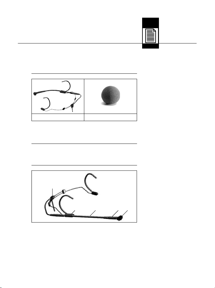
4.2 Windschutz. . . . . . . . . . . . . . . . . . . . . . . . . . . . . . . . . . 9
5 Fehlerbehebung .................................10
6 Technische Daten ................................11
2
AKG C 520/C 520 L
Page 3
1 Sicherheitshinweis/Beschreibung
Überprüfen Sie bitte, ob das Gerät, an das Sie das
Mikrofon anschließen möchten, den gültigen Sicherheitsbestimmungen entspricht und mit einer
Sicherheitserdung versehen ist.
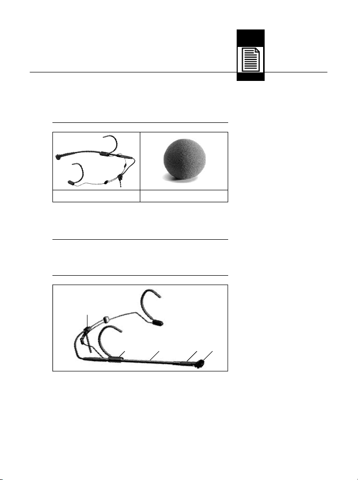
1 x C 520 od. C 520 L 1xW44
Kontrollieren Sie bitte, ob die Verpackung alle
oben angeführten Teile enthält. Falls etwas fehlt,
wenden Sie sich bitte an Ihren AKG-Händler.
• Siehe www.akg.com oder aktuelle MicroMicBroschüre.
• C 520 L: Batteriespeisegerät B 29 L
1.1 Sicherheitshinweis
L
1.2
Lieferumfang
1.3 Optionales
Zubehör
1.4 Kurzbeschreibung
Abb. 1: Mikrofon
C 520/C 520 L
1
Mikrofon mit nierenförmiger Richtcharakteristik für
hohe Rückkopplungssicherheit. Frequenzgang
speziell für Gesang und Querflöte ausgelegt.
2 Elastische Lagerung zur wirkungsvollen Unter-
drückung mechanischer Störgeräusche
AKG C 520/C 520 L
Siehe Abb. 1.
3
Page 4
1 Beschreibung
Siehe Abb. 1 auf
Seite 3.
1.5 C 520
1.6 C 520 L
3
Verstellbarer, abnehmbarer Schwanenhals (125 mm)
zur exakten Positionierung des Mikrofons.
4 Befestigungsclip für Schwanenhals: ermög-
licht links- oder rechtsseitiges Tragen des Mikrofons.
5 Zugentlastung für Mikrofonkabel
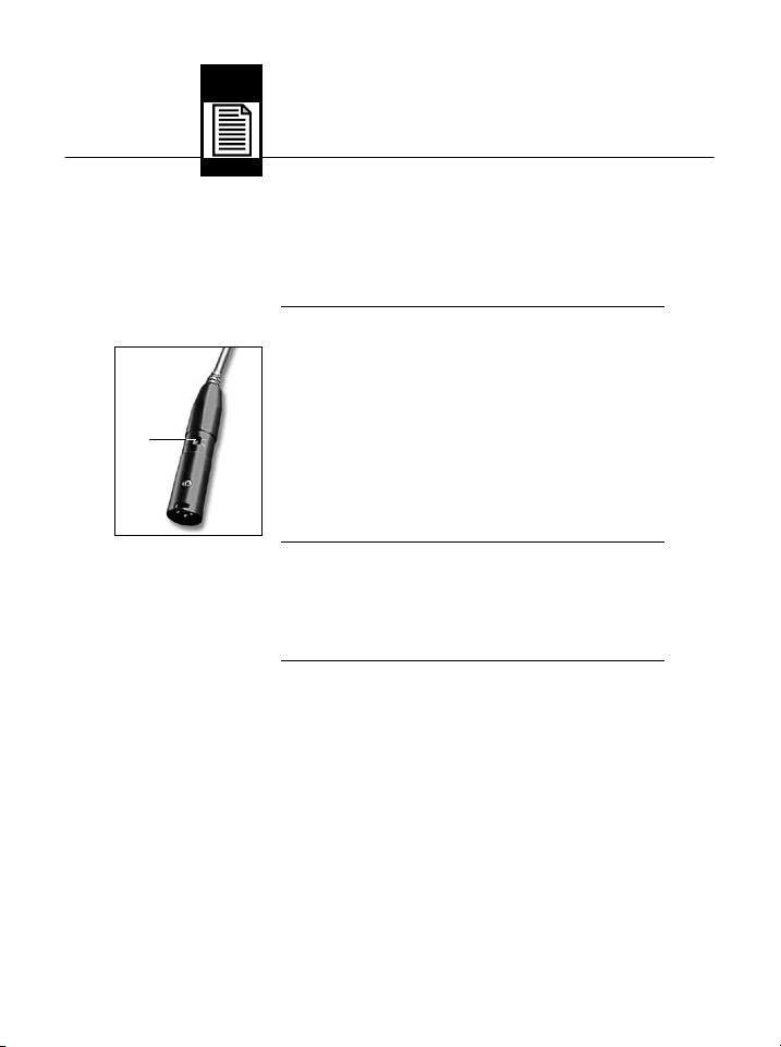
• Für 9 bis 52 V Universal-Phantomspeisung.
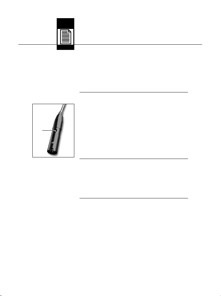
• 3 m langes Anschlusskabel mit Phantomspeiseadapter mit integriertem 3-poligem XLRStecker und schaltbarer Bassabschwächung
(6) (-4 dB bei 100 Hz).
Abb. 1a: Phantomspeiseadapter mit Bassabschwächungsschalter (6)
• Für SpeisungmittelsBatteriespeisegerätB 29 L,
Phantomspeiseadapter MPA V L oder Sender
PT 40, PT 400.
• 1,5 m langes Anschlusskabel mit 3-poligem
Mini-XLR-Stecker.
4
AKG C 520/C 520 L
Page 5
2 Anschluss
Das C 520/C 520 L ist ein Kondensatormikrofon
und benötigt daher eine Stromversorgung.
Wenn Sie andere als die von AKG empfohlenen
Speisegeräte verwenden, kann das Mikrofon
beschädigt werden und erlischt die Garantie.
1. Schließen Sie den Phantomspeiseadapter am
Mikrofonkabel an einen symmetrischen XLRMikrofoneingang mit Phantomspeisung an.
2. Schalten Sie die Phantomspeisung ein. (Lesen
Sie dazu in der Betriebsanleitung des jeweiligen Gerätes nach.)
1. Stecken Sie den Mini-XLR-Stecker am Mikrofonkabel bis zum Anschlag in eine der beiden
Mini-XLR-Buchsen am B 29 L, die Mini-XLRKupplung am Anschlusskabel des MPA V L
bzw. die Eingangsbuchse des Taschensenders
an.
Der Stecker verriegelt sich automatisch.
• Zum Abziehen des Kabels drücken Sie auf
den Entriegelungsknopf am Mini XLR-Stecker
und ziehen Sie den Stecker aus der Buchse
heraus.
• Um das Kabel nicht zu beschädigen, ziehen Sie niemals am Kabel selbst!
2. B29L:Verbinden Sie das B 29 L mit dem
gewünschten Eingang.
MPAVL:Stecken Sie den MPA V L an einen
symmetrischen XLR-Mikrofoneingang mit
Phantomspeisung an und schalten Sie die
Phantomspeisung ein.
2.1 Einleitung
Wichtig!
!
L
2.2 C 520
2.3 C 520 L
Kabel abziehen:
Wichtig!
!
L
AKG C 520/C 520 L
5
Page 6
3 Anwendung
3.1 Mikrofonarm
links oder rechts
montieren
Abb. 2: Mikro-
fonarm abziehen
Siehe Abb. 2.
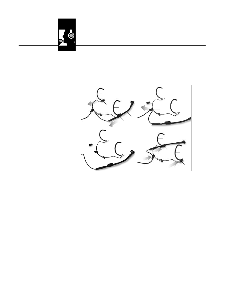
Im Lieferzustand ist der Mikrofonarm rechts am
Nackenbügel befestigt. Die Schnappverbindung
erlaubt Ihnen, den Mikrofonarm auch links am Nackenbügel zu montieren:
1, 2 3 a
3b 4, 5
1. Ziehen Sie die Mikrofonarm-Halterung (2) mit
dem Mikrofonarm (3) in Pfeilrichtung vom Ohrbügel (1) ab.
2. Ziehen Sie die Abdeckung (4) vom anderen
Ohrbügel ab.
3. Ziehen Sie das Kabel aus dem Kabelhalter (5).
4. Schieben Sie die Mikrofonarm-Halterung (2)
und die Abdeckung (4) bis zum Anschlag in
den Drahtbogen unterhalb des jeweils anderen
Ohrbügels (1) ein.
(Die Abdeckung (4) stabilisiert den Ohrbügel
und verhindert, dass sich Haare im Drahtbogen verfangen.)
5. Drücken Sie das Kabel wieder in den Kabelhalter (5) hinein.
6
AKG C 520/C 520 L
Page 7
3 Anwendung
34
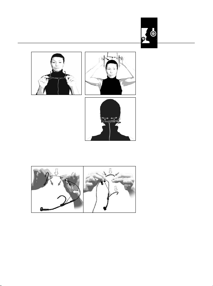
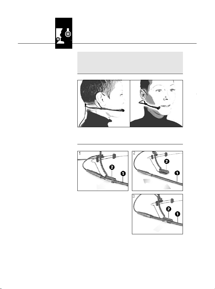
1. Setzen Sie den Nackenbügel wie in
Abb. 3 bis 5 gezeigt
auf.
2. Falls das Mikrofon zu locker sitzt, können Sie
den Nackenbügelund die Ohrbügel nach innen
biegen:
• Halten Sie den Nackenbügel bzw. Ohrbügel
fest an den in Abb. 6 bezeichneten Stellen und
biegen Sie vorsichtig etwas nach innen.
• Probieren Sie, ob das Mikrofon besser sitzt.
Falls nicht, verbiegen Sie den Draht vorsichtig
etwas weiter.
3.2 Mikrofon
aufsetzen
5
Abb. 3 bis 5:
Nackenbügel aufsetzen und enger
stellen
Abb. 6: Nackenbügel und Ohrbügel zurechtbiegen
Siehe Abb. 6.
AKG C 520/C 520 L
7
Page 8

3 Anwendung
Hinweis:
3.3 Mikrofon
positionieren
Abb. 7: Schwanen-
hals einstellen.
Siehe Abb. 7.
3.4 Mikrofonarm
verstellen
Abb. 8: Mikrofon-
arm verstellen
Siehe Abb. 8.
• Nackenbügel und Ohrbügel bestehen aus Federstahldraht. Wenn Sie den Draht zu stark
biegen, kann es sehr schwierig sein, den Draht
in die gewünschte Form zurückzubiegen.
• Stellen Sie den Schwanenhals so ein, dass das
Mikrofon seitlich vor dem Mundwinkel sitzt.
1. Ziehen Sie den
Schwanenhals (1)
aus der Halterung (2)
heraus.
2. Klemmen Sie den
Schwanenhals (1) an
der gewünschten
Stelle wieder in die Halterung (2) ein.
8
AKG C 520/C 520 L
Page 9
3 Anwendung
• Versuchen Sie nie, den Schwanenhals in der
Halterung zu verschieben. Sie würden dadurch den Schwanenhals und/oder die Halterung beschädigen.
4 Reinigung
• Reinigen Sie das Gehäuse des Mikrofons mit
einem mit Wasser befeuchteten Tuch.
• Den Schaumstoff-Windschutz reinigen Sie am
besten mit einer milden Waschmittellösung.
Der Windschutz ist sofort nach dem Trocknen
wieder einsatzbereit.
Wichtig!
!
L
4.1 Mikrofongehäuse
4.2 Windschutz
AKG C 520/C 520 L
9
Page 10

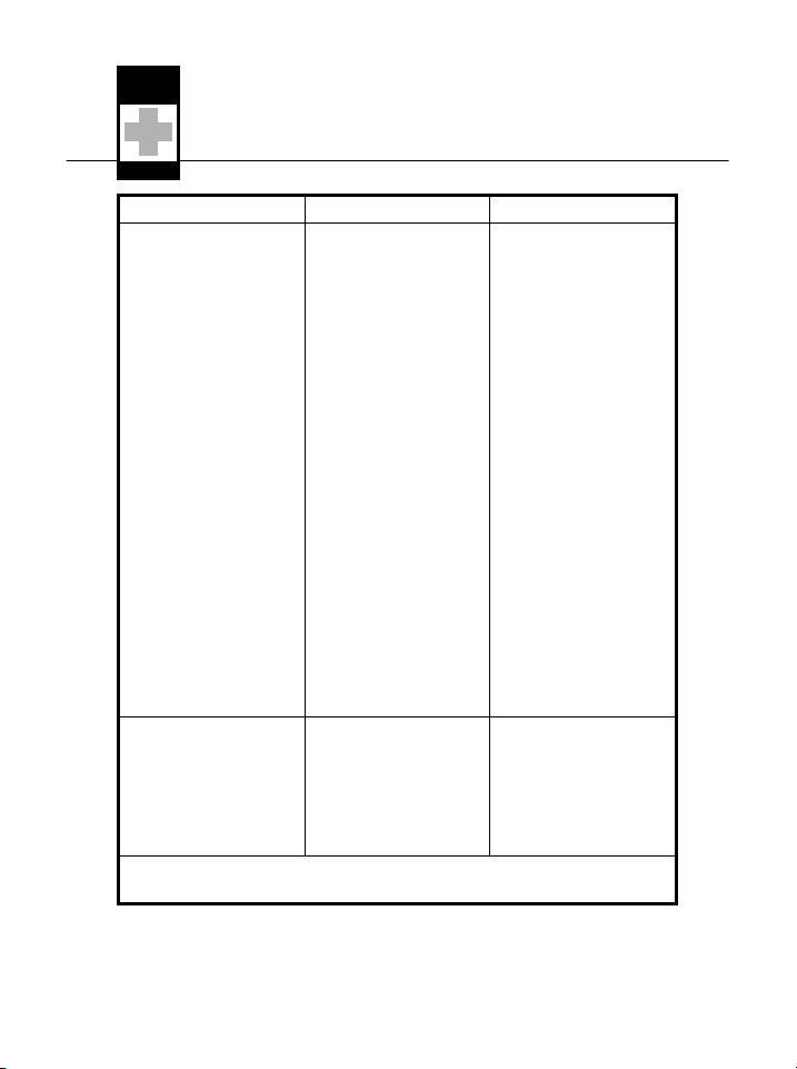
5 Fehlerbehebung
Fehler Mögliche Ursache Abhilfe
Kein Ton: 1. Mischpult und/oder
Verzerrungen: 1. Gain-Regler am
Verstärker ausgeschaltet.
2. Kanal-Fader oder
Summenpegelregler
am Mischpult oder
Lautstärkeregler des
Verstärkers steht auf
Null.
3. Mikrofon nicht an
Mischpult oder
Verstärker angeschlossen.
4. Kabelstecker nicht
richtig angesteckt.
5. Kabel defekt.
6. Keine Speisespannung.
Mischpult zu weit
aufgedreht.
2. Mischpulteingang zu
empfindlich.
1. Mischpult und/oder
Verstärker einschalten.
2. Kanal-Fader oder
Summenpegelregler
am Mischpult oder
Lautstärkeregler des
Verstärkers auf gewünschten Pegel einstellen.
3. Mikrofon an Mischpult oder Verstärker
anschließen.
4. Kabelstecker nochmals anstecken.
5. Kabel überprüfen und
falls nötig ersetzen.
6. Phantomspeisung
einschalten.
Phantomspeisegerät:
ans Netz anschließen
bzw. Batterie(n) einlegen.
Kabel überprüfen und
falls nötig ersetzen.
1. Gain-Regler zurückdrehen.
2. 10-dB-Vorabschwächung zwischen Mikrofonkabel und Eingang stecken.
C520L:Siehe auch Bedienungsanleitung desSenders und Empfängers!
10
AKG C 520/C 520 L
Page 11
6 Technische Daten
Arbeitsweise: Kondensatorwandler mit Permanentladung
Richtcharakteristik: Niere
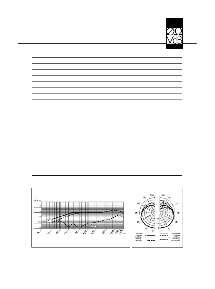
Übertragungsbereich: 20 – 20.000 Hz
Empfindlichkeit: 7 mV/Pa –43 dBV bez. auf 1 V/Pa
Elektrische Impedanz bei 1000 Hz: 200 Ohm
Empfohlene Lastimpedanz: ≥ 2000 Ohm
Grenzschalldruck für 1% / 3% Klirrfaktor: 126 dB / 130 dB
Äquivalentschalldruckpegel: 33 dB (DIN 45412)
Speisespannung: C 520: 9–52 V Phantomspeisung
Stromaufnahme: ca. 2 mA
Kabellänge/Steckerart: C 520: 3 m / XLR 3-polig
Oberfläche: mattschwarz
Abmessungen: 130 mm ø
Netto/Bruttogewicht: C 520: 30 g / 540 g
Dieses Produkt entspricht den in der Konformitätserklärung angeführten
Normen. Sie können die Konformitätserklärung auf http://www.akg.com oder
per E-Mail an sales@akg.com anfordern.
Frequenzgang Polardiagramm
C 520 L: Batteriespeisegerät B 29 L,
Phantomspeiseadapter MPA V L, AKG
WMS Taschensender
C520L:1,5m/Mini-XLR3-polig
C 520 L: 30 g / 471 g
AKG C 520/C 520 L
11
Page 12

Table of Contents
Page
1 Precaution/Description ...........................13
1.1 Precaution. . . . . . . . . . . . . . . . . . . . . . . . . . . . . . . . . . 13
1.2 Packing List . . . . . . . . . . . . . . . . . . . . . . . . . . . . . . . . 13
1.3 Optional Accessories . . . . . . . . . . . . . . . . . . . . . . . . . 13
1.4 Brief Description . . . . . . . . . . . . . . . . . . . . . . . . . . . . . 13
1.5C520 .....................................14
1.6C520L....................................14
2 Interfacing ......................................15
2.1 Introduction . . . . . . . . . . . . . . . . . . . . . . . . . . . . . . . . 15
2.2C520 .....................................15
2.3C520L....................................15
3 Using Your Microphone ...........................16
3.1 Mounting the Microphone Arm on the Left or Right . . 16
3.2 Putting the Micorphone On. . . . . . . . . . . . . . . . . . . . . 17
3.3 Aligning the Microphone. . . . . . . . . . . . . . . . . . . . . . . 18
3.4 Adjusting the Microphone Arm . . . . . . . . . . . . . . . . . . 18
4 Cleaning........................................19
4.1 Micorphone Surface . . . . . . . . . . . . . . . . . . . . . . . . . . 19
4.2 Windscreen. . . . . . . . . . . . . . . . . . . . . . . . . . . . . . . . . 19
5 Troubleshooting .................................20
6 Specifications ...................................21
12
AKG C 520/C 520 L
Page 13
1 Precaution/Description
Please make sure that the piece of equipment
your microphone will be connected to fulfills the
safety regulations in force in your country and is
fitted with a ground lead.
1 x C 520 or C 520 L 1xW44
Check that the packaging contains all of the components listed above. Should anything be missing, please contact your AKG dealer.
• Visit www.akg.com or refer to the latest
MicroMic brochure.
• C 520 L: B 29 L battery power supply
1.1 Precaution
L
1.2 Packing List
1.3 Optional
Accessories
1.4 Brief
Description
Fig. 1: C 520/
C 520 L microphone.
1 Cardioid microphone for high gain before feed-
back. Frequency response tailored to vocal
use and flute miking.
2 Shock mount reduces handling and cable
noise.
AKG C 520/C 520 L
Refer to fig. 1.
13
Page 14

1 Description
Refer to fig. 1
on page 13.
1.5 C 520
1.6 C 520 L
3 Adjustable, detachable 5-inch (125-mm)
gooseneck for precise microphone positioning.
4 Removable microphone arm holder for placing
the microphone to the left or right of your
mouth.
5 Microphone cable strain relief.
• For 9 to 52 V universal phantom power.
• 10-ft. (3-m) plug-in connecting cable with
phantom power adapter with integrated 3-pin
XLR connector and switchable bass rolloff (6)
(-4 dB at 100 Hz).
Fig. 1a: Phantom power adapter
with bass rolloff switch (6).
• For use with the B 29 L battery power supply,
MPA V L phantom power adapter, or PT 40 or
PT 400 transmitters.
• 5-ft. (1.5-m) plug-in connecting cable with 3pin mini XLR connectors.
14
AKG C 520/C 520 L
Page 15
a
2 Interfacing
The C 520 /C 520 L is a condenser microphone
and therefore needs a power supply.
Using any power supply other than those recommended by AKG may damage your microphone and will void the warranty.
1. Connect the phantom power adapter on the
microphone cable to a balanced XLR microphone input with phantom power.
2. Switch the phantom power on. (Refer to the
instruction manual of the unit to which you
connected your C 420.)
1. Plug the mini XLR connector on the microphone cable all the way into one of the two mini
XLR sockets on the B 29, the mini XLR socket
on the connecting cable of the MPA II, or the
input socket on the bodypack transmitter.
The connector will lock automatically.
• To disconnect the cable, press the unlocking
button on the mini XLR connector and pull the
connector out of the socket.
void ddamaging tthe ccable, nnever ppull aat
To a
•
the ccable iitself!
2. B 29 L: Connect the B 29 L to the desired input.
MPA V L: Connect the MPA V L to a balanced
XLR microphone input with phantom power
and switch the phantom power on.
2.1 Introduction
Important!
!
L
2.2 C 520
2.3 C 520 L
2.3.1 B 29 L or
MPA V L
Disconnecting
the cable:
Important!
!
L
AKG C 520/C 520 L
15
Page 16

3 Using Your Microphone
3.1 Mounting
the Microphone
Arm on the Left
or Right
Fig. 2: Removing
the microphone
arm.
Refer to fig. 2.
As delivered, the microphone arm is fitted on the
right side of the behind-the-neck headband. To
mount the microphone arm on the left side of the
headband:
1, 2 3 a
3b 4, 5
1. Pull the microphone arm holder (2) with the microphone arm (3) from the temple piece (1) in
the direction of the arrow.
2. Remove the cover (4) from the other temple
piece.
3. Remove the cable from the cable holder (5).
4. Insert the microphone arm holder (2) and the
cover (4) all the way into the respective wire
loop below the opposite temple piece (1).
(The cover (4) stabilizes the temple piece and
prevents your hair from getting caught in the
wire loop.)
5. Press the cable back into the cable holder (5).
16
AKG C 520/C 520 L
Page 17

3 Using Your Microphone
34
1. Put the behind-theneck headband on
as shown in figs. 3
through 5.
2. Should the microphone fit loosely, you may
bend the behind-the-neck headband and the
temple pieces inward:
• Hold the headband or temple piece firmly at
the points marked in fig. 6 and bend inward
with extreme care.
• Check whether the microphone fits better. If it
does not, bend the wire some more, again with
extreme care.
3.1 Putting the
Microphone on
5
Figs. 3 to 5: Putting
on and tightening
the headband.
Fig. 6: Bending the
headband and
temple pieces
to fit.
Refer to fig. 6.
AKG C 520/C 520 L
17
Page 18
Note:
3.3 Aligning the
Microphone
Fig. 7: Adjusting
the gooseneck.
Refer to fig. 7.
3.4 Adjusting the
Microphone Arm
Fig. 8: Adjusting
the microphone
arm.
3 Using Your Microphone
• Both the headband and temple pieces are
made of spring steel wire. If you bend the wire
too hard it may be extremely difficult to bend
the wire back to the desired shape.
• Adjust the gooseneck so as to point the microphone at the corner of your mouth.
Refer to fig. 8.
18
1. Unsnap the gooseneck (1) from the
holder (2).
2. Snap the gooseneck
(1) back into the
holder (2) at the
desired position.
AKG C 520/C 520 L
Page 19
3 Using Your Microphone
• Never try to shift the gooseneck inside the
holder. This would damage the gooseneck
and/or holder.
4 Cleaning
• To clean the microphone surface, use a soft
cloth moistened with water.
• Clean the foam windscreen in mild soap suds.
You can use the windscreen again as soon as it
has dried.
Important!
!
L
4.1 Microphone
Surface
4.2 Windscreen
AKG C 520/C 520 L
19
Page 20
5 Troubleshooting
Problem Possible Cause Remedy
No sound: 1. Power to mixer
and/or amplifier is off.
2. Channel or master
fader on mixer, or volume control on amplifier is at zero.
3. Microphone is not
connected to mix er
or amplifier.
4. Cable connectors are
seated loosely.
5. Cable is defective.
6. No supply voltage.
1. Switch power to
mixer or amplifier on.
2. Set channel or master fader on mixer or
volume control on
amplifier to desired lev el.
3. Connect microphone
to mixer or amplifier.
4. Check cable connectors for secure seat.
5.
Check cable and replace if damaged.
6. Switch phantom
power on.
Phantom power supply: connect to power
outlet or insert battery
(batteries).
Check cable and replace if necessary.
20
Distortion: 1. Gain control on the
mixer set too high.
2. Mixer input sensitivity
too high.
C 520 L: Also read the transmitter and receiver manuals!
1. Turn gain control
down CCW.
2. Connect a 10-dB
preattenuation pad
between microphone
cable and input.
AKG C 520/C 520 L
Page 21

6 Specifications
Type: pre-polarized condenser microphone
Polar pattern: cardioid
Frequency range: 20 Hz to 20,000 Hz
Sensitivity: 7 mV/Pa -43 dBV re 1 V/Pa
Electrical Impedance at 1000 Hz: 200 ohms
Recommended load impedance: ≥ 2000 ohms
Max. SPL for 1% / 3% THD: 126 dB / 130 dB
Equivalent noise level: 33 dB (to DIN 45412)
Supply voltage: C 520: 9 to 52 V universal phantom power
Current consumption: approx. 2 mA
Cable length/Connector: C 520: 3 m (10 ft.) / 3-pin male XLR
Finish: matte black
Size: 130 mm (5.2 in.) in dia.
Net/shipping weight: C 520: 30 g/540 g (1.1/19.1 oz.)
This product conforms to the standards listed in the Declaration of Conformity.
To order a free copy of the Declaration of Conformity, visit http://www.akg.com or
contact sales@akg.com.
Frequency Response Polar Diagram
C 520 L: 9 V battery supply through B 29 L
or bodypack transmitter, or 9 to 52 V universal phantom power through MPA V L
adapter
C 520 L: 1.5 m (5 ft.) / 3-pin mini XLR
C 520 L: 30 g/471 g (1.1/16.6 oz.)
AKG C 520/C 520 L
21
Page 22

Table des matières
Page
1 Consigne de sécurité / Description . . . . . . . . . . . . . . . . . . 23
1.1 Consigne de sécurité . . . . . . . . . . . . . . . . . . . . . . . . . 23
1.2 Fournitures . . . . . . . . . . . . . . . . . . . . . . . . . . . . . . . . . 23
1.3 Accessoires opcionnels . . . . . . . . . . . . . . . . . . . . . . . 23
1.4 Description succincte . . . . . . . . . . . . . . . . . . . . . . . . . 23
1.5 C 520 . . . . . . . . . . . . . . . . . . . . . . . . . . . . . . . . . . . . . 24
1.6 C 520 L . . . . . . . . . . . . . . . . . . . . . . . . . . . . . . . . . . . . 24
2 Raccordement . . . . . . . . . . . . . . . . . . . . . . . . . . . . . . . . . . 25
2.1 Introduction . . . . . . . . . . . . . . . . . . . . . . . . . . . . . . . . 25
2.2 C 520 . . . . . . . . . . . . . . . . . . . . . . . . . . . . . . . . . . . . . 25
2.3 C 520 L . . . . . . . . . . . . . . . . . . . . . . . . . . . . . . . . . . . . 25
3 Utilisation . . . . . . . . . . . . . . . . . . . . . . . . . . . . . . . . . . . . . . 26
3.1 Monter le bras de micro à droite ou à gauche . . . . . . . 26
3.2 Pour mettre l’arceau . . . . . . . . . . . . . . . . . . . . . . . . . . 27
3.3 Positionner le microphone . . . . . . . . . . . . . . . . . . . . . 28
3.4 Régler le bras de micro . . . . . . . . . . . . . . . . . . . . . . . . 28
4 Nettoyage . . . . . . . . . . . . . . . . . . . . . . . . . . . . . . . . . . . . . . 29
4.1 Boîtier . . . . . . . . . . . . . . . . . . . . . . . . . . . . . . . . . . . . . 29
4.1 Bonnette antivent . . . . . . . . . . . . . . . . . . . . . . . . . . . . 29
5 Dépannage . . . . . . . . . . . . . . . . . . . . . . . . . . . . . . . . . . . . . 30
6 Caractéristiques techniques . . . . . . . . . . . . . . . . . . . . . . . 31
22
AKG C 520/C 520 L
Page 23

1 Consigne de sécurité / Description
Vérifiez si l’appareil auquel vous voulez raccorder
le microphone répond aux prescriptions relatives
à la sécurité en vigueur et s’il possède une mise à
la terre de sécurité.
1 x C 520 ou C 520 L 1 x W 44
Contrôlez si le carton contient bien tous les éléments énumérés ci-dessus. Si ce n’est pas le cas,
veuillez contacter votre distributeur AKG.
• Voir www.akg.com ou la brochure MicroMic la
plus récente.
• C 520 L: Alimentation batterie B 29 L
1 Microphone à caractéristique cardioïde pour
une haute protection contre le larsen. Réponse
en fréquence spécialement adaptée à la prise
de la voix et de la flûte traversière.
2 Suspension élastique pour suppression efficace
des bruits mécaniques.
AKG C 520/C 520 L
1.1 Consigne de
sécurité
L
1.2 Fournitures
1.3 Accessoires
optionnels
1.4 Description
succincte
Fig. 1: Microphone
C 520/C 520 L
23
Page 24

1 Description
Voir Fig. 1,
page 23.
1.5 C 520
C 520 L
3 Col-de-cygne réglable, démontable (125 mm)
pour un positionnement précis du micro.
4 Clip de fixation du col-de-cygne : permet de
porter le micro à droite ou à gauche.
5 Dispositif permettant d’éviter une traction sur
le câble de micro.
• Pour alimentation fantôme universelle de 9 à
52 V.
• Câble de raccordement de 3 m de long
connectable avec adaptateur pour alimentation fantôme, avec connecteur XLR à 3 points
et atténuation des graves commutable (6)
(-4 dB à 100 Hz).
Fig. 1a: Adaptateur pour alimentation fantôme
avec commutateur d’atténuation des graves (6)
• Pour alimentation par boîtier à pile B 29 L, mo-
dule d’alimentation fantôme MPA V L ou émetteur de poche PT 40 ou PT 400.
• Câble de raccordement enfichable de 1,5 m de
long, avec connecteur mini-XLR 3 points.
24
AKG C 520/C 520 L
Page 25

d
n
2 Raccordement
Le C 520/C 520 L est un microphone électrostatique ; il a donc besoin d’une alimentation.
L’utilisation d
recommandées ppar AAKG ppeut pprovoquer ddes
dégâts ssur lle mmicro eet eentraîne lla pperte dde lla
garantie.
1. Connectez l’adaptateur pour alimentation
fantôme du câble micro sur une entrée de
micro symétrique type XLR avec alimentation
fantôme.
2. Mettez l’alimentation fantôme sous tension
(Veuillez vous reporter à la notice de l’alimentation utilisée).
1. Enfoncez le connecteur XLR miniature du
câble micro jusqu’en butée dans une des deux
embases miniature type XLR de l’alimentation
B 29 L, dans l’accouplement XLR miniature du
câble de raccordement du MPA V L ou dans
l’embase d’entrée de l’émetteur de poche.
Le connecteur se verrouille automatiquement.
• Pour détacher le câble, appuyez sur le bouton
de déverrouillage du connecteur mini-XLR (1)
et sortez le connecteur de la prise.
Pour n
•
sortez jjamais lle cconnecteur een ttirant ssur lle
câble.
2. B 29 L: Raccordez le B 29 L sur l’entrée voulue.
MPA V L: Connectez le MPA V L sur une entrée
de micro symétrique type XLR avec alimentation fantôme et mettez l’alimentation fantôme
sous tension.
’alimentations aautres qque ccelles
e ppas rrisquer dd’abîmer lle ccâble, nne
2.1 Introduction
Important !
!
L
2.2 C 520
2.3 C 520 L
2.3.1 B 29 L ou
MPA V L
Débrancher le
câble :
Important !
!
L
AKG C 520/C 520 L
25
Page 26

3 Utilisation
3.1 Monter le
bras de micro à
droite ou à
gauche
Fig. 2 : Déposer le
bras de micro
Voir Fig. 2.
A la livraison, le bras de micro est monté sur la
droite de l’arceau se portant sur la nuque. Vous
pouvez aisément le changer de côté grâce à la
fixation à déclic :
1, 2 3 a
3b 4, 5
1. Faites glisser le support de bras de micro (2)
avec le bras de micro (3) dans le sens de la
flèche pour le détacher de la branche de l’arceau reposant sur l’oreille (1).
2. Enlevez l’embout (4) de l’autre banche.
3. Sortez le câble de l’attache (5).
4. Inversez le support de bras de micro (2) et
l’embout (4) et enfoncez-les jusqu’en butée sur
l’arceau au-dessous de la branche (1) respective.
(L’embout (4) stabilise la branche et empêche
que les cheveux ne se prennent dans le fil de
l’arceau.)
5. Enfoncez le câble dans l’attache (5).
26
AKG C 520/C 520 L
Page 27

3 Utilisation
34
1.
Mettez l’arceau comme
indiqué aux Fig. 3 à 5.
2. Si le micro n’est pas suffisamment stable vous
pouvez recourber l’arceau et les branches
pour les serrer :
• Maintenez fermement l’arceau ou la branche à
l’endroit indiqué à la Fig. 6 et courbez-les avec
précautions vers l’intérieur.
• Essayez si le micro tient mieux. Si ce n’est pas
le cas courbez encore un peu plus le fil métallique, toujours avec précautions.
3.2 Pour mettre
l’arceau
5
Fig. 3 à 5 : Comment mettre l’arceau sur la nuque
et le resserrer
Fig. 6 : Recourber
l’arceau et les
branches
Voir Fig. 6.
AKG C 520/C 520 L
27
Page 28

3 Utilisation
Remarque :
3.3 Positionner
le microphone
Fig. 7 : Réglage du
col-de-cygne
Voir Fig. 7.
3.4 Réglage du
bras de micro
Fig. 8 : Réglage du
bras de micro
Voir Fig. 8.
• L’arceau et les branches sont en fil d’acier à
ressorts. Si vous courbez excessivement le fil
vous risquez d’avoir des difficultés à le
ramener à la forme souhaitée.
• Réglez le col-de-cygne pour positionner le
microphone devant la commissure des lèvres.
1. Sortez le col-decygne (1) du support
(2).
2. Fixez le col-decygne (1) dans le
support (2) à la position souhaitée.
28
AKG C 520/C 520 L
Page 29

3 Utilisation
• N’essayez jamais de faire glisser le col-decygne dans le support. Vous risqueriez
d’abîmer le col-de-cygne ou le support,
voire les deux.
4 Nettoyage
• Le boîtier du micro se nettoie avec un chiffon
légèrement humide (eau claire).
• La bonnette antivent se lave à l’eau savonneuse en utilisant un produit doux. La bonnette
peut être réutilisée dès qu’elle est sèche.
Important !
!
L
4.1 Boîtier
4.2 Bonnette
antivent
AKG C 520/C 520 L
29
Page 30

5 Dépannage
Problème
Pas de son : 1. La console de mixage
Distorsions : 1. Le réglage de gain de la ta-
C 520 L: Veuillez vous reporter aussi aux notices d’emploi
Cause possible Remède
et/ou l’amplificateur ne
sont pas sous tension.
2. Le fader du canal ou le
réglage de niveau master
de la console de mixage ou
le réglage de niveau sonore de l’ampli est sur
zéro.
3. Le micro n’est pas
connecté à la console de
mixage ou à l’ampli.
4. La fiche est mal enfoncée.
5. Le câble est abîmé.
6. Pas de tension d’alimentation.
ble de mixage est trop
haut.
2. L’entrée de la table de
mixage est trop sensible.
de l’émetteur et du récepteur !
1. Mettre la console de
2. Régler le fader du canal ou
3. Connecter le micro à la
4. Enfoncer la fiche correcte-
5. Contrôler le câble et le
6. Mettre l’alimentation
1. Baisser le réglage de gain.
2. Insérer un pré-atténuateur
mixage et/ou l’amplificateur sous tension.
le réglage de niveau master de la console de
mixage ou le réglage de niveau sonore de l’ampli sur
la valeur voulue.
console de mixage ou à
l’ampli.
ment.
remplacer le cas échéant.
fantôme sous tension.
Appareil d’alimentation
fantôme : brancher sur le
secteur ou mettre une (des)
pile(s).
Contrôler le câble et le
remplacer le cas échéant.
de sensibilité entre le câble
du micro et l’entrée.
30
AKG C 520/C 520 L
Page 31

6 Caractéristiques techniques
Fonctionnement : microphone électrostatique à charge per-
Directivité : cardioïde
Réponse en fréquence : 20 … 20.000 Hz
Sensibilité : 7 mV/Pa -43 dBV rapp. à 1 V/Pa
Impédance électrique à 1.000 Hz : 200 ohms
Impédance de charge recommandée : ≥ 2000 ohms
Niveau maximum de pression sonore pour un facteur
de distorsion de 1% / 3% : 126 / 130 dB SPL
Niveau de bruit équivalent : 33 dB (selon DIN 45412)
Tension d’alimentation : C 520 : 9 … 52 V, al. fantôme universelle
Consommation : env. 2 mA
Longueur du câble / connecteur : C 520 : 3 m / type XLR, 3 points
Couleur : noir mat
Dimensions : 130 mm (diamètre)
Poids net/brut : C 520 : 30 g / 540 g
Ce produit est conforme aux normes citées dans la Déclaration de Conformité,
dont vous pouvez prendre connaissance en consultant le site
http://www.akg.com ou en adressant un e-mail à sales@akg.com.
manente
C 520 L : alimentation à piles B 29 L,
adaptateur fantôme MPA V L,
émetteurs de poche AKG WMS
C 520 L : 1,5 m / type mini-XLR, 3 points
C 520 L : 30 g / 471 g
Réponse en fréquence Diagramme polaire
AKG C 520/C 520 L
31
Page 32
Indice
Pagina
1 Indicazione per la sicurezza / Descrizione . . . . . . . . . . . . 33
1.1 Indicazione per la sicurezza . . . . . . . . . . . . . . . . . . . . 33
1.2 In dotazione . . . . . . . . . . . . . . . . . . . . . . . . . . . . . . . . 33
1.3 Accessori opzionali. . . . . . . . . . . . . . . . . . . . . . . . . . . 33
1.4 Breve descrizione . . . . . . . . . . . . . . . . . . . . . . . . . . . . 33
1.5 C 520 . . . . . . . . . . . . . . . . . . . . . . . . . . . . . . . . . . . . . 34
1.6 C 520 L . . . . . . . . . . . . . . . . . . . . . . . . . . . . . . . . . . . . 34
2 Collegamento . . . . . . . . . . . . . . . . . . . . . . . . . . . . . . . . . . . 35
2.1 Introduzione . . . . . . . . . . . . . . . . . . . . . . . . . . . . . . . . 35
2.2 C 520 . . . . . . . . . . . . . . . . . . . . . . . . . . . . . . . . . . . . . 35
2.3 C 520 L . . . . . . . . . . . . . . . . . . . . . . . . . . . . . . . . . . . . 35
3 Impiego . . . . . . . . . . . . . . . . . . . . . . . . . . . . . . . . . . . . . . . . 36
3.1
Come montare il braccio microfonico a sinistra o a destra . . 36
3.2 Come indossare il microfono . . . . . . . . . . . . . . . . . . . 37
3.3 Posizionare il microfono . . . . . . . . . . . . . . . . . . . . . . . 38
3.4 Come regolare il braccio microfonico . . . . . . . . . . . . . 38
4 Pulizia . . . . . . . . . . . . . . . . . . . . . . . . . . . . . . . . . . . . . . . . . 39
4.1 Scatola del microfono . . . . . . . . . . . . . . . . . . . . . . . . . 39
4.2 Antisoffio. . . . . . . . . . . . . . . . . . . . . . . . . . . . . . . . . . . 39
5 Eliminazione di difetti . . . . . . . . . . . . . . . . . . . . . . . . . . . . . 40
6 Dati tecnici. . . . . . . . . . . . . . . . . . . . . . . . . . . . . . . . . . . . . . 41
32
AKG C 520/C 520 L
Page 33

1 Indicazione per la sicurezza/Descrizione
Controllate per favore se l’apparecchio che volete
collegare al microfono corrisponde alle norme di
sicurezza vigenti e se è dotato di una messa a
terra di sicurezza.
1 x C 520 o C 520 L 1 x W 44
Controllate per favore se la confezione contiene
tutti i componenti di cui sopra. Se manca qualcosa rivolgetevi al vostro rivenditore AKG.
• Vedi www.akg.com o l’attuale depliant MicroMic.
• C 520 L: alimentatore a batteria B 29 L
1.1 Indicazione
per la sicurezza
L
1.2 In dotazione
1.3 Accessori
opzionali
1.4 Breve
descrizione
Fig. 1: Microfono
C 520/C 520 L
1 Microfono a direttività cardioide per alta sicurezza
contro il feedback. Risposta in frequenza ideata
specialmente per la voce ed il flauto traverso.
2 Supporto elastico per efficiente soppressione dei
rumori meccanici disturbanti.
AKG C 520/C 520 L
Vedi fig.1.
33
Page 34

1 Descrizione
a pagina 33.
1.5 C 520
1.6 C 520 L
Vedi fig. 1
3 Collo di cigno regolabile, staccabile (125 mm),
per posizionare il microfono in modo preciso.
4 Clip di fissaggio per il collo di cigno: permette
di portare il microfono dal lato sinistro o da
quello destro.
5 Dispositivo anti-trazione per il cavo microfo-
nico.
• Per alimetazione phantom universale da 9 a 52 V.
• Cavo di collegamento lungo 3 m, innestabile,
con adattatore per alimentazione phantom con
connettore XLR a 3 poli integrato e attenuazione dei bassi regolabile (6) (-4 dB a 100 Hz).
Fig. 1a: Adattatore per alimentazione phantom
con interruttore per l’attenuazione dei bassi (6)
• Per alimentazione mediante alimentatore a
batterie B 29 L, adattatore per alimentazione
phantom MPA V L oppure trasmettitore da tasca PT 40 o PT 400.
• Cavo di collegamento lungo 1,5 m, innestabile,
con connettore mini-XLR a 3 poli.
34
AKG C 520/C 520 L
Page 35

2 Collegamento
Il C 520/C 520 L è un microfono a condensatore e
ha quindi bisogno di alimentazione.
Se usate alimentatori diversi da quelli raccomandati dall’AKG, il microfono può subire
danni e la garanzia si estingue.
1. Collegate l’adattatore per l’alimentazione
phantom disposto sul cavo microfonico a un
ingresso microfonico XLR simmetrico con alimentazione phantom.
2. Inserite l’alimentazione phantom. (Leggete in
merito le istruzioni per l’uso del rispettivo
apparecchio.)
1. Collegate la presa d’uscita disposta sul collo di
cigno ad una delle due prese mini-XLR disposte sul B 29 L o all’accoppiamento mini-XLR disposto sul cavo di collegamento del MPA V L,
servendovi del cavo di collegamento in dotazione.
• Per sfilare il cavo, premete il bottone di sblocco
sul connettore mini-XLR e sfilate il connettore
dalla presa.
• Per non danneggiare il cavo, non esercitate
mai trazione direttamente sul cavo!
2. B 29 L: Collegate il B 29 L (con l’ingresso pre-
scelto.
MPA V L: Collegate l’MPA V L a un ingresso microfonico XLR simmetrico con alimentazione
phantom e inserite l’alimentazione phantom.
2.1 Introduzione
Importante!
!
L
2.2 C 520
2.3 C 520 L
Sfilare il cavo:
Importante!
!
L
AKG C 520/C 520 L
35
Page 36

3 Impiego
3.1 Come montare il braccio
microfonico a
sinistra o a
destra
Fig. 2: Come
sfilare il braccio
microfonico
Vedi fig. 2.
Il microfono viene consegnato fissato dalla parte
destra dell’archetto sottonucale. Il collegamento a
scatto vi permette di montare il microfono anche
dalla parte sinistra dell’archetto sottonucale:
1, 2 3 a
3b 4, 5
1. Sfilate il dispositivo di fissaggio del braccio microfonico (2) con il braccio microfonico (3) dall’archetto auricolare (1) in direzione della freccia.
2. Sfilate la copertura (4) dall’altro archetto auricolare.
3. Sfilate il cavo dal dispositivo di fissaggio del
cavo (5).
4. Infilate il dispositivo di fissaggio del braccio microfonico (2) e la copertura (4) fino all’arresto
nell’archetto metallico al di sotto del rispettivamente altro archetto auricolare (1).
(La copertura (4) stabilizza l’archetto auricolare
e evita che i capelli si intreccino nell’archetto
metallico.)
5. Premete di nuovo il cavo nel dispositivo di fissaggio (5).
36
AKG C 520/C 520 L
Page 37

3 Impiego
34
1. Indossate l’archetto
dietro la nuca come
indicato nelle figg. 3-5.
2. Se il microfono non aderisce bene alla testa,
potete piegare l’archetto sottonucale e gli archetti auricolari verso l’interno:
• Tenete l’archetto sottonucale rispettivamente
l’archetto auricolare fermi nei punti indicati
nella fig. 6 e piegateli prudentemente un po’
verso l’interno.
• Provate se la posizione del microfono è più
conveniente. Se no, piegate il filo prudente-
mente un po’ di più.
AKG C 520/C 520 L
3.2 Come indossare il microfono
5
Fig. 3 a 5: Come
infilare e stringere
l’archetto sotto nucale
Fig. 6: Come
piegare l’archetto
sottonucale e l’archetto auricolare
Vedi fig. 6.
37
Page 38

3 Impiego
Avvertenza:
3.3 Posizionare il
microfono
Fig. 7:
Regolazione del
collo di cigno
Vedi fig. 7.
3.4 Come regolare il braccio
microfonico
Fig. 8: Come
regolare il braccio
microfonico
Vedi fig. 8.
• L’archetto sottonucale e gli archetti auricolari
sono realizzati in acciaio elastico. Se piegate il
filo troppo forte, potrete avere delle difficoltà a
ripiegarlo nella forma desiderata.
• Piegate il collo di cigno in modo che il mi-
crofono si trovi lateralmente davanti all’angolo
della bocca.
1. Sfilate il collo di cigno (1) dal dispositivo di fissaggio (2).
2. Reinfilate il collo di
cigno (1) nel punto
prescelto nel dispositivo di fissaggio (2).
38
AKG C 520/C 520 L
Page 39

3 Impiego
• Non cercate mai di spostare il collo di cigno
mentre si trova ancora nel dispositivo di fissaggio; in questo modo danneggereste il
collo di cigno e/o il dispositivo di fissaggio.
4 Pulizia
• Pulite la scatola del microfono con un panno
inumidito con acqua.
• L‘antisoffio in espanso viene pulito preferibilmente con una blanda soluzione detersiva;
appena asciugato, l‘antisoffio è subito pronto
all'uso.
Importante:
!
L
4.1 Scatola del
microfono
4.2 Antisoffio
AKG C 520/C 520 L
39
Page 40

5 Eliminazione di difetti
Difetto Possibili cause Rimedio
Nessun suono: 1. Mixer e/o amplificatore
Distorsioni: 1. Il regolatore gain sul
C 520 L: Vedi anche le istruzioni per l’uso per il trasmettitore e del ricevitore!
sono dis inseriti.
2. Fader del canale o regolatore principale del mixer
o regolatore del volume
dell’amplificatore sono in
posizione zero.
3. Il microfono non è collegato al mixer o all’amplificatore.
4. Il connettore del cavo
non è inserito bene.
5. Il cavo è difettoso.
6. Non c’è alimentazione.
mixer è aperto troppo.
2. L’ingresso del mixer è
troppo sensibile.
1. Inserire il mixer e/o l’amplificatore.
2. Portare al livello desiderato il fader del canale o il
regolatore principale del
mixer o il regolatore del
volume dell’amplificatore.
3. Collegare il microfono al
mixer o all’amplificatore.
4. Inserire di nuovo il connettore del cavo.
5. Controllare il cavo e sostituirlo se necessario.
6. Inserire l’alimentazione
phantom.
Alimentatore phantom:
collegarlo alla rete oppure inserire batteria(e).
Controllare il cavo e, se
necessario, sostituirlo.
1. Portare indietro il regolatore gain.
2. Inserire un preattenuatore
di 10 dB tra cavo microfonico ed ingresso.
40
AKG C 520/C 520 L
Page 41

6 Dati tecnici
Modo di funzionamento: microfono a condensatore con carica per-
Direttività: cardioide
Risposta in frequenza: 20 - 20.000 Hz
Sensibilità: 7 mV/Pa -43 dBV rif. a 1 V/Pa
Impedenza elettrica a 1000 Hz: 200 ohm
Impedenza di carico raccomandata: ≥ 2000 ohm
Livello di pressione acustica limite per un coefficiente di distorsione armonica
di 1% / 3%: 126 / 130 dB SPL
Livello di pressione acustica equivalente: 33 dB (secondo DIN 45412)
Tensione di alimentazione: C 520: al. phantom universale 9 - 52 V
Assorbimento: 2 mA circa
Lunghezza del cavo / connettore: C 520: 3 m / XLR a 3 poli
Superficie: nero opaco
Dimensioni: 130 mm (diametro)
Peso netto/lordo: C 520: 30 g / 540 g
Questo prodotto corrisponde alle norme elencate nella dichiarazione di conformità, che è disponibile al sito http://www.akg.com oppure all'indirizzo email
sales@akg.com.
manente
C 520 L: alimentatore a batterie B 29 L,
adattatore phantom MPA V L, trasmettitori
da tasca AKG WMS
C 520 L: 1,5 m / mini-XLR a 3 poli
C 520 L: 30 g / 471 g
Risposta in frequenza Diagramma polare
AKG C 520/C 520 L
41
Page 42

Indice
Página
1 Indicaciones de seguridad/Descripción . . . . . . . . . . . . . . 43
1.1 Indicaciones de seguridad . . . . . . . . . . . . . . . . . . . . . 43
1.2 Volumen de suministros . . . . . . . . . . . . . . . . . . . . . . . 43
1.3 Accesorios opcionales . . . . . . . . . . . . . . . . . . . . . . . . 43
1.4 Breve descripción. . . . . . . . . . . . . . . . . . . . . . . . . . . . 43
1.5 C 520 . . . . . . . . . . . . . . . . . . . . . . . . . . . . . . . . . . . . . 44
1.6 C 520 L . . . . . . . . . . . . . . . . . . . . . . . . . . . . . . . . . . . . 44
2 Conexión . . . . . . . . . . . . . . . . . . . . . . . . . . . . . . . . . . . . . . . 45
2.1 Introducción . . . . . . . . . . . . . . . . . . . . . . . . . . . . . . . . 45
2.2 C 520 . . . . . . . . . . . . . . . . . . . . . . . . . . . . . . . . . . . . . 45
2.3 C 520 L . . . . . . . . . . . . . . . . . . . . . . . . . . . . . . . . . . . . 45
3 Utilización . . . . . . . . . . . . . . . . . . . . . . . . . . . . . . . . . . . . . . 46
3.1
Montar el brazo del micrófono a la derecha o a la izquierda
3.2 Colocarse el micrófono . . . . . . . . . . . . . . . . . . . . . . . . 47
3.3 Posicionar el micrófono . . . . . . . . . . . . . . . . . . . . . . . 48
3.4 Cambiar la posición del brazo del micrófono . . . . . . . 48
4 Limpieza . . . . . . . . . . . . . . . . . . . . . . . . . . . . . . . . . . . . . . . 49
4.1 Caja del micrófono . . . . . . . . . . . . . . . . . . . . . . . . . . . 49
4.2 Pantalla antiviento. . . . . . . . . . . . . . . . . . . . . . . . . . . . 49
5 Eliminación de fallos. . . . . . . . . . . . . . . . . . . . . . . . . . . . . . 50
6 Datos técnicos . . . . . . . . . . . . . . . . . . . . . . . . . . . . . . . . . . 51
. 46
42
AKG C 520/C 520 L
Page 43

1 Indicaciones de seguridad/Descripción
Sírvase verificar si el aparato al cual quiere conectar el micrófono cumple con las disposiciones de
seguridad vigentes y está equipado con una toma
de tierra de seguridad.
1 x C 520 1 x W 44
Sírvase controlar si el embalaje contiene todas las
piezas indicadas arriba. Si falta algo, le rogamos
dirigirse a su distribuidor AKG.
• Sírvase consultar www.akg.com o el más reciente folleto sobre MicroMic.
• C 520 L: Alimentador de pilas B 29 L
1 Micrófono con característica direccional car-
dioide para mayor seguridad contra realimentación acústica. Respuesta de frecuencia dimensionada especialmente para voz y flauta.
2 Alojamiento elástico para eficaz represión
de ruidos perturbadores.
1.1 Indicaciones
de seguridad
L
1.2 Volumen de
suministro
1.3 Accesorios
opcionales
1.4 Breve
descripción
Fig. 1: Micrófono
C 520/C 520 L
Véase Fig. 1.
AKG C 520/C 520 L
43
Page 44
1 Descripción
Véase Fig 1,
página 43.
1.5 C 520
1.6 C 520 L
3 Cuello de cisne (125 mm) ajustable y removible
para obtener un posicionamiento exacto del
micrófono.
4 Clip de sujeción para el cuello de cisne: per-
mite llevar el micrófono a la derecha o a la izquierda.
5 Contratracción para el cable de micrófono
•
Para alimentación fantasma universal de 9 a 52 V.
• Cable de conexión enchufable de 3 m de largo
con adaptador de alimentación fantasma y conector XLR de 3 polos integrado y atenuación de
bajos conmutable (6) (-4 dB en 100 Hz).
Fig. 1a: Adaptador de alimentación fantasma con
conmutador de atenuación de bajos (6)
• Para alimentación por medio del alimentador
por batería B 29 L, un adaptador de alimentación fantasma MPA V L o un transmisor de bolsillo PT 40 ó PT 400.
• Cable de conexión enchufable de 1,5 m de
largo con conector mini-XLR de 3 polos.
44
AKG C 520/C 520 L
Page 45
2 Conexión
El C 520/C 520 L es un micrófono de condensador y
necesita, por lo tanto, alimentación de corriente.
Si se utilizan alimentadores diferentes a los recomendados por AKG puede dañarse el micrófono, cesando con ello la garantía.
1. Conecte el adaptador de alimentación fantasma del cable del micrófono a una entrada
de micrófono XLR balan ceada con alimentación fantasma.
2. Concecte la alimentación fantasma (consulte
para ello el Modo de empleo del aparato correspondiente).
1. Enchufe el conector mini-XLR del cable del
micrófono, hasta que llegue al tope, en una de
las dos mini bornas XLR en el alimentador de
batería B 29 L, el mini-acoplamiento XLR en el
cable de conexión del MPA II o en la borna de
entrada del emisor de bolsillo.
El conector queda enclavado automáticamente.
• Para desconectar el cable, presione el desbloqueador del conector mini-XLR macho y separe el conector macho del cable del micrófono del conector hembra del B 29 L.
• ¡No tire nunca del cable para desconectarlo
porque lo puede dañar!
2. B 29 L: Conecte el B 29 L a la entrada deseada.
MPA V L: Conecte el MPA V L a una entrada de
micrófono XLR balanceada con alimentación
fantasma y concecte la alimentación fantasma.
2.1 Introducción
¡Importante!
!
L
2.2 C 520
2.3 C 520 L
Desconexión del
cable:
¡Importante!
!
L
AKG C 520/C 520 L
45
Page 46

3 Utilización
3.1 Montar el
brazo de micró-
fono a la derecha
o a la izquierda
Fig. 2: Desprender
el brazo del
micrófono
Véase Fig. 2.
En estado de suminstro, el brazo del micrófono
está sujetado a la derecha del soporte de nuca. La
fijación de encaje permite también fijar el brazo
del micrófono a la izquierda del soporte de nuca:
1, 2 3 a
3b 4, 5
1. Retire la sujeción del brazo del micrófono (2)
con el brazo del micrófono (3) del arco auricular (1) en la dirección indicada por la flecha.
2. Retire la cubierta (4) del otro arco auricular.
3. Retire el cable de la contratracción (5).
4. Deslice la sujeción del brazo del micrófono (2)
y la cubierta (4) hasta el tope en el arco de
alambre por debajo del arco auricular (1) contrario.
(La cubierta (4) estabiliza el arco auricular, impidiendo que se enreden pelos en el arco de
alambre.)
5. Vuelva a colocar el cable en e la contratracción (5).
46
AKG C 520/C 520 L
Page 47

3 Utilización
34
1. Colóquese el so-
porte de nuca tal
como se indica en
las Figs. 3 a 5.
2. Si el micrófono está muy suelto puede doblar
hacia dentro el soporte de nuca y los arcos auriculares:
• Sujete el soporte de nuca o los arcos auriculares en los lugares indicados en la Fig. 6 y con
mucho cuidado dóblelos un poco hacia adentro.
• Pruebe si el micrófono le queda mejor. De no
hacerlo, vuelva a doblar el alambre un poco
más pero con mucho cuidado.
AKG C 520/C 520 L
3.2 Colocarse el
micrófono
5
Figs. 3 a 5:
Ponerse el soporte
de nuca y ajustarlo
Fig. 6: Doblar y
ajustar el soporte
de nuca y los
arcos auriculares
Véase Fig. 6.
47
Page 48

Nota:
3.3 Posicionar el
micrófono
Fig. 7: Ajustar el
cuello de cisne
3 Utilización
• El soporte de nuca y los arcos auriculares son
de alambre de acero para muelle. Si el alambre
se dobla demasiado puede ser muy difícil volver a darle la forma original.
Véase Fig. 7.
3.4 Cambiar la
posición del
brazo del
micrófono
Fig. 8: Cambiar la
posición del brazo
del micrófono
Véase Fig. 8.
48
• Ajuste el cuello de cisne de tal forma que el micrófono quede lateralmente delante de la comisura de los labios.
1. Retire el cuello de
cisne (1) de la sujeción (2).
2. Vuelva a enclavar el
cuello de cisne (1) en
el lugar deseado en
la sujeción (2).
AKG C 520/C 520 L
Page 49

3 Utilización
• No intente nunca desplazar el cuello de
cisne en la sujeción. Con ello puede dañar
el cuello de cisne y/o la sujeción.
4 Limpieza
• Limpie la caja del micrófono con un paño humedecido con agua.
• La pantalla antiviento de goma espuma puede
limpiarse fácilmente con un detergente suave y
reutilizarse inmediatamente después de
haberse secado.
Importante:
!
L
4.1 Caja del
micrófono
4.2 Pantalla
antiviento
AKG C 520/C 520 L
49
Page 50

5 Eliminación de fallos
Fallo Causa posible Eliminación
No hay sonido: 1. Están desconectados:
el pupitre de mezcla y/o
el amplificador.
2. Están en cero: el fader
del canal o el regulador
del nivel de suma del
pupitre de mezcla o el
regulador de volumen
del amplificador.
3. El micrófono no está
conectado al pupitre de
mezcla o al amplificador.
4. Los conectores del cable no están bien enchufados.
5. El cable está dañado
(fallado, defectuoso).
6. No hay tensión de alimentación.
Distorsiones: 1. El nivel de ganancia de
la mesa de mezcla está
muy alto.
2. La entrada de la mesa
de mezcla es muy sensible.
1. Conectar el pupitre de
mezcla y/o el amplificador.
2. Ajustar en el nivel deseado el fader, el regulador master del pupitre
de mezcla o el regulador de volumen del amplificador.
3. Conectar el micrófono
al pupitre de mezcla o al
amplificador.
4. Enchufar nuevamente
los conectores del cable.
5. Controlar el cable y renovarlo si es necesario.
6. Conecte la alimentación
fantasma.
Alimentador de tensión
fantasma: conéctelo a
la red o coloque batería(s).
Controle el cable y, si es
necesario, reemplácelo.
1. Disminuya el nivel de
ganancia con el regulador de ganancia.
2. Conecte un preatenuador de 10 dB entre el
cable de micrófono y la
entrada.
50
C 520 L: Véanse también los Manuales de Instrucciones
del transmisor y del receptor.
AKG C 520/C 520 L
Page 51

6 Datos técnicos
Modo de funcionamiento: Micrófono de condensador con carga per-
Característica direccional: Cardioide
Gama de frecuencia: 20 - 20000 Hz
Sensibilidad: 7 mV/Pa -43 dB referido a 1 V/Pa)
Impedancia eléctrica a 1000 Hz:
Impedancia de carga recomendada: ≥ 2000 ohmios
Presión sonora límite para factor de
distorsión no lineal de 1% / 3%: 126 / 130 dB SPL
Nivel de ruidoequivalente: 33 dB (según DIN 45412)
Tensión de alimentación: C 520: Alimentación fantasma 9 - 52 V
Toma de corriente: aprox. 2 mA
Longitud del cable / conector: C 520: 3 m / XLR de 3 polos
Superficie: Negro opaco
Dimensiones: 130 mm de diámetro
Peso neto/bruto: C 20: 30 g / 540 g
Este aparato corresponde a las normas citadas en la declaración de conformidad. Esta última está disponible en el sitio http://www.akg.com o puede ser solicitada al correo electrónico sales@akg.com.
manente
200 ohmios
C 520 L: Alimentador de batería B 29 L,
adaptador fantasma MPA V L o transmisores de bolsillo AKG WMS
C 520 L: 1,5 m / mini-XLR de 3 polos
C 520 L: 30 g / 471 g
Respuesta de frecuencia Diagrama polar
AKG C 520/C 520 L
51
Page 52

Índice
Página
1 Aviso de segurança / Descricão . . . . . . . . . . . . . . . . . . . . 53
1.1 Aviso de segurança. . . . . . . . . . . . . . . . . . . . . . . . . . . 53
1.2 Volume de fornecimento . . . . . . . . . . . . . . . . . . . . . . . 53
1.3 Acessóios opcionais. . . . . . . . . . . . . . . . . . . . . . . . . . 53
1.4 Apresentação . . . . . . . . . . . . . . . . . . . . . . . . . . . . . . . 53
1.5 C 520 . . . . . . . . . . . . . . . . . . . . . . . . . . . . . . . . . . . . . 54
1.6 C 520 L . . . . . . . . . . . . . . . . . . . . . . . . . . . . . . . . . . . . 54
2 Conexão . . . . . . . . . . . . . . . . . . . . . . . . . . . . . . . . . . . . . . . 55
2.1 Introdução . . . . . . . . . . . . . . . . . . . . . . . . . . . . . . . . . 55
2.2 C 520 . . . . . . . . . . . . . . . . . . . . . . . . . . . . . . . . . . . . . 55
2.3 C 520 L . . . . . . . . . . . . . . . . . . . . . . . . . . . . . . . . . . . . 55
3 Aplicação. . . . . . . . . . . . . . . . . . . . . . . . . . . . . . . . . . . . . . . 56
3.1
Fixar o braço do microfone no lado direito ou esquerdo
3.2 Meter o microfone. . . . . . . . . . . . . . . . . . . . . . . . . . . . 57
3.3 Posicionar o microfone . . . . . . . . . . . . . . . . . . . . . . . . 58
3.4 Ajustar o braço do microfone . . . . . . . . . . . . . . . . . . . 58
4 Limpeza . . . . . . . . . . . . . . . . . . . . . . . . . . . . . . . . . . . . . . . . 59
4.1 Carcaça do microfone. . . . . . . . . . . . . . . . . . . . . . . . . 59
4.2 Paravento . . . . . . . . . . . . . . . . . . . . . . . . . . . . . . . . . . 59
5 Resolver problemas . . . . . . . . . . . . . . . . . . . . . . . . . . . . . . 60
6 Especificações . . . . . . . . . . . . . . . . . . . . . . . . . . . . . . . . . . 61
. 56
52
AKG C 520/C 520 L
Page 53

1 Aviso de segurança / Descrição
Certifique-se de que o aparelho ao qual pretende
ligar o microfone está ligado à terra e que corresponde às normas de segurança.
1 x C 520 1 x W 44
Verifique se a embalagem contém todos os componentes acima indicados. Caso falte algo, favor
entre em contato com a concessionária da AKG.
•
Veja www.akg.com ou a brochura atual MicroMic.
• C 520 L: Alimentador de pilhas B 29 L
1 Microfone com característica cardióide para
obter alta segurança em relação às realimentações. Resposta de freqüência concebida especialmente para captar a voz e a flauta transversa.
2 Suspensão elástica para suprimir de forma efi-
caz os ruídos mecânicos.
AKG C 520/C 520 L
1.1 Aviso de
segurança
L
1.2 Volume de
fornecimento
1.3 Acessórios
opcionais
1.4
Apresentação
Fig. 1: Microfone
C 520/C 520 L
Veja fig. 1
53
Page 54

1 Descrição
na página 53.
1.5 C 520
1.6 C 520 L
Veja fig. 1
3 Pescoço de cisne (125 mm) regulável e remo-
vível para o posicionamento exato do microfone.
4 Clip de fixação para o pescoço de cisne: per-
mite usar o microfone no lado direito e no lado
esquerdo.
5 Destração para o cabo do microfone
• Para alimentação fantasma universal de 9 a 52 V.
• Cabo de conexão encaixável com comprimento de 3 m provido de adaptador de alimentação fantasma e conector integrado XLR de
3 pólos e atenuação de graves ajustável (6)
(-4 dB em 100 Hz).
Fig. 1a: adaptador de alimentação fantasma com
interruptor da atenuação de graves (6)
• Para a alimentação pelo alimentador a pilhas
B 29 L, adatador de alimentação fantasma
MPA V L ou a emissores PT 40 e PT 400
• Cabo de conexão com comprimento de 1,5 m
enfichável com conector mini-XLR de 3 pólos
54
AKG C 520/C 520 L
Page 55

2 Conexão
O C 520/C 520 L é um microfone condensador e
por isso precisa de uma alimentação de corrente.
Se usar outros alimentadores senão aqueles
recomendados pela AKG, o microfone pode
ser danado e caduca a garantia.
1. Conete o adatador de alimentação fantasma
no cabo a uma entrada de microfone XLR com
alimentação fantasma.
2. Ligue a alimentação fantasma. (Veja as instruções de uso do equipamento ao qual o microfone está ligado.)
1. Insera até ao encosto a ficha mini-XLR fixado
ao cabo do microfone em uma das tomadas
mini-XLR no B 29 L, na tomada mini-XLR do
cabo de conexão do MPA V L ou no conetor de
entrada do emissor de bolso.
A ficha bloqueia-se automàticamente.
• Para tirar o cabo pressione o botão de destrava no conetor mini-XLR, tirando o conetor
da entrada.
• Para não prejudicar o cabo, nunca o tire segurando o próprio cabo!
2. B 29 L: Ligue o B 29 L à entrada desejada.
MPA V L: Conete o MPA V L a uma entrada de
microfone XLR com alimentação fantasma e ligue a alimentação fantasma.
2.1 Introdução
Importante!
!
L
2.2 C 520
2.3 C 520 L
Tirar o cabo:
Importante!
!
L
AKG C 520/C 520 L
55
Page 56

3 Aplicação
3.1 Fixar o
microfone no
lado esquerdo
ou direito
Fig. 2: Retirar o
braço do micro fone
Veja fig. 2.
Na fábrica o braço do microfone é fixado no lado
direito do arco da nuca. A conexão de mola permite montar o braço de microfone também no
lado esquerdo do arco da nuca:
1, 2 3 a
3b 4, 5
1. Tire na direção da seta o dispositivo de fixação
do braço de microfone (2) junto com o braço
de microfone (3) da haste (1).
2. Tire a tampa (4) da outra haste.
3. Tire o cabo da destração do cabo (5).
4. Introduza até o ponto final o dispositivo de fixação do braço de microfone (2) e a tampa (4)
no arco de arame embaixo da outra haste (1).
(A tampa (4) torna a haste estável, evitando
que cabelo fique dentro do arco de arame.)
5. Pressione novamente o cabo para dentro da
destração do cabo (5).
56
AKG C 520/C 520 L
Page 57

3 Aplicação
34
1. Meta o arco de nuca
como indicado nas
figuras 3 a 5.
2. Se o microfone estiver muito solto, poderá dobrar o arco da nuca e os arcos de ouvido para
dentro:
• Segure o arco da nuca e/ou o arco de ouvido
firmemente nas posições indicadas na fig. 6,
dobrando-os com cautela para dentro.
• Experimente se o microfone está ajustado melhor. Caso contrário, dobre o arame um pouco
mais com cautela.
3.2 Meter o
microfone
5
Fig. 3 a 5: Colocar
o arco da nuca e
ajustá-lo para ficar
mais estreito.
Fig. 6: Ajustar o
arco da nuca e os
arcos de ouvido
Veja fig. 6.
AKG C 520/C 520 L
57
Page 58

Nota:
3.3 Posicionar o
microfone
Fig. 7: Ajustar o
pescoço de cisne
Veja fig. 7.
3.4 Ajustar o
braço do
microfone
Fig. 8: Ajustar o
braço do mi -
crofone
3 Aplicação
• O arco da nuca e os arcos de ouvido consistem em aço para molas. Se dobrar muito o
arame, poderá tornar-se difícil colocá-lo na
posição desejada.
• Ajuste o pescoço de cisne de maneira a atingir
uma posição lateral em relação ao ângulo da
boca.
58
Veja fig. 8.
1. Tire o pescoço de
cisne (1) do dispositivo de fixação (2).
2. Fixe o pescoço de
cisne (1) no dispositivo de fixação (2) na
posição desejada.
AKG C 520/C 520 L
Page 59
3 Aplicação
• Nunca tente deslocar o pescoço de cisne
quando está dentro do dispositivo de fixação. Desta forma poderá prejudicar o
pescoço de cisne e/ou o dispositivo de fixação.
4 Limpeza
• Limpe a carcaça do microfone com um pano
molhado em água.
• Lave o paravento de material esponjoso com
uma solução não agressiva de detergente.
Pode usá-lo imediatamente depois de ter
secado.
Importante:
!
L
4.1 Carcaça do
microfone
4.2 Paravento
AKG C 520/C 520 L
59
Page 60

5 Resolver problemas
Problema: Causa possível Resolução
Não há som: 1. A mesa de mixagem
e/ou o amplificador
está desligado.
2. O fader do canal do
microfone ou o regulador do nível total na
mesa de mixagem ou
o regulador de volume no amplificador
está em zero.
3. O microfone não está
ligado à mesa de mixagem ou ao amplificador.
4. O plugue do cabo
não está ligado corretamente.
5. O cabo está com defeito.
6. Não há tensão de alimentação.
Distorções: 1. O nível do regulador
Gain na mesa de mixagem é demasiadamente alto.
2. A entrada na mesa de
mixagem é demasiadamente sensível.
1. Ligar a mesa de mixagem e/ou o amplificador.
2. Ajustar o fader do canal ou o regulador do
nível total na mesa de
mixagem ou no amplificador ao nível desejado.
3. Ligar o microfone à
mesa de mixagem ou
ao amplificador.
4. Ligar o plugue do
cabo mais uma vez.
5. Controlar o cabo e
substituir se for necessário.
6. Ligar a alimentação
fantasma.
Alimentador fantasma: ligar à rede ou
colocar a(s)pilha(s).
Verificar o cabo e
substituir, se for necessário.
1. Baixar o nível do regulador gain.
2. Colocar um pre atenuador de 10 dB
entre o cabo de microfone e a entrada.
60
C 520 L: Veja também o manual do emissor e do receptor!
AKG C 520/C 520 L
Page 61

6 Especificações
Tipo: microfone de condensador com carga
Caraterística direccional: cardióide
Resposta de freqüência: 20 - 20.000 Hz
Sensibilidade: 7 mV/Pa -43 dBV ref. a 1 V/Pa
Impedância elétrica: 200 ohms
Impedância de carga recomendada: ≥ 2000 ohms
Pressão sonora limite para
1% / 3% de distorsão: 126 / 130 dB SPL
Nível equivalente de ruído: 33 dB (conforme DIN 45412)
Tensão de alimentação: C 520: 9 a 52 V (al. fantasma universal)
Consumo de corrente: aprox. 2 mA
Tipo de conetor: C 520: XLR tripolar
Superfície: preto mate
Dimensões: 130 mm de diâmetro
Peso líquido/bruto: C 520: 30 g / 540 g
Este produto corresponde às normas citadas na declaração de conformidade,
que pode pedir na nossa página da web http://www.akg.com, ou enviando-nos
um email para sales@akg.com.
permanente
C 520 L: Alimentador por pilhas B 29 L,
adatador fantasma MPA V L, emissores de
bolso WMS da AKG
C 520 L: mini-XLR tripolar
C 520 L: 30 g / 471 g
Resposta de freqüência Diagrama polar
AKG C 520/C 520 L
61
Page 62

s
NNoottiizzeenn -- NNootteess -- NNootteess -- NNoottee -- NNoottaass -- NNoottaas
62
AKG C 520/C 520 L
Page 63
NNoottiizzeenn -- NNootteess -- NNootteess -- NNoottee -- NNoottaass -- NNoottaas
s
AKG C 520/C 520 L
63
Page 64

Mikrofone · Kopfhörer · Drahtlosmikrofone · Drahtloskopfhörer · Kopfsprechgarnituren · Akustische Komponenten
Microphones · Headphones · Wireless Microphones · Wireless Headphones · Headsets · Electroacoustical Components
Microphones · Casques HiFi · Microphones sans fil · Casques sans fil · Micros-casques · Composants acoustiques
Microfoni · Cuffie HiFi · Microfoni senza filo · Cuffie senza filo · Cuffie-microfono · Componenti acustici
Micrófonos · Auriculares · Micrófonos inalámbricos · Auriculares inalámbricos · Auriculares con micrófono · Componentes acústicos
Microfones · Fones de ouvido · Microfones s/fios · Fones de ouvido s/fios · Microfones de cabeça · Componentes acústicos
AKG Acoustics GmbH
Lemböckgasse 21–25, A-1230 Vienna/AUSTRIA, phone: (+43-1) 86654-0*
e-mail: sales@akg.com
AKG Acoustics, U.S.
8500 Balboa Boulevard, Northridge, CA 91329, U.S.A, phone: (+1 818) 920-3212
e-mail: akgusa@harman.com
For other products and distributors worldwide visit www.akg.com
Technische Änderungen vorbehalten. Specifications subject to change without notice. Ces caractéristiques sont susceptibles de modifications.
Ci riserviamo il diritto di effettuare modifiche tecniche. Nos reservamos el derecho de introducir modificaciones técnicas. Especificações sujeitas a mudanças sem aviso prévio.
Printed in Austria on recycled paper. 09/06/9100 U 1210
 Loading...