

Page 1
C516 ML
BEDIENUNGSANLEITUNG ..........S. 2
Bitte vor Inbetriebnahme des Gerätes lesen!
USER INSTRUCTIONS ...............p. 14
Please read the manual before using the equipment!
MODE D’EMPLOI .....................p. 26
Veuillez lire cette notice avant d’utiliser le système!
ISTRUZIONI PER L’USO .............p. 38
Prima di utilizzare l’apparecchio, leggere il manuale!
MODO DE EMPLEO ...................p. 50
¡Sirvase leer el manual antes de utilizar el equipo!
INSTRUÇÕES DE USO ...............S. 62
Favor leia este manual antes de usar o equipamento!
Page 2

Inhalt
Seite
1 Sicherheitshinweis/Beschreibung....................3
1.1 Sicherheitshinweis ............................3
1.2 Lieferumfang.................................3
1.3 Optionales Zubehör ...........................3
1.4 Kurzbeschreibung.............................4
2 Anschluss .......................................5
2.1 Einleitung ...................................5
2.2 B 29 L oder MPA V L ...........................5
2.3 Anschluss an Taschensender ....................5
2.3.1 Taschensender am Mikrofon befestigen .......6
3 Anwendung ......................................7
3.1 Einleitung ...................................7
3.2 Mikrofon befestigen ...........................7
3.3 Akkordeon...................................9
3.4 Gitarren-, Bassverstärkerbox, Leslie..............10
3.5Flügel .....................................11
4 Reinigung.......................................11
5 Fehlerbehebung .................................12
6 Technische Daten ................................13
2
AKG C 516 ML
Page 3
1 Beschreibung
berprüfen Sie bitte, ob das Gerät, an das Sie das
Mikrofon anschließen möchten, den gültigen Sicherheitsbestimmungen entspricht und mit einer
Sicherheitserdung versehen ist.
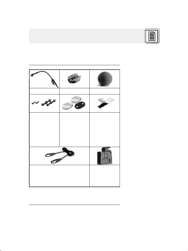
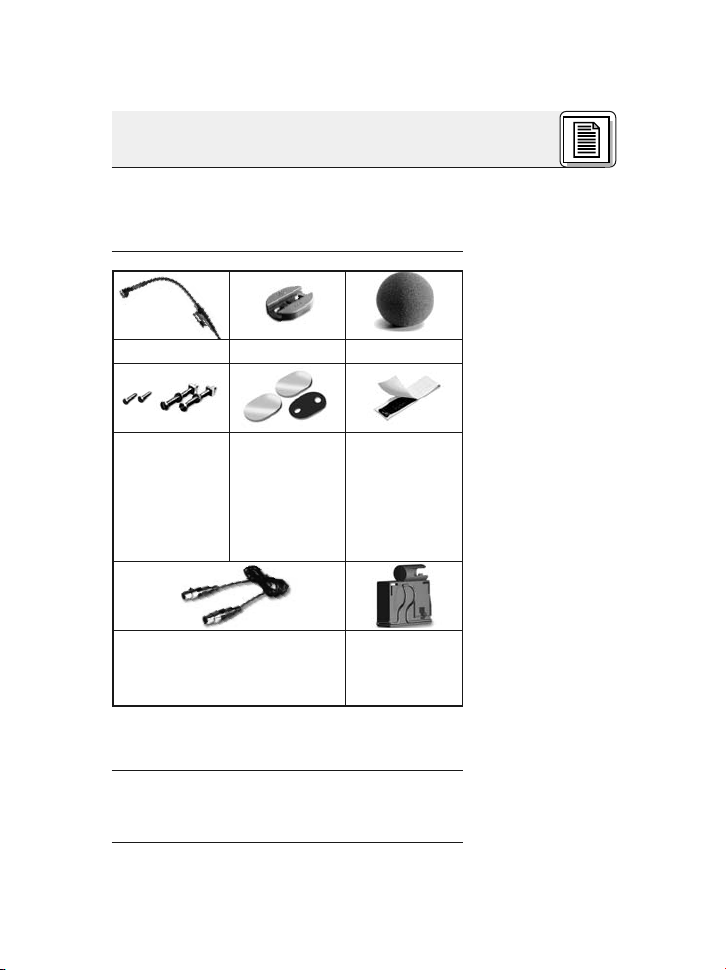
1xC516 1x H 516 1xW44
2 Stück Holzschrauben
(2,9 x 13 mm),
2 Stück Maschinenschrauben
(3 x 30 mm)
1 x Verbindungskabel MiniXLR/Mini-XLR, 1.5 m lang
Kontrollieren Sie bitte, ob die Verpackung alle
oben angeführten Teile enthält. Falls etwas fehlt,
wenden Sie sich bitte an Ihren AKG-Händler.
3 Stück Gummiplättchen:
2 x klebebeschichtet, 1 x
mit Öffnungen
für Montageschrauben
Elastische
Klebemasse
1 x Adapter
A 400 für Taschensender PT
40 oder PT
400
1.1 Sicherheitshinweis
1.2 Lieferumfang
• Batteriespeisegerät B 29 L
• Weiteres Zubehör siehe www.akg.com oder
aktuelle MicroMic-Broschüre.
1.3 Optionales
Zubehör
3AKG C 516 ML
Page 4

1 Beschreibung
1.4 Kurz-
beschreibung
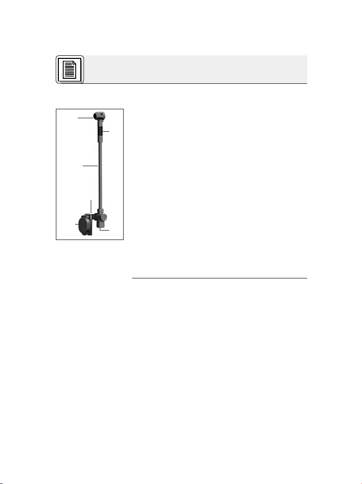
Abb. 1: Mikrofon
C 516 ML
1 Mikrofon mit nierenförmiger Richtcharakteristik
für hohe Rückkopplungssicherheit. Frequenzgang speziell für Akkordeon, Gitarren/Bassverstärker und Klavier ausgelegt.
2 Elastische Lagerung zur wirkungsvollen Unter-
drückung mechanischer Störgeräusche
3 Schwanenhals (125 mm) zur exakten Positio-
nierung des Mikrofons.
4 Mini-XLR-Ausgangsbuchse für Anschlusska-
bel
5 Trägerplatte für Adapter A 400 zum Befestigen
des Taschensenders PT 40 oder PT 400
6 Montageplättchen H 516 zum Befestigen des
Mikrofons am Instrument oder Lautsprecher
• Für Speisung mittels Batteriespeisegerät
B 29 L, Phantomspeiseadapter MPA V L oder
Taschensender PT 40, PT 400.
• 1,5 m langes, steckbares Anschlusskabel mit
3-poligem Mini-XLR-Stecker.
• Adapter A 400 zum Befestigen des Taschensenders PT 40 oder PT 400
4
AKG C 516 ML
Page 5
2 Anschluss
Das C 516 ML ist ein Kondensatormikrofon und
benötigt daher eine Stromversorgung.
Wenn Sie andere als die von AKG empfohlenen
Speisegeräte verwenden, kann das Mikrofon
beschädigt werden und erlischt die Garantie.
1. Verbinden Sie mittels des mitgelieferten Anschlusskabel die Ausgangsbuchse (5) am
Schwanenhals mit einer der beiden Mini-XLRBuchsen am B 29 L oder der Mini-XLRKupplung am Anschlusskabel des MPA V L.
Der Stecker verriegelt sich automatisch.
• Zum Abziehen des Kabels drücken Sie auf den
Entriegelungsknopf am Mini XLR-Stecker und
ziehen Sie den Stecker aus der Buchse heraus.
• Um das Kabel nicht zu beschädigen, zie-
hen Sie niemals am Kabel selbst!
2. B29L:Verbinden Sie das B 29 L mit dem ge-
wünschten Eingang.
MPA V L: Stecken Sie den MPAVLaneinen
symmetrischen XLR-Mikrofoneingang mit
Phantomspeisung an und schalten Sie die
Phantomspeisung ein.
• Verbinden Sie mittels des mitgelieferten Anschlusskabel die Ausgangsbuchse am Schwanenhals mit der Eingangsbuchse am Taschensender.
2.1 Einleitung
Wichtig!
2.2B29L
oder MPA V L
Kabel abziehen:
Wichtig!
2.3 Anschluss an
Taschensender
• Sie können den Taschensender am Gürtel oder
am Instrument befestigen. Die Taschensender
PT 40 und PT 400 können Sie auch direkt am
Mikrofon befestigen.
Hinweis:
Siehe Kapitel 2.3.1
auf Seite 6.
5AKG C 516 ML
Page 6

2 Anschluss
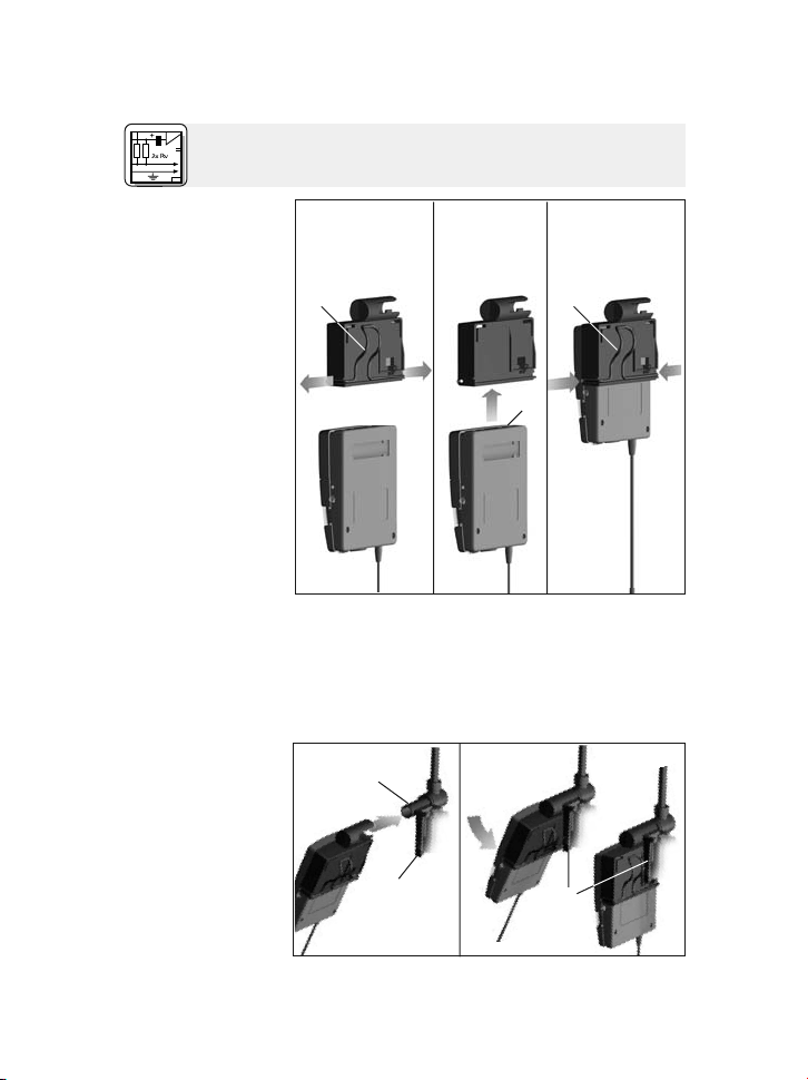
2.3.1 Taschensen-
der am Mikrofon
befestigen
Abb. 2: Taschen-
sender am Adapter
befestigen
Siehe Abb. 2.
321
1. Ziehen Sie die Enden des Haltebügels (1) aus
dem Adapter heraus.
2. Schieben Sie den Taschensender (2) bis zum
Anschlag in den Adapter hinein.
3. SteckenSie die Enden des Haltebügels (1) wieder in die Öffnungen im Adapter. Die Enden
4
5
Abb. 3: Adapter
mit Taschensender
am Mikrofon be-
festigen
6
AKG C 516 ML
Page 7
2 Anschluss
des Haltebügels greifen in die Öffnungen im
Gehäuse des Taschensenders ein und fixieren
den Taschensender.
4. Schieben Sie den Adapter mit dem Taschensender auf den Dorn (3) an der Trägerplatte (4).
5. Drücken Sie den Adapter auf die Trägerplatte
(4). Der Adapter rastet hörbar ein.
6
Siehe Abb. 3
auf Seite 6.
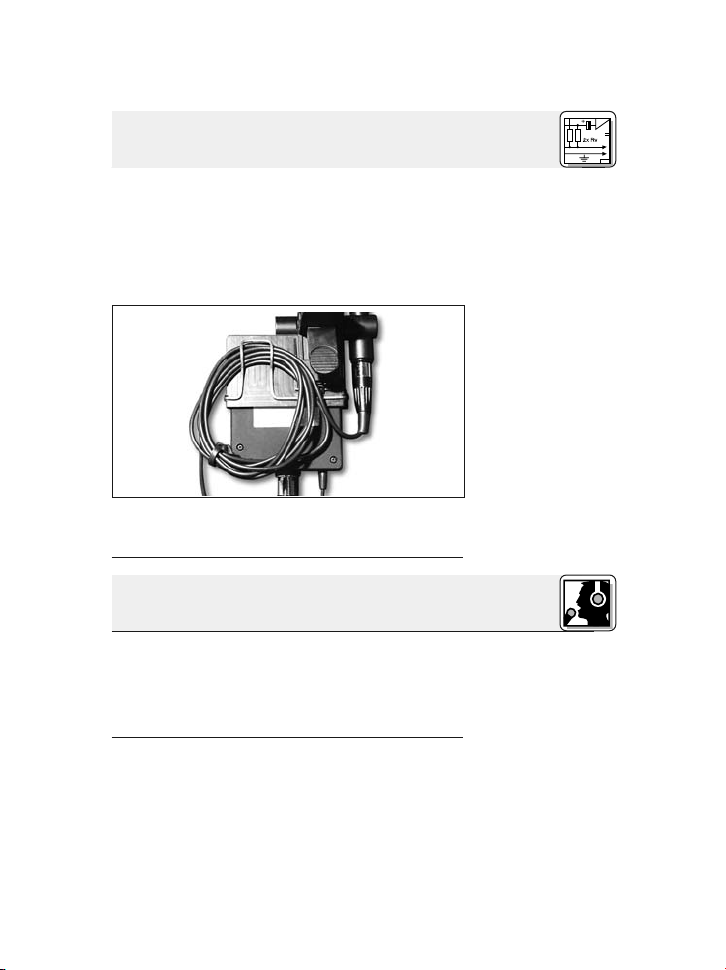
Abb. 4: Anschlusskabel aufrollen und
fixieren
6. Rollen Sie das Anschlusskabel auf und fixieren
Sie es unter dem Haltebügel.
3 Anwendung
Bevor Sie das Mikrofon endgültig am Instrument
oder der Lautsprecherbox befestigen, testen Sie
das Mikrofon an verschiedenen Stellen, um den
besten Sound zu finden. Befestigen Sie das Mikrofon dazu provisorisch mit der mitgelieferten
Klebemasse.
Schritt 1: Befestigen Sie das Montageplättchen
H 516 am Instrument oder der Lautsprecherbox (siehe a, b oder c).
Siehe Abb. 4.
3.1 Einleitung
Weitere Anwendungshinweise finden Sie in Kapitel
3.3 bis 3.5.
3.2 Mikrofon befestigen
7AKG C 516 ML
Page 8
3 Anwendung
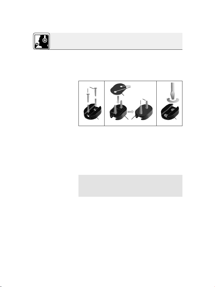
a) Befestigung
mittels
Schrauben:
Abb. 5: Unterlegen
des Gummiplätt-
chens zur Dämp-
fung mechanischer
Störgeräusche
Siehe Abb. 5.
Wichtig!
b) Befestigung
ohne Schrauben
an ebenen Flä-
chen bzw. ...
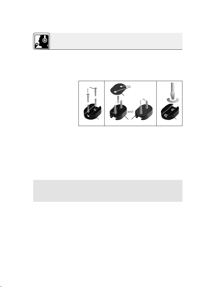
1. Verwenden Sie, je nach Wandstärke und Material desGehäuses, die mitgelieferten 13 mm langen Holzschrauben oder die 30 mm langen Maschinenschrauben mit Kontermutter.
23 4
2. Stecken Sie die Schrauben (1) durch die Öffnungen im Montageplättchen (2).
3. Legen Sie das nichtklebende Gummiplättchen
(3) so auf das Montageplättchen (2), dass die
Schrauben (1) in die Öffnungen (4) im Gummiplättchen (3) eingreifen.
4. Schrauben Sie das Montageplättchen (2) am
Instrument bzw. Lautsprecher an.
• Um die körperschalldämpfende Wirkung des
Gummiplättchens zu erhalten, ziehen Sie die
Schrauben nur soweit an, dass das Gummiplättchen nicht zusammengedrückt wird.
• Ziehen Sie das Abdeckpapier von beiden Seiten des Gummiplättchens ab und drücken Sie
das Gummiplättchen fest an das H 516 und an
das Instrument oder die Lautsprecherbox.
c) an unebenen
Flächen:
8
• Verwenden Sie anstelle des Gummiplättchens
die mitgelieferte Klebemasse.
AKG C 516 ML
Page 9
3 Anwendung
• Die Körperschallkompensation ist in beiden
Fällen (b und c) gleich wie bei der Befestigung
mittels Schrauben.
Schritt 2: Schieben Sie die Trägerplatte des Mi-
krofons in das Montageplättchen H516 ein, bis
die Trägerplatte hörbar einrastet.
• Sie können das Mikrofon jederzeit abmontieren, um es z.B. vor Schäden beim Transport zu
schützen. Ziehen Sie dazu das Mikrofon aus
dem Montageplättchen H 516 heraus.
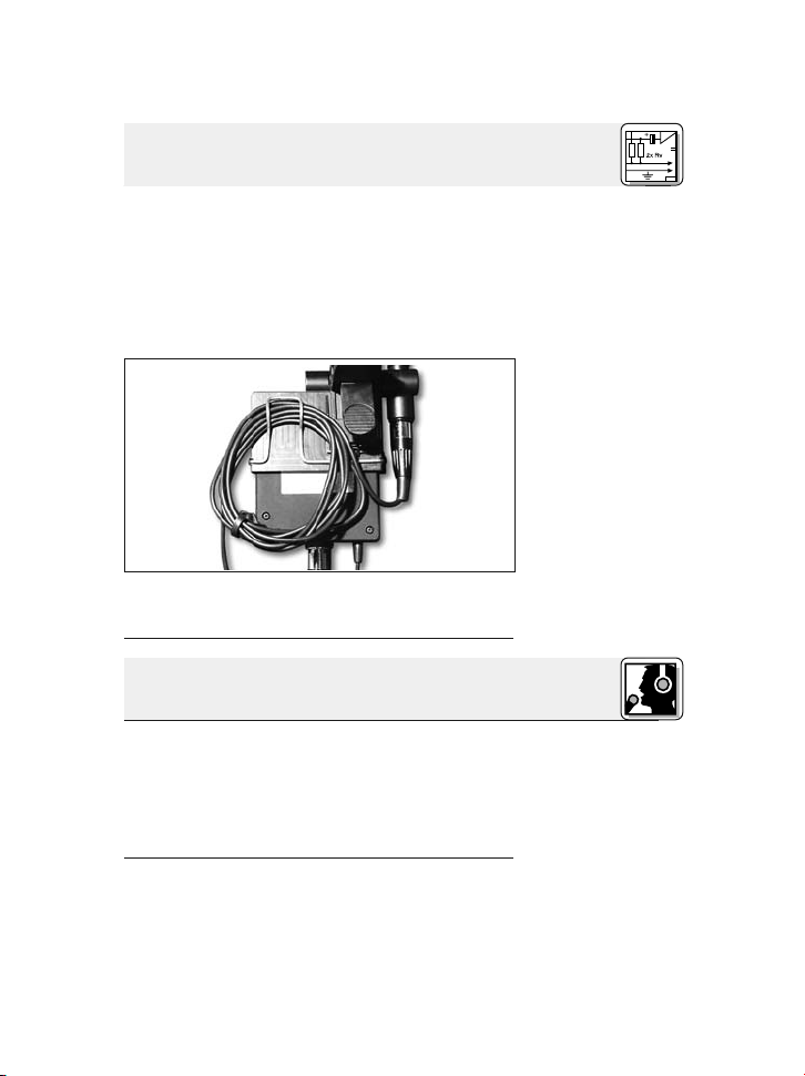
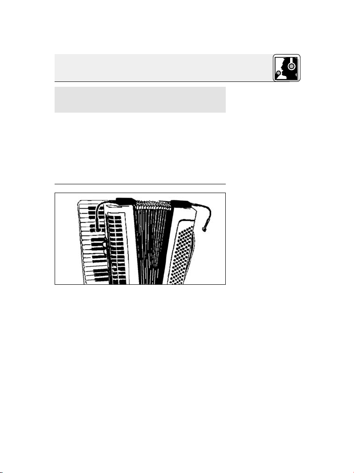
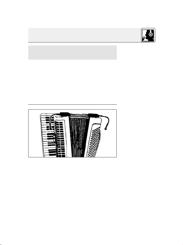
Zur optimalen Abnahme des Akkordeons benötigen Siezwei Mikrofone, eines für denBassbereich
und eines für den Diskant. Mit dem Schwanenhals
können Sie das Mikrofon genau auf das Instrument ausrichten.
Bei größeren Instrumenten können Sie das Mikrofon auch unter der Verschalung des Akkordeons
einbauen. Wir empfehlen, in diesem Fall den mitgelieferten Windschutz W 44 zur Unterdrückung
von Blasgeräuschen des Blasebalgs auf das Mikrofon zu stecken.
Führen Sie die Kabel der beiden Mikrofone entlang der Trägerriemen am Rücken zusammen und
von dort zum Batteriespeisegerät B 29 L oder den
Hinweis:
3.3 Akkordeon
Abb. 6: Akkordeonabnahme mit zwei
C 516 ML
Siehe Abb. 6.
9AKG C 516 ML
Page 10
3 Anwendung
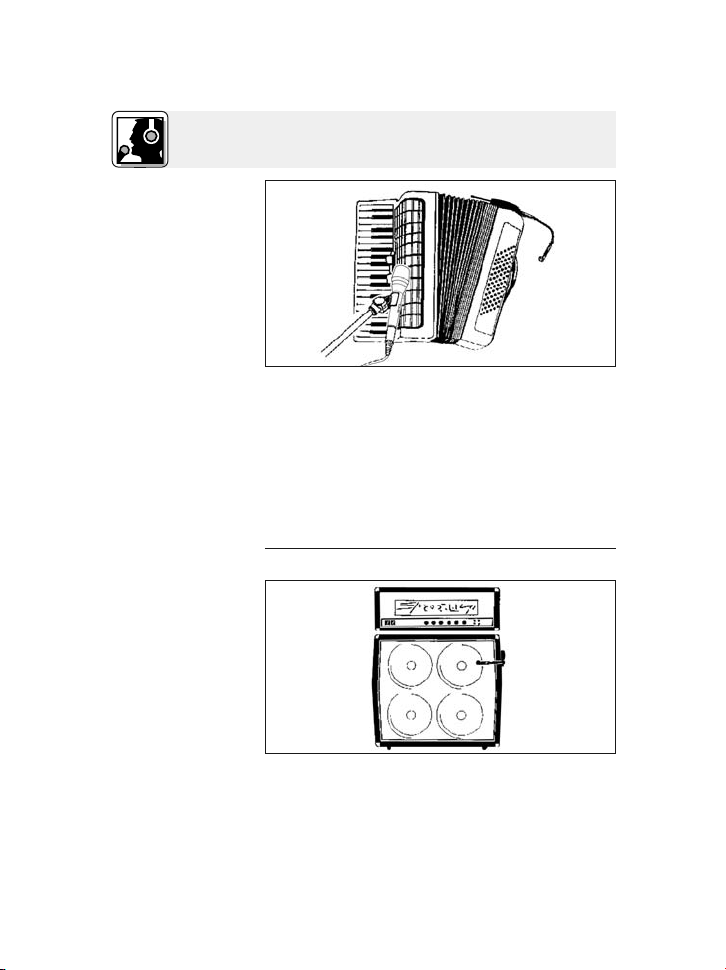
Abb. 7: Akkordeon-
abnahme mit
C 516 ML und sta-
tivgebundenem
Mikrofon
Taschensendern, damit die Kabel beim Spielen
nicht stören.
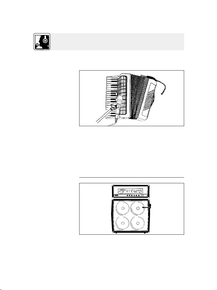
Siehe Abb. 7.
3.4 Gitarren-,
Bassverstärker-
box, Leslie
Abb. 8:
Gitarren/
Bassverstärker
Siehe Abb. 8.
10
Sie können das Akkordeon auch mit einem
C 516 ML und einem stativgebundenen Mikrofon
abnehmen:
1. Befestigen Sie das C 516 ML auf der Bassseite
des Akkordeons und richten Sie das Mikrofon
auf eines der Schalllöcher aus.
2. Richten Sie das stativgebundene Mikrofon auf
die Diskantseite des Akkordeons aus.
Positionieren Sie das Mikrofon außerhalb des
Zentrums eines Lautsprechers, um den Verstärkersound unverfälscht zu übertragen. Wenn Sie das
AKG C 516 ML
Page 11
3 Anwendung
Mikrofon direkt auf das Zentrumdes Lautsprechers
ausrichten, kann der Sound zu scharf werden.
Für die Abnahme von Mehrwegboxen und Leslies
empfehlen wir, zwei Mikrofone zu verwenden, eines für den Hoch- und Mitteltonlautsprecher und
eines für den Bassbereich.
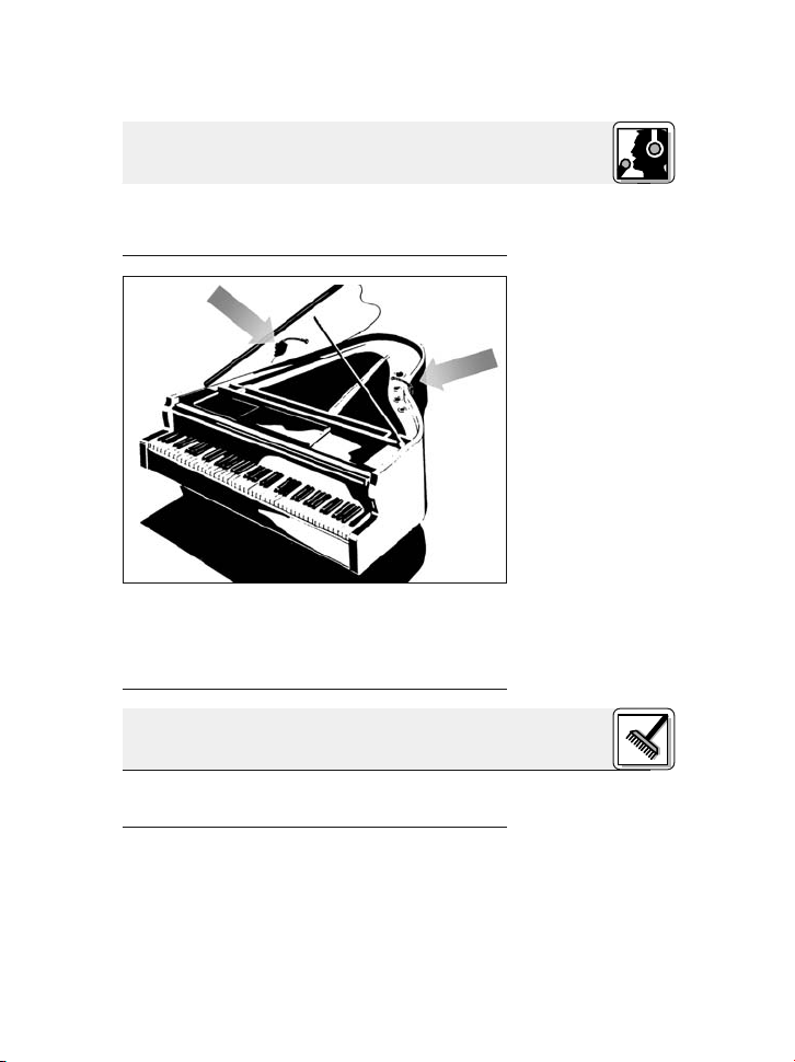
3.5 Flügel
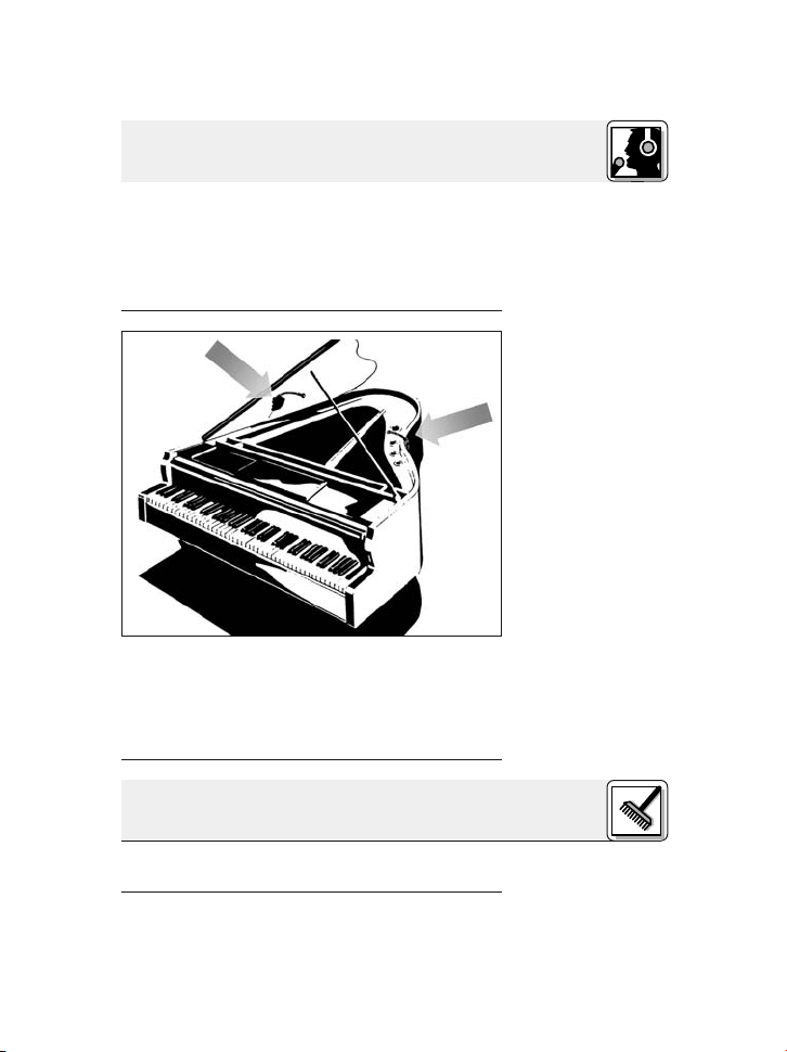
Abb. 9: Abnahme
des Flügels mit
zwei C 516 ML
Auf Grund der sehr großen Abstrahlfläche des
Klaviers empfehlenwir, zwei Mikrofone zuverwenden, um ein neutrales Klangbild zu erreichen.
Richten Sie ein Mikrofon auf den Bassbereich und
das zweite auf die mittleren und hohen Saiten aus.
4 Reinigung
Reinigen Sie das Gehäuse des Mikrofons mit einem mit Wasser befeuchteten Tuch.
Siehe Abb. 9.
11AKG C 516 ML
Page 12
5 Fehlerbehebung
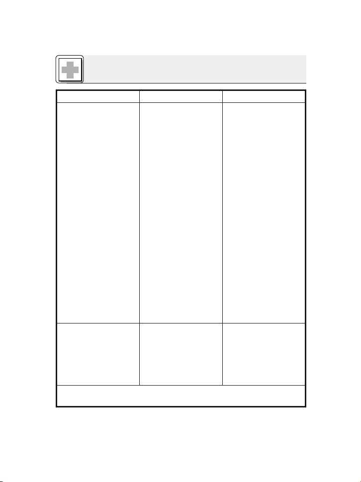
Fehler Mögliche Ursache Abhilfe
Kein Ton: 1. Mischpult und/oder
Verstärker ausgeschaltet.
2. Kanal-Fader oder
Summenpegelregler
am Mischpult oder
Lautstärkeregler des
Verstärkers steht auf
Null.
3. Mikrofon nicht an
Mischpult oder
Verstärker angeschlossen.
4. Kabelstecker nicht
richtig angesteckt.
5. Kabel defekt.
6. Keine Speisespannung.
Verzerrungen: 1. Gain-Regler am
Mischpult zu weit
aufgedreht.
2. Mischpulteingang zu
empfindlich.
1. Mischpult und/oder
Verstärker einschalten.
2. Kanal-Fader oder
Summenpegelregler
am Mischpult oder
Lautstärkeregler des
Verstärkers auf gewünschten Pegel einstellen.
3. Mikrofon an Mischpult oder Verstärker
anschließen.
4. Kabelstecker nochmals anstecken.
5. Kabel überprüfen und
falls nötig ersetzen.
6. Phantomspeisung
einschalten.
Phantomspeisegerät:
ans Netz anschließen
bzw. Batterie(n) einlegen.
Kabel überprüfen und
falls nötig ersetzen.
1. Gain-Regler zurückdrehen.
2. 10-dB-Vorabschwächung zwischen Mikrofonkabel und Eingang stecken.
Siehe auch Bedienungsanleitung des Senders und Empfängers!
12
AKG C 516 ML
Page 13
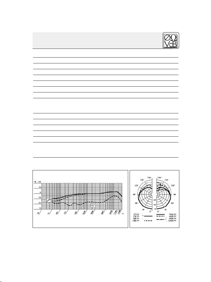
6 Technische Daten
Arbeitsweise: Kondensatorwandler mit Permanentladung
Richtcharakteristik: Niere
Übertragungsbereich: 60 – 20.000 Hz
Empfindlichkeit: 5 mV/Pa (-46 dBV bez. auf 1 V/Pa)
Elektrische Impedanz bei 1000 Hz: ≤ 200 Ohm
Empfohlene Lastimpedanz: ≥ 2000 Ohm
Grenzschalldruck für 1 %/3 % Klirrfaktor: 130 dB/132 dB
Äquivalentschalldruckpegel: 31 dB(A) nach DIN 45412
Speisespannung: Batteriespeisegerät B 29 L, Phantomspei-
Kabellänge / Steckerart: 1,5 m / Mini-XLR 3-polig
Oberfläche: mattschwarz
Abmessungen (nur Mikrofon): Länge: 235 mm, max. Breite: 47 mm
Nettogewicht (Mikrofon inkl. Kabel): 46 g
Bruttogewicht: 390 g
Dieses Produkt entspricht den in der Konformitätserklärung angeführten Nor-
men. Sie können die Konformitätserklärung auf http://www.akg.com oder per EMail an sales@akg.com anfordern.
Frequenzgang Polardiagramm
seadapter MPA V L, AKG WMS Taschensender
13AKG C 516 ML
Page 14

Table of Contents
Page
1 Precaution/Description ...........................15
1.1 Precaution..................................15
1.2 Unpacking..................................15
1.3 Optional Accessories .........................15
1.4 Brief Description .............................16
2 Interfacing ......................................17
2.1 Introduction.................................17
2.2B29LorMPAVL............................17
2.3 Connecting to a Bodypack Transmitter............17
2.3.1 Attaching the Transmitter to the Microphone ...18
3 Using Your Microphone ...........................19
3.1 Introduction.................................19
3.2 Mounting the Microphone......................19
3.3 Accordion ..................................21
3.4 Guitar/Bass Amp Speaker, Leslie Cabinet .........22
3.5GrandPiano ................................23
4 Cleaning........................................23
5 Troubleshooting .................................24
6 Specifications ...................................25
14
AKG C 516 ML
Page 15
1 Precaution/Description
Please make sure that the piece of equipment
your microphone will be connected to fulfills the
safety regulations in force in your country and is
fitted with a ground lead.
1xC516 1x H 516 1xW44
2 wood screws
(2,9 x 13 mm),
2 machine
screws
(3 x 30 mm)
1 x mini XLR to mini XLR connecting cable (5 ft./1.5 m)
Check that the packaging contains all of the components listed above. Should anything be missing, please contact your AKG dealer.
2 double-sided
adhesive rubber plates, 1
rubber plate
with locating
holes
Elastic adhesive compound
1 x A 400 adapter for PT 40 or
PT 400 bodypack transmitter
1.1 Precaution
1.2 Unpacking
• B 29 L battery power supply
• For more accessories, visit www.akg.com or
refer to the latest MicroMic brochure.
1.3 Optional Accessories
15AKG C 516 ML
Page 16
1 Description
1.4 Brief
Description
Fig. 1: C 516 ML
microphone.
1 Cardioid microphone for high gain before feed-
back. Frequency response tailored to accordion, guitar/bass amp, and piano miking.
2 Shock mount reduces handling and cable
noise.
3 125-mm (5-in.) gooseneck for accurate micro-
phone alignment.
4 Mini XLR output socket for connecting cable.
5 Mounting plate for the A 400 adapter allowing
you to attach a PT 40 or PT 400 bodypack
transmitter.
6 H 516 installationplate for mounting the micro-
phone on an instrument or speaker.
• For use with the B 29 L battery power supply,
MPAVLphantompoweradapter, or PT 40 or
PT 400 bodypack transmitters.
• 5-ft. (1.5-m) plug-in connecting cable with 3pin mini XLR connectors.
• A 400 adapter for attaching a PT 40 or PT 400
bodypack transmitter.
16
AKG C 516 ML
Page 17
2 Interfacing
The C 516 ML is a condenser microphone and
therefore needs a power supply.
Using any power supply other than those
recommended by AKG may damage your
microphone and will void the warranty.
1. Use the supplied connecting cable to connect
the output socket (4) on the gooseneck to one
of the two mini XLR sockets on the B 29 L or
the mini XLR socketon the connecting cable of
the MPA V L.
The connector will lock automatically.
• To disconnect the cable, press the unlocking
button on the mini XLR connector (1) and pull
the connector (1) out of the socket.
• To avoid damaging the cable, never pull
at the cable itself!
2. B29L:Connectthe B 29 L tothe desired input.
MPA V L: ConnecttheMPAVLtoabalanced
XLR microphone input with phantom power
and switch the phantom power on.
• Use the supplied connecting cable to connect
the output socket on the gooseneck to the input socket on the bodypack transmitter.
•
You can attach the bodypack transmitter to your
belt or to the instrument. The PT 40 and PT 400
bodypack transmitters will also mount directly on
the microphone.
2.1 Introduction
Important!
2.2B29L
or MPA V L
Disconnecting
the cable:
Important!
2.3 Connecting
to a Bodypack
Transmitter
Note:
Refer to section
2.3.1 on page 18.
17AKG C 516 ML
Page 18
2 Interfacing
2.3.1 Attaching
the Bodypack
Transmitter to the
Microphone
Fig. 2: Inserting the
transmitter into the
adapter.
Refer to fig. 2.
321
1. Pull the ends of the fixing clip (1) out of the
adapter.
2. Slide the transmitter (2) all the way into the
adapter.
3. Reinsert the ends of the fixing clip (1) into the
openings in the adapter. The ends of the fixing
4
5
Fig. 3: Mounting
the adapter and
transmitter on the
microphone.
18
AKG C 516 ML
Page 19
2 Interfacing
clip engage the locating holes in the transmit-
ter case to hold the transmitter in place.
4. Slide the adapter with the transmitter on the
shaft (3) on the mounting plate (4).
5. Press the adapter against the mounting plate
(4). The adapter will lock with an audible click.
6
Refer to fig. 3
on page 18.
Fig. 4: Coiling and
stowing the connecting cable.
6. Coil the connecting cable and tuck it under the
fixing clip.
3 Using Your Microphone
Before permanently mounting the microphone on
your instrument or speaker cabinet, experiment
with various microphone positions to get the best
possible sound. Fix the microphone temporarily
using the supplied adhesive putty.
Step 1: Fix the H 516 installation plate on your instrument or speaker cabinet (see a, b, or c below).
Refer to fig. 4.
3.1 Introduction
For more application hints refer to
sections 3.3 to 3.5.
3.2 Mounting
the Microphone
19AKG C 516 ML
Page 20
3 Using Your Microphone
a) Using screws:
Fig. 5: Inserting the
rubber plate to
reduce mechanical
noise.
Refer to fig. 5.
Important!
b) Mounting the
microphone with
no screws on a
flat surface or...
1. Depending on the material and thicknessof the
installation surface, use the 13-mm (0.5-in.)
wood screws or the 30-mm (1.2-in.) machine
screws and nuts.
23 4
2. Insert the screws (1) into the openings in the installation plate (2).
3. Place the non-adhesive rubber plate (3) on the
installation plate (2), making the screws engage
the locating holes (4) in the rubber plate (3).
4. Screw the installation plate (2) on the instrument or speaker.
• To maintain the mechanical-noise attenuation of the rubber plate, do not tighten the
screws hard enough to squeeze the rubber
plate.
• Remove the backing paper from both sides of
the rubber plate and press the rubber plate
firmly on the bracket and then on the instrument or speaker.
c) on an uneven
surface:
20
• Use the supplied adhesive putty instead of the
rubber plate.
AKG C 516 ML
Page 21
3 Using Your Microphone
• Both the rubber plate and the elastic putty provide the same amount of mechanical noise attenuation as the rubber eyelets on the H 516.
Step 2: Slide the mounting plate (1) of the microphone into the H 516 installation plate (2) to the
point that the mounting plate (1)audibly clicks into
place.
• You can remove the microphone easily, for instance, in order to prevent it being damaged
during shipping: pull the microphone out of the
H 516 mounting plate.
To mic up an accordion optimally, you will need
two microphones, onefor the bass and one for the
treble range. The gooseneck lets you align each
microphone exactly as desired.
If your instrument is big enough, you can even install the microphone inside the case, making sure
to slip on the supplied W 44 windscreen to suppress the wind noise produced by the bellows.
To keep the microphone cables out of your way,
route them along the straps and from there to a
B 29 L or two bodypack transmitters.
Note:
3.3 Accordion
Fig. 6:Miking up an
accordion with two
C 516 MLs.
Refer to fig. 6.
21AKG C 516 ML
Page 22
3 Using Your Microphone
Fig. 7: Miking up
an accordion with
a C 516 ML and a
stand-mounted
microphone.
Refer to fig. 7.
3.4 Guitar/Bass
Amp Speaker,
Leslie Cabinet
Alternatively, you can mic up the accordion with a
single C 516 ML and a stand-mounted microphone:
1. Mount the C 516 ML onthe bass side of theaccordion and point the microphone to one of the
sound holes.
2. Align the stand-mounted microphone with the
treble side of the accordion.
Fig. 8: Guitar/bass
amp.
Refer to fig. 8.
22
Place the microphone a little off the center of one
of the speakers in order to accurately capture the
sound ofthe amp. Pointingthe microphone directly at the center of the speaker may produce an exceedingly harsh sound.
AKG C 516 ML
Page 23
3 Using your Microphone
To mic up two or three-way speakers and Leslie
cabinets, use two microphones, one for the high
and midrange driver and one for the bass driver.
3.5 Grand Piano
Fig. 9: Miking up a
grand piano with
two C 516 MLs
The piano being a very large sound source, you
should use two microphones in order to get a neutral sound.
Aim one at the bass and one at the treble strings.
4 Cleaning
To clean the microphone case, use a soft cloth
moistened with water.
Refer to fig. 9.
23AKG C 516 ML
Page 24

5 Troubleshooting
Problem
No sound: 1. Power to mixer
Distortion: 1. Gain control onthe
Possible Cause Remedy
and/or amplifier is off.
2. Channel or master
fader on mixer, or volume control on amplifier is at zero.
3. Microphone is not
connected to mixer
or amplifier.
4. Cable connectors are
seated loosely.
5. Cable is defective.
6. No supply voltage.
mixer set too high.
2. Mixer input sensitivity
too high.
1. Switch power to
mixer or amplifier on.
2. Set channel or master fader on mixer or
volume control on
amplifier to desired
level.
3. Connect microphone
to mixer or amplifier.
4. Check cable connectors for secure seat.
Check cable and re-
5.
place if damaged.
6. Switch phantom
power on.
Phantom power supply: connect to power
outlet or insert battery
(batteries).
Check cable and replace if necessary.
1. Turn gain control
down CCW.
2. Connect a 10-dB
preattenuation pad
between microphone
cable and input.
24
Also read the transmitter and receiver manuals!
AKG C 516 ML
Page 25

6 Specifications
Type: pre-polarized condenser microphone
Polar pattern: cardioid
Frequency range: 60 Hz to 20,000 Hz
Sensitivity at 1 kHz: 5 mV/Pa (-46 dBV re 1 V/Pa)
Impedance: ≤ 200 ohms
Recommended load impedance: ≥ 2000 ohms
Max. SPL for 1%/3% THD: 130/132 dB SPL
Equivalent noise level: 31 dB(A) to DIN 45412
Power requirement:
Cable length / Connector: 1.5 m (5 ft.) / 3-pin mini XLR
Finish: matte black
Size (microphone only): length: 235 mm (9.3 in.)
Net weight (microphone and cable): 46 g (1.6 oz.)
Shipping weight: 320 g (11.3 oz.)
This product conforms to the standards listed in the Declaration of Conformity.
To order a free copy of the Declaration of Conformity, visit http://www.akg.com or
contact sales@akg.com.
Frequency Response Polar Diagram
B 29 L battery power supply,
MPA V L phantom adapter,
AKG WMS bodypack transmitters
max. width: 47 mm (1.9 in.)
25AKG C 516 ML
Page 26

Table des matières
Page
1 Consigne de sécurité / Description ..................27
1.1 Consigne de sécurité .........................27
1.2Fournitures.................................27
1.3 Accessoires opcionnels .......................27
1.4 Description succincte .........................28
2 Raccordement...................................29
2.1 Introduction.................................29
2.2B29LouMPAVL............................29
2.3 Raccordement à un émetteur de poche ...........29
2.3.1 Comment fixer l’émetteur de poche sur le microphone
3 Utilisation.......................................31
3.1 Introduction.................................31
3.2 Fixation du microphone .......................31
3.3 Accordéon .................................33
3.4 Enceintes de guitare et de basse, Leslie ...........34
3.5Pianoàqueue...............................35
4 Nettoyage ......................................35
5 Dépannage .....................................36
6 Caractéristiques techniques .......................37
.30
26
AKG C 516 ML
Page 27

1 Consigne de sécurité / Description
Vérifiez si l’appareil auquel vous voulez raccorder
le microphone répond aux prescriptions relatives
à la sécurité en vigueur et s’il possède une mise à
la terre de sécurité.
1xC516 1x H 516 1xW44
2 vis à bois
(2,9 x 13 mm),
2 vis d’assemblage
(3 x 30 mm)
1 câble de liaison mini-XLR/miniXLR, 1,5 m de long
Contrôlez si le carton contient bien tous les éléments énumérés ci-dessus. Si ce n’est pas le cas,
veuillez contacter votre distributeur AKG.
3 plaquettes de
caoutchouc : 2
avec surface
adhésive, 1 avec
trous pour vis de
montage
mastic
élastique
1 Adaptateur
A 400 pour émetteur de poche PT
40 ou PT 400
1.1 Consigne de
sécurité
1.2 Fournitures
• Alimentation batterie B 29 L
• Pour les autres accessoires voir www.akg.com
ou la brochure MicroMic la plus récente.
1.3 Accessoires
optionnels
27AKG C 516 ML
Page 28

1 Description
1.4 Description
succincte
Fig. 1 : Microphone
C 516 ML
1 Microphone à caractéristique cardioïde pour
une haute protection contre le larsen. Réponse
en fréquence spécialement adaptée pour l’accordéon, les amplificateurs de guitare et de
basse et le piano.
2 Suspension élastique pour suppression efficace
des bruits mécaniques
3 Col-de-cygne de 125 mm permettant de posi-
tionner le micro avec une grande précision.
4 Prise mini-XLR pour câble de raccordement
5 Plaque support pour adaptateur A 400 permet-
tant de fixer l’émetteur de poche PT 40 ou
PT 400
6 Plaquette de montage H 516 pour fixer le mi-
crophone à l’instrument ou au haut-parleur
• Pour alimentation par boîtier à pile B 29 L, module d’alimentation fantôme MPA V L ou émetteur de poche PT 40 ou PT 400.
• Câble de raccordement enfichablede 1,5m de
long, avec connecteur mini-XLR 3 points.
• Adaptateur A 400 pour la fixation de l’émetteur
de poche PT 40 ou PT 400
28
AKG C 516 ML
Page 29

2 Raccordement
Le C 516 ML est un microphone électrostatique ;
il a donc besoin d’une alimentation.
L’utilisation d’alimentations autres que
celles recommandées par AKG peut provoquer des dégâts sur le micro et entraîne la
perte de la garantie.
1. A l’aide du câble de raccordement fourni,
connectez la prise de sortie (5) du col-decygne sur une des deux prises mini-XLR du
B 29 L ou sur le connecteur mini-XLR femelle
du câble de raccordement du MPA V L.
Le connecteur se verrouille automatiquement.
• Pour détacher le câble, appuyez sur le bouton
de déverrouillage du connecteur mini-XLR (1)
et sortez le connecteur de la prise.
• Pour ne pas risquer d’abîmer le câble, ne
sortez jamais le connecteur en tirant sur
le câble.
2. B29L:Raccordez le B 29 L sur l’entrée voulue.
MPAVL:Connectez le MPAVLsuruneentrée
de micro symétrique type XLR avec alimentation fantôme et mettez l’alimentation fantôme
sous tension.
• A l’aide du câble de raccordement fourni,
connectez la prise de sortie du col-de-cygne
sur la prise d’entrée de l’émetteur de poche.
2.1 Introduction
Important!
2.2B29Lou
MPAVL
Débrancher le
câble :
Important!
2.3 Raccordement à un émetteur de poche
• Vous pouvez fixer l’émetteur de poche à votre
ceinture ou à l’instrument. Les émetteurs de
poche PT 40 et PT 400 peuvent également être
fixés directement sur le micro.
Remarque :
Voir point 2.3.1,
page 30.
29AKG C 516 ML
Page 30

2 Raccordement
2.3.1 Comment
fixer l’émetteur
de poche sur le
microphone
Fig. 2 : Comment
fixer l’émetteur
de poche sur
l’adaptateur
Voir Fig. 2.
321
1. Extrayez les extrémités de l’étrier (1) de l’adaptateur.
2. Enfoncez l’émetteur de poche (2) dans l’adaptateur jusqu’en butée.
3. Réintroduisez les extrémités de l’étrier (1) dans
les trous de l’adaptateur. Les extrémités de
4
5
Fig. 3 : Comment
fixer l’adaptateur
avec l’émetteur de
poche sur le
microphone
30
AKG C 516 ML
Page 31

2 Raccordement
l’étrier s’enclenchent dans les ouvertures du
boîtier de l’émetteur qui se trouve ainsi fixé.
4. Glissez l’adaptateur avec l’émetteur de poche
sur l’ergot (3) de la plaque support (4).
5. Pressez l’adaptateur contre la plaque support
(4). L’enclenchement est audible.
6
Voir Fig. 3,
page 30.
Fig. 4 : Enrouler et
fixer le câble de
raccordement
6. Enroulez le câble de raccordement et fixez-le
sous l’étrier.
3 Utilisation
Avant de fixer le microphone définitivement sur un
instrument ou une enceinte, faites des essais en
changeant le micro de place pour trouver la position donnant le meilleur son. Pour ce faire, fixez
provisoirement le micro avec le mastic fourni.
Etape 1 : Fixez la plaquette de montage H 516 sur
l’instrument ousur l’enceinte (voir a, b ou c ci-dessous).
1. Suivant l’épaisseur dela paroi et le matériau du
boîtier, utilisez les vis à bois de 13 mm de long
Voir Fig. 4.
3.1 Introduction
Voir aussi les
points 3.3 à 3.5
3.2 Fixation du
microphone
a) Fixation par vis :
31AKG C 516 ML
Page 32

3 Utilisation
ou les vis d’assemblage de 30 mm avec
contre-écrous.
Fig. 5: Mise en
place de la pla-
quette de caout-
chouc pour l’atté-
nuation des vibra-
tions mécaniques
Voir Fig. 5.
Important!
b) Fixation sans
vis sur une
surface plane
ou...
c) ... sur une sur-
face non plane :
Remarque :
32
23 4
2. Passez les vis (1) dans les trous de la plaquette
de montage (2).
3. Placez la plaquette de caoutchouc non adhésive (3) sur la plaquette de montage (2), de manière à ce que les vis (1) mordent dansles trous
(4) de la plaquette de caoutchouc (3).
4. Vissez la plaquette de montage (2) sur l’instrument ou le haut-parleur.
• Afin de conserver l’effet d’atténuation des
vibrations mécaniques de la plaquette de
caoutchouc, serrez les vis juste ce qu’il faut
pour ne pas comprimer la plaquette.
• Enlevez le papier recouvrant les deux faces de
la plaquette de caoutchouc et collez celle-ci
sur laH 516 etsur l’instrument oul’enceinte, en
pressant fortement.
• Utilisez le mastic fourni, à la place de la plaquette de caoutchouc.
• La compensation des bruits de structure est
dans les deux cas (b et c) la même que dans le
cas d’une fixation par vis.
AKG C 516 ML
Page 33

3 Utilisation
Etape 2 : Glissez la plaque support du micro (1)
dans laplaquette de montage H 516 (2) jusqu’à
enclenchement audible.
• Vous pouvez démonter le micro quand vous le
souhaitez, p.ex. pour éviter qu’il ne s’abîme
pendant le transport. A cet effet, extrayez le
micro de la plaquette de montage H 516.
3.3 Accordéon
Fig. 6 : Prise de
l’accordéon avec
deux C 516 ML
Pour une prise de son optimale sur l’accordéon,
on a besoin de deux micros: un pour le registre
des basses et un pour celui des aigus. Le col-decygne permet d’orienter le micro avec précision
par rapport à l’instrument.
Sur les gros accordéons, on peut aussi monter le
micro sous la coque; dans ce cas il est recommandé d’utiliser la bonnette antivent W 44 pour
atténuer les bruits de souffle provenant du soufflet.
Passez les câbles des micros le long de la bandoulière et faites-les partir du dos du musicien
vers l’alimenation à piles B 29 L ou les émetteurs
de poche, de manière à ne pas gêner l’accordéoniste.
Voir Fig. 6.
33AKG C 516 ML
Page 34

3 Utilisation
Fig. 7 : Prise de
l’accordéon avec
le C 516 ML et un
micro sur pied
Voir Fig. 7.
3.4 Enceintes de
guitareetde
basse, Leslie
Sur l’accordéon vous pouvez également effectuer
la prise de son avec un C 516 ML et un micro sur
pied:
1. Fixez le C 516 ML du côté du registre des
basses de l’accordéon et orientez le micro vers
un des évents
2. Orientez le micro sur pied vers le registre de
l’aigu de l’accordéon.
Enceinte de guitare
Fig. 8 :
et de basse
Voir Fig. 8.
34
Pour ne pas dénaturer le son, ne dirigez pas le micro sur le centre d’un haut-parleur. Lorsque le micro est orienté directement vers le centre du hautparleur le son risque d’être trop sec.
Pour la prise de son sur amplificateur à plusieurs
AKG C 516 ML
Page 35

3 Utilisation
voies et sur Leslie, on a avantage à utiliser deux
micros: un pour le haut-parleur aigu et médium et
un pour le grave.
3.5 Piano à queue
Fig.9:Prisedu
piano à queue avec
deux C 516 ML
Pour s’assurer d’une restitution neutre malgré
l’importance de la surface de diffusion du son
d’un piano, il convient d’utiliser deux micros.
Orientez l’un pour les graves et l’autre vers le registre des moyennes et hautes fréquences.
4 Nettoyage
Le boîtierdu micro se nettoie avecun chiffon légèrement humide (eau claire).
Voir fig. 9.
35AKG C 516 ML
Page 36

5 Dépannage
Problème
Pas de son : 1. La console demixage
Distorsions : ble de mixage est trop
Veuillez vous reporter aussi auxnotices d’emploide l’émetteur et du récepteur !
Cause possible Remède
et/ou l’amplificateur ne
sont pas sous tension.
2. Le fader ducanal ou le réglage de niveau master de la
console de mixage ou le
réglage de niveau sonore
de l’ampli est sur zéro.
3. Le micro n’est pas connecté à la console de mixage ou à l’ampli.
4. La fiche estmal enfoncée.
5. Le câble estabîmé.
6. Pas de tension d’alimentation.
1. Le réglage degain de la ta-
haut.
2. L’entrée de la table de mixage est trop sensible.
1. Mettre la console de mixage et/ou l’amplificateur
sous tension.
2. Régler le fader du canal ou
le réglage de niveau master de la console de mixage ou le réglage de niveau sonore de l’ampli sur
la valeur voulue.
3. Connecter le micro à la
console de mixage ou à
l’ampli.
4. Enfoncer la fichecorrectement.
5. Contrôler le câble et le
remplacer le cas échéant.
6. Mettre l’alimentation fantôme sous tension.
Appareil d’alimentation
fantôme : brancher sur le
secteur ou mettre une (des)
pile(s).
Contrôler le câble et le
remplacer le cas échéant.
1. Baisser le réglage de gain.
2. Insérer un pré-atténuateur
de sensibilité entre le câble
du micro et l’entrée.
36
AKG C 516 ML
Page 37

6 Caractéristiques techniques
Fonctionnement: microphone électrostatique à charge per-
Directivité: cardioïde
Réponse en fréquence: 60 … 20.000 Hz
Sensibilité : 5 mV/Pa (-46 dBV rapp. à 1 V/Pa)
Impédance électrique à 1.000 Hz: ≤ 200 ohms
Impédance de charge recommandée: ≥ 2000 ohms
Niveau maximum de pression sonore pour un facteur
de distorsion de 1% / 3%: 130 / 132 dB SPL
Niveau de bruit équivalent: 31 dB(A) selon DIN 45412
Tension d’alimentation: alimentation à piles B 29 L,
Longueur du câble / Connecteur: 1,5 m / type mini-XLR, 3 points
Couleur: noir mat
Dimensions (micro seulement): longueur : 235 mm, largeur maxi.: 47 mm
Poids net (micro et câble) : 55 g / 390 g
Poids brut : 320 g
Ce produit est conforme aux normes citées dansla Déclaration de Conformité,
dont vous pouvez prendre connaissance en consultant le site
http://www.akg.com ou en adressant une-mail à sales@akg.com.
manente
adaptateur fantôme MPA V L,
émetteurs de poche AKG WMS
Réponse en fréquence Diagramme polaire
37AKG C 516 ML
Page 38

Indice
Pagina
1 Indicazione per la sicurezza / Descrizione ............39
1.1 Indicazione per la sicurezza ....................39
1.2 In dotazione ................................39
1.3 Accessori opzionali...........................39
1.4 Breve descrizione ............................40
2 Collegamento ...................................41
2.1Introduzione ................................41
2.2B29LoMPAVL.............................41
2.3 Collegamento ad un trasmettitore da tasca ........41
2.3.1 Come fissare il trasmettitore sul microfono ....42
3 Impiego ........................................43
3.1Introduzione ................................43
3.2 Come fissare il microfono ......................43
3.3 Fisarmonica ................................45
3.4 Cassa di amplificazione per chitarra e basso, leslie . . 46
3.5 Pianoforte a coda ............................47
4 Pulizia..........................................47
5 Eliminazione di difetti .............................48
6 Dati tecnici......................................49
38
AKG C 516 ML
Page 39

1 Indicazione per la sicurezza / Descrizione
Controllate per favore se l’apparecchio che volete
collegare al microfono corrisponde alle norme di
sicurezza vigenti e se è dotato di una messa a
terra di sicurezza.
1xC516 1x H 516 1xW44
2 viti da legno
(2,9 x 13 mm),
2 bulloni
(3 x 30 mm)
1 cavo mini-XL/mini-XLR,
lungo 1,5 m
Controllate per favore se la confezione contiene
tutti i componenti di cui sopra. Se manca qualcosa rivolgetevi al vostro rivenditore AKG.
3 piastrine di
gomma: 2 con
strati adesivi, 1
con aperture
per le viti di
montaggio
massa adesiva
elastica
1 adattatore
A 400per trasmettitore da tasca
PT 40 o PT 400
1.1 Indicazione
per la sicurezza
1.2 In dotazione
• Alimentatore a batteria B 29 L
• Per altri accessori vedi www.akg.com o l’attuale depliant MicroMic.
1.3 Accessori
opzionali
39AKG C 516 ML
Page 40

1 Descrizione
1.4 Breve
descrizione
Fig. 1: Microfono
C 516 ML
1 Microfono a direttività cardioide per alta sicu-
rezza contro il feedback. Risposta in frequenza
ideata specialmente per fisarmonica, casse di
amplificazione per chitarra/basso, pianoforte.
2 Supporto elastico per efficiente soppressione
dei rumori meccanici disturbanti.
3 Collo di cigno lungo 125 mm per il posiziona-
mento esatto del microfono.
4 Presa mini-XLR per cavi di collegamento.
5 Piastra base per l’adattatore A 400 per fissare il
trasmettitore da tasca PT 40 o PT 400.
6 Piastrina di montaggio H 516 per fissare il mi-
crofono sullostrumento o sulla cassa acustica.
• Per alimentazione mediante alimentatore a
batterie B 29 L, adattatore per alimentazione
phantom MPA V L oppure trasmettitore da tasca PT 40 o PT 400.
• Cavo di collegamento lungo 1,5 m, innestabile,
con connettore mini-XLR a 3 poli.
• Adattatore A 400 per fissare il trasmettitore da
tasca PT 40 o PT 400.
40
AKG C 516 ML
Page 41

Il C 416
III
è un microfono a condensatore e ha
quindi bisogno di alimentazione.
2 Collegamento
2.1 Introduzione
Se usate alimentatori diversi da quelli raccomandati dall’AKG, il microfono può subire
danni e la garanzia si estingue.
1. Collegate la presa d’uscita (5) disposta sul
collo di cigno ad una delle due prese mini-XLR
disposte sul B 29 L o all’accoppiamento miniXLR disposto sul cavo di collegamento del
MPA V L, servendovi del cavo di collegamento
in dotazione.
• Per sfilare il cavo, premete il bottone di sblocco
sul connettore mini-XLR (1) e sfilate il connettore (1) dalla presa.
• Per non danneggiare il cavo, non esercitate mai trazione direttamente sul cavo!
2. B 29 L: Collegate il B 29 L (2) con l’ingresso
prescelto.
MPA V L: Collegate l’MPA V L a un ingresso microfonico XLR simmetrico con alimentazione
phantom e inserite l’alimentazione phantom.
• Collegate la presa d’uscita disposta sul collo di
cigno alla presa d’ingresso del trasmettitore da
tasca servendovi del cavo di collegamento in
dotazione.
Potete fissare il trasmettitore da tasca sulla cintura
o sullo strumento. I trasmettitori da tasca PT 40 e
PT 400 possono venir fissati anche direttamente
sul microfono.
Importante!
2.2B29Lo
MPAVL
Sfilare il cavo:
Importante!
2.3 Collegamento ad un trasmettitore da
tasca
Avvertenza:
vedi capitolo 2.3.
sulla pagina 42.
41AKG C 516 ML
Page 42

2 Collegamento
2.3.1 Come fis-
sare il trasmetti-
tore da tasca sul
microfono
Fig. 2: Come fis-
sare il trasmettitore
da tasca
sull’adattatore
Vedi fig. 2.
321
1. Sfilate le estremità dell’archetto di fissaggio (1)
dall’adattatore.
2. Infilate il trasmettitore da tasca (2) nell’adattatore fino all’arresto.
3. Reinfilate le estremità dell’archetto di fissaggio
(1) nelle aperture disposte sull’adattatore. Le
4
5
Fig. 3: Come fis-
sare l’adattatore
con il trasmettitore
sul microfono
42
AKG C 516 ML
Page 43

2 Collegamento
estremità dell’archetto di fissaggio rientrano
nelle aperture disposte sulla scatola del trasmettitore fissando in tal modo il trasmettitore.
4. Infilate l’adattatore con il trasmettitore sulla
spina (3) disposta sulla piastra base (4).
5. Premete l’adattatore sulla piastra base (4).
L’adattatore scatta udibilmente.
6
Vedi fig. 3,
pagina 42.
Fig. 4: Come arrotolare e fissare il
cavo di collegamento
6. Arrotolate il cavo di collegamento e fissatelo
sotto l’archetto di fissaggio.
Prima di fissare il microfono definitivamente sullo
strumento o sulla cassa acustica, testatelo in diverse posizioni per trovare il sound ottimale; a tale
scopo fissate il microfono provvisoriamente con la
massa adesiva in dotazione.
Passo 1: Fissate la piastrina di montaggio H 516
sullo strumento oppure sulla cassa acustica (vedi
a, b o c).
Vedi fig. 4.
3 Impiego
3.1 Introduzione
Altre indicazioni
d’impiego sono
contenute nel capitolo 3.3 - 3.5.
3.2 Come fissare
il microfono
43AKG C 516 ML
Page 44

3 Impiego
a) Fissaggio
mediante viti:
Fig. 5: Come inse-
rire la piastrina di
gomma per smorzare i rumori mec-
canici disturbanti
Vedi Fig. 5.
Importante!
b) Fissaggio
senza viti su su-
perfici piane
oppure...
c) ... superfici
non piane:
1. A seconda dello spessore e del materiale della
scatola usate le viti da legno lunghe 13 mm in
dotazione o i bulloni lunghi 30 mm con dado
autobloccante.
23 4
2. Infilate le viti (1) attraverso le aperture nella piastrina di montaggio (2).
3. Applicate la piastrina di gomma senza strato
adesivo (3) sulla piastrina di montaggio (2) in
modo tale che le viti (1) entrano nelle aperture
(4) disposte nella piastrina di gomma (3).
4. Avvitate la piastrina di montaggio (2) sullo strumento o sulla cassa acustica.
• Per mantenere l’effetto antivibrazione della
piastrina di gomma serrate le viti solo fino al
punto da non comprimere la piastrina.
• Staccate il foglio di copertura da ambedue i lati
della piastrina in gomma e applicate la piastrina sull’H 516 e sullo strumento o sulla cassa
acustica esercitando una forte pressione.
• Invece della piastrina in gomma usate la massa
adesiva in dotazione.
44
Avvertenza:
• La compensazione delle vibrazioni meccaniche è in ambedue i casi (b e c) la stessa come
quella nel caso di fissaggio con viti.
AKG C 516 ML
Page 45

Passo 2: Infilate la piastra base del microfono (1)
nella piastrina di montaggio H 516 (2) fin
quando questa scatta udibilmente.
• Potete smontare il microfono in qualsiasi momento per proteggerlo p.e. da danni durante il
trasporto. Per farlo, sfilate il microfono dalla
piastrina di montaggio H 516.
3 Impiego
3.3 Fisarmonica
Fig. 6: Ripresa di
fisarmonica con
due C 516 ML
Per la ripresa ottimale della fisarmonica sono necessari due microfoni: uno per i bassi, l’altro per il
discanto. Il collo di cigno permette un preciso aggiustaggio del microfono rispetto allo strumento.
Nel caso di strumenti di dimensioni maggiori può
montare il C 516 ML anche sotto il rivestimento
della fisarmonica; in questo caso si raccomanda
però l’uso dell’antisoffio W 44 in dotazione per
sopprimere i rumori da soffio causati dal soffietto.
Riunite i cavi dei microfoni lungo le cinghie sul
dorso del suonatore e da li vanno all’alimentatore
a batterie B 29 L o ai trasmettitori da tasca, permettendo così al musicista di suonare senza essere disturbato dai cavi.
Vedi fig. 6.
45AKG C 516 ML
Page 46

3 Impiego
Fig. 7: Ripresa di
fisarmonica con
C516 ML e micro-
fono a supporto
Vedi fig. 7.
3.4 Cassa di am-
plificazione per
chitarra e basso,
leslie
Potete riprendere la fisarmonica anche con un
C 516 ML e un microfono a supporto:
1. Fissate il C 516 ML
I
sul lato dei bassi della fisarmonica e posizionate il microfono facendolo
puntare su uno dei fori sonori.
2. Puntate il microfono a supporto sul lato del discanto della fisarmonica.
Amplificatore per
chitarra/basso
Vedi fig. 8.
46
Fig. 8:
Posizionate il microfono fuori del centro di un altoparlante per trasmettere il sound amplificato in
modo naturale. Se puntate il microfono direttamente sul centro dell’altoparlante, il sound può diventare troppo tagliente.
Per la ripresa di casse a più vie, come pure per il
AKG C 516 ML
Page 47

leslie, si dovrebbero usare due microfoni: uno per
lo speaker degli acuti e dei medi, l’altro per i bassi.
3 Impiego
3.5 Pianoforte a
coda
Fig. 9: Ripresa del
pianoforte a coda
con due C 516 ML
Per garantire una trasmissione neutra del suono,
si dovrebbero impiegare, causa la grande superficie di emissione del pianoforte, due microfoni.
Fate un microfono puntare sulla gamma dei bassi
e l’altro sulle corde medie e acute.
Pulite la scatola del microfono con un panno inumidito con acqua.
Vedi fig. 9.
4 Pulizia
47AKG C 516 ML
Page 48

5 Eliminazione di difetti
Difetto Possibili cause Rimedio
Nessun suono: 1. Mixer e/o amplificatore
sono dis inseriti.
2. Fader del canale o regolatore principale del mixer
o regolatore del volume
dell’amplificatore sono in
posizione zero.
3. Il microfono non è collegato al mixer o all’amplificatore.
4. Il connettore del cavo
non è inserito bene.
5. Il cavo è difettoso.
6. Non c’è alimentazione.
1. Inserire il mixer e/o l’amplificatore.
2. Portare al livello desiderato il fader del canale o il
regolatore principale del
mixer o il regolatore del
volume dell’amplificatore.
3. Collegare il microfono al
mixer o all’amplificatore.
4. Inserire di nuovo il connettore del cavo.
5. Controllare il cavo e sostituirlo se necessario.
6. Inserire l’alimentazione
phantom.
Alimentatore phantom:
collegarlo alla rete oppure inserire batteria(e).
Controllare il cavo e, se
necessario, sostituirlo.
Distorsioni: 1. Il regolatore gain sul mi-
xer è aperto troppo.
2. L’ingresso del mixer è
troppo sensibile.
Vedi anche le istruzioni per l’uso per il trasmettitore e del ricevitore!
1. Portare indietro il regola-
2. Inserire un preattenuatore
48
tore gain.
di 10 dB tra cavo microfonico ed ingresso.
AKG C 516 ML
Page 49

6 Dati tecnici
Modo di funzionamento: microfono a condensatore con carica per-
Direttività: cardioide
Risposta in frequenza: 60 - 20.000 Hz
Sensibilità: 5 mV/Pa (-46 dBV rif. a 1 V/Pa)
Impedenza elettrica a 1000 Hz: ≤ 200 ohm
Impedenza di carico raccomandata: ≥ 2000 ohm
Livello di pressione acustica limite per un coefficiente di
distorsione armonica di 1% / 3%: 130 / 132 dB SPL
Livello di pressione acustica equivalente: 31 dB(A) secondo DIN 45412
Tensione di alimentazione: alimentatore a batterie B 29 L, adattatore
Lunghezza del cavo / connettore: 1,5 m / mini-XLR a 3 poli
Superficie: nero opaco
Dimensioni (microfono): lunghezza: 235 mm
Peso netto (microfono e cavo): 46 g
Peso lordo: 320 g
Questo prodotto corrisponde alle norme elencate nella dichiarazione di confor-
mità, che è disponibile al sito http://www.akg.com oppure all'indirizzo email
sales@akg.com.
manente
phantom MPA V L, trasmettitori da tasca
AKG WMS
larghezza mass.: 47 mm
Risposta in frequenza Diagramma polare
49AKG C 516 ML
Page 50

Indice
Página
1 Indicaciones de seguridad / Descripción . . . . . . . . . . . . . 51
1.1 Indicaciones de seguridad . . . . . . . . . . . . . . . . . . . . . 51
1.2 Volumen de suministros . . . . . . . . . . . . . . . . . . . . . . . 51
1.3 Accesorios opcionales . . . . . . . . . . . . . . . . . . . . . . . . 51
1.4 Breve descripción. . . . . . . . . . . . . . . . . . . . . . . . . . . . 52
2 Conexión . . . . . . . . . . . . . . . . . . . . . . . . . . . . . . . . . . . . . . . 53
2.1 Introducción . . . . . . . . . . . . . . . . . . . . . . . . . . . . . . . . 53
2.2 B 29 L o MPA V L . . . . . . . . . . . . . . . . . . . . . . . . . . . . . 53
2.3 Conexión a un transmisor de bolsillo . . . . . . . . . . . . . 53
2.3.1 Fijar el transmisor de bolsillo en el micrófono. . . 54
3 Utilización . . . . . . . . . . . . . . . . . . . . . . . . . . . . . . . . . . . . . . 55
3.1 Introducción . . . . . . . . . . . . . . . . . . . . . . . . . . . . . . . . 55
3.2 Fijar el micrófono. . . . . . . . . . . . . . . . . . . . . . . . . . . . . 55
3.3 Accordeón . . . . . . . . . . . . . . . . . . . . . . . . . . . . . . . . . 57
3.4 Amplificador de guitarra/bajo, Leslie. . . . . . . . . . . . . . 58
3.5 Piano de cola . . . . . . . . . . . . . . . . . . . . . . . . . . . . . . . 59
4 Limpieza. . . . . . . . . . . . . . . . . . . . . . . . . . . . . . . . . . . . . . . . 59
5 Eliminación de fallos . . . . . . . . . . . . . . . . . . . . . . . . . . . . . . 60
6 Datos técnicos . . . . . . . . . . . . . . . . . . . . . . . . . . . . . . . . . . 61
50
AKG C 516 ML
Page 51

1 Indicaciones de seguridad/Descripción
Sírvase verificar si el aparato al cual quiere conectar el micrófono cumple con las disposiciones de
seguridad vigentes y está equipado con una toma
de tierra de seguridad.
1 x C 516 1x H 516 1 x W 44
2 tornillos para
madera
(2,9 x 13 mm),
2 pernos
(3 x 30 mm)
1 Cable de conexión mini-XLR/
mini-XLR, 1,5 m de largo
Sírvase controlar si el embalaje contiene todas las
piezas indicadas arriba. Si falta algo, le rogamos
dirigirse a su distribuidor AKG.
3 plaquitas de
goma: 2 con adhesivo, 1 con orificios para tornillos de montaje
masa adhesiva
1 Adaptador
A 400 para trans misor de bolsillo
PT 40 ó PT 400
1.1 Indicaciones
de seguridad
1.2 Volumen de
suministro
• Alimentador de pilas B 29 L
• Para más accesorios sírvase consultar
www.akg.com o el más reciente folleto sobre
MicroMic.
1.3 Accesorios
opcionales
51AKG C 516 ML
Page 52

1 Descripción
1.4 Breve
descripción
Fig. 1: Micrófono
C 516 M
1 Micrófono con característica direccional car-
dioide para mayor seguridad contra realimentación acústica. Respuesta de frecuencia dimensionada especialmente para acordeón,
amplificador de guitarra, amplificador de bajos
y piano.
2 Alojamiento elástico para eficaz represión de
ruidos perturbadores.
3 Cuello de cisne de 125 mm para posicionar el
micrófono con exactitud.
4 Toma mini-XLR para el cable de conexión.
5 Placa portadora para el adaptador A 400 para
fijar el transmisor PT 40 ó PT 400.
6 Plaquita de montaje H 516 para fijar el micró-
fono en el instrumento o altavoz.
• Para alimentación por medio del alimentador
por batería B 29 L, un adaptador de alimentación fantasma MPA V L o un transmisor de bolsillo PT 40 ó PT 400.
• Cable de conexión enchufable de 1,5 m de
largo con conector mini-XLR de 3 polos.
• Adaptador A 400 para fijar el transmisor de
bolsillo PT 40 ó PT 400.
52
AKG C 516 ML
Page 53

2 Conexión
El C 516 ML es un micrófono de condensador y
necesita, por lo tanto, alimentación de corriente.
Si se utilizan alimentadores diferentes a los recomendados por AKG puede dañarse el micrófono,
cesando con ello la garantía.
1. Mediante el cable de conexión suministrado
conecte la toma de salida (5) del cuello de
cisne a una de las dos tomas mini-XLR del
B 29 L o al acoplamiento mini-XLR del cable de
conexión del MPA V L.
El conector macho queda automáticamente
bloqueado.
• Para desconectar el cable, presione el desbloqueador del conector mini-XLR macho (1) y separe el conector macho del cable del micrófono (1) del conector hembra del B 29 L (2).
• ¡No tire nunca del cable para desconectarlo
porque lo puede dañar!
2. B 29 L: Conecte el B 29 L (2) a la entrada deseada.
MPA V L: Conecte el MPA V L a una entrada de
micrófono XLR balanceada con alimentación
fantasma y concecte la alimentación fantasma.
• Mediante el cable de conexión suministrado
conecte la toma de salida del cuello de cisne a
la toma de entrada del transmisor de bolsillo.
2.1 Introducción
¡Importante!
2.2 B 29 L ó
MPA V L
Desconexión del
cable:
¡Importante!
2.3 Conexión a
un transmisor
de bolsillo
• El transmisor de bolsillo lo puede fijar en el cinturón o en el instrumento. Los transmisores de
bolsillo PT 40 ó PT 400 los puede fijar también
directamente en el micrófono.
Nota:
Véase el
Capítulo 2.3.1. en
la página 54.
53AKG C 516 ML
Page 54

2 Conexión
2.3.1 Fijar el
transmisor de
bolsillo en el
micrófono
Fig. 2: Fijar el
transmisor de
bolsillo en el
adaptador
Véase Fig. 2.
321
1. Retire los extremos del estribo de sujeción (1)
del adaptador.
2. Introduzca el transmisor (2) en el adaptador
hasta que llegue al tope.
3. Vuelva a introducir los extremos del estribo de
sujeción (1) en las aberturas del adaptador. Los
4
5
Fig. 3: Fijar el
adaptador con el
transmisor de
bolsillo en el
micrófono
54
AKG C 516 ML
Page 55

2 Conexión
extremos del estribo de sujeción se enganchan
en las aberturas de la caja del transmisor y dejan fijo el transmisor.
4. Deslice el adaptador con el transmisor sobre el
pivote (3) de la placa portadora (4).
5. Apriete el adaptador sobre la placa portadora
(4). El adaptador se enclava en forma audible.
6
Véase Fig. 3.
Fig. 4: Enrollar el
cable de conexión
y fijarlo
6. Enrolle el cable de conexión y fíjelo debajo del
estribo de sujeción.
3 Utilización
Antes de fijar el micrófono en forma definitiva en el
instrumento o el cajón del altavoz, ensáyelo en
distintos lugares par determinar el mejor sonido.
Para ello puede fijar el micrófono provisoriamente
con la masa adhesiva incluida.
Paso 1: Fije la laminita de montaje H 516 en el ins-
trumento o el cajón del altavoz (véase a, b o c).
1. Dependiendo del grosor de pared y del material de la caja, utilice los tornillos para madera
Véase Fig. 4.
3.1 Introducción
Otras indicaciones
de uso las encontrará en los Capítulos 3.3. a 3.5.
3.2 Fijar el
micrófono
a) Fijación con
tornillos:
55AKG C 516 ML
Page 56

3 Utilización
de 13 mm de largo o los pernos de 30 mm con
contratuerca.
23 4
Fig. 5: Colocar la
plaquita de goma
por debajo para
atenuar ruidos
perturbadores
mecánicos.
Véase Fig. 5.
¡Importante!
b) Fijación sin
tornillos en su-
perficies
planas o...
c) ... superficies
disparejas:
Nota:
2. Haga pasar los tornillos (1) por los orificios de
la plaquita de montaje (2).
3. Coloque la plaquita de goma no adhesiva (3)
de tal forma sobre la plaquita de montaje (2)
que los tornillos (1) encajen en los orificios (4)
de la plaquita de goma (3).
4. Atornille la plaquita de montaje (2) en el instrumento o el altavoz.
• Para conservar el efecto de atenuación de
ruidos mecánicos de la plaquita de goma,
apriete los tornillos de tal manera que no se
comprima la plaquita.
• Retire el papel recubridor de ambos lados de la
plaquita de goma y apriétela firmemente contra la laminita de montaje H 516 y el instrumento o el cajón del altavoz.
• En lugar de la plaquita de goma, utilice la masa
adhesiva incluida.
• En estos dos casos (b y c), la compensación
del ruido corporal es igual que con la fijación
con tornillos.
56
AKG C 516 ML
Page 57

3 Utilización
Paso 2: Deslice la placa portadora del micrófono
(1) en la plaquita de montaje H 516 (2) hasta
que se enclave en forma audible.
• El micrófono se puede desmontar cuando sea
necesario, p.ej. para protejerlo contra daños
durante el transporte. Para ello, retire el micrófono de la plaquita de montaje H 516.
3.3 Acordeón
Fig. 6: Toma de
acordeón con dos
C 516 ML
Para una toma óptima del acordeón se necesitan
dos micrófonos: uno para la gama de bajos y otro
para el tiple. El brazo flexible permite un emplazamiento exacto del micrófono en relación con el
instrumento.
Para instrumentos más grandes, el C 516 ML
puede montarse también debajo del recubrimiento del acordeón, recomendándose en este
caso la utilización de la pantalla antiviento W 44
para reprimir ruidos de soplido producidos por el
fuelle.
Conduzca los cables de los micrófonos a lo largo
de las correas y reúnalos en la espalda, llevándolos desde allí al alimentador por batería B 29 L o
los transmisores de bolsillo para permitir en gran
medida una ejecución no estorbada por cables.
Véase Fig. 6.
57AKG C 516 ML
Page 58

3 Utilización
Fig. 7: Toma de
acordeón con un
C 516 ML y un mi-
crófono combi-
nado con soporte
Véase Fig. 7.
3.4 Amplificador
de guitarra/bajo,
Leslie
Fig. 8: Amplifica-
dor de guitarra y
de bajos
Para la toma de acordeón con un C 516 ML y un
micrófono combinado con soporte proceda como
sigue:
1. Fije el C 516 ML en el lado de los bajos del
acordeón y dirija el micrófono sobre una de las
aberturas acústicas.
2. Dirija el micrófono combinado con soporte sobre los tiples del acordeón.
58
Véase Fig. 8.
Emplace el micrófono fuera del centro de un altavoz para poder transmitir en forma natural el
"sound" típico del amplificador. Si el micrófono se
dirige directamente sobre el centro del altavoz, el
sonido puede resultar demasiado estridente.
AKG C 516 ML
Page 59

3 Utilización
Para la toma de altavoces a dos o tres vías y también de Leslie deberían utilizarse dos micrófonos:
uno para el altavoz de tonos agudos y medianos y
otro para los bajos.
3.5 Piano de
cola
Fig. 9: Toma del
piano de cola con
dos C 516 ML
Para garantizar una transmisión neutral del sonido
deberían utilizarse dos micrófonos, debido a la
superficie de reflexión tan grande del piano.
Dirija un micrófono para la gama de bajos y el otro
para las frecuencias medianas y altas.
4 Limpieza
Limpie la caja del micrófono con un paño humedecido con agua.
Véase Fig. 9.
59AKG C 516 ML
Page 60

5 Eliminación de fallos
Fallo Causa posible Eliminación
No hay sonido: 1. Están desconectados:
el pupitre de mezcla y/o
el amplificador.
2. Están en cero: el fader
del canal o el regulador
del nivel de suma del
pupitre de mezcla o el
regulador de volumen
del amplificador.
3. El micrófono no está
conectado al pupitre de
mezcla o al amplificador.
4. Los conectores del cable no están bien enchufados.
5. El cable está dañado
(fallado, defectuoso).
6. No hay tensión de alimentación.
Distorsiones: 1. El nivel de ganancia de
la mesa de mezcla está
muy alto.
2. La entrada de la mesa
de mezcla es muy sensible.
1. Conectar el pupitre de
mezcla y/o el amplificador.
2. Ajustar en el nivel deseado el fader, el regulador master del pupitre
de mezcla o el regulador de volumen del amplificador.
3. Conectar el micrófono
al pupitre de mezcla o al
amplificador.
4. Enchufar nuevamente
los conectores del cable.
5. Controlar el cable y renovarlo si es necesario.
6. Conecte la alimentación
fantasma.
Alimentador de tensión
fantasma: conéctelo a
la red o coloque batería(s).
Controle el cable y, si es
necesario, reemplácelo.
1. Disminuya el nivel de
ganancia con el regulador de ganancia.
2. Conecte un preatenuador de 10 dB entre el
cable de micrófono y la
entrada.
¡Véanse también los Manuales de Instrucciones del transmisor y del receptor!
60
AKG C 516 ML
Page 61

6 Datos técnicos
Modo de funcionamiento: Micrófono de condensador con carga per-
Característica direccional: Cardioide
Gama de frecuencia: 60 - 20000 Hz
Sensibilidad: 5 mV/Pa (-46 dB referido a 1 V/Pa)
Impedancia eléctrica a 1000 Hz: ≤ 200 ohmios
Impedancia de carga recomendada:
Presión sonora límite para factor de distorsión
no lineal de 1% / 3%: 130 / 132 dB SPL
Nivel de ruido equivalente: 31 dB(A) según DIN 45412
Tensión de alimentación: Alimentador por batería B 29 L, adaptador
Longitud del cable / conector: 1,5 m / mini-XLR de 3 polos
Superficie: Negro opaco
Dimensiones (micrófono sólo): Longitud: 235 mm, ancho: 47 mm
Peso neto (micrófono y cable): 46 g
Peso bruto: 320 g
Este aparato corresponde a las normas citadas en la declaración de conformi-
dad. Esta última está disponible en el sitio http://www.akg.com o puede ser solicitada al correo electrónico sales@akg.com.
manente
≥ 2000 ohmios
fantasma MPA V L, transmisores de bolsillo
AKG WMS
Respuesta de frecuencia Diagrama polar
61AKG C 516 ML
Page 62

Índice
Página
1 Aviso de segurança / Descricão . . . . . . . . . . . . . . . . . . . . 63
1.1 Aviso de segurança . . . . . . . . . . . . . . . . . . . . . . . . . . . 63
1.2 Volume de fornecimento. . . . . . . . . . . . . . . . . . . . . . . 63
1.3 Acessóios opcionais. . . . . . . . . . . . . . . . . . . . . . . . . . 63
1.4 Apresentação . . . . . . . . . . . . . . . . . . . . . . . . . . . . . . . 64
2 Conexão. . . . . . . . . . . . . . . . . . . . . . . . . . . . . . . . . . . . . . . . 65
2.1 Introdução. . . . . . . . . . . . . . . . . . . . . . . . . . . . . . . . . . 65
2.2 B 29 L ou MPA V L . . . . . . . . . . . . . . . . . . . . . . . . . . . . 65
2.3 Ligar a um emissor de bolso . . . . . . . . . . . . . . . . . . . . 65
2.3.1 Fixar o emissor de bolso no microfone. . . . . . . . 66
3 Aplicação . . . . . . . . . . . . . . . . . . . . . . . . . . . . . . . . . . . . . . . 67
3.1 Introdução. . . . . . . . . . . . . . . . . . . . . . . . . . . . . . . . . . 67
3.2 Montar o microfone. . . . . . . . . . . . . . . . . . . . . . . . . . . 67
3.3 Accordeão. . . . . . . . . . . . . . . . . . . . . . . . . . . . . . . . . . 69
3.4 Caixa amplificada de baixo e guitarra, caixa Leslie. . . 70
3.5 Piano de cauda . . . . . . . . . . . . . . . . . . . . . . . . . . . . . . 71
4 Limpeza . . . . . . . . . . . . . . . . . . . . . . . . . . . . . . . . . . . . . . . . 71
5 Resolver problemas . . . . . . . . . . . . . . . . . . . . . . . . . . . . . . 72
6 Especificações . . . . . . . . . . . . . . . . . . . . . . . . . . . . . . . . . . 73
62
AKG C 516 ML
Page 63

1 Aviso de segurança / Descrição
Certifique-se de que o aparelho ao qual pretende
ligar o microfone está ligado à terra e que corresponde às normas de segurança.
1 x C 516 1x H 516 1 x W 44
2 parafusos de
madeira
(2,9 x 13 mm),
2 parafusos p/
máquina
(3 x 30 mm)
1 Cabo de conexão mini-XLR/miniXLR, comprimento de 1.5 m
Verifique se a embalagem contém todos os componentes acima indicados. Caso falte algo, favor
entre em contato com a concessionária da AKG.
3 plaquetas de
borracha: 2 x
adesivas,
1 x c/ aberturas
p/ montagem
Massa elástica
adesiva
1 Adaptador
A 400 para o
emissor de bolso
PT 40 ou PT 400
1.1 Aviso de segurança
1.2 Volume de
fornecimento
• Alimentador de pilhas B 29 L
• Para obter mais informações sobre os acessórios veja www.akg.com ou a brochura atual MicroMic.
1.3 Acessórios
opcionais
63AKG C 516 ML
Page 64

1 Descrição
Apresentação
Fig. 1: Microfone
C 516 ML
1.4
1 Microfone com característica cardióide para
obter alta segurança em relação às realimentações. Resposta de freqüência concebida especialmente para a captação do acordeão, de
amplificadores de guitarra/baixo e do piano.
2 Suspensão elástica para suprimir de forma efi-
caz os ruídos mecânicos.
3 Pescoço de cisne de 125 mm para direciona-
mento exato do microfone
4 Conector mini XLR para o cabo de conexão
5 Placa portadora para o adaptador A 400 para
fixar o emissor de bolso PT 40 ou PT 400
6 Plaqueta de montagem H 516 para fixar o mi-
crofone no instrumento ou no alto-falante
• Para a alimentação pelo alimentador a pilhas
B 29 L, adatador de alimentação fantasma
MPA V L ou a emissores PT 40 e PT 400
• Cabo de conexão com comprimento de 1,5 m
enfichável com conector mini-XLR de 3 pólos
• Adaptador A 400 para fixar o emissor de bolso
PT 40 ou PT 400
64
AKG C 516 ML
Page 65

2 Conexão
O C 516 ML é um microfone condensador e por
isso precisa de uma alimentação de corrente.
Se usar outros alimentadores senão aqueles recomendados pela AKG, o microfone pode ser danado e caduca a garantia.
1. Ligue com o cabo de conexão incluído na embalagem a saída (5) no pescoço de cisne a uma
das duas entradas mini-XLR no B 29 L ou à ligação mini XLR no cabo de conexão do MPA V L.
O conetor (1) é travado automaticamente.
• Para tirar o cabo pressione o botão de destrava no conetor mini-XLR, tirando o conetor
(1) da entrada.
• Para não prejudicar o cabo, nunca o tire segurando o próprio cabo!
2. B 29 L: Ligue o B 29 L à entrada desejada.
MPA V L: Conete o MPA V L a uma entrada de
microfone XLR com alimentação fantasma e ligue a alimentação fantasma.
• Ligue com o cabo de conexão incluído na embalagem a saída no pescoço de cisne à entrada no emissor de bolso.
• Pode fixar o emissor de bolso no cinto ou no
instrumento. Pode fixar os emissores de bolso
PT 40 e PT 400 diretamente no microfone.
2.1 Introdução
Importante!
2.2 B 29 L ou
MPA V L
Tirar o cabo:
Importante!
2.3 Ligar a um
emissor de
bolso
Nota:
Veja capítulo 2.3.1
na página 66.
65AKG C 516 ML
Page 66

2 Conexão
2.3.1 Fixar o
emissor de bolso
no microfone
Fig. 2: Fixar o
emissor de bolso
no adaptador
Veja fig. 2.
321
1. Tire as extremidades do arco de fixação (1) do
adaptador.
2. Introduza o emissor (2) no adaptador até atingir o ponto final.
3.
Coloque as extremidades do arco de fixação (1)
novamente nas aberturas do adaptador. As ex-
4
5
Fig. 3: Fixar o
adaptador com o
emissor de bolso
no microfone
66
AKG C 516 ML
Page 67

2 Conexão
tremidades do arco de fixação encaixam nas
aberturas na carcaça do emissor, fixando o emissor.
4. Coloque o adaptador com o emissor de bolso
no cone (3) na placa portadora (4).
5. Pressione o adaptador na placa portadora (4).
O adaptador encaixa audivelmente.
6
6. Enrole o cabo de conexão e fixe-o embaixo do
arco de fixação.
3 Aplicação
Antes de instalar o microfone definitivamente verifique vários posicionamentos para descobrir onde
ele soa melhor. Para isso, fixe o microfone provisoriamente com amassa elástica adesiva fornecida na embalagem.
Veja fig. 3 na página 66.
Fig. 4: Enrolar e
fixar o cabo de
conexão
Veja fig. 4.
3.1 Introdução
Outras dicas encontrará nos capítulos 3.3 a 3.5.
Etapa 1: Fixe a chapa de instalação H 516 no ins-
trumento ou na caixa amplificada (veja a, b e c).
1. Use, conforme a espessura da parede e o material da carcaça, os parafusos de madeira –in-
3.2 Montar o
microfone
a) Montagem
com parafusos:
67AKG C 516 ML
Page 68

3 Aplicação
Fig. 5: Colocar a
lâmina de borracha
para amortecer ruí-
dos mecânicos.
Veja fig. 5.
cluídos na embalagem- de 13 mm de comprimento ou os parafusos de máquina de 33 mm
com contra-porca.
23 4
2. Coloque os parafusos (1) nas aberturas da plaqueta de montagem (2).
3. Coloque a lâmina não adesiva (3) na plaqueta
de montagem (2), de maneira que os parafusos
(1) entrem nas aberturas (4) na lâmina de borracha (3).
4. Fixe a plaqueta de montagem (2) no instrumento ou no alto-falante.
Importante!
b) Montagem
sem parafusos
em superfícies
planas ou...
c) ... superfícies
irregulares:
68
• Para manter o efeito amortecedor de ruídos
mecânicos da lâmina de borracha, aperte
os parafusos de maneira a não comprimir a
lâmina de borracha.
• Remova a folha de proteção de ambos os lados da borracha e pressione-a firmemente no
H 516 e então no instrumento ou altifalante.
• Use a massa adesiva incluída na embalagem
em vez da placa de borracha.
Nota:
• A atenuação de ruído mecânico é a mesma em
ambos os casos (b e c) que no caso da montagem com parafusos.
AKG C 516 ML
Page 69

3 Aplicação
Etapa 2: Introduza a placa portadora do micro-
fone (1) na plaqueta de montagem H 516 (2) até
encaixar audivelmente.
• Pode remover o microfone em qualquer momento, por exemplo, a fim de preveni-lo de danos durante o transporte. Para tanto tire o microfone da plaqueta de montagem H 516.
3.3 Acordeão
Fig. 6: Microfonar o
acordeão com dois
C 616 ML
Para microfonar o acordeão com bons resultados,
você irá precisar de dois microfones, um para a
região de graves e um para a região de agudos. O
pescoço de cisne permite posicionamento preciso.
Se o seu instrumento é muito grande, você pode
ainda instalar o microfone dentro do corpo, certificando-se de colocar o paravento W 44 para suprimir o ruído de vento criado pelos foles.
Coloque os cabos dos microfones ao longo das
correias e conete os cabos ao alimentador a pilhas B 29 L ou aos emissores de bolsa. Desta maneira os cabos não disturbarão quando você está
tocando.
Veja fig. 6.
69AKG C 516 ML
Page 70

3 Aplicação
Fig. 7: Microfonar
o acordeão com
um C 516 ML e um
microfone fixado
em tripé
Alternativamente, pode microfonar o acordeão
com um C 516 ML e um microfone fixado em tripé:
Veja fig. 7.
3.4 Caixa amplificada de baixo
e guitarra, caixa
Leslie
Fig. 8: Amplifica-
dor de guitarra ou
baixo
Veja fig. 8.
70
1. Fixe o C 516 ML na caixa dos baixos do acordeão e direcione o microfone para um dos orifícios para a saída do som.
2. Direcione o microfone fixado em tripé para a
caixa do teclado do acordeão.
Coloque o microfone um pouco fora do centro de
um falante a fim de capturar precisamente o som
do amplificador. Quando direcionar o microfone
exatamente para o centro do falante o som pode
tornar-se exccessivamente agudo.
Para colunas de duas ou três vias e caixas Leslie,
AKG C 516 ML
Page 71

3 Aplicação
use dois microfones, um para os falantes de agudos e de médios e um para o falante de graves.
3.5 Piano de
cauda
Fig. 9: Microfonar o
piano de cauda
com dois C 516 ML
Por ser o piano uma fonte sonora bastante
grande, você deverá usar dois microfones a fim de
assegurar reprodução neutra.
Direcione um microfone para a região grave e o
outro para a região aguda.
4 Limpeza
Limpe a carcaça do microfone com um pano
molhado em água.
Veja fig. 9.
71AKG C 516 ML
Page 72

5 Resolver problemas
Problema: Causa possível Resolução
Não há som: 1. A mesa de mixagem
e/ou o amplificador
está desligado.
2. O fader do canal do
microfone ou o regulador do nível total na
mesa de mixagem ou
o regulador de volume no amplificador
está em zero.
3. O microfone não está
ligado à mesa de mixagem ou ao amplificador.
4. O plugue do cabo
não está ligado corretamente.
5. O cabo está com defeito.
6. Não há tensão de alimentação.
Distorções: 1. O nível do regulador
Gain na mesa de mixagem é demasiadamente alto.
2. A entrada na mesa de
mixagem é demasiadamente sensível.
1. Ligar a mesa de mixagem e/ou o amplificador.
2. Ajustar o fader do canal ou o regulador do
nível total na mesa de
mixagem ou no amplificador ao nível desejado.
3. Ligar o microfone à
mesa de mixagem ou
ao amplificador.
4. Ligar o plugue do
cabo mais uma vez.
5. Controlar o cabo e
substituir se for necessário.
6. Ligar a alimentação
fantasma.
Alimentador fantasma: ligar à rede ou
colocar a(s)pilha(s).
Verificar o cabo e
substituir, se for necessário.
1. Baixar o nível do regulador gain.
2. Colocar um pre atenuador de 10 dB entre o cabo de microfone e a entrada.
72
Veja também o manual do emissor e do receptor!
AKG C 516 ML
Page 73

6 Especificações
Tipo: microfone de condensador
Caraterística direccional: cardióide
Resposta de freqüência: 60 - 20.000 Hz
Sensibilidade: 5 mV/Pa (-46 dBV ref. a 1 V/Pa)
Impedância elétrica: ≤ 200 ohms
Impedância de carga recomendada: ≥ 2000 ohms
Pressão sonora limite para
1% / 3% de distorsão: 130 / 132 dB SPL
Nível equivalente de ruído: 31 dB(A) conforme DIN 45412
Tensão de alimentação: alimentador por pilhas B 29 L, adatador
Comprimento do cabo / conetor: 1,5 m / mini-XLR tripolar
Superfície: preto mate
Dimensões (microfone só): comprimento: 235 mm,
Peso líquido (microfone e cabo): 46 g
Peso bruto: 320 g
Este produto corresponde às normas citadas na declaração de conformidade,
que pode pedir na nossa página da web http://www.akg.com, ou enviando-nos
um email para sales@akg.com.
com carga permanente
fantasma MPA V L, emissores de bolso
WMS da AKG
largura máx.: 30 mm
Resposta de freqüência Diagrama polar
73AKG C 516 ML
Page 74

Notizen - Notes - Notes - Note - Notas - Notas
74
AKG C 516 ML
Page 75

Notizen - Notes - Notes - Note - Notas - Notas
75AKG C 516 ML
Page 76

Mikrofone · Kopfhörer · Drahtlosmikrofone · Drahtloskopfhörer · Kopfsprechgarnituren · Akustische Komponenten
Microphones · Headphones · Wireless Microphones · Wireless Headphones · Headsets · Electroacoustical Components
Microphones · Casques HiFi · Microphones sans fil · Casques sans fil · Micros-casques · Composants acoustiques
Microfoni · Cuffie HiFi · Microfoni senza filo · Cuffie senza filo · Cuffie-microfono · Componenti acustici
Micrófonos · Auriculares · Micrófonos inalámbricos · Auriculares inalámbricos · Auriculares con micrófono · Componentes acústicos
Microfones · Fones de ouvido · Microfones s/fios · Fones de ouvido s/fios · Microfones de cabeça · Componentes acústicos
AKG Acoustics GmbH
Lemböckgasse 21–25, A-1230 Vienna/AUSTRIA, phone: (+43-1) 86654-0*
e-mail: sales@akg.com
AKG Acoustics, U.S.
8500 Balboa Boulevard, Northridge, CA 91329, U.S.A, phone: (+1 818) 920-3212
e-mail: akgusa@harman.com
For other products and distributors worldwide visit www.akg.com
Technische Änderungen vorbehalten. Specifications subject to change without notice. Ces caractéristiques sont susceptibles de modifications.
Ci riserviamo il diritto di effettuare modifiche tecniche. Nos reservamos el derecho de introducir modificaciones técnicas. Especificações sujeitas
a mudanças sem aviso prévio.
09/06/9100 U 1198Printed in Austria.
 Loading...